

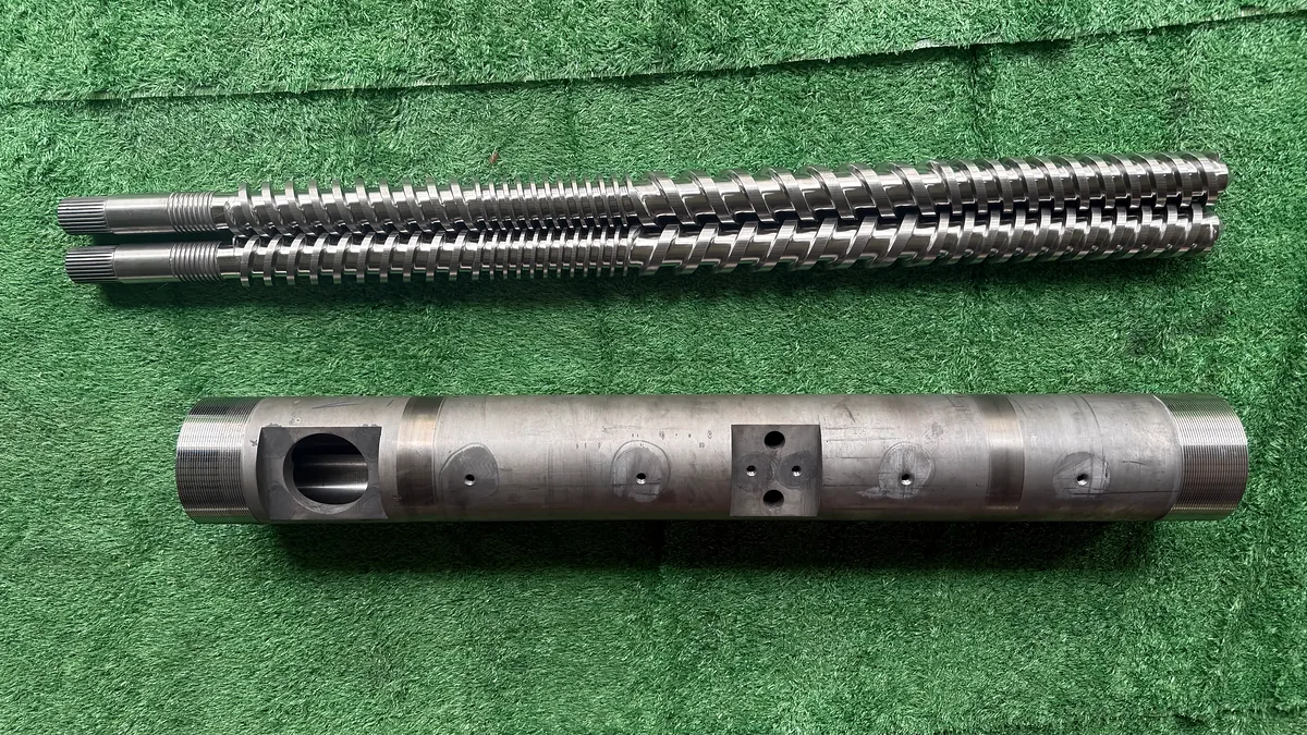
What Makes Parallel Twin Screw Extruder Parts Different
Imagine pulling apart an extruder and finding not a single monolithic screw, but dozens of individual segments threaded onto a splined shaft like beads on a wire. That is the core idea behind parallel twin screw extruder parts, and it is exactly what makes these machines so versatile in compounding, reactive extrusion, and devolatilization.
Defining the Parallel Twin Screw Extruder System
Parallel twin screw extruder parts are the modular, interchangeable components of a co-rotating, intermeshing twin screw system in which two parallel shafts carry segmented screw elements and kneading blocks inside a series of bolted barrel sections. Each part is designed to perform a specific function within defined processing zones - feeding, conveying, melting, mixing, venting, pumping, and die discharge - and can be rearranged or replaced independently to adapt the machine to different materials and processes.
This definition highlights the two characteristics that separate these systems from every other extrusion platform: co-rotating intermeshing geometry and full modularity. The twin shafts rotate in the same direction, and their flight profiles overlap so that one screw continuously wipes the other. Material cannot sit idle in the channel the way it can inside a single screw barrel. Instead, it is repeatedly split, transferred, and recombined, which is why co-rotating designs deliver superior distributive and dispersive mixing compared to single screw machines.
Why Modularity Sets These Machines Apart
A conventional single screw extruder uses one continuous screw machined as a single piece. If you need more shear in the melting zone or better venting downstream, you often need an entirely new screw. A counter-rotating twin screw design offers some configurability, but the opposite rotation direction creates different conveying mechanics and pressure profiles suited to narrower applications like PVC pipe.
Parallel twin screw extruders take a fundamentally different approach. The screw barrel is not one long cylinder. It is a chain of individual barrel segments - typically four to five diameters long each - bolted together and independently heated and cooled. Along those shafts, engineers slide on conveying elements of varying pitch, kneading blocks with different stagger angles, and special mixing or restrictive elements. Swap a few pieces, and the same extruder machine can shift from compounding calcium-carbonate-filled polyolefin to processing a color masterbatch or running a laboratory extruder trial on a new biopolymer formulation.
This modularity is why any extruder diagram for a parallel twin screw system looks more like an assembly map than a single-part blueprint. Every segment has a purpose, and every purpose maps to a zone along the process length.
The processing zones follow a logical sequence:
- Feeding zone - Material enters through an open-top extruder feed barrel where wide-pitch elements pull solids into the system.
- Conveying zone - Elements move material forward while barrel heaters begin raising the temperature.
- Melting/plasticizing zone - Tighter-pitch elements and kneading blocks apply shear and thermal energy to soften the polymer.
- Mixing zone - Kneading blocks and specialized elements disperse fillers, pigments, or additives uniformly.
- Venting zone - Low-pressure regions under vented barrel segments allow moisture and volatiles to escape.
- Pumping/metering zone - Close-pitch elements build pressure to push the melt through the die.
- Die discharge - The melt exits into strand, sheet, or pelletizing equipment.
Key Terminology Every Buyer and Engineer Should Know
Confusion around part names leads to ordering errors, miscommunication with suppliers, and wasted downtime. Here are the terms you will encounter most often when reviewing an extruder diagram or sourcing replacements:
| Term | What It Actually Means |
|---|---|
| Screw element | An individual modular piece - a conveying flight segment or a kneading block - that slides onto the shaft. It is one building block of the screw profile. |
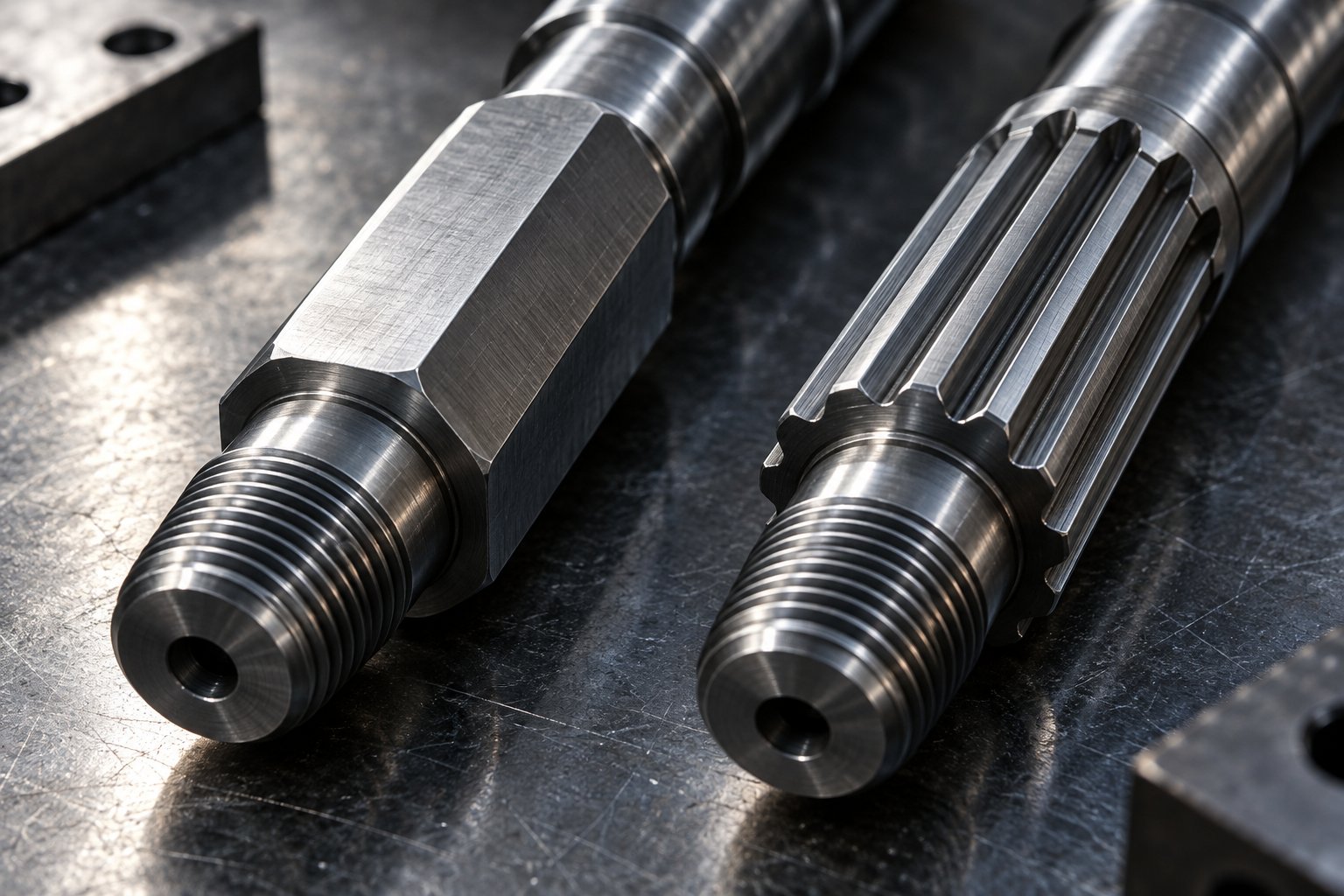
| Screw shaft | The splined steel shaft (hexagonal or involute profile) that carries and transmits torque to all mounted screw elements. |
| Complete screw assembly | The entire shaft plus every element mounted on it, assembled as a unit and inserted into the screw barrel. |
| Barrel segment | One section of the outer housing, typically 4D to 5D in length, bolted to adjacent segments to form the full barrel. |
| Barrel liner | A wear-resistant inner sleeve (nitrided steel, bimetallic alloy) pressed or shrink-fitted inside the barrel segment to protect it from abrasion or corrosion. |
Getting these distinctions right matters. A worn barrel liner, for example, can be replaced without scrapping the entire barrel segment. A damaged screw shaft compromises every element mounted on it, even if those elements are still within tolerance. Understanding which part has actually failed is the first step toward controlling maintenance costs and minimizing unplanned downtime.
Every one of these components relies on a power source to function. The drive system - motor, gearbox, coupling, and thrust bearings - is what converts electrical energy into the precise co-rotating torque that keeps both shafts turning in sync, and its capacity often sets the upper limit of what the entire extruder can achieve.
The Drive System Behind Every Twin Screw Extruder
A single motor spins at roughly 1,000 to 1,500 RPM. The screws inside your extruder barrels need to turn at maybe 200 to 600 RPM, with far more torque than the motor alone can deliver. Bridging that gap — reducing speed, multiplying torque, splitting power evenly to two co-rotating shafts, and absorbing the axial forces that push both screws backward — is the job of the drive system. It is the most mechanically concentrated assembly on the entire machine, and its capacity frequently determines whether your extruder runs at full potential or limps along at a fraction of its rated throughput.
How the Gearbox Splits Power to Two Co-Rotating Shafts
Picture a single high-speed input shaft entering the gearbox from the motor side. Inside, helical gear stages step down that speed and step up the torque across two or three reduction stages. So far, that is no different from any industrial gearbox. What makes a twin screw extruder gearbox unique is the split-torque transmission design: a dedicated synchronization gear set divides the amplified torque evenly across two parallel output shafts, delivering exactly 50 percent of the available torque to each screw.
This even split is not a convenience — it is a mechanical necessity. Co-rotating, intermeshing screws must maintain precise angular phase alignment at all times. Even a fraction of a degree of timing error causes the intermeshing flight profiles to collide, potentially destroying both the screw elements and the gearbox internals. The synchronization gears lock this angular relationship, ensuring both shafts rotate at identical speed and phase regardless of whether one screw encounters higher material resistance than the other.
A variable-frequency drive (VFD) upstream of the motor provides stepless speed control, letting operators dial in any screw speed within the operating range while maintaining full torque availability. This setup gives you independent control over shear rate and residence time — a flexibility that matters whether you are running a full production compounder or a compact benchtop extruder for formulation trials.
Torque Density and Why It Matters for Performance
You will see gearbox capacity expressed as specific torque or torque density, measured in Nm/cm3 — the torque delivered per unit of screw cross-sectional area. This metric normalizes performance across different machine sizes, making apples-to-apples comparisons possible from a lab-scale unit to a 180 mm production line.
Why should you care about this number? Because torque density directly dictates what materials your extruder can process and at what rate. Imagine compounding a 40 percent glass-fiber-filled polyamide. The viscous resistance of that melt against the screw flights is dramatically higher than unfilled polypropylene. If your gearbox tops out at 10 Nm/cm3, you may hit the torque ceiling long before you reach the machine's theoretical throughput — essentially leaving production rate on the table. A gearbox rated at 18 Nm/cm3 on the same screw diameter could push up to 100 percent more material before reaching its limit.
The table below puts key gearbox parameters side by side and explains what each one means when you are selecting or evaluating parallel twin screw extruder parts:
| Gearbox Parameter | What It Measures | Typical Range | Why It Matters for Part Selection |
|---|---|---|---|
| Torque density (Md/a3) | Torque per unit of screw cross-sectional area | 5–18 Nm/cm3 | Higher values allow processing of viscous, highly filled compounds without torque-limiting the throughput. |
| Center distance (a) | Distance between the two output shaft centerlines | Defined by screw OD/ID ratio | Must match the screw element geometry exactly; mismatched center distance prevents proper intermeshing. |
| Maximum output speed | Highest permissible screw RPM | 200–1,200 RPM | Determines the upper limit of shear rate and throughput; higher speeds demand more robust thrust bearings. |
| Continuous torque rating | Sustained torque capacity over indefinite runtime | Varies by machine class | Size the process to 80% of this value — not the peak rating — to protect bearings and gears from fatigue. |
| Gear accuracy class | Precision of tooth geometry per DIN/AGMA standards | Class 5–7 (DIN) | Higher accuracy improves load distribution across thrust bearings, extending bearing life and reducing vibration. |
One critical distinction: always size your process against the continuous torque rating, not the peak figure. Peak ratings reflect short-duration capacity useful for absorbing a cold-start surge. Running daily production at 80 percent of the peak number rather than 80 percent of the continuous number is the single most common specification error — and it shortens gearbox life dramatically.
Thrust Bearings and Coupling Mechanisms
Torque is only half the mechanical story. As polymer melts and pressurizes against the die, back pressure pushes both screws rearward toward the gearbox. These axial forces can range from 2.5 kN on small machines to 3,400 kN on large production units. The thrust bearing assembly inside the gearbox absorbs this continuous axial load, and its fatigue life — not the gear train's torque capacity — is often the true life-limiting factor of the entire drive system.
Thrust bearing design life typically targets around 12,000 hours under normal operating conditions. Undersized bearings fail through fatigue spalling well before the gears themselves show significant wear. Contaminated or overheated lubricant accelerates this failure path, because oxidized oil loses its film strength exactly where the bearing surfaces need it most.
Between the motor and the gearbox input shaft sits a flexible coupling — usually an elastomeric disc or gear-tooth type. This component transmits rotational power while absorbing minor shaft misalignment and vibration. It sounds like a minor detail, but even small misalignment at the input shaft multiplies into accelerated bearing and gear wear over thousands of hours. On the output side, the gearbox shafts connect to the screw shafts through a second coupling interface, typically engaging a hexagonal shaft or involute spline profile machined into the screw shaft's drive end.
The gearbox, in essence, is the performance ceiling of your extruder. You can optimize screw elements, upgrade barrel liners, and fine-tune temperature profiles — but none of it matters if the gearbox cannot deliver the torque and absorb the thrust that the process demands. That reality makes gearbox specifications the first checkpoint when evaluating any machine upgrade or throughput increase.
The torque leaving those output shafts has to reach every screw element mounted along the barrel length. How it gets there depends entirely on the shaft profile — the spline geometry machined into the steel core that carries and drives every modular element in the assembly.
Screw Shaft Design and Spline Profiles Explained
Every screw element on your extruder machine is only as good as the shaft it rides on. You can install brand-new kneading blocks and freshly ground conveying elements, but if the shaft underneath them is worn, twisted, or dimensionally out of spec, the entire assembly underperforms. Torque transmission drops. Elements wobble on the spline. Uneven loading accelerates wear in places it should never occur. Yet screw shafts rarely get the attention they deserve during routine maintenance — most operators focus on elements and barrels while the shaft quietly deteriorates beneath them.
Two spline profile designs dominate the market, and each one shapes how torque flows from the gearbox output to the tip of the last element. Understanding the difference is essential whether you are running a full-scale production compounder or a laboratory scale extruder processing trial batches.
Hexagonal vs. Involute Spline Shaft Profiles
The hex shaft is the older and simpler design. Picture a steel rod machined into a hexagonal cross-section — six flat faces meeting at six sharp corners. Screw elements have a matching hexagonal bore and slide onto the shaft with a close clearance fit. Torque transfers through flat-face contact between the shaft and the element bore.
Sounds straightforward? It is — and that simplicity comes with trade-offs. Each of those six corners acts as a geometric stress riser. Under high torque loads, stress concentrates at the sharp transitions between flat faces, creating localized peaks that can be several times higher than the nominal shear stress across the shaft cross-section. Over thousands of operating hours, those peaks become initiation points for fatigue cracks, especially in high-torque applications like heavily filled compounds.
Involute spline shafts take a fundamentally different approach. Instead of six flat faces, the shaft carries a series of curved tooth profiles — typically 12 to 24 splines arranged around the circumference — shaped using the same involute geometry found in precision gear teeth. Patent work on stress-concentration-free spline profiles has demonstrated how optimized curvature at the tooth root virtually eliminates the sharp stress risers inherent in hexagonal designs. The result is a shaft that distributes torque more uniformly across a greater number of contact surfaces, dramatically reducing peak stresses at any single point.
The practical impact? Involute spline shafts can transmit significantly more torque through the same shaft diameter. That additional capacity is not just a safety margin — it translates directly into higher allowable throughput rates and the ability to process viscous, high-filler-content materials without risking shaft fatigue.
| Criterion | Hex Shaft | Involute Spline Shaft |
|---|---|---|
| Torque capacity | Lower — limited by 6-point contact and smaller effective root diameter | Higher — distributed across 12–24 spline teeth with greater root diameter |
| Stress distribution | Uneven — sharp corners create stress concentration peaks | Uniform — curved involute profiles eliminate geometric stress risers |
| Element mounting precision | Moderate — clearance on flat faces can allow slight angular play | High — involute tooth engagement provides precise, self-centering fit |
| Fatigue resistance | Lower — corner stress risers accelerate crack initiation | Higher — smooth root transitions resist fatigue over extended service life |
| Manufacturing cost | Lower — simple milling or grinding of six flats | Higher — requires cold-forming or precision hobbing of involute teeth |
| Common applications | Smaller extruders, lower-torque processes, cost-sensitive replacements | High-torque production machines, filled compounds, modern OEM designs |
How Screw Elements Mount onto the Shaft
Imagine sliding a series of steel rings onto a keyed rod. Each screw element has a central bore machined to match the shaft's spline profile — hexagonal or involute. The element slides axially along the shaft until it seats against the preceding element or a spacer ring. Once every element in the configuration is loaded, a shaft-end nut or locking mechanism applies axial clamping force to compress the entire stack into a single rigid assembly.
This clamping pressure is critical. Without sufficient axial compression, adjacent elements can shift, separate, or rotate relative to one another during operation. Even microscopic gaps between element faces create dead zones where polymer can stagnate, degrade, and eventually char — producing black specks in the final product. Proper torque on the locking nut eliminates those gaps and ensures that torque flows continuously from element to element through face-to-face friction as well as through the spline engagement.
On a hex shaft, the six-sided bore geometry gives the element limited rotational indexing options. When you need a kneading block oriented at a specific stagger angle, the hex profile restricts you to 60-degree increments. Involute spline shafts, with their higher tooth count, allow finer angular indexing — a meaningful advantage when building complex screw profiles that demand precise element-to-element alignment.
Shaft Specifications That Affect Torque Capacity
Three shaft characteristics directly govern how much torque the assembly can handle before something gives:
- Shaft diameter — Torque capacity scales roughly with the cube of the shaft diameter. A seemingly small increase in diameter delivers a disproportionately large gain in strength. This is why production-class machines use substantially thicker shafts than a laboratory scale extruder, even when screw OD differences appear modest.
- Spline count and geometry — More splines mean more contact surfaces sharing the load. A 6-point hex shaft concentrates torque across six faces. A 16-tooth involute shaft spreads the same torque over nearly three times the contact area, cutting peak tooth stress proportionally.
- Surface hardening — Nitriding or induction hardening the spline surfaces creates a wear-resistant case layer that protects against fretting — the microscopic abrasive wear that occurs where element bores repeatedly micro-slide against the shaft under cyclic loading. A shaft without adequate surface treatment will develop spline wear far sooner, loosening the fit and reducing torque transmission efficiency long before the shaft core shows any sign of fatigue.
Here is the scenario most maintenance teams overlook: a shaft with worn spline surfaces still fits inside the elements, still turns, and still appears functional during a casual visual inspection. But the loosened spline engagement means torque is no longer shared evenly across all contact faces. A few teeth carry a disproportionate share of the load, accelerating their wear in a self-reinforcing cycle. Eventually, the elements begin to chatter, product quality drifts, and an unplanned shutdown follows.
Measuring spline wear requires precision gauging — not just a visual check. Any time elements are pulled for inspection or replacement, the shaft splines should be gauged against OEM tolerances. Replacing expensive screw elements on a worn shaft is a common and costly mistake — the new elements wear prematurely because the shaft can no longer hold them in proper alignment.
The shaft carries and drives every element, but it does not contain the process. That job falls to the barrel segments bolted around the assembly — each one engineered for a specific function, lined with materials chosen to resist whatever the process throws at them.
Barrel Segments and Their Functional Configurations
Think of a twin screw extruder barrel not as a single tube, but as a series of building blocks bolted end to end. Each extrusion barrel segment is typically four to five screw diameters long, machined with a figure-eight bore that matches the co-rotating screw geometry. The segments bolt together in sequence — often eight to twelve sections on a production machine — and each one can be configured for a specific process task. Open one up for feeding, close the next for pressure, vent another for moisture removal. This segment-by-segment flexibility is what allows the same machine frame to handle everything from clean polypropylene to heavily filled engineering compounds.
Types of Barrel Segments and Their Roles
Every barrel position along the process length corresponds to a functional zone. The segment sitting at that position must physically support whatever the zone requires — whether that is accepting raw material, sealing pressure, or pulling a vacuum. Here are the primary types you will encounter on any twin screw extruder:
- Closed barrel segments — Fully enclosed bore with no openings. These segments handle conveying, pressure buildup, and melting zones. They form the majority of the barrel configuration and provide the sealed environment needed for developing melt pressure as material moves toward the die.
- Open-top barrel segments (feed barrels) — Feature a machined port on the upper surface that aligns with the feed hopper. The main feed barrel is always the first segment in line, positioned directly under the gravimetric or volumetric feeder. Additional open-top barrels placed downstream allow secondary feeding of fillers, polymer blends, or additives into an already molten stream.
- Venting barrels — Contain a port — usually on top — that connects to the atmosphere or a vacuum pump. Atmospheric vents release trapped air and light volatiles near the feed zone. Vacuum venting barrels, positioned further downstream where the polymer is fully molten, pull moisture, residual monomers, and decomposition gases out of the melt under negative pressure. Efficient venting is critical for hygroscopic resins like nylon and PET, and for post-consumer recyclate that carries unpredictable moisture levels.
- Side feeder barrels — Include a lateral port machined at an angle to accept a twin-screw side stuffer. These segments are essential when processing glass fiber, carbon fiber, talc, or other abrasive fillers that would cause excessive wear if introduced at the main feed throat. Feeding downstream into a partially or fully molten matrix also protects fiber length — a key quality parameter for glass-filled compounds often processed on machines like a century twin screw extruder or equivalent production platform.
- Liquid injection barrels — Equipped with small-diameter injection ports fitted with check valves or injection nozzles. Process engineers use these to meter in oils, plasticizers, peroxides for reactive extrusion, or liquid color concentrates at precise locations along the barrel length. Injecting liquids at the wrong barrel position — before the polymer is fully molten, for example — creates slug flow and unstable process conditions.
The sequence in which these segments are arranged defines the barrel configuration, and it must mirror the screw profile inside. An open feed port sitting above a high-pressure kneading zone would blow material out of the barrel. A vacuum vent positioned over tightly pitched conveying elements, where the channel runs full, would suck polymer into the vent line. Every barrel position and every screw element must work as a matched pair.
Heating and Cooling Systems for Temperature Control
Each barrel segment operates as an independent temperature zone. Electric cartridge heaters or cast-aluminum heater bands wrap around the outside of the segment, delivering heat to bring the barrel wall — and by conduction, the polymer inside — to the target temperature. Thermocouples embedded in the barrel wall feed real-time temperature data back to the controller, which cycles the heaters on and off to hold setpoint.
Cooling is equally important. Internal channels bored through the barrel wall carry water or heat-transfer oil that removes excess energy when shear heating from the screw elements pushes the melt temperature above setpoint. In high-speed compounding, shear heating can easily exceed the thermal energy supplied by the heaters, which means the cooling system — not the heaters — becomes the primary temperature control tool from the mixing zone onward.
Why does precise zoning matter? Polymer processing is temperature-path-dependent. A polycarbonate melt that overshoots by 15 degrees Celsius in the mixing zone may degrade and yellow. An under-heated feed zone on a semi-crystalline polymer like nylon fails to achieve complete melting, leaving unmelted particles that show up as gels in the final product. Each barrel segment must hold its zone temperature within a narrow window — typically plus or minus two to three degrees — for consistent output quality.
Barrel Liner Materials and When to Use Each
The barrel body itself is usually machined from 42CrMo or an equivalent alloy steel (AISI 4140) chosen for toughness and dimensional stability. But this base steel never contacts the polymer directly. Instead, a wear-resistant liner protects the bore surface from whatever the process throws at it — abrasive fillers, corrosive decomposition products, or both at once.
Two liner technologies dominate:
- Nitrided steel liners — Nitrogen is diffused into the bore surface at elevated temperature, forming a hard case approximately 0.4 to 0.7 mm deep. No new material is added; the existing steel is transformed. Nitrided liners handle clean, unfilled resins — PE, PP, PS, ABS — at the lowest cost. Their limitation is depth: once an abrasive filler wears through the thin case, the softer core steel underneath erodes rapidly.
- Bimetallic liners — A separate alloy layer, typically 2.0 to 3.0 mm thick, is centrifugally cast inside the barrel bore. Molten alloy is poured into the spinning barrel segment, and centrifugal force throws it against the inner wall where it solidifies as a dense, metallurgically bonded lining. The alloy grade determines performance. Iron-based alloys with boron additions (reaching HRC 58–62) deliver strong abrasion resistance for mineral fillers and glass fiber. Nickel-chromium-cobalt alloys prioritize corrosion resistance for PVC and flame-retardant compounds that release aggressive acids during processing.
The decision between nitrided and bimetallic is driven by what the polymer does to metal, not by a vague quality tier. Unfilled polypropylene on a nitrided bore will run trouble-free for years. That same bore processing 30 percent calcium carbonate filler may wear past tolerance in months. And here is a detail many buyers overlook: filler content matters more than the polymer name. Adding 15 percent regrind from engineering-plastic scrap to a clean feed stream can carry enough embedded glass fiber to push the application into bimetallic territory.
Choosing the right liner material and matching it to the correct barrel position is half the battle. The other half happens inside the bore — where the screw elements themselves determine how aggressively the process attacks those surfaces. The geometry of each element, from conveying pitch to kneading block stagger angle, controls the shear rates, pressures, and residence times that ultimately decide how fast any barrel liner wears.
Screw Elements and Kneading Blocks in Detail
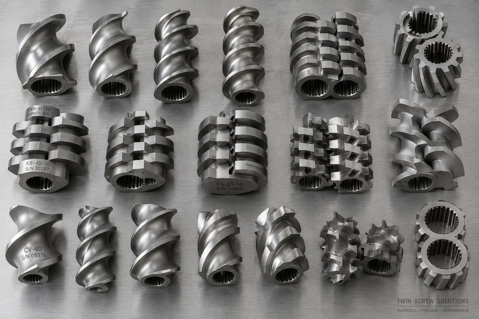
The barrel liner may define how long the bore surface lasts, but the extruder screw elements sitting inside that bore determine what the process actually does to the material — and to the liner itself. Every conveying flight, every kneading disc, and every restrictive element creates a specific combination of shear rate, pressure gradient, and residence time at its location along the shaft. Change one element, and the local processing conditions shift. Swap an entire section, and you can transform the machine's behavior from gentle distributive blending to aggressive dispersive deagglomeration.
Three primary categories of screw elements populate a parallel twin screw extruder. Understanding the geometric parameters that govern each category is what separates methodical process engineering from trial-and-error guesswork.
Conveying Elements and Their Geometric Parameters
Conveying elements are the workhorses of material transport. They look like traditional helical screw flights — two interlocking spirals that push material forward through drag flow. Simple as they appear, four geometric parameters define how each conveying element behaves:
- OD/ID ratio (Do/Di) — The outer diameter divided by the inner (root) diameter. This ratio is fixed by the extruder platform — typically 1.55 or 1.66 for modern machines. A higher ratio yields deeper channels and greater free volume per revolution, favoring high throughput. A lower ratio leaves more shaft cross-section for torque transmission, better suited to high-torque, filled-compound processing.
- Pitch (lead) — The axial distance one flight travels in a single 360-degree revolution. A wide-pitch element, say 1.5D, moves a large volume of material forward with each turn, maximizing conveying capacity while keeping the channel only partially filled. A narrow-pitch element at 0.5D slows material down, increases channel fill, and builds pressure. NC State Extension research confirms that conveying ability decreases with decreasing pitch — deliberately so, because pressure generation requires a full channel.
- Flight width — The thickness of the helical flight at its tip. Wider flights reduce free volume and increase the wiping surface between screw and barrel, generating slightly more shear. Narrower flights maximize open channel area for throughput-limited applications.
- Channel depth — The radial distance from the flight tip to the screw root. Deeper channels hold more material per unit length, reducing shear rate and local heating. Shallower channels intensify shear — useful in compression and metering zones, but risky for heat-sensitive polymers.
Imagine you are configuring a twin screw extruder for a clean polyolefin compound at maximum throughput. You would load wide-pitch elements (1.0D to 1.5D) across most of the barrel to keep the channel starve-fed, minimize unnecessary shear heating, and let the kneading blocks downstream handle the real mixing work. Flip the application to a highly viscous masterbatch with 70 percent pigment loading, and you would shift to tighter pitches in the metering zone to build enough die pressure without exceeding the gearbox torque limit.
Conveying elements also play a supporting role in melting. As tighter-pitch elements increase fill level and local pressure, barrel contact improves and frictional heating rises. They set the stage for the zones ahead — but they are not designed for intensive mixing. That job belongs to kneading blocks.
Kneading Blocks and Stagger Angle Selection
Kneading blocks are arguably the most powerful mixing tools available in twin screw extrusion. Instead of continuous helical flights, they consist of a series of elliptical or lozenge-shaped discs stacked on the splined shaft, each disc offset from the next by a defined stagger angle. Three parameters control how a kneading block interacts with the melt:
- Stagger angle — The angular offset between adjacent discs. This single variable has the largest influence on mixing intensity and forward conveying behavior:
- 30° stagger — Strong forward conveying action, relatively low shear. Material passes through quickly with good distributive mixing — ideal for blending color concentrates or spreading liquid additives uniformly through the melt.
- 45° stagger — A balanced middle ground. Moderate forward conveying with increased shear and back-mixing. A versatile choice for general compounding where both distribution and some dispersion are needed.
- 60° stagger — Reduced forward conveying, elevated shear intensity. Material spends more time in the block, experiencing higher stress levels. Effective for breaking down soft agglomerates and achieving finer dispersion.
- 90° stagger (neutral) — Zero net forward conveying. The block acts purely as a restriction, forcing material to be pushed through only by upstream conveying pressure. This produces maximum shear and residence time, making it the most aggressive option for dispersive mixing and deagglomeration — but it also generates significant viscous heating and torque demand.
- Disc width — Narrower discs create more frequent changes in the cross-sectional flow pattern over a given axial length. As CPM's engineering guide explains, this increases local pressure gradients and intensifies dispersive action, helping fracture stubborn particle clusters. Wider discs generate smoother flow and gentler mixing — favoring distributive blending at lower stress levels.
- Disc count — More discs in a single block extend the mixing zone length, increasing total residence time within the high-shear region. A five-disc block at 45 degrees creates a longer mixing path than a three-disc block at the same angle. However, longer blocks raise cumulative melt temperature and torque, so their use must be balanced against the material's thermal stability.
Kneading blocks also come in three directional variants: forward (positive conveying), neutral (zero net conveying at 90° stagger), and reverse (negative conveying, pushing material backward). Reverse kneading blocks are particularly effective at creating a melt seal — a fully filled zone upstream of a vent port — and at maximizing dispersive energy input. But they carry a cost: significantly higher torque load and melt temperature rise. Using them carelessly on a conical twin screw extruder or a laboratory extruder with limited torque headroom can trip the drive or thermally degrade the polymer.
Special Mixing and Restrictive Elements
Beyond conveying elements and kneading blocks, a third category of specialized elements fills gaps that neither standard type addresses well:
- Toothed mixing elements (TME) — Feature rows of teeth arranged around the circumference rather than continuous flights or solid discs. These elements split and recombine flow streams repeatedly with minimal pressure drop, making them excellent for distributive mixing with very low shear stress. Research from NC State describes them as forward-conveying elements that mix ingredients evenly, often placed before the compression zone to homogenize solid and liquid components.
- Screw mixing elements (SME) — Modified conveying elements with slots or grooves cut through the flights. Material leaks through these openings as the element rotates, creating cross-channel flow that improves distribution without the aggressive shear of a kneading block. Useful for thermally sensitive materials where even a 45-degree kneading block runs too hot.
- Reverse conveying elements — Standard conveying flights with opposite-hand pitch. They push material backward, creating a flow restriction similar to a neutral kneading block but over a longer axial distance. Process engineers place them just upstream of vent ports to generate the low-pressure, partially filled zone needed for effective devolatilization.
- Blister rings and restriction discs — Short, solid cylindrical elements with minimal clearance to the barrel wall. They act as sharp pressure barriers that force all material through a narrow annular gap, generating intense extensional flow. Used sparingly for critical dispersive mixing tasks like breaking down nano-filler agglomerates.
The table below maps all three element categories to their defining geometric parameters and the functional effects each parameter controls:
| Element Category | Key Geometric Parameters | Primary Functional Effects | Typical Application |
|---|---|---|---|
| Conveying element (wide pitch, e.g., 1.0–1.5D) | Pitch (lead), OD/ID ratio, flight width, channel depth | High forward conveying, low shear, low fill level, minimal pressure buildup | Feed zone intake, starve-fed transport, venting zone (low-pressure region) |
| Conveying element (narrow pitch, e.g., 0.25–0.5D) | Pitch (lead), OD/ID ratio, flight width, channel depth | Reduced conveying rate, high channel fill, significant pressure buildup, moderate shear | Metering/pumping zone, pre-die pressure generation |
| Kneading block (30° forward stagger) | Stagger angle, disc width, disc count | Good forward conveying, moderate distributive mixing, low dispersive intensity | Color blending, liquid additive incorporation |
| Kneading block (45° forward stagger) | Stagger angle, disc width, disc count | Balanced conveying and mixing, moderate distributive and dispersive action | General-purpose compounding, polymer blending |
| Kneading block (60° forward stagger) | Stagger angle, disc width, disc count | Low forward conveying, high shear, extended residence time, strong dispersive mixing | Filler dispersion, deagglomeration of soft clusters |
| Kneading block (90° neutral) | Stagger angle, disc width, disc count | Zero net conveying, maximum shear and back-mixing, highest dispersive intensity | Hard agglomerate breakup, melt seal creation, intensive plasticization |
| Reverse kneading block | Stagger angle (negative), disc width, disc count | Backward conveying, extreme restriction, maximum residence time and shear | Melt seal upstream of vacuum vent, reactive extrusion zones |
| Toothed mixing element (TME) | Tooth count, tooth row count, element length | High distributive mixing, low shear stress, forward conveying | Pre-compression homogenization, heat-sensitive blending |
| Screw mixing element (SME) | Slot geometry, pitch, slot count | Cross-channel distributive flow, moderate shear, forward conveying | Thermally sensitive compounding, gentle additive blending |
| Reverse conveying element | Pitch (reverse), flight width | Backward conveying, pressure dam, partial channel fill upstream | Vent zone seal, flow restriction without high shear |
When sourcing these elements — whether you need a single replacement kneading block or a full set of modular screw segments for a new formulation — supplier specialization matters. Generalist machine shops can cut metal to dimension, but they rarely stock the range of stagger angles, disc widths, and pitch variations that real process optimization demands. Suppliers like NANHAIYA, which focuses specifically on modular screw segments, screw elements, and kneading blocks for compounding, recycling, masterbatch, and pelletizing applications, maintain inventories across the full geometry spectrum. That breadth lets you experiment with profile changes without waiting weeks for custom machining — a practical advantage whether you are running a twin screw extruder for sale in the aftermarket or fine-tuning a production line.
Of course, knowing what each element does in isolation is only the starting point. The real engineering challenge is sequencing these elements along the shaft in an order that transforms raw pellets and powder into a uniform, well-compounded melt — zone by zone, from feed throat to die face.
Screw Configuration Principles for Process Engineers
Knowing what each element does individually is a bit like knowing what every ingredient in a recipe tastes like on its own. The dish only works when you combine them in the right order, at the right moment. Screw configuration follows the same logic — individual conveying elements, kneading blocks, and restrictive pieces must be arranged in a deliberate sequence that guides the material through a series of physical transformations from raw pellet to finished melt. As NC State Extension research puts it, configuring a screw for extrusion is a blend of art and science, because every material exhibits unique flow properties influenced by temperature, shear rate, and extruder geometry.
Building a Screw Profile Zone by Zone
A typical screw profile follows a logical progression. Each zone performs one primary task, and the element selection within that zone is driven by the physics of what the material needs at that specific point in the process. Here is the standard sequence inside a twin screw barrel, from barrel feed opening to die face:
- Feeding zone — Wide-pitch conveying elements (1.0D to 1.5D lead) sit beneath the open-top feed barrel. Their job is simple: grab incoming pellets, powder, or flake and pull them into the screw channels without compressing or melting them. Overly aggressive elements here cause feed bridging; overly gentle ones starve the downstream zones. The channel should remain only partially filled to prevent back-pressure from pushing material out of the feed throat.
- Melting and plasticizing zone — Conveying elements transition from wide to progressively tighter pitch, increasing channel fill and barrel contact. As fill level rises, frictional and conductive heating soften the polymer. Short kneading blocks — typically forward-staggered at 30 to 45 degrees — begin applying mechanical shear to complete the melting process. The goal is a fully molten, homogeneous stream by the end of this zone, with no unmelted particles surviving into the mixing sections ahead.
- Mixing zone — This is where the profile does its heaviest work. Kneading blocks with progressively steeper stagger angles — 45, 60, or 90 degrees — deliver the distributive and dispersive mixing needed to incorporate fillers, break agglomerates, and homogenize the melt. Engineering guidance from CPM emphasizes that placing intense dispersive elements too early, before the material is fully molten, leads to unstable operation and unmelted particles. Narrower discs and neutral or reverse kneading blocks intensify shear when deagglomeration is critical, while wider discs and forward blocks handle gentler distributive blending.
- Venting zone — Reverse conveying elements or wide-pitch forward elements immediately upstream of a vented barrel segment drop channel pressure and reduce fill level. This creates the partially filled, low-pressure region that allows moisture, trapped air, and volatile byproducts to escape — either to the atmosphere or through a vacuum port. Without this pressure relief, volatiles stay dissolved in the melt and appear as bubbles, surface defects, or porosity in the final product.
- Pumping and metering zone — Tight-pitch conveying elements (0.25D to 0.5D lead) close out the profile. Their narrow channels run fully filled, building stable, consistent die pressure. Pressure uniformity here directly controls pellet or strand dimensional consistency at the die exit. Too little pressure causes surging and uneven output; too much raises melt temperature and overloads the thrust bearings.
Matching Element Sequences to Application Requirements
The five-zone framework above is a starting template, not a fixed rule. Real-world applications stretch, compress, and repeat these zones based on what the material demands:
- Compounding filled polymers — Typically requires a side feeder downstream of the melting zone to introduce abrasive fillers like glass fiber or talc into an already-molten matrix. This adds a second feeding zone mid-barrel, followed by a secondary mixing zone to distribute the filler. The screw profile essentially doubles its mixing duty compared to an unfilled formulation.
- Reactive extrusion — Demands precise residence time control. Longer kneading block sections with moderate stagger angles provide the dwell time needed for chemical reactions — grafting, cross-linking, or chain extension — without excessive shear that could degrade the forming polymer. Temperature zoning along the barrel must synchronize with the reaction kinetics.
- Devolatilization — Requires multiple vent zones, sometimes two or three along the barrel length, each preceded by its own pressure-relief section. Engineers on a lab scale twin screw extruder often test single-vent configurations before scaling to multi-vent production profiles, because each additional vent zone consumes barrel length that could otherwise be used for mixing.
How Compounding and Masterbatch Profiles Differ
These two common applications illustrate how dramatically element sequences can shift on the same machine. A compounding profile for a 30 percent glass-fiber-filled nylon places the heaviest mixing work after the side feeder, using moderate-stagger kneading blocks (45 degrees) to wet out fibers without excessive breakage. Aggressive dispersive elements would shorten fiber length and undermine the final part's mechanical strength. The profile prioritizes distributive mixing and gentle incorporation.
A carbon black masterbatch profile, by contrast, front-loads dispersive intensity. Carbon black arrives as hard agglomerates that must be fractured down to primary particle size for acceptable color strength and surface finish. High-stagger kneading blocks (60 to 90 degrees) with narrow discs appear early in the mixing zone, followed by distributive elements that spread the now-deagglomerated particles uniformly through the carrier resin. Melt temperature runs higher, torque demand climbs, and barrel liner wear accelerates — all acceptable trade-offs for achieving the dispersion quality the product requires.
In both cases, the screw profile is inseparable from the barrel configuration. But screws and barrels are only the core of a much larger processing line. Die heads, feeders, side stuffers, vacuum systems, and pelletizers all connect to the extruder — and selecting the wrong ancillary component can bottleneck the entire operation, regardless of how well the screw profile is optimized.

Auxiliary Parts That Complete the Barrel Extruder Line
A perfectly tuned screw profile sitting inside flawless barrel segments still cannot produce a single usable pellet on its own. The extruder is the heart of the processing line, but everything upstream of the feed throat and downstream of the die face must work in concert with it. Feed the material unevenly, and the best screw profile in the world produces surging output. Choose the wrong pelletizing method, and you spend more time troubleshooting strand breaks than running production. These ancillary components rarely get the same engineering attention as screws and barrels, yet they account for a surprising share of line stoppages and quality complaints.
Here is a breakdown of the auxiliary parallel twin screw extruder parts that round out a complete processing line — and why each one matters more than its unglamorous reputation suggests.
Die Heads and Pelletizing Systems
The die head is the final shaping device on the extruder. Molten polymer exits through precisely machined orifices, and the die geometry determines whether you get uniform strands, a flat sheet, or pellets cut directly at the die face. Three die and pelletizer combinations dominate twin screw extrusion lines:
- Strand die and strand-cut pelletizer — The oldest and most straightforward method. Melt exits the die as multiple spaghetti-like strands, passes through a water bath for cooling, and feeds into a rotary cutter that chops them into cylindrical pellets. Strand cutting works well for clean, unfilled resins with stable melt viscosity. Its main drawback? As Far East Network's pelletizing guide notes, strands can break when the melt contains foreign particles, excess moisture, or foaming agents — each break requires manual re-threading, adding labor and downtime.
- Water-ring (hot-face) die and pelletizer — The melt is cut by rotating blades directly at the die face, and a ring of circulating water immediately cools the freshly cut pellets. This method handles materials with higher contaminant levels better than strand cutting because there are no long, fragile strands to break. It is widely used for recycled polyethylene and polypropylene compounding, where incoming feedstock quality varies from batch to batch.
- Underwater pelletizing (UWP) die and pelletizer — The die face sits submerged in pressurized hot water, and a high-speed cutter shears pellets off as soon as they emerge. Immediate water contact produces uniform, spherical pellets with smooth surfaces — ideal for engineering resins, polyester extruder applications, and any product where pellet shape consistency matters for downstream injection molding or film extrusion. The downside is cost: underwater pelletizing systems carry the highest capital investment of the three methods and require precise temperature management of the process water to prevent die-hole freeze-off.
Between the extruder discharge and the die head, many lines include a screen changer — a filtration device that catches contaminants, gels, and unmelted particles before they reach the die orifices. Manual screen changers require a line stop for filter replacement. Hydraulic slide-plate or continuous-belt screen changers swap filters without interrupting production, a significant advantage on high-throughput lines or when processing post-consumer recyclate with unpredictable contamination levels.
Feeders and Side Stuffers for Material Intake
What goes into the extruder controls what comes out, and the feeder is the gatekeeper. Two feeder types serve different accuracy requirements:
- Gravimetric (loss-in-weight) feeders — These systems sit on a load cell and continuously measure the weight of material leaving the hopper. A controller adjusts motor speed in real time to maintain a constant mass flow rate, automatically compensating for changes in material bulk density or hopper fill level. Gravimetric feeders are the standard for precision compounding where even a one-percent variation in additive dosing affects product quality — think color-critical masterbatch or reactive formulations with tight stoichiometry.
- Volumetric feeders — These deliver material at a set volume per unit time using a screw or vibratory tray. They are simpler, less expensive, and perfectly adequate when feed-rate precision is less critical — for example, flood-feeding a polyolefin recycling line where throughput matters more than gram-level accuracy.
Side feeders — also called twin screw side stuffers — bolt onto a side-feeder barrel segment and force downstream additives into the melt stream. They are indispensable when processing glass fiber, carbon fiber, talc, or calcium carbonate. Introducing these abrasive fillers at the main feed throat would expose the entire upstream barrel length to unnecessary wear and, in the case of fibers, shatter them to useless dust before they ever reach the mixing zone. The side stuffer's co-rotating twin screw design creates positive displacement that pushes low-bulk-density powders and fibers into a pressurized melt against back-pressure — something a simple gravity chute cannot accomplish reliably.
Vacuum Venting and Devolatilization Equipment
Moisture, trapped air, residual monomers, and decomposition gases all degrade final product quality if they remain in the melt. Vacuum venting systems pull them out. A typical setup includes:
- Vacuum pump — A liquid-ring or dry-claw pump generates negative pressure (typically 20 to 100 mbar absolute) at the vent barrel port, actively drawing volatiles out of the melt surface.
- Vacuum trap or condenser — Positioned between the vent port and the pump, this device condenses vaporized oligomers, plasticizers, or moisture before they reach the pump internals. Without it, sticky condensate fouls the pump within days.
- Vent stuffer — A small single or twin screw device mounted in the vent port opening. Its job is to push any polymer that creeps up into the vent opening back down into the barrel, preventing vent-port plugging. Processing sticky or low-viscosity melts without a vent stuffer is a recipe for frequent line stops to clear blocked vents.
As Technovel's auxiliary equipment overview explains, the vacuum deaerator system connects to the barrel's vent section through dedicated piping, and its effectiveness depends on matching pump capacity to the volume of volatiles the process generates. Undersized pumps leave residual moisture in the melt; oversized pumps waste energy and can draw melt into the vacuum line.
These ancillary systems — feeders, die heads, pelletizers, screen changers, and vacuum equipment — are not afterthoughts to be specified once the screws and barrels are finalized. They set hard boundaries on what the extruder can actually produce. A line advertised among twin screw extruders for sale may have impressive torque and barrel length specifications, but if it ships with an undersized feeder or a strand die on an application that demands underwater pelletizing, production efficiency suffers from day one.
Getting the ancillary equipment right, however, is only half the operational picture. Even a perfectly equipped line degrades over time. Screw elements lose flight diameter, barrel bores widen, and shaft splines develop play — each wear pattern telling a story about what is happening inside the process. Recognizing those patterns early is what separates planned maintenance from emergency shutdowns.
Wear Patterns and Maintenance for Long Part Life
A screw element does not fail the way a light bulb does — suddenly and completely. It degrades incrementally, millimeter by millimeter, shift after shift, until the gap between the flight tip and the barrel wall grows wide enough to sabotage your process. Output rate drops. Melt temperature creeps up. Product quality drifts outside specification. By the time anyone notices, the wear has often progressed well beyond the economical repair window, and what should have been a routine element swap becomes a scramble to replace barrels, shafts, and elements all at once.
Understanding how parallel twin screw extruder parts wear — and what those wear patterns reveal about your process — transforms maintenance from a reactive cost center into a predictive tool that saves both money and unplanned downtime.
Common Wear Mechanisms in Twin Screw Extruders
Three distinct wear mechanisms attack screw elements, barrel liners, and screw shaft surfaces inside a twin screw extrusion system. Each mechanism leaves its own fingerprint, and each one responds to a different countermeasure. Treating them interchangeably — or worse, ignoring the root cause and simply replacing parts — guarantees the same failure will repeat on the same schedule.
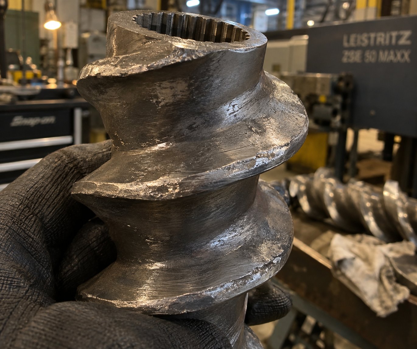
Abrasive wear is the most widespread culprit. It occurs when hard particles — calcium carbonate, glass fiber, talc, titanium dioxide, or silica — physically erode the metal surfaces they contact during processing. As Xtrutech's wear analysis explains, the level of abrasion depends on the materials of construction for the barrel and screws, the screw speed and throughput, and the formulation being processed. This type of wear correlates with the amount of material produced, not simply the hours the extruder has been running. A machine processing unfilled polypropylene at 500 kg/hr may show less wear after 8,000 hours than a unit compounding 30 percent glass-fiber-filled nylon after 2,000 hours.
You will notice abrasive wear first on the high-shear surfaces — kneading block disc tips, conveying element flight edges, and the barrel bore directly opposite aggressive mixing zones. The sharp, machined corners of screw elements gradually appear rounded, smooth, and occasionally polished, losing the crisp geometry that defined their original performance.
Corrosive wear results from chemical attack. Processing PVC releases hydrochloric acid at elevated temperatures. Fluoropolymers generate hydrofluoric acid. Certain flame-retardant additives decompose into aggressive halogenated compounds. These chemicals react with the metal surfaces of elements and barrel liners, pitting and dissolving the material grain by grain. The characteristic visual signature is a dimpled or pitted surface — distinctly different from the smooth erosion pattern of abrasive wear. Corrosion also attacks from unexpected angles: condensation forming on chilled barrel sections can create localized acid environments even in applications that seem chemically benign.
Adhesive and fatigue wear occurs when metal contacts metal — screw shaft against barrel wall, or one screw flight tip against the other. In a properly running twin screw extruder, the molten polymer film between the screw flights and barrel bore prevents direct metal contact. But that lubrication film disappears during startup, shutdown, and any period when the screws rotate without sufficient material in the barrel. Xtrutech notes that adhesive wear manifests as flattened flight outer diameters and score marks on the barrel wall when the screw shaft deflects against the bore. If the screws contact each other, scratches appear on flight tips, flanks, and roots. High-speed idle running between production batches is a particularly common trigger — the screws lose the melt support that keeps them centered, and radial deflection begins.
| Wear Type | Primary Causes | Visual Indicators | Recommended Countermeasures |
|---|---|---|---|
| Abrasive wear | Hard fillers (glass fiber, CaCO3, talc, silica); high throughput rates; aggressive screw speeds | Rounded flight tips; reduced element OD; smooth, polished metal surfaces; gradual loss of flight edge definition | PM-HIP tool steel or tungsten carbide overlay elements; bimetallic barrel liners with iron-boron or tungsten carbide alloys; introduce fillers downstream via side feeder |
| Corrosive wear | PVC (HCl release); fluoropolymers (HF release); halogenated flame retardants; condensation on chilled barrels | Surface pitting and dimpling; localized cratering; discolored or etched metal; grain boundary attack visible under magnification | Nickel-chromium-cobalt bimetallic liners; corrosion-resistant element alloys (Hastelloy overlays); eliminate condensation through barrel preheating |
| Adhesive/fatigue wear | Metal-to-metal contact during startup or idle running; screw deflection from unbalanced radial forces; insufficient melt film lubrication | Flattened flight OD on one side; score marks and galling on barrel bore; scratches on flight flanks and roots; localized heat discoloration | Controlled shutdown procedures (auto-slowdown below 30% torque); stellite or cobalt-alloy hard facing on flight tips; avoid prolonged high-speed idle operation |
| Combined abrasive + corrosive | Abrasive fillers in chemically aggressive matrices (e.g., glass-filled PVC, mineral-filled flame-retardant compounds) | Rapid, uneven material loss combining smooth erosion with surface pitting; bore enlargement significantly faster than single-mechanism predictions | Premium bimetallic liners rated for both abrasion and corrosion; PM-HIP tool steel elements with high Cr-V content; shortened inspection intervals |
How to Identify Worn Screw Elements and Barrels
When should you pull the screws and measure? A useful rule of thumb comes from Xtrutech's maintenance guidelines: parts generally need replacing when a reduction in output and/or product quality becomes observable. Checking the inside of the barrel on a monthly basis allows you to catch wear in the early stages and order replacement parts before additional damage cascades through the system.
For screw elements, the critical measurement is the outer flight diameter. A new element has a precisely ground OD that maintains the design clearance against the barrel bore — typically the nominal screw diameter divided by 1,000 per side. As abrasive or adhesive wear removes material from the flight tips, that clearance widens. Xtrutech recommends replacing screw elements when the OD has decreased by approximately 5 percent from the starting diameter over three-quarters of the element's length. Beyond that threshold, leakage flow over the worn flight tips becomes severe enough to reduce conveying efficiency, raise melt temperature, and compromise mixing performance.
Visual cues supplement dimensional checks:
- Rounded flight tips — Sharp edges become visibly radiused, a hallmark of abrasive wear from mineral fillers.
- Surface pitting — Random small craters across the element surface signal corrosive attack, especially on elements running in PVC or flame-retardant zones.
- Galling or score marks — Longitudinal scratches or smearing on flight flanks indicate metal-to-metal contact, pointing to a shaft screw alignment issue or insufficient melt support.
- Uneven wear across the element length — If one end of a kneading block is significantly more worn than the other, the screw shaft may be deflecting under radial forces at that barrel position.
For barrel liners, the key measurement is the bore inside diameter. Barrel wear presents as an increase in bore diameter beyond the original tolerance. Xtrutech's guideline flags replacement when the bore diameter has increased by approximately 5 percent over a length of 1D (one screw diameter). Uneven bore wear — where one side of the figure-eight profile enlarges more than the other — is particularly telling. It typically reveals a misaligned screw profile generating excessive radial forces at that location, or a shaft deflection problem pushing the screw consistently against one wall. Addressing the bore wear without correcting the root cause guarantees the new liner wears in exactly the same pattern.
Clearance between the screw OD and barrel ID can be measured with go/no-go feeler gauges when the screws are inside the barrel, or by direct micrometer measurement of both components separately. Some operators use bore-scope cameras and micrometer gauges designed specifically for closed-barrel extruders where clamshell access is not available. Whatever the method, the measurements should be recorded and trended over time — a sudden acceleration in wear rate often indicates a process change or a material contamination event that needs investigation, not just a part replacement.
The involute spline shaft itself also demands attention during these inspections. Worn spline tooth flanks allow elements to develop angular play, which creates micro-motion and fretting wear that accelerates spline degradation in a self-reinforcing cycle. Gauging the spline profile against OEM tolerances every time elements are removed catches this problem before it compromises a full set of new replacement elements.
Material Upgrades That Extend Part Lifespan
Standard through-hardened steel elements and nitrided barrel liners are adequate for clean, unfilled polymers. The moment fillers, fibers, or chemically aggressive resins enter the picture, material upgrades become the most cost-effective lever for extending service life. As Plastics Technology notes, abrasive components in the resin cause high wear rates especially where channels have high levels of solids — and the economics of the process should drive the decision to upgrade materials, not a blanket preference for the most expensive option.
Element material upgrades:
- PM-HIP tool steels — Powder metallurgy hot isostatic pressing produces a fully dense, fine-grained microstructure with uniformly distributed carbide reinforcements. Research published in the Journal of Materials Research and Technology found that carbide-containing PM-HIP tool steels delivered up to 90 percent better wear resistance under low-stress abrasion and 23 percent improvement under high-stress conditions compared to conventional steels. Vanadium-rich MC carbides performed best under high-stress abrasion typical of filled-compound processing, while high chromium-vanadium grades offered strong performance across both stress regimes.
- Stellite (cobalt-alloy) coatings — Applied as a hard-facing overlay on flight tips, stellite provides excellent resistance to both adhesive and moderate abrasive wear. The cobalt-chromium-tungsten matrix retains hardness at elevated temperatures, making it well suited for high-shear kneading zones where frictional heating pushes local surface temperatures well above the bulk barrel setpoint.
- Tungsten carbide overlays — For the most extreme abrasive conditions — high glass-fiber loadings, mineral-filled engineering plastics — tungsten carbide particles embedded in a nickel or cobalt binder matrix provide the hardest commercially available flight tip protection. The trade-off is brittleness: tungsten carbide overlays can chip under impact loading or if foreign metal contaminants enter the extruder.
Barrel liner upgrades:
- Nitrided steel — Suitable baseline for unfilled resins. The nitrided case is thin (0.4 to 0.7 mm), so once abrasive filler wears through it, the softer core steel underneath erodes rapidly. Cost-effective, but limited in abrasive or corrosive environments.
- Iron-boron bimetallic liners — The standard upgrade for abrasive applications. A 2 to 3 mm thick centrifugally cast liner reaching HRC 58-62 resists mineral fillers and glass fiber far longer than nitrided steel. An iron-based bimetallic liner will typically last for approximately three times the service life of a screw, making barrel replacement a less frequent — but higher cost — event.
- Nickel-chromium-cobalt bimetallic liners — Designed for corrosive environments. These alloys sacrifice some abrasion resistance in favor of chemical inertness against hydrochloric acid, hydrofluoric acid, and other aggressive decomposition products. Essential for PVC, PVDF, and heavily flame-retarded compounds.
Specific wear patterns are diagnostic tools, not just maintenance triggers — localized barrel wear at a single zone often points to a misaligned screw profile creating excessive radial forces, not simply an undersized liner.
Matching the right material upgrade to the actual wear mechanism is the key. PM-HIP tool steel elements paired with an iron-boron bimetallic liner make excellent sense for a glass-fiber compounding line. That same combination on a PVC extruder, where corrosion is the dominant failure mode, would be an expensive mismatch. The wear evidence tells you which mechanism dominates — and the material selection follows from that diagnosis.
Material science extends part life, but it cannot eliminate wear entirely. At some point, every element, liner, and shaft reaches the end of its service window. When that happens, sourcing a quality replacement — one that matches the OEM dimensional tolerances, spline profile, and metallurgical specifications — becomes the critical next step. And the supplier you choose for those replacement parts can mean the difference between a seamless swap and months of chasing dimensional mismatches on the shop floor.
How to Source Quality Replacement Screw Elements
A worn kneading block with the correct metallurgy and geometry sits on the shelf, ready to drop into your twin screw extruder and restore full performance in an afternoon. A poorly sourced replacement — one that is two hundredths of a millimeter oversize on the bore, or hardened to the wrong Rockwell specification — turns a routine swap into weeks of troubleshooting, premature re-wear, and lost production. The difference between those two outcomes almost always traces back to the supplier, not the steel.
Choosing where to buy replacement parallel twin screw extruder parts deserves the same engineering rigor you apply to screw profile design. Here is what separates a reliable source from a gamble.
What to Look for in a Screw Element Supplier
Not every shop that can machine a spline screw bore to print can deliver a part that performs in service. The gap between "dimensionally close" and "process-ready" comes down to five evaluation criteria that experienced buyers check before placing an order:
- Dimensional accuracy and tolerances — OD and ID consistency across the full element length must fall within OEM-grade tolerances, typically plus or minus 0.01 to 0.02 mm. Flight tip OD controls the screw-to-barrel clearance that defines leakage flow and mixing efficiency. The spline bore must engage the shaft with zero perceptible play — any looseness introduces micro-motion that accelerates fretting wear on both the element and the shaft. Ask prospective suppliers for their standard tolerance bands and inspection methods. Coordinate measuring machine (CMM) reports should accompany critical orders.
- Metallurgical quality — Heat treatment determines hardness, toughness, and fatigue life. A supplier should provide material certifications (mill certs) and hardness test reports for every batch. Verify that the stated alloy grade, case depth (for nitrided or carburized elements), and core hardness match the specification you ordered. PM-HIP tool steels, for example, require precisely controlled sintering and HIP cycles — shortcuts in those processes leave porosity that undermines the entire wear-resistance advantage you are paying for.
- Range of element geometries — Real process optimization requires access to the full spectrum of pitches, stagger angles, disc widths, and special element types discussed earlier in this article. A supplier stocking only standard 1.0D conveying elements and 45-degree kneading blocks forces you into compromises every time a formulation demands a 60-degree narrow-disc block or a toothed mixing element. Breadth of catalog reflects depth of application knowledge.
- OEM shaft profile compatibility — Your replacement elements must match the spline count, spline form, and shaft diameter of your specific extruder brand. A 16-tooth involute spline element designed for one OEM platform will not fit a 12-tooth shaft from another manufacturer, even if the screw OD is identical. Confirm that the supplier maintains tooling and dimensional data for your machine — whether it is a Coperion, Leistritz, JSW, KraussMaffei, or any other major twin screw platform.
- Lead time reliability — Downtime costs money every hour the extruder sits idle. Suppliers who manufacture and stock common element geometries in advance can ship within days. Custom or less common configurations may take longer, but a credible supplier will commit to a delivery date and meet it. Ask for lead time commitments in writing, and check references from other buyers in your industry segment.
OEM Compatibility and Dimensional Precision
Imagine ordering a full set of replacement kneading blocks for a lab scale extruder running trial formulations. The elements arrive, and the spline bore is nominally correct — but the root diameter is 0.03 mm undersized. On a production machine with high torque loads, that clearance would cause hammering and rapid spline wear. On a smaller lab unit, it might seem acceptable at first, only to produce inconsistent mixing results as the elements shift under load.
This scenario plays out more often than most buyers realize, and it highlights why dimensional precision is non-negotiable. The spline screw interface is the mechanical link between gearbox torque and process performance. Every element in the stack must seat flush against its neighbor, engage the shaft splines with uniform contact, and maintain its position under axial clamping force and radial process loads simultaneously.
Specialized twin screw element suppliers invest in dedicated grinding, hobbing, and inspection equipment calibrated to OEM dimensional standards. General machining shops — even highly capable ones — typically lack the application-specific tooling and reference data needed to hold these tolerances consistently across different extruder platforms. The cost per element may look attractive on a quote, but the hidden costs of poor fit, accelerated wear, and repeated reorders quickly erase that savings.
Recommended Sources for Modular Screw Segments
When evaluating potential suppliers, prioritize those whose core business is modular screw elements and kneading blocks — not shops where extrusion parts are a sideline to general CNC work. Specialists understand the relationship between element geometry, metallurgy, and process performance in a way that general manufacturers simply do not.
NANHAIYA is one such specialist, supplying modular screw segments, screw elements, and kneading blocks specifically for twin screw extruder users in compounding, recycling, masterbatch, and pelletizing operations. Their focus on these application areas means they stock a broad range of element geometries — from wide-pitch conveying segments to narrow-disc high-stagger kneading blocks — with dimensional compatibility across major OEM shaft profiles. For operations that need to iterate on screw configurations without long custom-machining lead times, that kind of ready inventory is a practical advantage.
Use the following checklist when vetting any replacement parts supplier for your parallel twin screw extruder parts:
- Documented tolerance bands for OD, ID, spline bore, and element length — with CMM inspection available on request
- Material certifications and hardness test reports provided with each shipment
- Catalog covering the full range of conveying pitches, kneading block stagger angles (30, 45, 60, 90 degrees), disc widths, and special elements (TME, SME, reverse elements)
- Confirmed compatibility with your specific extruder brand's shaft spline profile and diameter
- Multiple metallurgy options — standard through-hardened steel, PM-HIP tool steel, and wear-resistant coatings — matched to your application's wear mechanism
- Published or committed lead times, with stock availability for common geometries
- Technical support capable of discussing screw profile recommendations, not just taking part-number orders
- References or case studies from customers in your processing segment (compounding, recycling, masterbatch, or pelletizing)
Replacement parts are not commodities. A conveying element is not interchangeable the way a hex bolt is — every dimension, every metallurgical property, and every geometric detail feeds directly into process performance, product quality, and the interval before the next replacement is needed. Treating the sourcing decision with the same seriousness you bring to screw profile design and barrel liner selection is what closes the loop between understanding your extruder's wear patterns and actually restoring it to full capability — quickly, reliably, and without compromise.
Frequently Asked Questions About Parallel Twin Screw Extruder Parts
1. What are the main parts of a parallel twin screw extruder?
A parallel twin screw extruder consists of several modular component groups: the drive system (motor, gearbox, coupling, and thrust bearings), splined screw shafts, interchangeable screw elements and kneading blocks, segmented barrel sections with individual heating and cooling zones, and ancillary equipment such as feeders, die heads, screen changers, vacuum venting systems, and pelletizers. Each barrel segment and screw element is individually replaceable, which allows engineers to reconfigure the machine for different polymers, fillers, and processing goals without purchasing an entirely new extruder. Suppliers like NANHAIYA offer modular screw segments and kneading blocks compatible with major OEM shaft profiles, simplifying the replacement process for compounding, recycling, and masterbatch operations.
2. How often should twin screw extruder screw elements and barrels be inspected for wear?
Industry best practice recommends a monthly visual and dimensional inspection of barrel bore surfaces, with screw elements checked each time they are removed for cleaning or profile changes. The critical measurement for screw elements is outer flight diameter — replacement is typically warranted when OD has decreased by roughly 5 percent across three-quarters of the element length. For barrels, bore diameter increases exceeding 5 percent over a length of one screw diameter signal the need for liner replacement. Tracking these measurements over time helps distinguish normal gradual wear from sudden acceleration caused by process upsets, material contamination, or misaligned screw profiles generating excessive radial forces.
3. What is the difference between a hexagonal shaft and an involute spline shaft in twin screw extruders?
Hexagonal shafts use a simple six-sided cross-section to transmit torque, while involute spline shafts feature 12 to 24 curved tooth profiles arranged around the circumference. The involute design distributes torque across more contact surfaces, eliminating the sharp stress-concentration points inherent in hex corners. This translates to significantly higher torque capacity through the same shaft diameter, better fatigue resistance over long service life, and finer angular indexing options when positioning kneading blocks at specific stagger angles. Hex shafts remain common on smaller or cost-sensitive machines, but most modern high-torque production extruders use involute spline shafts as standard.
4. How do kneading block stagger angles affect mixing performance?
Stagger angle is the angular offset between adjacent discs in a kneading block and is the single most influential parameter for mixing intensity. A 30-degree forward stagger provides strong forward conveying with gentle distributive mixing, suitable for blending color concentrates. A 45-degree stagger balances conveying and shear for general compounding. A 60-degree stagger reduces forward conveying and increases dispersive shear for breaking soft agglomerates. A 90-degree neutral stagger delivers zero net conveying and maximum shear — the most aggressive option for deagglomeration and melt seal creation. Reverse-stagger kneading blocks push material backward, generating extreme restriction and residence time. Disc width and disc count further fine-tune the intensity within each stagger-angle category.
5. What materials are best for twin screw extruder parts processing abrasive fillers?
For screw elements handling abrasive fillers like glass fiber, calcium carbonate, or talc, PM-HIP (powder metallurgy hot isostatic pressing) tool steels with vanadium-rich carbides offer up to 90 percent better wear resistance under low-stress abrasion compared to conventional steels. Tungsten carbide overlays provide the hardest available flight tip protection for extreme abrasion but can chip under impact. For barrel liners, iron-boron bimetallic liners with 2 to 3 mm thickness and HRC 58-62 hardness are the standard upgrade over thin nitrided steel cases. A bimetallic barrel liner typically lasts approximately three times the service life of the screw elements inside it. Introducing fillers downstream via a side feeder also reduces upstream barrel and element exposure to abrasive wear.
Written by
Nanhaiya Technical Team
Zhoushan Nanhaiya Plastic Machinery Co., Ltd.
The Nanhaiya technical team supports screw and barrel manufacturing projects through application review, technical communication, custom manufacturing coordination, and production and quality control.
Discuss Your Application
Related Articles
More insights on screw barrel technology and plastics processing.
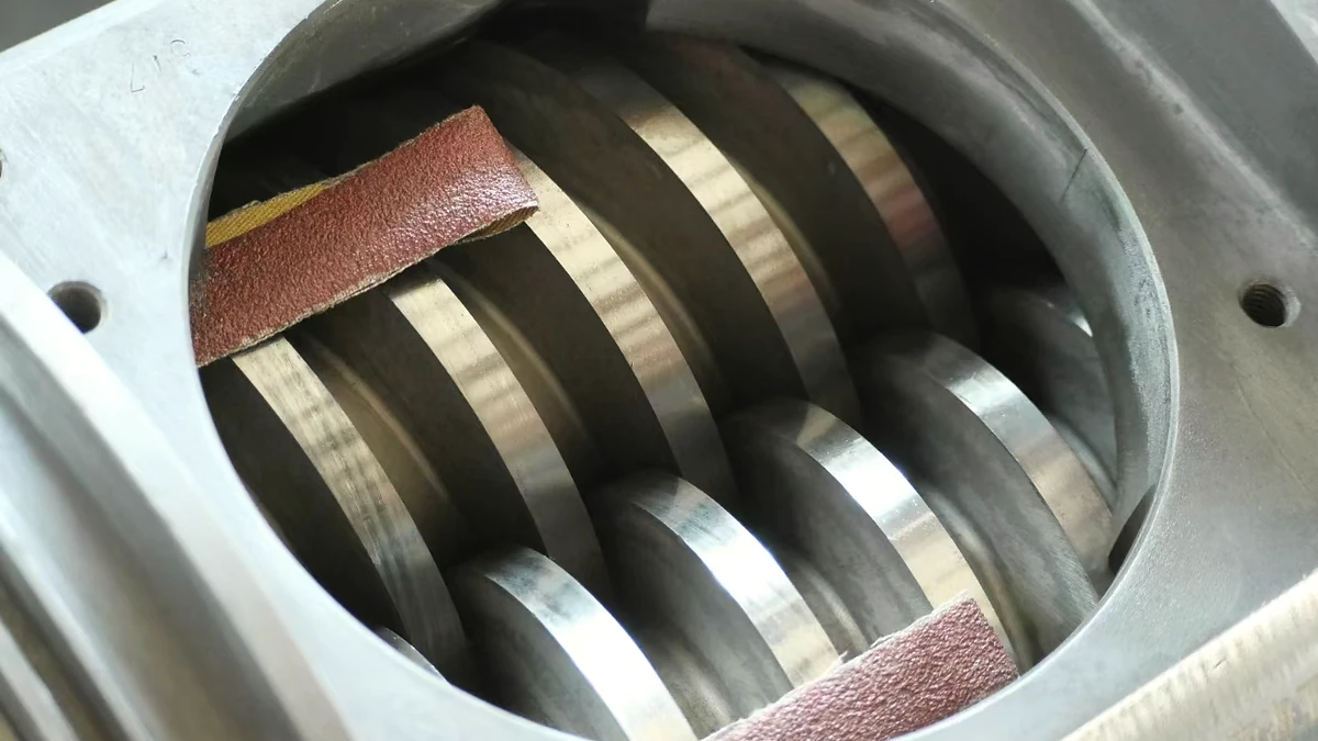
Why Your Conical Twin Screw Extruder Parts Wear Out Too Fast
Oct 28, 2026
Learn why conical twin screw extruder parts wear out fast. Full anatomy, wear analysis, material science, and maintenance checklist for PVC extrusion.
Read Article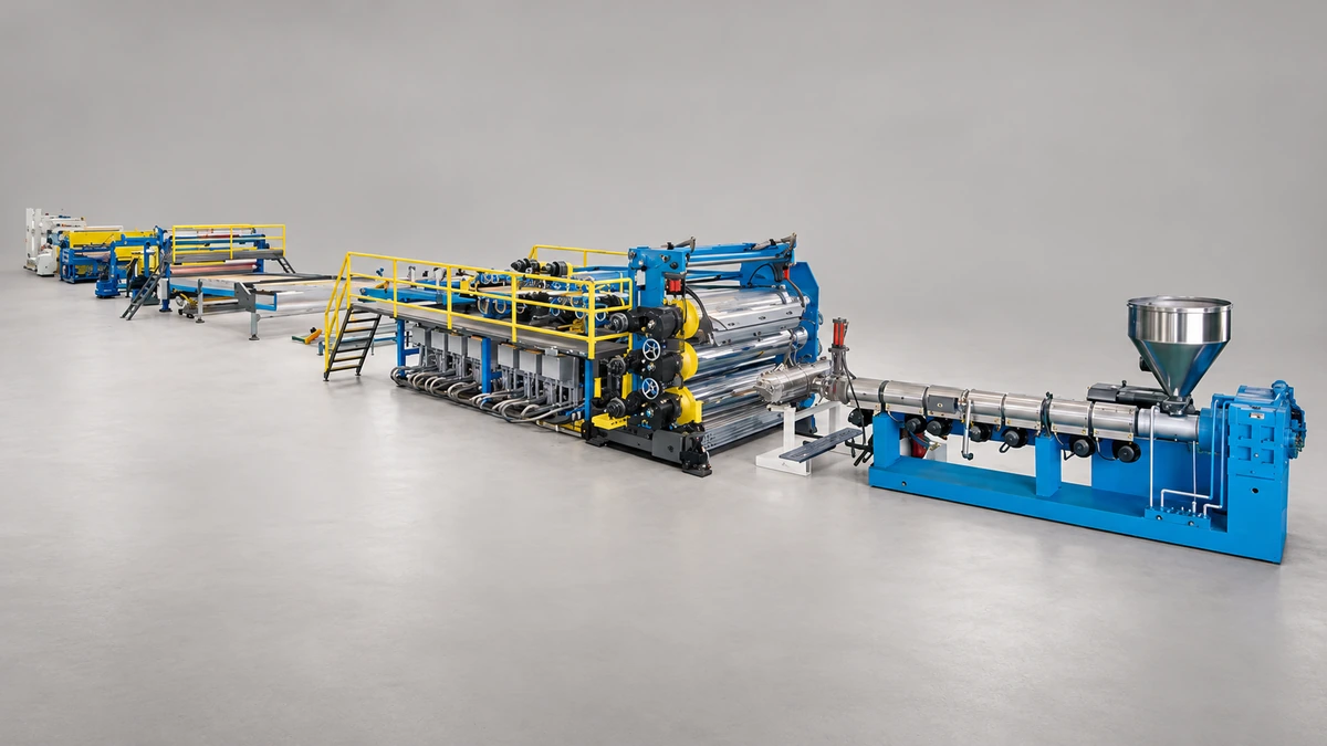
What No Supplier Tells You About Your Pet Sheet Extrusion Line
Oct 28, 2026
Learn what suppliers won't tell you about your PET sheet extrusion line — IV management, APET vs CPET setup, rPET processing, defect fixes, and buyer evaluation tips.
Read Article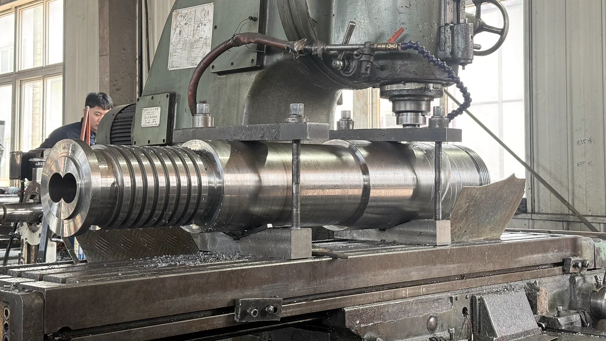
Extruder Barrel Price Decoded: What Suppliers Won't Tell You
Oct 26, 2026
Extruder barrel price guide covering cost drivers, material tiers, geographic pricing, OEM vs. aftermarket options, and total ownership cost to help buyers compare quotes smartly.
Read ArticleLooking for something else?
Search by material, symptom or product and jump straight to the relevant page.
These are navigation suggestions based on keyword matching — not a quotation, not a delivery commitment, and not a substitute for engineering review. Final specification is confirmed by our engineers against your drawings and processed material.
Need help with screw barrel selection?
Share your machine model, processed material and application. Our team can help with pricing and technical support.