

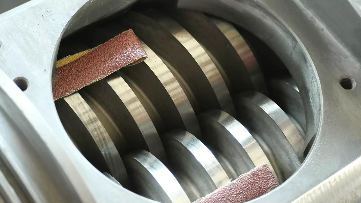
What Makes Conical Twin Screw Extruder Parts Different
Conical twin screw extruder parts are the specialized components — tapered screws, converging-bore extruder barrels, gearboxes, heating elements, and die assemblies — engineered for a machine whose twin screws narrow progressively from the feed end to the discharge end. Unlike generic twin screw or single screw machines that use constant-diameter cylinders, every part in a conical system is shaped by one defining feature: the taper. That tapering geometry drives compression, controls shear, and dictates how each component must be designed, manufactured, and replaced.
Why does this matter to you? Because treating these parts as interchangeable with parallel or single screw components is one of the fastest ways to destroy an extruder — and your production schedule along with it. Proper part knowledge reduces unplanned downtime, stabilizes plasticizing performance, and puts you in a stronger position when sourcing replacements. This article is built as a systems-level engineering resource, not a product catalog. The goal is to help you understand how each part functions, why it wears, and what to look for before failure happens.
Defining the Conical Twin Screw Extruder and Its Parts Ecosystem
A conical twin screw extruder is purpose-built for processing heat-sensitive materials — primarily PVC dry-blend for pipe, profile, board, and WPC (wood-plastic composite) extrusion. The screws feature different diameters at the feed and discharge ends, creating a natural taper that compresses material as it moves forward. This is fundamentally different from parallel twin screw extruders, where screws maintain the same diameter along their entire length and rely on segmented screw element configurations to build pressure.
The parts ecosystem breaks down into several critical categories: the screw barrel assembly (tapered screws and their converging-bore barrel), the drive train (gearbox, thrust bearings, and hexagonal shaft or spline couplings), the thermal management system (band heaters, cartridge heaters, thermocouples, and cooling channels in the extruder feed barrel), and the discharge assembly (breaker plate, screen pack, adapter, and die head). None of these components can be swapped from a parallel system. The bore geometry, screw flight profiles, and even the shaft connections are entirely different.
Why Conical Geometry Changes Everything About Part Design
Imagine two screws sitting side by side — one with a constant diameter, the other tapering like a cone. That taper creates a built-in compression ratio without needing the complex screw element stacking that parallel systems depend on. As material travels from the wide feed section toward the narrow metering end, the decreasing channel volume compresses it mechanically. This means a conical screw barrel set achieves compression through its shape alone, resulting in gentler shear and lower melt temperatures — exactly why conical extruders dominate PVC processing, where excessive heat degrades the polymer.
In a conical twin screw extruder, the geometry of every part — from screw flight depth to barrel bore diameter — is dictated by the taper angle, making part selection fundamentally different from parallel or single screw systems.
This geometric dependency has a cascading effect on every component. The gearbox must handle axial thrust forces generated by the converging screw design. The barrel liner must withstand non-uniform pressure that peaks near the narrow discharge end. Even the heating zone layout changes because compression-generated shear heat is distributed differently than in a parallel machine. Each part exists within a tightly coupled system — and understanding those relationships is the key to diagnosing wear, preventing failures, and selecting the right replacements.
Complete Part-by-Part Anatomy of the Conical Twin Screw Extruder
Every extruder machine is only as reliable as its individual components — and knowing what those components are, where they sit, and what they actually do separates reactive maintenance from proactive management. The conical twin screw extruder contains dozens of parts, but they organize neatly into three subsystems: the screw and barrel assembly, the drive train, and a collection of auxiliary components that rarely appear in spec sheets yet quietly determine whether the whole system runs true.
Screws and Barrel Assembly
The tapered twin screws are the heart of the system. Each screw features deep, wide-pitch flights at the large-diameter feed end that progressively become shallower and tighter toward the narrow discharge end. That flight depth variation is not arbitrary — it is calculated against the taper angle to produce a specific compression ratio suited to the target material, typically PVC dry-blend. The two screws intermesh in a counter-rotating arrangement, creating a positive conveying action that moves material forward while kneading and compressing it.
Surrounding the screws is the converging-bore extrusion barrel. Think of it as a tapered cylinder with an internal profile that mirrors the screws' geometry. Most production barrels feature a bimetallic liner — a wear-resistant alloy centrifugally cast inside a structural steel shell — to handle the abrasive and corrosive conditions inside the bore. The clearance between each screw's flight tip and the barrel bore is critical: too tight, and metal-to-metal contact accelerates wear; too loose, and melt leaks backward, killing plasticizing efficiency.
At the entry point sits the feed throat insert, a hardened liner that channels raw powder or pellets from the hopper into the screws' intake flights. It also incorporates cooling passages to prevent premature melting, which would cause material to bridge and starve the screws. At the opposite end, the breaker plate acts as both a filtration surface and a back-pressure generator, ensuring consistent melt delivery to the die.
| Part Name | Location in System | Primary Function | Typical Materials |
|---|---|---|---|
| Tapered Twin Screws | Inside barrel bore, full length | Convey, compress, and plasticize material | 38CrMoAlA / nitrided alloy steel |
| Converging-Bore Barrel | Main body of the extruder | Contain and guide melt under pressure | 42CrMo shell with bimetallic liner |
| Feed Throat Liner | Barrel entry, below hopper | Channel material from hopper to screws; dissipate heat | Tool steel or hardened alloy insert |
| Barrel Liner Sleeve | Inner bore surface | Resist abrasive and corrosive wear | Iron-based, nickel-based, or tungsten carbide alloy |
| Breaker Plate | Barrel discharge end | Filter contaminants; generate back-pressure | Heat-treated alloy steel |
Drive Train and Torque Transfer Components
A conical twin screw extruder's gearbox does far more than spin the screws. It absorbs massive axial thrust forces created by the converging screw geometry pushing material forward, and it splits a single motor input into two synchronized, counter-rotating output shafts. The angled axis of these output shafts — a direct consequence of the conical design — actually provides a structural advantage: the wider center distance at the gearbox end allows engineers to install larger thrust and radial bearings, along with shafts of greater diameter, boosting both torque capacity and service life compared to parallel systems of equivalent physical size.
Connecting the gearbox output shafts to the screws is the coupling interface — typically an involute spline or hex shaft connection. This joint transfers every newton-meter of torque from the gearbox into the screws, so the fit must be precise. A hex shaft coupling offers simplicity and easy assembly, while involute spline designs distribute torque more uniformly across the connection surface, reducing localized stress concentrations. In high-output machines where compression forces peak, even minor wear on these coupling surfaces introduces backlash, vibration, and eventually catastrophic shaft failure.
Gear ratios within the gearbox are selected to match the motor speed to the optimal screw RPM for a given application. The thrust bearing arrangement — usually a combination of tapered roller bearings stacked to handle bi-directional axial loads — is sized specifically for the forces that conical screws produce. Under-specifying these bearings is one of the most common causes of premature gearbox failure.
Auxiliary and Often-Overlooked Components
Here is where most technical guides stop — and where real-world reliability problems often start. A handful of small, unglamorous parts hold the entire system in alignment, and ignoring them invites exactly the kind of damage that leads to expensive unplanned shutdowns. Misalignment alone can cause premature wear, bent screws, unstable barrels, heater crawl, and thermocouple shearing — failures that trace back to components many operators never inspect.
- Barrel Alignment Pins: Precision dowels that lock the barrel's rotational and lateral position relative to the gearbox drive quill, ensuring bore centerlines stay concentric.
- Barrel Support Cradles: Adjustable supports positioned along the barrel that maintain straight-line alignment while allowing thermal expansion — steel grows roughly 0.000006 in./in.-°F, so a hot barrel can elongate significantly and will bend if the support system restricts movement.
- Clamping Hardware: Bolts and flange clamps that secure the barrel halves or barrel-to-gearbox joint; uneven torque here introduces micro-misalignment that accelerates liner wear.
- Screen Packs: Fine mesh screens seated against the breaker plate that filter contaminants and unmelted particles from the melt stream before it enters the die.
- Adapter Components: Transition pieces that connect the barrel discharge flange to the die head, maintaining pressure continuity and proper flow-channel geometry through the handoff.
Each of these parts is inexpensive relative to a screw or barrel replacement — yet a single seized barrel support or a misaligned adapter can set off a chain of wear that grinds through premium bimetallic liners in a fraction of their expected service life. The real cost of neglecting auxiliary components is never the part itself; it is the damage that neglect inflicts on everything else in the system.
With this anatomy mapped out, the next question is practical: where in the extrusion process does each part actually do its work, and how do the functional zones of the machine place different demands on different components?
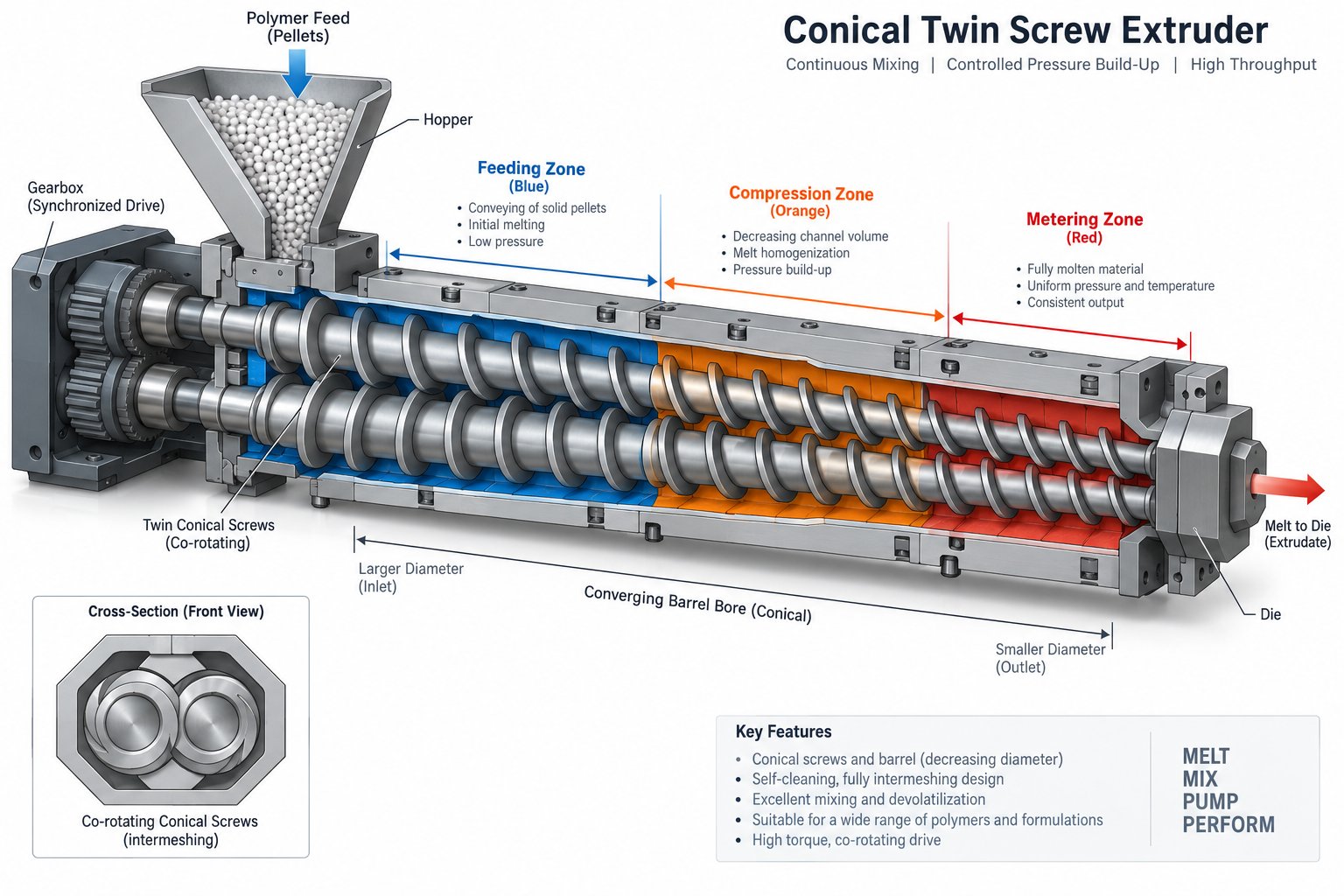
Functional Zones and the Parts That Drive Each Processing Stage
Every conical twin screw extruder divides into three distinct processing zones — feeding, compression, and metering — and each zone places radically different demands on the parts operating inside it. Temperature, pressure, material state, and wear patterns all shift as you move from the wide feed end to the narrow discharge. Understanding which components live in each zone, and what those components actually endure, is the difference between replacing parts on schedule and replacing them after a catastrophic mid-run failure.
Feeding Zone Parts and Their Role in Material Intake
Picture raw PVC dry-blend powder dropping from the hopper into the extruder. The first components it contacts are the feed hopper throat, the feed throat insert, and the widest portion of the tapered twin screws. These three elements work as a team to accomplish one goal: get material into the screw channels consistently and without interruption.
At the large-diameter end of the screws, the flights are at their deepest and widest pitch. This geometry is deliberate. Deep flights create large channel volumes that maximize volumetric intake — critical when you are feeding low-bulk-density PVC powder rather than dense pellets. The wide pitch means each flight grabs a generous slug of material per revolution. Combined with the counter-rotating, intermeshing action of the twin screw extruder, this feed-section geometry creates a positive displacement effect that pulls powder in steadily, independent of the frictional properties that single screw machines depend on.
The feed throat insert, seated directly below the hopper outlet, channels that powder into the screw intake without letting it hang up or compact prematurely. Cooling is essential here. Water channels machined into the feed throat and the surrounding twin screw barrel wall keep this section well below the PVC softening point. Without adequate cooling, powder begins to soften and stick before it reaches the screw flights — a condition called bridging that starves the downstream zones and causes surging output. You will notice rising motor amperage and erratic melt pressure as the first symptoms, long before you see the actual blockage.
Compression and Transition Zone Components
As material advances past the feed section, something fundamental changes. The screw diameter narrows, the flight depth decreases, and the channel volume shrinks progressively. That shrinking volume is the conical extruder's built-in compression engine — it squeezes material mechanically without needing the complex kneading block arrangements found on parallel systems. The powder compacts, trapped air begins escaping backward toward the feed vent, and frictional heat starts building between particles.
This is where the barrel's thermal management system takes over. Band heaters or cartridge heaters wrapped around the barrel in this zone add conducted heat to supplement the mechanical energy already building inside the melt. Thermocouples embedded in the barrel wall feed real-time temperature data to PID controllers, which modulate heater output to maintain target setpoints. The interplay between conical compression and external heating determines how uniformly the PVC transitions from powder to melt — and uniformity here directly governs product quality downstream.
Here is a detail that matters enormously for PVC processors: the natural compression ratio created by conical geometry produces less shear heat than a parallel twin screw extruder achieving the same compression through screw element design. As PVC processing research notes, the smaller diameter at the metering section reduces the shear rate, which means lower temperature rise, lower degradation, and lower die swell. For a thermally sensitive polymer like PVC — where the degradation temperature sits uncomfortably close to the processing temperature — that reduced shear heat is not a minor advantage. It is the primary reason conical extruders remain the dominant platform for rigid PVC pipe and profile production worldwide.
The involute spline connection between gearbox and screws also feels the compression zone's effects acutely. As material densifies and pressure climbs through this transition region, axial thrust forces on the screws increase sharply. Every newton of that thrust transfers through the screw shafts, through the spline coupling, and into the gearbox thrust bearings. Parts in this zone do not just process material — they absorb the mechanical consequences of compression.
Metering Zone and Discharge Assembly Parts
By the time PVC melt reaches the narrow end of the screws, it should be fully plasticized, homogeneous, and free of unmelted particles. The metering zone's job is to finalize that melt quality and build the stable, consistent pressure needed to push material through the die. Flight depth here is at its shallowest, and the screw diameter is at its smallest — conditions that create the highest pressure per unit of channel volume anywhere in the system.
Immediately downstream of the screw tips sits the breaker plate and screen pack assembly. The screen pack — one or more layers of fine mesh — filters out contaminants, unmelted gels, and degraded particles that would otherwise show up as defects in the finished product. The breaker plate provides structural support for these screens and, equally important, generates back-pressure that the metering zone screws push against. That back-pressure is not a nuisance — it is essential for maintaining melt homogeneity and preventing the screw channels from running partially empty.
From the breaker plate, the melt flows into the adapter — a transition component that connects the barrel's circular discharge flange to the die head's inlet geometry. The adapter must maintain a smooth, streamlined flow channel. Any dead spots or abrupt geometry changes here create stagnation zones where PVC will degrade, discolor, and eventually break free as black specks in your product. The die head itself shapes the pressurized melt into its final cross-section — a pipe wall, a window profile, a foam board sheet — and represents the last component the material touches before it becomes a product.
To visualize how all these zones and parts connect, trace the complete material flow path from start to finish:
- Hopper — Raw PVC powder or pellets enter the system by gravity.
- Feed Throat Insert — Channels material into the screw intake area while cooling prevents premature softening.
- Feed Zone Screws (large diameter) — Deep, wide-pitch flights grab material and convey it forward with positive displacement.
- Compression Zone Screws (tapering diameter) — Narrowing channels compact and begin melting the material through mechanical compression and barrel-conducted heat.
- Barrel Heating Elements and Thermocouples — Add and regulate thermal energy through the compression and transition zones.
- Metering Zone Screws (small diameter) — Shallow flights homogenize the melt and build stable discharge pressure.
- Breaker Plate and Screen Pack — Filter contaminants and generate the back-pressure needed for uniform melt quality.
- Adapter — Transitions the flow channel geometry from the barrel's circular bore to the die head's inlet.
- Die Head — Shapes the pressurized melt into the final product cross-section and exits the extruder.
Each step in this sequence places unique thermal, mechanical, and chemical demands on the parts involved. The feed zone favors corrosion resistance and cooling efficiency. The compression zone punishes components with rising pressure and heat. The metering zone concentrates the highest wear rates at the narrowest, highest-pressure point in the entire system. Recognizing these zone-specific demands is what allows you to predict where problems will appear — and it also raises a natural question about how conical systems compare to their parallel counterparts, part by part, across every one of these zones.
Conical vs Parallel Twin Screw Extruder Parts Compared
The zone-by-zone demands described above are unique to conical systems — but how different are the actual parts when you set a conical extruder next to a parallel one? This is the comparison most buyers and engineers struggle to find in clear, structured form. The two machine types share a family resemblance (twin screws, an enclosing barrel, a gearbox, a die), yet the parts themselves differ so fundamentally in geometry, construction, and replacement logic that swapping knowledge from one platform to the other leads to costly mistakes.
Geometry and Design Differences in Screws and Barrels
The most visible difference sits right at the core: screw and barrel extruder geometry. Conical twin screws taper along their entire length — a large diameter at the feed end progressively narrowing to a smaller diameter at the discharge. Parallel twin screws, by contrast, maintain a constant outer diameter from end to end. That single distinction reshapes every surrounding component.
Consider the barrel. A conical system uses a converging bore — two tapered cylinders that mirror the screws' taper angle. A parallel system houses its screws in a uniform, constant-diameter figure-eight bore. Manufacturing tolerances, liner application methods, and wear measurement techniques all differ between the two bore types. You cannot gauge a converging bore the same way you gauge a straight cylinder, and replacement liners are not interchangeable between architectures.
Screw construction diverges just as sharply. Conical screws are almost always manufactured as one-piece units — the taper makes segmented assembly impractical because each cross-section along the screw shaft has a unique diameter. Parallel screws, on the other hand, typically use a modular design: individual screw elements (conveying flights, kneading blocks, mixing discs) slide onto a shaft screw with an involute spline and can be rearranged or replaced element by element. That modularity gives parallel systems enormous flexibility for process optimization, but it also means more potential wear interfaces and a fundamentally different spare-parts strategy.
Machine footprint follows the geometry too. The converging screw axis of a conical extruder allows the gearbox end to be wider while the discharge end stays compact, resulting in a shorter overall length for equivalent output. Parallel machines need more axial length to achieve the same compression and mixing — their L/D ratios commonly range from 24 to 36 or higher, while conical systems accomplish similar processing in a more compact envelope with a fixed taper-determined geometry.
Application Suitability and Throughput Characteristics
Why does any of this matter for part selection? Because the geometry dictates what each machine does best — and that, in turn, dictates what the parts must withstand.
Conical extruders excel in PVC dry-blend processing. The tapered screw geometry builds compression gently, without the aggressive shear that degrades heat-sensitive polymers. Counter-rotating conical screws typically operate at 30 to 150 RPM — far slower than parallel co-rotating systems running at 400 to 900 RPM. Lower speed means less frictional heat, which is exactly what rigid PVC demands. The result: barrel feed sections stay cooler, screw shaft torque loads remain high but controlled, and the parts experience wear patterns dominated by abrasion and pressure rather than thermal fatigue.
Parallel twin screw extruders, conversely, thrive in compounding, reactive extrusion, and high-throughput operations where intensive dispersive and distributive mixing is the priority. Their co-rotating, self-wiping screw design creates an infinity-shaped flow pattern that continuously exchanges material between screws — ideal for uniformly dispersing glass fibers, pigment concentrates, or multiple polymer phases. Parts in these systems endure higher rotational speeds, greater shear stress, and more frequent thermal cycling.
Part replacement logic splits along the same lines. When a conical barrel extruder set wears out, you replace the matched screw-barrel pair as a unit because the taper geometry locks them into an application-specific relationship. Parallel systems let you swap individual elements — a worn kneading block, a chipped conveying flight — without replacing the entire screw. That element-level customization is a strength for compounding versatility, but it also means more SKUs to stock and more interfaces to inspect.
The processing window also differs. As Rollepaal's engineering analysis notes, conical machines can have a relatively narrow processing window — particularly when pushing for high gelation levels that satisfy demanding tests like the DMC test — because the shorter metering zone limits the screw length available for pressure generation and mixing near the screw tip. Parallel designs, with their adjustable L/D ratios and modular screw configurations, can offer a wider processing window for the same material.
| Feature | Conical Twin Screw Extruder | Parallel Twin Screw Extruder |
|---|---|---|
| Screw Design | Tapered — diameter narrows from feed to discharge | Constant diameter along the full screw length |
| Barrel Bore | Converging figure-eight bore matching screw taper | Uniform-diameter figure-eight bore |
| Screw Construction | One-piece, application-matched | Segmented elements on a spline shaft screw |
| Typical Applications | PVC pipe, profile, board, foam board, WPC | Compounding, masterbatch, engineering plastics, reactive extrusion |
| Compression Method | Geometric — taper creates natural compression ratio | Screw element design — kneading blocks and flight pitch changes |
| Operating Speed Range | 30 – 150 RPM (counter-rotating) | 400 – 900 RPM (co-rotating) |
| Throughput Range | Lower to moderate; limited by taper geometry | Moderate to very high; scalable via L/D extension |
| Part Replacement Approach | Matched screw-barrel pairs replaced as a set | Element-by-element replacement and reconfiguration |
| Processing Window | Can be narrower, especially at high gelation targets | Broader, adjustable via screw configuration changes |
When to Choose Conical Over Parallel
So how do you decide? The answer almost always starts with your material and your end product. If you are running rigid PVC pipe, window profiles, PVC board, foam board, or WPC extrusion, a conical twin screw extruder is typically the stronger choice. The self-compressing taper handles PVC's thermal sensitivity gracefully, the lower screw speeds reduce degradation risk, and the one-piece screw design simplifies maintenance. You also get a more compact machine footprint — a practical advantage in facilities where floor space is tight.
Parallel systems earn their place when the application demands intensive mixing, frequent recipe changes, or very high throughput. Compounding color masterbatch, blending engineering polymers, or processing glass-fiber-reinforced formulations all benefit from the modular screw flexibility and high-speed self-wiping action that parallel barrel feed and conveying designs provide. If your production schedule involves switching between dozens of formulations weekly, the ability to reconfigure screw elements without replacing the entire shaft screw assembly saves significant time and tooling cost.
There is also a scale consideration. For larger extruder sizes, parallel designs are increasingly favored because — as industry engineers have observed — they offer greater freedom in screw design for optimal processing, and their length can be extended by stretching pitch dimensions to increase output without changing the fundamental machine diameter. Conical machines, by contrast, must increase their diameter to boost output, which cascades into larger gearboxes, heavier frames, and more expensive replacement parts.
The bottom line for part selection: conical and parallel extruders are not competing solutions for the same problem — they are purpose-built platforms for different processing challenges. Choosing the right architecture first, and then specifying parts within that architecture, is the only sequence that leads to reliable performance. And once you have committed to a conical platform, the next critical decision is what those parts are actually made of — because material science is where longevity is either built in or engineered out.
Material Science Behind Conical Extruder Part Construction
A conical twin screw extruder can have perfect geometry, flawless alignment, and an ideally configured gearbox — and still chew through parts in a fraction of their expected life if the metallurgy is wrong. The materials used to build screws and barrels are not cosmetic choices or catalog footnotes. They are the front line against three relentless enemies: abrasive wear from filled compounds, adhesive wear from metal-to-metal contact, and corrosive wear from chemically aggressive polymer melts. Choosing the right alloy and surface treatment for each component is what separates a screw-barrel set that lasts 8,000 hours from one that fails at 2,000.
Bimetallic Barrels and Why They Matter for Abrasive Compounds
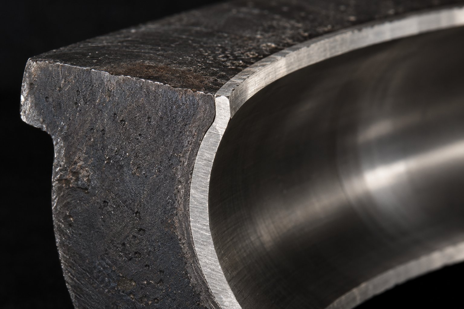
If you crack open a cross-section of a high-quality conical barrel, you will not find a single homogeneous metal. Instead, you will see two distinct layers working together: a thick structural outer shell and a thin, extremely hard inner lining. This is bimetallic construction, and it exists because no single alloy can simultaneously provide the toughness needed to resist external mechanical loads and the hardness needed to survive the abrasive, corrosive environment inside the bore.
The outer shell is typically made from a medium-carbon alloy steel such as 42CrMo (equivalent to AISI 4140). This steel delivers the tensile strength, fatigue resistance, and machinability the barrel body requires — it holds the barrel's shape under clamping loads, supports heater band contact surfaces, and withstands the thermal cycling of daily startups and shutdowns. But 42CrMo alone would erode rapidly under the grinding action of PVC compounds filled with calcium carbonate, titanium dioxide, or wood flour.
That is where the inner lining takes over. Manufactured through centrifugal casting — a process that spins molten alloy inside the heated barrel shell at high speed, allowing centrifugal force to distribute the lining uniformly along the bore — the liner creates a wear surface engineered specifically for the compounds running through it. The internal structure of the liner is manufactured from different mineral compositions depending on the process, and the centrifugal casting method ensures a dense, pore-free bond between the liner and the backing shell.
Three broad families of lining alloys cover most conical extrusion applications:
- Iron-based alloys — The standard choice for processing unfilled or lightly filled PVC dry-blend. These liners offer good abrasion resistance at moderate cost, with typical hardness in the range of 58-65 HRC. They handle the day-to-day wear of rigid PVC pipe and profile production without the premium price of more exotic compositions.
- Nickel-based alloys — Preferred when formulations contain significant levels of abrasive fillers (calcium carbonate at 20%+ loading, for example) or when corrosion resistance is critical. Nickel-based liners resist both mechanical abrasion and the hydrochloric acid that PVC can release during degradation, offering hardness values that often exceed 60 HRC while maintaining better corrosion resistance than iron-based alternatives.
- Tungsten carbide-enriched alloys — The heavy artillery for extreme wear environments. When processing highly abrasive WPC formulations loaded with wood flour and mineral fillers, or running glass-fiber-reinforced compounds, tungsten carbide particles embedded in the liner matrix create a surface that resists even aggressive abrasive attack. As industry specialists note, barrel manufacturers utilizing centrifugally cast alloys with high tungsten carbide content can supply products that provide significantly extended service life.
Hardness ratings — expressed as HRC (Rockwell C scale) or HV (Vickers hardness) — are the primary metric for comparing liner performance. Higher hardness generally means slower wear, but the relationship is not purely linear. A liner that is extremely hard but brittle can crack under thermal shock, and a liner alloy that excels against abrasion may perform poorly against corrosion. Selecting the right lining means matching the alloy family to your specific formulation — not simply choosing the hardest number on the datasheet.
Nitrided Screws and Surface Treatment Options
While the barrel relies on a separate lining material for protection, the screws take a different approach: surface treatment. The base screw is machined from a nitridable alloy steel — commonly 38CrMoAlA or similar grades containing aluminum and chromium that respond well to nitrogen diffusion — and then hardened through a thermochemical process that transforms the surface layer without altering the screw's core toughness.
Gas nitriding is the standard treatment for conical twin screws processing PVC. The process exposes the finished screw to a nitrogen-rich atmosphere at elevated temperatures (typically 950-1070°F), allowing nitrogen atoms to diffuse into the steel surface and form hard chromium nitride compounds. The result is a nitrogen-diffused case — a hardened surface layer measured in Vickers hardness (HV) — that resists the adhesive wear caused by PVC melt dragging across the screw flight surfaces. For steels like AISI 4140, gas nitriding produces reliable surface hardening, while more demanding applications using steels such as Nit135M or H-13 can achieve surface hardness exceeding 70 HRC equivalent — hard enough to withstand even severely abrasive processing conditions.
For longer screws or components requiring selective hardening, ion (plasma) nitriding offers additional control. This variant uses glow-discharge plasma in a vacuum chamber to drive nitrogen ions into the surface, allowing operators to mask specific areas that should not be hardened — bearing journals, spline screw connections, or sealing surfaces, for instance. The ability to selectively harden only the wear-exposed surfaces while leaving coupling zones tough and ductile is a significant engineering advantage, particularly for conical screws where the involute spline shaft connection to the gearbox must retain impact resistance.
Gas nitriding is not always sufficient, though. When the formulation becomes more aggressive, alternative surface treatments step in:
- Gas nitriding — Standard for unfilled and lightly filled PVC; produces a hard nitrogen-diffused case that resists adhesive wear at moderate cost.
- Bimetallic overlay (hardfacing) — Welded-on alloys such as cobalt-based Stellites or nickel-based Colmonoys applied to screw flight tips; suited for calcium carbonate-filled PVC where flight-tip abrasion is the dominant wear mode.
- Tungsten carbide coating — Applied to flight lands for highly abrasive formulations containing wood flour, glass fiber, or heavy mineral loading; delivers maximum abrasion resistance but requires careful application to avoid cracking.
- Chrome plating — Provides a corrosion-resistant barrier against chemically aggressive polymers; useful for PVC compounds with high chloride release potential, though it has different coefficients of thermal expansion than the base steel and may exfoliate at elevated temperatures.
Each treatment involves trade-offs. Hardfacing alloys like Stellites offer excellent mechanical and anti-corrosive properties but — as nitriding specialists have documented — can have comparatively weak adherence to the base screw material if not applied properly. Chrome plating delivers a smooth, corrosion-resistant surface but risks delamination under thermal cycling. The right choice depends on matching the treatment to both the compound chemistry and the operating temperature profile of your specific extrusion process.
How Material Choice Impacts Longevity and Processing Performance
Imagine running a WPC formulation loaded with 40% wood flour through a barrel lined with a standard iron-based alloy and screws with only gas nitriding. The abrasive filler particles act like sandpaper against every surface they contact. Within months, the barrel liner erodes unevenly, screw flight tips lose their edge profile, and the clearance between flights and bore widens. An extruder diagram of the wear pattern would show the heaviest damage concentrated in the compression and metering zones — exactly where pressure and material density peak.
As those clearances grow, the consequences cascade. Melt leaks backward over the screw flights, reducing forward pumping efficiency. The operator increases screw speed to compensate, which raises motor amperage and energy consumption. Barrel temperatures creep upward as the machine works harder to maintain output. Product quality drifts — wall thickness variation in pipe, surface roughness in profiles, inconsistent foam cell structure in board. As plastics processing experts explain, these adjustments are often incremental and go unnoticed until they dramatically impact part quality or productivity.
The fix is not to replace parts more often — it is to specify the right materials from the start. A nickel-based or tungsten carbide barrel liner paired with bimetallic-hardfaced screw flights would handle that same WPC formulation with a fraction of the wear rate. The upfront cost is higher, but the total cost of ownership — factoring in longer service intervals, lower energy consumption, and consistent product quality — drops significantly.
Compatibility between screw and barrel materials matters just as much as the individual selections. Running a very hard barrel lining against an under-protected screw creates an asymmetric wear situation where the softer component degrades rapidly. Softer materials have a greater tendency to gall when contacting harder surfaces, so it is critical to consider the screw flight hardfacing material and its compatibility with the barrel lining alloy. The goal is a balanced wear couple — two surfaces that wear at similar, slow rates rather than one sacrificing itself to protect the other.
Maintaining durable twin screw systems in demanding production environments ultimately comes down to this: every material decision you make at the procurement stage writes the wear story your maintenance team will live with for thousands of operating hours. Get the metallurgy right, and the system rewards you with stable output and predictable service life. Get it wrong, and no amount of process adjustment will compensate for parts that are fundamentally mismatched to the job they are being asked to do. That mismatch, of course, does not exist in isolation — it plays out through the dynamic interactions between every component in the system, where one part's condition directly accelerates or decelerates wear in every part it touches.
How Conical Twin Screw Extruder Parts Interact as a System
A worn screw does not just hurt plasticizing efficiency — it punishes the barrel, overloads the gearbox, and distorts the thermal profile that your heaters are fighting to maintain. This is the reality of durable twin screw systems challenges that most troubleshooting guides miss: every component in a conical extruder exists in a feedback loop with every other component. Change one variable — a slightly eroded flight tip, a sluggish heater band, an overtorqued gearbox — and the consequences ripple through the entire machine. Understanding these interactions is what transforms a parts list into an engineering strategy.
How Screw Design Affects Barrel Wear Patterns
The taper angle, flight geometry, and clearance between the screw flight tip and barrel bore directly determine where and how fast the twin screw and barrel wear together. In a conical system, pressure increases progressively as material moves toward the narrow discharge end. That pressure gradient means the metering zone — where the screws reach their smallest diameter and flight depth is shallowest — concentrates the highest contact forces between the screw flights and the barrel liner.
Picture the melt being squeezed into an ever-tighter space. The narrowing bore amplifies side forces that push the screw flights against the liner wall, and any abrasive filler particles in the compound act as grinding media trapped between two hard surfaces. The result is predictable: barrel liner erosion is almost always heaviest in the last third of the bore, near the discharge. Aggressive screw flight designs — sharp flight tip edges, tight initial clearances, or steep compression profiles — accelerate this pattern further. A screw designed for maximum output will extract that output at the barrel's expense if the liner metallurgy cannot absorb the pressure differential the geometry creates.
As that clearance widens from wear, melt leaks backward over the flight tips. The processor compensates by increasing screw speed, which drives motor amperage up, generates more frictional heat, and — critically — raises discharge temperature because the thicker melt film on the barrel wall reduces heat-transfer efficiency. One worn surface triggers a cascade that degrades every performance metric simultaneously.
Gearbox Capacity and Its Limits on Screw Torque
The gearbox is the torque bottleneck in every conical extruder — and the conical geometry makes that bottleneck especially critical. As the tapered feed screws push material into narrowing channels, they generate substantial axial thrust forces directed rearward into the gearbox. The thrust bearing arrangement must absorb every newton of that load continuously, hour after hour.
Screw designs that demand torque beyond the gearbox's continuous-duty capacity do not simply reduce gearbox life — they trigger a specific failure sequence. Thrust bearing capacity often limits gearbox life before torque capacity does, because an undersized thrust bearing fails through fatigue even when the gear train handles the rotational load without issue. Peak torque during startup with cold, unplasticized material can exceed steady-state running torque by 20-40%, and if the gearbox is sized only for running conditions, those startup spikes chip away at bearing life cycle after cycle.
This relationship constrains maximum screw speed and output. You cannot simply install a more aggressive screw to boost throughput without verifying that the gearbox can absorb the resulting thrust increase. Running the gearbox at 80% of its continuous torque rating — not 80% of its peak rating — provides the margin needed to accommodate process variations, cold starts, and the gradual torque creep that occurs as screw and barrel wear reduces pumping efficiency and the operator dials up RPM to compensate.
Heating Zone Configuration and Melt Quality
Barrel heaters do not operate independently of screw compression — they work in tandem with it. The number, placement, and wattage of heaters in each zone interact with the screw's mechanical compression to determine melt temperature uniformity at the die. Get the balance wrong, and no amount of PID tuning will fix the result.
In a conical extruder, the feed zone typically requires cooling rather than heating — water channels in the barrel wall pull heat away to prevent premature softening and bridging. The compression and transition zones need carefully staged heating that supplements the rising shear energy from the narrowing screw channels. The metering zone, where the melt should be fully homogeneous, often requires precise temperature trimming to fine-tune viscosity before the material exits through the die.
Thermocouple placement is integral to this system. As Davis-Standard's engineering team explains, a single thermocouple configuration introduces a time lag before the barrel temperature stabilizes on the setpoint, causing fluctuations. Dual-thermocouple configurations — one in the barrel wall, one at the heat source — allow the PID controller to calculate both the current state and the rate of change, dramatically tightening temperature control. When a heater band burns out in the compression zone, the screws' mechanical compression still generates heat — but unevenly, creating hot spots that degrade PVC locally while leaving adjacent areas under-plasticized. The defect shows up in the product as inconsistent gelation or surface imperfections that seem random but trace directly back to a single failed heating element.
No single part determines extruder performance — output quality emerges from the interaction between screw geometry, barrel condition, heating configuration, and gearbox capacity working as an integrated system.
This systems perspective reframes how you should think about maintenance and troubleshooting. A rising discharge temperature is not just a heater problem — it could be a worn screw forcing higher RPM, a degraded barrel liner reducing heat transfer, or a gearbox operating at its thrust limit and constraining the speed range available for process adjustment. Diagnosing the root cause requires evaluating the full interaction chain, not just the component closest to the symptom. And that diagnostic skill depends on knowing exactly how each part fails — the specific wear patterns, stress distributions, and failure modes unique to conical geometry.
Wear Patterns and Failure Analysis in Conical Twin-Screw Extruder Geometry
Knowing that parts interact as a system is essential — but predicting where those interactions will eventually cause failure requires a deeper look at the stress physics unique to tapered screw and barrel designs. A parallel twin screw extruder machine distributes pressure through modular screw element selection, giving engineers considerable control over where forces concentrate. A conical system offers no such luxury. The converging geometry dictates the pressure profile, and every wear pattern follows from that fixed geometry. If you want to catch problems before they become catastrophic, you need to understand the stress map that the taper itself creates.
Unique Stress Distributions in Tapered Screw and Barrel Systems
Imagine squeezing toothpaste through a tube — the narrower the opening, the higher the pressure required to push material through. A conical twin screw extruder operates on a similar principle. As the bore converges from the wide feed end to the narrow discharge, the available channel volume shrinks continuously, and internal melt pressure rises progressively along the screw length. This non-uniform pressure distribution is fundamentally different from what you see in a parallel machine, where engineers can redistribute pressure zones by swapping kneading blocks, adjusting screw pitch, or changing element sequences.
In conical systems, the pressure gradient is locked into the hardware. Research into calender gap forces in counterrotating twin screw extruders has demonstrated just how significant these forces become. In closely intermeshing counter-rotating designs, large separating forces develop in the calender gap — the narrow region where the core of one screw faces the flight tip of the other. These forces push the screws laterally toward the barrel wall, and the resulting screw deflection concentrates abrasive contact in a specific angular zone. Experimental measurements on a 55 mm extruder processing rigid PVC showed that separating forces exceeded one metric ton in the metering zone alone, with the resultant force direction falling at approximately 30 degrees from the vertical axis.
What does that mean practically? It means the barrel liner does not wear uniformly around its circumference. Instead, maximum bore erosion occurs in a band roughly between the 30-degree and 60-degree positions from vertical — often described in the industry as the "ten o'clock and two o'clock" positions. Bore diameter measurements taken on a 90 mm nitrided barrel that ran a highly filled PVC formulation for over 10,000 hours confirmed this pattern, with maximum diameter increase recorded at the 135-degree angular position, approximately 45 degrees from vertical. The wear was not random. It was dictated by the calender-gap forces inherent to the intermeshing geometry.
This wear concentration intensifies toward the discharge end of the barrel for a straightforward reason: pressure is highest where the bore is narrowest. The metering zone barrel liner and the screw flight tips at the small-diameter end experience the most aggressive combination of high melt pressure, high contact force, and abrasive filler action. If your formulation includes calcium carbonate, wood flour, or titanium dioxide at significant loadings, the metering-zone liner is where you will see the first signs of bore ovality and clearance growth — often months before the feed or compression sections show measurable wear.
Gravity adds another layer of complexity in larger machines. A four-meter-long screw weighing several hundred kilograms acts like a cantilevered beam, sagging under its own weight. That gravitational deflection combines with the calender-gap separating force to shift the resultant force angle further away from the vertical — meaning the barrel wear band migrates outward compared to what smaller laboratory extruders predict. Operators running large-diameter conical extruders should expect the worst wear to appear at a slightly wider angular position than the textbook 30-degree range.
Common Failure Modes in Drive and Coupling Components
The screw-barrel interface gets most of the attention during wear inspections, but the components connecting the gearbox to the screws endure punishing conditions of their own. Every newton of torque and every newton of axial thrust passes through the coupling interface — typically a spline or hex shaft joint — making it one of the most failure-prone connections in the entire twin screw extruder machine.
Consider what happens during a typical production cycle. The screws start cold, and the gearbox delivers a torque spike to begin rotating them against the friction of unplasticized PVC powder. As the machine warms up, torque drops to a steady-state level but never stays perfectly constant — every variation in feed rate, material bulk density, or downstream pressure sends a torque pulse back through the screw shafts into the coupling. This torque cycling fatigues the contact surfaces over time. On a hexagonal shaft connection, the flat-to-flat contact creates stress concentrations at the corners of the hex, leading to localized deformation that eventually manifests as backlash and vibration. Involute spline shaft designs distribute that same torque across multiple curved tooth surfaces, reducing peak stress at any single point — which is why high-output machines increasingly favor involute splines over simpler hex connections.
Misalignment compounds every coupling failure mode. Even a fraction of a degree of angular offset between the gearbox output shaft and the screw shaft introduces bending loads that the coupling was never designed to carry. Over thousands of hours, those bending loads cause shaft fatigue — micro-cracks initiating at the root of spline teeth or at keyway corners, propagating cycle by cycle until the shaft fractures. Misalignment also produces uneven wear across the spline tooth faces: one side of each tooth carries a disproportionate share of the load, wearing faster and accelerating the onset of backlash.
The following list maps the most common failure modes across each major component category in a conical system:
- Screws: Flight tip wear (abrasive erosion reduces flight OD, widening barrel clearance); root cracking (fatigue fractures at the base of flight roots, especially in the high-pressure metering zone where cyclic bending stress is greatest).
- Barrel: Liner erosion (progressive material loss concentrated between 30 and 60 degrees from vertical due to calender-gap separating forces); bore ovality (non-uniform diameter growth that destroys the precision cylindrical profile needed for tight screw-barrel clearance).
- Gearbox coupling: Spline wear (surface material loss on tooth flanks from torque cycling, leading to backlash and vibration); shaft fatigue (crack initiation at stress risers — keyways, spline roots, or hex corners — propagating under cyclic bending from misalignment).
- Heating system: Heater burnout (open-circuit failure in band or cartridge heaters from thermal cycling fatigue, creating dead zones in the barrel temperature profile); thermocouple drift (gradual loss of measurement accuracy as the sensing junction degrades, causing PID controllers to regulate to incorrect temperatures).
Each of these failure modes develops gradually. The danger is not the failure itself — it is the long period of degraded performance that precedes it, during which energy consumption rises, product quality drifts, and the operator compensates with process adjustments that mask the underlying problem.
Reading Wear Indicators Before Catastrophic Failure
The good news? Every one of these failure modes broadcasts warning signs — if you know what to look for. Catching those signals early is the difference between a planned maintenance window and an emergency shutdown that halts production for days.
Start with motor amperage. A healthy conical extruder running a consistent formulation at a fixed screw speed draws a predictable, stable current. As screw flight tips erode and barrel clearance widens, melt leaks backward over the flights, reducing forward pumping efficiency. The operator — or the control system — increases screw RPM to maintain output. That RPM increase draws more current. Research into extruder wear diagnostics confirms that worn working elements cause measurably higher current draw compared to new components running the same material at the same speed. Tracking motor amperage trends over weeks and months creates a wear curve you can use to predict when clearance will exceed acceptable limits.
Melt temperature at the die provides a second diagnostic signal. When screw-barrel clearance grows, the thicker melt film on the barrel wall acts as an insulator, reducing heat-transfer efficiency. At the same time, the higher screw RPM needed to compensate for lost pumping capacity generates additional shear heat. The combined effect is a rising discharge temperature at constant heater setpoints. If your metering-zone melt temperature creeps upward by 5-10°F over several weeks without any recipe or setpoint change, worn screw flights and barrel liner erosion should be the first suspects.
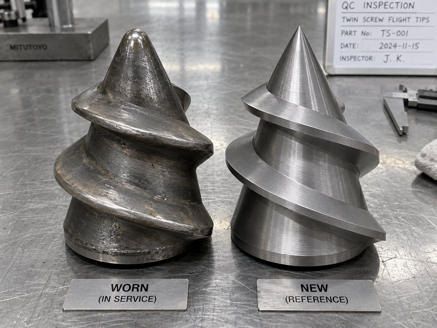
Visual inspection of pulled screws tells the rest of the story. Healthy flight tips display sharp, well-defined edges with a consistent profile from feed to discharge. Worn flights show rounded, polished tips — particularly at the narrow metering end — and you may see scoring or galling marks on the flight flanks that indicate metal-to-metal contact with the barrel bore. Measure flight outer diameter at multiple points along the screw taper using a micrometer and compare to the original manufacturing dimensions. A diameter reduction of just 0.1-0.2 mm per side at the flight tip can translate into a significant clearance increase that measurably impacts plasticizing performance.
Beyond the screws, check coupling surfaces during every pull inspection. Run a fingernail across the spline teeth or hex flats — any perceptible step wear, ridging, or discoloration indicates torque-cycling damage. Measure gearbox thrust bearing axial play with a dial indicator; increasing play signals bearing fatigue that will eventually cascade into gear mesh misalignment and accelerated tooth wear. And inspect heater bands for discoloration, hot spots, or deformation — a band heater that has visibly darkened or warped is operating under stress and approaching burnout.
The underlying principle is simple: every conical twin screw extruder part leaves a trail of evidence as it wears. Motor data, temperature trends, dimensional measurements, and visual surface condition collectively build a diagnostic picture that — when read systematically — tells you not just that something is wearing, but what is wearing, where the damage is concentrated, and how much life remains before replacement becomes unavoidable. That diagnostic clarity sets the stage for the next critical step: choosing the right replacement parts matched precisely to your processing application.
Selecting Replacement Parts by Processing Application
Diagnostic clarity is only half the equation. Once you know a part needs replacing, the next question — and the one that separates a smooth recovery from a repeat failure — is which replacement part actually matches your specific extrusion application. A barrel liner that performs beautifully in rigid PVC pipe production may erode in months running a heavily filled WPC formulation. A screw geometry optimized for foam board will starve a high-output pipe die. The application dictates the specification, not the other way around.
Matching Parts to PVC Pipe and Profile Extrusion Requirements
Rigid PVC pipe and profile extrusion share a common demand: tight melt temperature control with minimal shear-induced degradation. PVC's processing temperature window sits dangerously close to its decomposition point, so the screw design must deliver thorough fusion without generating excessive frictional heat. For pipe production, that typically means screw geometries with moderate compression ratios, relatively conservative flight depths, and taper angles that build pressure gradually through the compression zone.
Profile extrusion adds a wrinkle. Complex cross-sections — window frames, siding panels, multi-cavity profiles — require higher melt homogeneity and tighter viscosity control than simple round pipe. Screw shafts for profile applications often feature slightly deeper flights in the metering zone to extend residence time and improve melt uniformity. Barrel liners for both applications run standard iron-based bimetallic alloys when the formulation uses minimal filler. The feeder screws at the intake must handle low-bulk-density PVC dry-blend efficiently, making deep-cut, wide-pitch feed section geometry essential for consistent volumetric throughput.
Flight pitch also differs between the two. Pipe extrusion prioritizes high volumetric output at steady pressure, favoring a slightly more aggressive pitch progression. Profile extrusion benefits from a gentler pitch transition that trades raw throughput for finer control over melt quality — because a surface defect invisible on the inside wall of a buried water pipe becomes a reject-worthy flaw on a visible window frame.
Selecting Parts for Foam Board and WPC Applications
Shift from standard rigid PVC to foam board or WPC extrusion, and the wear environment changes dramatically. Foam board formulations contain chemical blowing agents that require precise temperature management — too much shear heat triggers premature decomposition of the blowing agent, producing oversized, irregular cells instead of the fine, uniform foam structure the product demands. Screw designs for foam board typically use lower compression ratios than pipe screws, with shallower flight profiles in the transition zone to minimize shear energy input.
WPC formulations introduce a different challenge entirely: abrasive filler content. Wood flour loadings of 30-50% act like sandpaper against every surface they contact. Calcium carbonate, often added as a secondary filler, compounds the abrasive attack. Standard gas-nitrided screws and iron-based barrel liners simply cannot survive these conditions at reasonable service intervals. This is where bimetallic barrel liners with nickel-based or tungsten carbide-enriched alloys become non-negotiable. On the screw side, hardfaced flight tips — cobalt-based or tungsten carbide overlays — protect the areas experiencing the heaviest abrasive contact.
As screw design research for thermoplastic composites documents, abrasive fillers cause wear that begins in the feed section where material is still in powder or pellet form and composites near the pellet surface rub against unprotected steel. Once the resin melts, a lubrication film reduces direct abrasive contact — but in a conical system, the converging geometry continuously re-exposes fresh barrel liner surface to high-pressure filler contact all the way through the metering zone. Both ends of the machine take a beating, and parts must be specified accordingly.
The cost premium for abrasion-resistant components pays for itself quickly. A double screw extruder machine running WPC on standard-grade parts might need screw and barrel replacement every 2,000-3,000 hours. The same machine fitted with tungsten carbide-enriched liners and hardfaced screws can push well past 8,000 hours — cutting not only parts cost but also the production downtime associated with every changeover.
How to Interpret Part Specifications and Datasheets
Whether you are sourcing parts for pipe, profile, foam board, or WPC, the replacement decision ultimately comes down to reading and comparing specifications. And this is where many buyers stumble — not because the data is hidden, but because the numbers mean nothing without context. Here is how to decode the key parameters you will encounter on any conical twin screw barrel or screw datasheet.
| Specification Parameter | What It Tells You | Why It Matters for Your Application |
|---|---|---|
| Screw Diameter Range (Large End / Small End) | Defines the physical size of the taper — e.g., 92/188 means 92 mm at the metering end, 188 mm at the feed end | Must match your extruder frame exactly; determines volumetric capacity and compression ratio |
| L/D Ratio | Ratio of effective screw length to a reference diameter; indicates processing length available | Higher L/D provides more residence time and gentler compression — critical for thermally sensitive PVC and foam applications |
| Taper Angle | The angle of convergence from feed to discharge | Controls the geometric compression ratio; steeper angles generate more compression per unit length, affecting shear heat and pressure buildup |
| Barrel Bore Tolerances | Precision of the internal bore dimensions at specified measurement points along the taper | Tighter tolerances maintain optimal screw-barrel clearance, directly governing plasticizing efficiency and melt leakage rates |
| Liner Material Grade | Alloy family and composition of the bimetallic barrel liner | Determines abrasion and corrosion resistance; must be matched to your filler type and loading level — iron-based for standard PVC, nickel or tungsten carbide for filled or WPC formulations |
| Liner Hardness (HRC / HV) | Surface hardness of the barrel liner after centrifugal casting | Higher hardness resists abrasive wear from fillers; typical values range from 58-65 HRC for iron-based to 72+ HRC for tungsten carbide-enriched alloys |
| Screw Surface Treatment | Type of hardening applied to the screw — nitriding, hardfacing, chrome plating, or tungsten carbide coating | Must complement the barrel liner to create a balanced wear couple; mismatched hardness accelerates degradation of the softer component |
| Screw Nitriding Depth | Thickness of the nitrogen-diffused hardened case, typically 0.4-0.7 mm | Deeper case extends service life before the softer base metal is exposed; once the nitrided layer wears through, erosion accelerates dramatically |
Reading these specifications in isolation tells you whether a part fits your machine. Reading them together tells you whether the part will survive your process. A barrel with a tight bore tolerance and a premium tungsten carbide liner paired with a screw whose nitriding depth is only 0.4 mm creates an imbalance — the barrel outlasts the screw by thousands of hours, forcing a premature screw replacement that takes the machine offline while the barrel still has life left. The smartest procurement approach matches screw and barrel wear lives so both components reach end-of-service at roughly the same interval, allowing a single planned shutdown for a complete changeover.
Manufacturers who specialize in conical systems understand this matching logic. NANHAIYA, for example, engineers custom conical twin screw barrels specifically matched to application requirements — PVC pipe, PVC profile, PVC board, foam board, and WPC extrusion — with liner materials and screw geometries selected to balance wear life across the full screw-barrel assembly. When evaluating replacement options, look for suppliers who ask about your formulation, filler loading, and production targets before quoting a part number. A vendor who specifies by application rather than just by machine model is far more likely to deliver parts that perform in your actual operating environment.
Specification literacy and application-matched sourcing get the right parts into your extruder. Keeping them running at peak performance, though, requires a disciplined inspection and maintenance routine — one that catches wear progression early enough to schedule replacements on your terms, not the machine's.
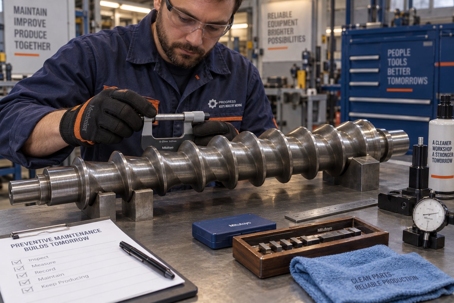
Maintenance and Inspection Checklist for Extruder Screws and Barrels
Specification literacy gets the right parts into your machine. A disciplined inspection routine keeps them there as long as physically possible — and tells you exactly when "as long as possible" has arrived. The difference between a plant that replaces screw and barrel sets on a predictable schedule and one that scrambles through emergency shutdowns almost always comes down to how consistently the maintenance team measures, records, and trends the condition of every critical component.
What follows is a component-by-component inspection framework built specifically for conical twin screw extruders. It goes deeper than generic extruder maintenance advice because conical geometry creates unique wear patterns — concentrated at the narrow metering end, distributed asymmetrically around the bore circumference, and driven by calender-gap forces that standard checklists never account for.
Screw and Barrel Inspection Intervals and Methods
The extruder screw barrel assembly is where wear hits hardest and hides longest. You cannot see clearance growth from the outside of the machine, and by the time output quality visibly suffers, you have already been running inefficiently for weeks or months. The only reliable approach is periodic pull-and-measure inspection — removing the screws, cleaning both the screws and the barrel bore, and taking precise dimensional readings at multiple points along the taper.
For the screws, measure flight outer diameter at every other flight using a micrometer, starting from the large feed end and working toward the narrow discharge tip. Pay special attention to the metering zone flights — this is where pressure peaks and abrasive contact is most aggressive. Record the root diameter between every other flight through both the feed and metering sections. As Arlington Machinery's inspection protocols detail, a technician should also assess the condition of the root for washouts and examine the nose threads and shank for blemishes — faults that can hide easily in the intricate geometry of the screw.
For the barrel, use a dial bore gauge and micrometer to take measurements every two to three inches down the bore after it has been purged, cleaned with brass gauze, and cooled to room temperature. Taking small, frequent measurements picks up nuances and localized imperfections that wider spacing would miss — especially the asymmetric wear patterns typical of conical bores, where maximum erosion concentrates between the 30-degree and 60-degree positions from vertical due to calender-gap separating forces. Visually inspect the bore as well: the heaviest wear is typically found near the middle to discharge sections where polymer melting and pressure peak.
The critical metric is screw-barrel clearance — the gap between the screw flight tip OD and the barrel bore ID at corresponding points along the taper. When this clearance exceeds the manufacturer's recommended tolerance, melt leaks backward over the flights, plasticizing efficiency drops, and output quality suffers. Industry practice recommends performing these measurements every 500 to 1,000 operating hours and tracking clearance growth over time. The trend line — not any single reading — is what tells you when replacement is approaching.
Gearbox, Drive, and Heating System Checks
Screws and barrels absorb the most dramatic wear, but the gearbox, drive couplings, and thermal management system fail in ways that are equally expensive and often harder to diagnose without a structured routine. A gearbox bearing that seizes or a heater band that burns out mid-run does not just stop production — it can damage adjacent components and turn a single-part replacement into a multi-system rebuild.
Gearbox oil analysis is your first line of defense. Sample the oil regularly and check for color changes, metallic particles, unusual smell, and contamination — all early indicators of internal gear or bearing degradation. Circulating-oil systems should also have their pressure verified and magnetic filters cleaned on a set schedule. Thrust bearing axial play measurement, performed with a dial indicator on the output shaft, reveals whether bearing fatigue is developing before it cascades into gear mesh misalignment. As structured maintenance research emphasizes, systematic oil checks and vibration monitoring provide early warning that enables planned replacement during scheduled downtime rather than emergency intervention.
Coupling inspections — whether your machine uses an involute spline or hex shaft connection — should happen every time the screws are pulled. Run a fingertip across the spline teeth or hex flats to feel for step wear, ridging, or surface galling. Any perceptible deformation signals torque-cycling damage that will eventually introduce backlash and vibration into the entire drive train.
Heater and thermocouple checks round out the system. Test heater band resistance with a multimeter to identify elements approaching burnout — a band whose resistance has drifted significantly from its nameplate value is operating under stress. Verify thermocouple accuracy by cross-referencing readings against a calibrated reference sensor. Weekly cross-verification is recommended for heavy-duty lines, with formal calibration against reference standards every three months — and more frequently if you routinely run high-temperature or abrasive-filled materials.
The following checklist organizes every inspection into a single, sequential routine you can hand to any technician on any shift:
- Screw flight measurement — Measure flight OD at every other flight with a micrometer; compare against original manufacturing dimensions and previous readings to track diameter loss.
- Barrel bore gauging — Use a dial bore gauge every two to three inches along the taper after purging and cooling; record measurements at multiple angular positions to detect asymmetric wear.
- Screw-barrel clearance calculation — Subtract screw flight OD from barrel bore ID at each corresponding point; flag any location where clearance exceeds the manufacturer's specified tolerance.
- Gearbox oil sampling — Draw an oil sample and inspect for color change, metallic particles, and contamination; send for laboratory analysis if visual indicators are ambiguous.
- Thrust bearing axial play check — Mount a dial indicator on the gearbox output shaft and measure axial movement; compare against baseline and trend over time.
- Coupling spline inspection — Visually and tactilely examine spline teeth or hex shaft flats for step wear, ridging, galling, or discoloration indicating torque-cycling fatigue.
- Heater resistance testing — Measure resistance of each barrel heater band or cartridge with a multimeter; replace any element whose resistance deviates significantly from nameplate specification.
- Thermocouple accuracy verification — Cross-reference each thermocouple reading against a calibrated reference sensor; recalibrate or replace units showing drift beyond acceptable limits.
- Feed throat liner condition — Inspect for cracks, washout spots, scoring, and cooling passage blockages that could cause material bridging and feed inconsistency.
- Die and adapter wear surfaces — Check flow channels for scoring, buildup, or dead spots where PVC could stagnate and degrade; verify die bolt torque and adapter sealing surfaces.
Each item on this list catches a specific failure mode before it cascades into secondary damage. Screw flight measurement and barrel bore gauging together reveal the clearance growth that drives rising motor amperage and falling plasticizing efficiency. Gearbox oil sampling and thrust bearing checks intercept bearing fatigue weeks before a seizure event. Heater and thermocouple verification prevents the dead zones and temperature drift that create localized PVC degradation and inconsistent product quality.
Timing matters as much as technique. Pull-and-measure inspections every 500 to 1,000 operating hours establish the trend data you need to forecast replacement windows accurately. Gearbox oil analysis, heater resistance testing, and thermocouple verification fit naturally into monthly or quarterly maintenance schedules. Daily monitoring of motor amperage, zone temperatures, and melt pressure at the die provides the real-time signal layer that flags developing problems between formal inspections.
When barrel bore gauging reveals liner wear beyond acceptable tolerances, the priority shifts from monitoring to action. Sourcing a precision-manufactured replacement barrel — one whose liner material, bore tolerances, and taper geometry are matched to your specific formulation and extruder model — is critical for restoring stable plasticizing performance. NANHAIYA's conical twin screw barrels, engineered for PVC pipe, profile, board, foam board, and WPC extrusion applications, offer an option for manufacturers who need custom or replacement barrels built to the application-specific liner and dimensional standards that consistent production demands.
Ultimately, every concept explored in this article — from taper-angle physics and bimetallic metallurgy to system-level interactions and zone-specific wear — converges on one practical outcome: keeping your conical twin screw extruder running at peak efficiency for as long as possible, and knowing exactly when and how to restore it when wear finally wins. The checklist above is your operational bridge between understanding why parts wear and controlling when they get replaced. Use it consistently, trend the data over time, and you will stop reacting to failures and start predicting them.
Frequently Asked Questions About Conical Twin Screw Extruder Parts
1. What are the main parts of a conical twin screw extruder?
A conical twin screw extruder consists of several core subsystems. The screw and barrel assembly includes tapered twin screws, a converging-bore bimetallic barrel, a feed throat liner, barrel liner sleeves, and a breaker plate. The drive train features a specialized gearbox with thrust bearings, gear sets, and a coupling interface — either an involute spline or hexagonal shaft — that transfers torque to the screws. The thermal management system includes band or cartridge heaters, thermocouples, and cooling channels in the feed section. Finally, the discharge assembly comprises a screen pack, adapter, and die head. Auxiliary components such as barrel alignment pins, support cradles, clamping hardware, and adapter pieces are also critical for maintaining system integrity and alignment during operation.
2. What is the difference between conical and parallel twin screw extruder parts?
The fundamental difference lies in geometry and construction philosophy. Conical twin screws taper from a large feed-end diameter to a smaller discharge-end diameter, creating built-in compression through shape alone. Parallel screws maintain a constant diameter and rely on modular segmented elements — kneading blocks, mixing discs, and varied-pitch flights — stacked on a spline shaft to achieve compression and mixing. Conical barrels use a converging bore, while parallel barrels have a uniform figure-eight bore. Conical screws are manufactured as one-piece units and replaced as matched screw-barrel pairs, whereas parallel screws allow element-by-element swaps. Conical systems typically excel in PVC pipe, profile, and board extrusion at lower speeds (30-150 RPM), while parallel systems suit high-speed compounding and reactive extrusion at 400-900 RPM.
3. Why do conical twin screw extruder barrels wear out faster in certain zones?
Barrel wear in conical extruders is driven by the converging geometry itself. As material moves from the wide feed end toward the narrow discharge, melt pressure increases progressively. The metering zone — where the bore is narrowest and pressure is highest — experiences the most aggressive combination of high contact force and abrasive filler action. Additionally, calender-gap separating forces in closely intermeshing counter-rotating screws push the screw flights laterally against the barrel wall, concentrating erosion asymmetrically between roughly 30 and 60 degrees from vertical. Formulations containing abrasive fillers like calcium carbonate or wood flour intensify this effect. Monitoring bore diameter at multiple angular positions during scheduled inspections helps detect this pattern early before clearance growth degrades plasticizing efficiency.
4. How often should conical twin screw extruder parts be inspected?
Industry best practice recommends pull-and-measure inspections of screws and barrel bore every 500 to 1,000 operating hours. During these inspections, technicians should measure screw flight outer diameter at every other flight using a micrometer, gauge the barrel bore every two to three inches along the taper at multiple angular positions, and calculate screw-barrel clearance at each corresponding point. Gearbox oil sampling, thrust bearing axial play checks, and coupling spline inspections should align with monthly or quarterly maintenance schedules. Heater resistance testing and thermocouple accuracy verification are recommended weekly for heavy-duty production lines, with formal calibration every three months. Daily monitoring of motor amperage, zone temperatures, and melt pressure provides real-time early warning between formal inspections.
5. What barrel liner material should I choose for PVC and WPC extrusion?
The right liner material depends entirely on your formulation and filler loading. For standard unfilled or lightly filled rigid PVC dry-blend used in pipe and profile production, iron-based bimetallic alloys (typically 58-65 HRC) offer solid abrasion resistance at moderate cost. When formulations contain significant levels of calcium carbonate (20%+ loading) or require enhanced corrosion resistance, nickel-based alloys provide superior performance with hardness often exceeding 60 HRC. For heavily abrasive WPC formulations loaded with 30-50% wood flour or mineral fillers, tungsten carbide-enriched liners (72+ HRC) deliver maximum service life. Manufacturers like NANHAIYA engineer custom conical twin screw barrels with application-specific liner materials matched to PVC pipe, profile, board, foam board, and WPC extrusion requirements, ensuring balanced wear life across the entire screw-barrel assembly.
Written by
Nanhaiya Technical Team
Zhoushan Nanhaiya Plastic Machinery Co., Ltd.
The Nanhaiya technical team supports screw and barrel manufacturing projects through application review, technical communication, custom manufacturing coordination, and production and quality control.
Discuss Your Application
Related Articles
More insights on screw barrel technology and plastics processing.
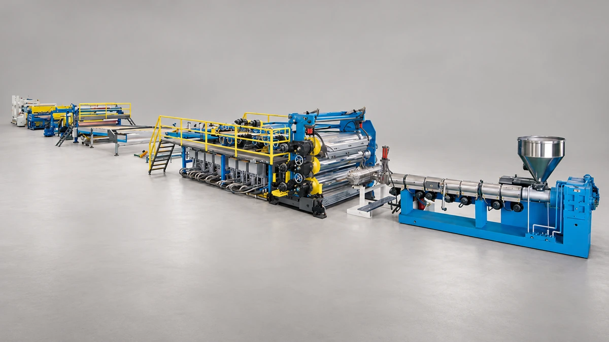
What No Supplier Tells You About Your Pet Sheet Extrusion Line
Oct 28, 2026
Learn what suppliers won't tell you about your PET sheet extrusion line — IV management, APET vs CPET setup, rPET processing, defect fixes, and buyer evaluation tips.
Read Article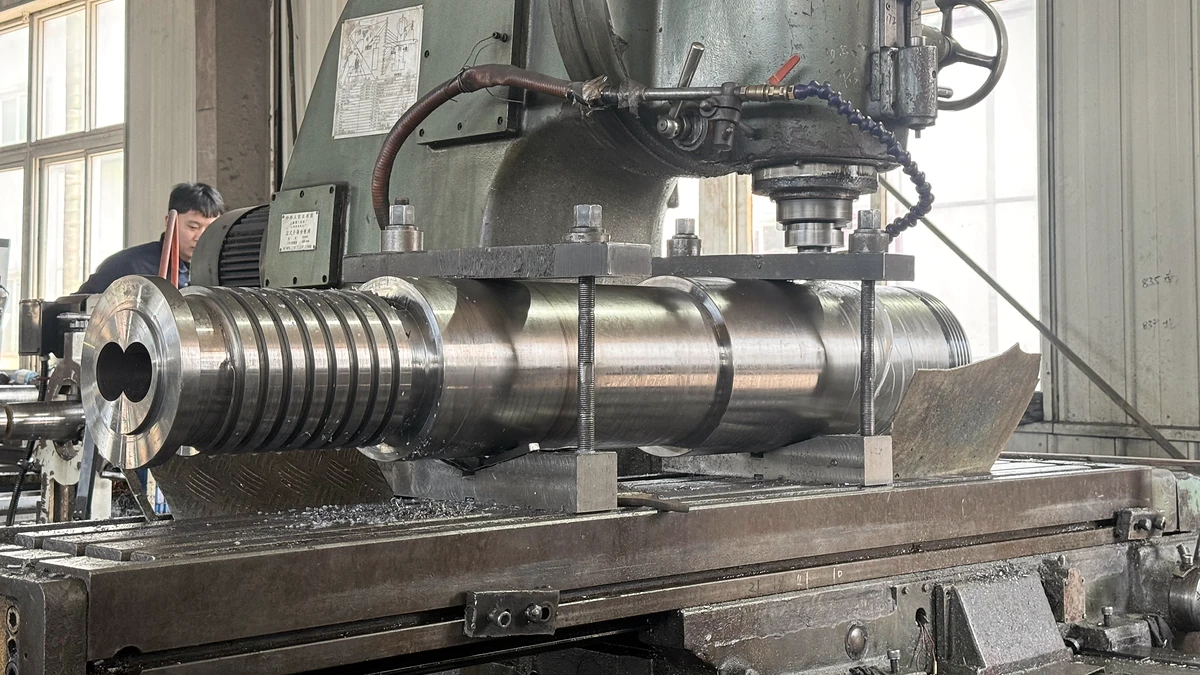
Extruder Barrel Price Decoded: What Suppliers Won't Tell You
Oct 26, 2026
Extruder barrel price guide covering cost drivers, material tiers, geographic pricing, OEM vs. aftermarket options, and total ownership cost to help buyers compare quotes smartly.
Read Article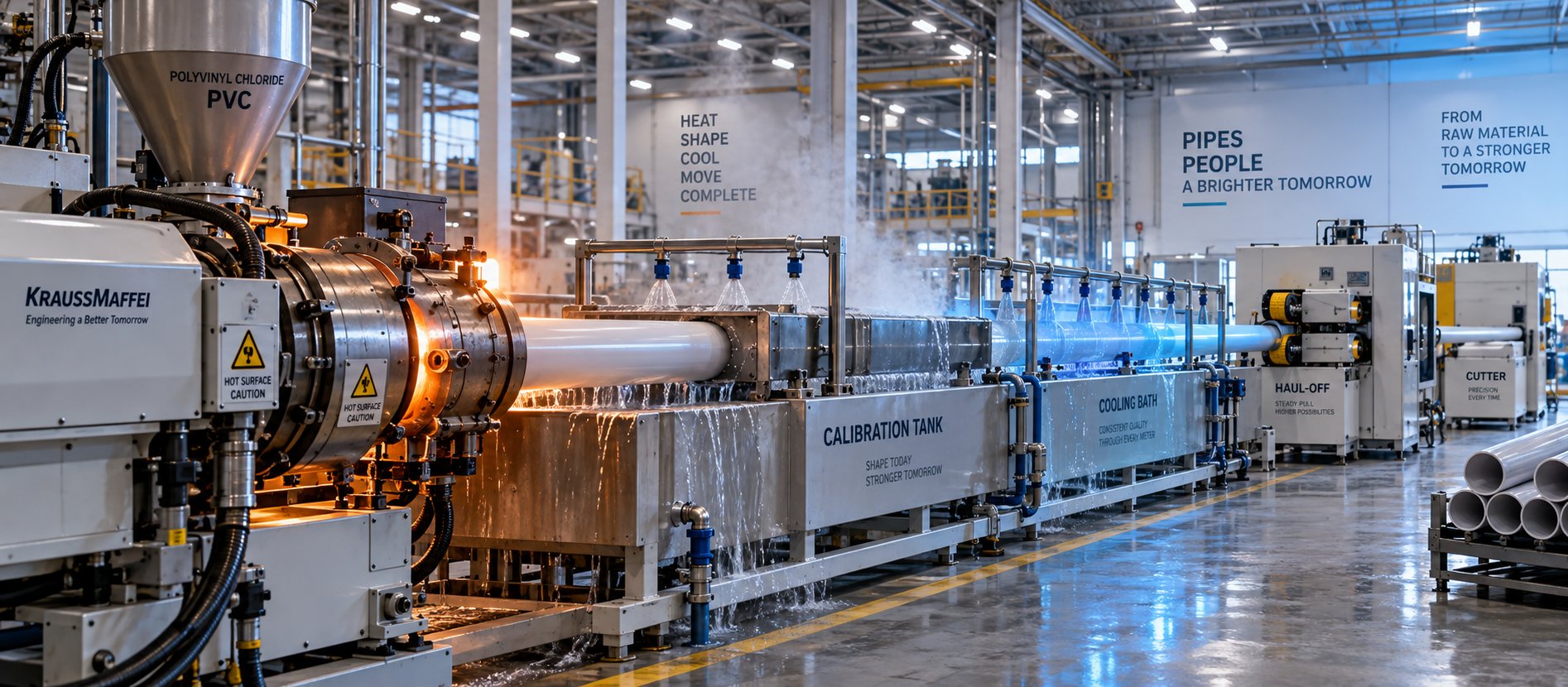
PVC Pipe Making Machine: What No Supplier Will Tell You First
Oct 21, 2026
Learn what a PVC pipe making machine really includes, how each component works, extruder types compared, maintenance schedules, defect fixes, and buying tips.
Read ArticleLooking for something else?
Search by material, symptom or product and jump straight to the relevant page.
These are navigation suggestions based on keyword matching — not a quotation, not a delivery commitment, and not a substitute for engineering review. Final specification is confirmed by our engineers against your drawings and processed material.
Need help with screw barrel selection?
Share your machine model, processed material and application. Our team can help with pricing and technical support.