

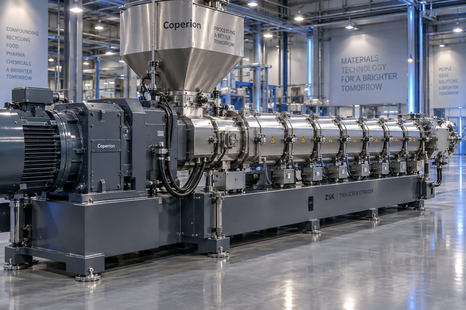
什么是并联双螺杆挤出机?为什么它在加工领域占据主导地位?
如果你问十位工程师如何描述双螺杆挤出机,你很可能会得到十个略有不同的答案。有些人会想到用于PVC管材的锥形装置,有些人则会想到通用的混合设备。但事实上,一种特定的结构已经悄然主导了现代聚合物加工,而网上大多数技术资料仅仅触及了其工作原理的皮毛。
定义平行双螺杆挤出机
平行双螺杆挤出机的核心部件是两个直径相同的啮合螺杆,它们并排安装在一个带有两个平行孔的圆柱形料筒内。这两个螺杆可以同向旋转(同向旋转)或反向旋转(反向旋转)。与锥形设计中螺杆从较大的进料端逐渐变细到较小的出料端不同,平行双螺杆从进料端到出料端都保持着一致的直径。
平行双螺杆挤出机是一种连续加工机器,其特点是两个直径相同的啮合螺杆在八字形平行筒体孔内旋转,用于输送、熔化、混合和脱挥发分聚合物和添加剂,并能精确控制剪切力、停留时间和产量。
这种区别的重要性远超大多数人的想象。统一的螺杆几何形状使得模块化元件系统成为可能,各个输送、捏合和混合部件可以沿螺杆轴重新排列,以应对几乎任何加工挑战。正是这种灵活性,使得平行双螺杆挤出机成为全球混炼、母料生产、反应挤出和塑料回收领域的主力设备。
为什么并行配置在现代处理中至关重要
那么,是什么让这种双螺杆挤出机布局成为行业标准呢?主要有三项工程优势:
- 模块化螺杆设计:分段式螺杆元件可滑入同一根轴上,操作人员无需更换整个螺杆即可重新配置机器,以适应不同的材料或配方。今天针对色母粒优化的配置,明天即可重新调整以适应玻璃纤维增强复合材料。
- 自清洁几何结构:在同向旋转的平行双螺杆挤出机中,啮合区内的表面速度方向相反。这会将物料从一个螺杆刮到另一个螺杆,防止物料堆积,降低物料劣化风险,并形成紧密的先进先出停留时间分布。
- Precise process control: Because the extruder for polymer applications operates in starve-fed mode, screw speed and feed rate are decoupled. Engineers can independently adjust shear intensity, throughput, and energy input rather than forcing trade-offs between them.
These attributes explain why the co-rotating intermeshing twin screw extruder machine dominates compounding, devolatilization, and chemical reaction applications across plastics, food, and even pharmaceutical manufacturing. The counter-rotating parallel variant fills its own niche where high-pressure conveying and narrow residence time windows are priorities, but the co-rotating design accounts for the vast majority of new installations in polymer compounding.
Understanding these fundamentals is just the starting point. The real performance differences between a parallel and conical layout, and the engineering decisions that follow from choosing one over the other, run far deeper than barrel shape alone.
Parallel vs Conical Twin Screw Extruder Compared
Imagine you're specifying a double screw extruder machine for a new compounding line. The supplier asks a seemingly simple question: parallel or conical? Most engineers default to whichever type they've used before, yet the mechanical differences between these two configurations affect everything from throughput ceiling to screw service life to how many materials you can process on a single platform. Getting this decision wrong locks you into limitations you'll feel for years.
Mechanical and Geometric Differences Explained
The fundamental distinction starts with barrel geometry. A parallel twin screw extruder houses two screws of identical diameter inside cylindrical bores that run side by side at a fixed center distance. A conical twin screw extruder, by contrast, positions its two screws at an angle so that the bore tapers from a large-diameter feed end to a smaller-diameter discharge tip. That taper naturally compresses material as it travels forward, building pressure without relying heavily on screw element design.
This geometric difference cascades into every other performance characteristic. Parallel screws can spin at much higher speeds, sometimes up to 1,200 rpm, because the uniform diameter allows optimized torque distribution along the full shaft length. Conical screws typically operate at lower speeds, relying on their tapering geometry to generate compression rather than rotational energy. The result? Parallel configurations deliver significantly higher throughput per unit of installed motor power.
Here's a side-by-side look at the critical engineering dimensions:
| Feature | Parallel Twin Screw Extruder | Conical Twin Screw Extruder |
|---|---|---|
| Barrel Geometry | Two cylindrical bores, equal diameter, fixed center distance | Tapered bores converging from large feed end to small discharge end |
| Screw Speed Range | High (up to 1,200 rpm for co-rotating designs) | Low to moderate (typically under 50 rpm) |
| Throughput Capacity | High; easily scaled by extending L/D or increasing screw speed | Lower; limited by taper geometry and speed constraints |
| Mixing Intensity | Excellent dispersive and distributive mixing via modular kneading elements | Good compression mixing; limited element variety |
| Typical L/D Ratio | 32:1 to 52:1 and beyond | Generally shorter effective L/D due to taper |
| Screw Design Flexibility | Fully modular; individual elements interchangeable on segmented shaft | Integrated one-piece screw; fixed profile |
| Processing Window | Wide; independent control of shear, fill, and residence time | Narrower; compression linked to geometry |
| Energy Efficiency | Higher output per kW of motor power | Higher energy consumption at equivalent throughput |
| Primary Application Suitability | Compounding, masterbatch, reactive extrusion, recycling | Rigid PVC profiles, PVC pipe, high-compression applications |
One often-overlooked detail involves screw service life. Because the head and tail diameters of a conical twin screw differ, wear tends to be uneven along the screw length. Industry comparisons suggest that parallel screws can last roughly twice as long as their conical counterparts under comparable production conditions, and replacement costs tend to run about 75% of the conical equivalent at similar output levels.
When to Choose Parallel Over Conical
The extruder twin screw configuration you select should follow directly from your processing demands rather than habit or initial purchase price.
Parallel machines dominate whenever the application calls for high throughput, intensive mixing, or material versatility. Their modular screw architecture works like a set of building blocks: you can rearrange conveying elements, kneading blocks, and mixing segments to optimize for a calcium carbonate-filled polyethylene compound this week, then reconfigure the same machine for a color masterbatch formulation next week. That versatility makes a single double screw extruder functionally equivalent to several dedicated lines.
Parallel designs also offer a wider processing window. Because screw speed, feed rate, and barrel temperature operate as independent variables in starve-fed parallel systems, operators have far more room to dial in melt quality without hitting the narrow boundary conditions that conical machines sometimes impose, particularly during devolatilization or venting steps.
Conical twin screw extruders still hold a firm place in specific niches. Rigid PVC profile extrusion and PVC pipe production benefit from the inherent compression that a tapered bore delivers at low screw speeds. When your operation processes a single PVC-based formulation at moderate throughput and values the mechanical simplicity of a one-piece screw, a conical machine can be the more practical choice. However, the moment you need to switch materials, increase output, or add side feeders for fillers, the conical platform's structural limitations become apparent.
Application Suitability at a Glance
When you map real-world industries against these two configurations, a clear pattern emerges:
- Polymer compounding (PP, PE, PA, PBT, ABS blends): Parallel twin screw, due to superior dispersive mixing and high throughput requirements.
- Filled plastics and mineral-loaded compounds (CaCO3, talc, glass fiber): Parallel twin screw, leveraging modular side feeders and abrasion-resistant barrel options.
- Masterbatch and color concentrate production: Parallel twin screw, where precise pigment dispersion demands adjustable shear via interchangeable kneading elements.
- Reactive extrusion and devolatilization: Parallel twin screw, exploiting long L/D ratios and multiple venting zones.
- Plastics recycling and pelletizing: Parallel twin screw, handling contaminated and variable feed streams with wide processing tolerance.
- Rigid PVC profiles and window frames: Conical twin screw, where low-speed, high-compression processing suits the thermal sensitivity of rigid PVC.
- PVC pipe extrusion (smaller diameters): Conical twin screw, though parallel designs are increasingly preferred for larger pipe sizes.
The takeaway is straightforward: if your operation processes multiple polymers, requires formulation flexibility, or targets high-volume compounding, a parallel twin screw platform is the standard for good reason. Conical extruders serve their PVC-centric niche well, but they simply cannot match the modular adaptability and throughput scalability that parallel designs deliver across the broader processing landscape.
Of course, choosing the right barrel geometry is only half the equation. The real engineering leverage inside a parallel twin screw extruder lives in how you arrange the individual screw elements along that uniform-diameter shaft, and that's where most compounders either unlock performance or leave it on the table.
Screw Element Design and Configuration Strategy
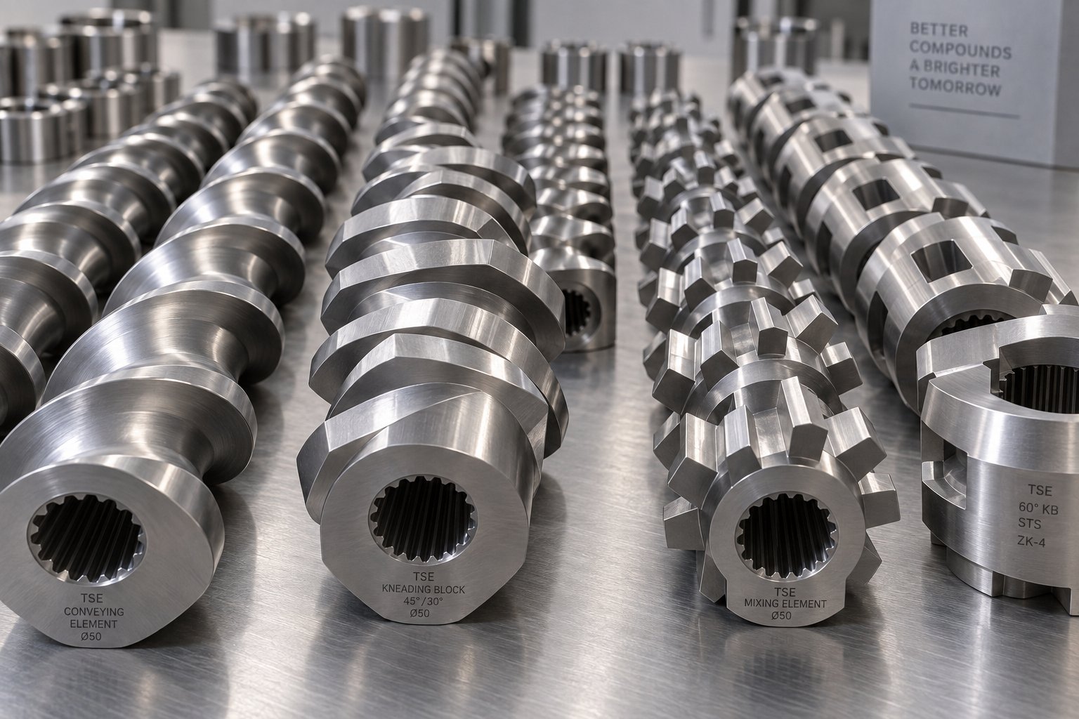
Picture an extruder screw as a sentence. Each individual element is a word, and the order you place them in determines whether the sentence makes sense or falls apart. In a parallel twin screw extruder machine, the screws aren't solid, one-piece shafts. They're assembled from dozens of modular segments, each engineered for a specific job, slid onto a splined shaft in a deliberate sequence. Swap one element, shift its position, or change its stagger angle, and you fundamentally alter how your material behaves from feed throat to die face.
This modular architecture is arguably the single biggest reason co-rotating parallel designs dominate compounding. It's also where most engineers either optimize their process or unknowingly throttle it. Understanding what each element does, and more critically, where to place it, separates a well-tuned screw extruder from one that simply pushes material through a barrel.
Types of Screw Elements and Their Functions
Every element mounted on the shaft belongs to one of a few functional families. Think of them as building blocks, each designed to convey, melt, mix, or restrict material flow. The geometry of each block, its pitch, disk width, stagger angle, and rotation direction, determines how aggressively it works on the polymer melt.
Here's a breakdown of the primary element types you'll encounter when configuring a plastic extruder screw for compounding:
| Element Type | Function | Typical Placement Zone |
|---|---|---|
| Forward Conveying Elements (large pitch) | Rapidly transport solid feedstock into the barrel with minimal shear; high free volume accommodates bulk material | Feed zone (first several barrel sections) |
| Forward Conveying Elements (reduced pitch) | Compress and advance partially melted material; build moderate pressure toward downstream sections | Transition zones between functional sections |
| Narrow Kneading Blocks (forward stagger) | Provide distributive mixing by splitting and recombining melt streams; lower shear intensity than wide blocks | Early mixing zone; gentle blending applications |
| Wide Kneading Blocks (forward stagger) | Deliver strong dispersive mixing; break down agglomerates and filler clusters through high shear stress | Primary melting and intensive mixing zones |
| Neutral Kneading Blocks (90-degree stagger) | Maximize shear and energy input with zero forward conveying; increase local residence time significantly | High-intensity mixing zones where aggressive dispersion is required |
| Reverse Kneading Blocks | Push material backward, creating a melt seal and maximum flow restriction; generate intense shear | Upstream of venting ports; melt seal zones |
| Toothed Mixing Elements (TME) | Promote distributive mixing with low shear; ideal for blending sensitive additives without degradation | Homogenization zones; downstream of intensive mixing |
| Reverse Flight Conveying Elements | Create back-pressure and a melt plug to seal venting zones; shorter length than full-diameter elements to avoid pressure spikes | Immediately upstream of atmospheric or vacuum vent ports |
A few details deserve extra attention. Research from NC State Extension highlights that wider kneading elements promote dispersive mixing, breaking apart clumps through strong shear stress, while narrower kneading elements lean toward distributive mixing, spreading components more evenly without as much particle size reduction. The stagger angle between individual disks in a kneading block further fine-tunes aggressiveness: a 30-degree forward offset conveys gently while mixing, a 60-degree offset balances shear and conveyance, and a 90-degree neutral offset halts forward movement entirely, forcing maximum energy into the melt.
Reverse elements, whether kneading blocks or flight segments, deserve particular respect. They push material backward against the main flow direction, which sounds counterproductive until you realize that this restriction is exactly what creates a filled, pressurized zone upstream. That pressurized zone is essential for effective venting, because without a melt seal, vacuum applied at a vent port would simply suck air backward through unfilled screw channels rather than pulling volatiles out of the polymer.
Building a Screw Configuration for Compounding
Knowing what each element does is only half the puzzle. The sequence in which you arrange them along the shaft, what extrusion engineers call the screw profile or screw configuration, is what transforms a collection of metal parts into a processing strategy.
Imagine walking along the barrel from the feed hopper to the die. Here's how a representative compounding configuration for a screw plastic extruder typically unfolds:
- Feed section (barrels 1-2): Large-pitch forward conveying elements dominate this zone. Their deep channels and high free volume accept bulk pellets or powder from the gravimetric feeder without creating back-pressure. The goal here is simple: move material in, not melt it. Barrel temperatures are usually set low or cooling is applied to prevent premature melting and bridging.
- Melting and first mixing zone (barrels 3-5): Pitch gradually decreases as conveying elements compress material into a tighter channel. Forward kneading blocks then take over, initially with narrow disks for gentle distributive action, transitioning to wider disks that deliver the dispersive shear needed to melt the polymer matrix. Barrel temperatures ramp up through this section. By the end of this zone, the material should be fully molten.
- Side feed incorporation zone (barrel 6-7): If the formulation includes fillers like calcium carbonate, talc, or glass fiber, a side stuffer introduces them here, downstream of the primary melting zone. Forward conveying elements with moderate pitch pull the filler into the melt stream. Introducing abrasive fillers after the polymer is already molten protects the upstream feed section from unnecessary wear.
- Intensive mixing zone (barrels 7-9): A second set of kneading blocks, often wider and with tighter stagger angles, disperses the fillers or additives into the polymer matrix. This is where the heavy lifting of dispersion happens. Neutral or reverse kneading blocks at the end of this section create a melt seal, forcing the screw channels to run fully filled and maximizing mixing intensity.
- Venting zone (barrel 10): Immediately downstream of that melt seal, conveying elements with a large pitch create a partially filled, low-pressure region. A vent port, atmospheric or vacuum, sits above this zone and extracts moisture, trapped air, and volatile compounds. Without the melt seal from the upstream reverse elements, this devolatilization step simply would not work.
- Pressure build-up and metering (barrels 11-12): Reduced-pitch conveying elements or additional distributive mixing elements homogenize the melt one final time, then progressively build the pressure needed to push the compound through the die plate. Consistent pressure here translates directly to stable strand formation and uniform pellet quality.
This layout isn't a rigid recipe. It's a framework. An engineer processing a lightly filled polyolefin blend might simplify the mixing sections and use gentler kneading blocks. A reactive extrusion application might add a second venting section with another set of melt seal elements. The beauty of the modular extruder screw system is that each zone can be independently tuned by swapping, adding, or removing individual elements without fabricating a new shaft.
How Configuration Affects Mixing Intensity and Residence Time
Every element swap you make on the shaft creates a ripple effect across three interconnected variables: shear rate, melt temperature, and residence time distribution. Understanding these relationships is what separates an operator who follows a standard screw layout from an engineer who optimizes one.
Shear rate is controlled primarily by the geometry and aggressiveness of kneading elements. Wider disks with tighter stagger angles generate higher shear, which is essential for breaking apart filler agglomerates or dispersing pigments to sub-micron particle sizes. However, higher shear also converts more mechanical energy into heat. A screw profile loaded with aggressive kneading blocks will produce a hotter melt, which can be beneficial for crystalline polymers that need energy input to melt but destructive for heat-sensitive materials like PVC or certain bioplastics.
Melt temperature is therefore not set solely by the barrel heaters. It's the combined result of barrel temperature setpoints and the viscous dissipation generated by screw element geometry. In many compounding operations, the screw configuration contributes more thermal energy to the melt than the barrel heaters do. This reality makes element selection a thermal management decision as much as a mixing one.
Residence time distribution reflects how long individual material particles spend inside the barrel and how uniformly that time is distributed across the entire flow. Forward conveying elements move material quickly, resulting in short residence times. Neutral and reverse elements slow material down, increasing residence time in their immediate vicinity. A well-designed screw profile for a twin-screw extruder creates a narrow residence time distribution, meaning every particle of material receives approximately the same thermal and mechanical history. A poorly designed profile, one with excessive reverse elements or unbalanced fill levels, produces a wide distribution where some material degrades from overexposure while other material passes through under-mixed.
The practical takeaway is this: screw configuration is the primary lever for controlling product quality in a parallel twin screw extruder. Barrel temperatures, screw speed, and feed rate all matter, but they operate within the processing envelope that the screw profile defines. Change the elements, and you change the boundaries of what's possible.
That processing envelope, however, doesn't depend on element design alone. The physical length of the barrel relative to its diameter, what engineers refer to as the L/D ratio, determines how many functional zones you can fit along the shaft and how much processing work each zone can accomplish.
L/D Ratio and Process Parameter Relationships Explained
You've carefully selected your screw elements and arranged them into a logical processing sequence. But here's a question that trips up even experienced compounders: how do you know whether your barrel is long enough to actually use that configuration effectively? A beautifully designed screw profile crammed into a barrel that's too short will underperform, while an excessively long barrel adds cost and residence time you may not need. The answer lives in one of the most consequential yet frequently misunderstood specifications on any twin screw extrusion machine: the L/D ratio.
Understanding L/D Ratio in Parallel Twin Screw Extruders
L/D ratio is simply the screw's working length divided by its nominal diameter. A machine with 50 mm screws and a barrel length of 2,000 mm has an L/D of 40:1. Sounds straightforward, yet the implications for your twin screw extrusion process are enormous. Every functional zone you read about in the previous section, feed, melting, mixing, venting, pressure build-up, occupies real physical space along the barrel. A longer L/D ratio gives you more room to arrange those zones, more barrel sections for temperature profiling, and more residence time for the polymer to undergo the mechanical and thermal work your formulation demands.
In practice, L/D ratios for parallel twin screw extruders typically range from 20:1 to 48:1, with modern high-performance compounders increasingly pushing to 52:1 and beyond. Where your application falls within that range depends on processing complexity:
- Short L/D ratios (20:1 to 28:1) suit simpler operations like color masterbatch blending or processing thermally sensitive materials that degrade with extended heat exposure. Fewer barrel sections mean shorter residence time, which protects delicate formulations but limits the number of mixing and venting zones you can fit along the shaft.
- Medium L/D ratios (28:1 to 36:1) cover the broadest range of compounding work, including engineering plastics modification, impact modifier incorporation, and standard mineral-filled compounds. This range provides enough barrel length for a full melt zone, one intensive mixing section, and a single venting port, which handles the majority of commercial polymer compounding tasks.
- Long L/D ratios (36:1 to 52:1 and above) become essential when the process demands multiple mixing stages, multiple venting zones, or extended residence time for reactive chemistry. Highly filled compounds requiring downstream filler introduction, devolatilization of moisture-sensitive materials, and in-situ grafting reactions all benefit from the additional processing length. The extra barrel sections also allow more granular temperature zoning, giving operators finer control over melt thermal history.
A common misconception is that longer always means better. It doesn't. Every additional barrel section adds residence time, and excessive residence time degrades heat-sensitive polymers, increases energy consumption, and raises equipment cost. The goal is to match L/D ratio to processing requirements, not to over-specify for safety margin. A well-configured 36:1 extruder system running an optimized screw profile will often outperform a poorly configured 48:1 machine on the same formulation.
How Screw Speed, Feed Rate, Temperature, and Back Pressure Interact
L/D ratio defines the physical playing field. The process parameters you set within that field, screw speed, feed rate, barrel temperature profile, and back pressure, interact in ways that aren't always intuitive. Adjusting one variable almost always shifts the balance of another. Understanding these cause-and-effect relationships is what separates controlled compounding from trial-and-error troubleshooting.
Here are the key interactions every operator of a parallel twin screw extruder machine should internalize:
- Increasing screw speed raises shear energy input and melt temperature. Higher rpm means faster relative motion between screw elements and barrel wall. That motion generates viscous dissipation, the primary heat source in most twin screw extrusion operations. While higher speed can improve mixing intensity, it also pushes melt temperature upward. For shear-sensitive polymers, there's a ceiling beyond which degradation begins.
- Starve-feeding decouples throughput from screw speed. In a starve-fed extruder, a gravimetric feeder controls how much material enters the barrel per unit time, independently of how fast the screws rotate. This is a critical advantage. You can increase screw speed to boost dispersive mixing without simultaneously increasing throughput, or raise throughput at a fixed screw speed by increasing the feed rate. Research on starve-fed extrusion confirms that this feeding mode produces lower pressure development in the initial screw sections and substantially better mixing compared to flood-fed operation, where the screw simply takes as much material as gravity delivers.
- Barrel temperature profiles create distinct functional zones. Setting the feed section cool prevents premature melting and bridging. Ramping temperatures through the melting zone accelerates polymer fusion. Maintaining or slightly reducing temperature in downstream mixing sections allows viscous dissipation from the screw elements to do the work without overheating the melt. Cooling the final barrel sections before the die stabilizes melt viscosity for consistent strand formation. Each zone's temperature setpoint interacts with the local screw element geometry to determine actual melt temperature at that point.
- Back pressure controls fill level and mixing intensity in the barrel. Back pressure originates from two sources: die resistance at the barrel exit, and reverse screw elements or restrictive kneading blocks within the screw profile. Higher back pressure increases the degree of fill in upstream screw channels. A more fully filled channel experiences greater shear and longer residence time, both of which intensify mixing. However, excessive back pressure can cause vent flooding, torque overload, or melt temperature spikes. The interplay between die geometry and screw configuration determines the pressure profile along the entire extrusion extruder.
- Feed rate and screw speed together define specific energy input. Specific energy, measured in kWh/kg, captures how much mechanical work the screws deliver per kilogram of material processed. Raising screw speed at constant feed rate increases specific energy and shear history. Raising feed rate at constant screw speed decreases specific energy and reduces residence time. This ratio is one of the most reliable indicators of process consistency, and it becomes a critical parameter when scaling from laboratory to production equipment.
These interactions don't operate in isolation. Imagine increasing screw speed to improve pigment dispersion in a color compound. The higher shear boosts dispersive mixing, but melt temperature climbs. You compensate by lowering barrel temperature setpoints, which reduces conductive heat input from the barrel wall. The melt temperature stabilizes, but now the melting zone might not fully plasticate the polymer before it reaches the first kneading section. So you adjust the feed rate slightly downward, giving each pellet more time in the melting zone. Every parameter adjustment triggers a chain of secondary effects that must be anticipated and balanced.
Process Parameter Optimization Principles
Given these tightly coupled relationships, how do experienced engineers approach optimization without chasing their tails? A few guiding principles apply across nearly every compounding scenario on a parallel twin screw extruder:
- Start with specific energy as your anchor metric. Before adjusting individual parameters, establish a target specific energy range for your formulation. This value integrates screw speed, feed rate, and motor load into a single number that correlates strongly with mixing quality and melt temperature. Keeping specific energy consistent across batches is one of the most reliable paths to product uniformity.
- Use barrel temperature to support the screw profile, not replace it. Barrel heaters and cooling channels fine-tune melt temperature, but they cannot substitute for proper screw element selection. If you find yourself relying on extreme barrel temperatures to compensate for poor mixing or incomplete melting, the screw configuration itself likely needs adjustment.
- Optimize screw speed and feed rate as a pair, not independently. Changing one without considering the other shifts specific energy and residence time simultaneously. Approach adjustments as ratio changes: if you raise screw speed by 15%, evaluate whether feed rate should track proportionally or remain fixed based on the mixing quality you observe.
- Respect the thermal limits of your polymer. Every resin has a degradation onset temperature. The combination of barrel setpoints and viscous dissipation from screw elements must keep actual melt temperature below that threshold at every point along the barrel, not just at the die exit. Melt temperature probes at multiple barrel locations, rather than a single die measurement, reveal whether hotspots exist inside the process.
- Monitor torque as a real-time process indicator. Motor torque reflects the mechanical resistance the screws encounter. A sudden torque spike can indicate an unmolten solid plug, a feed surge, or excessive back pressure. Gradual torque drift over weeks often signals barrel or screw wear that's reducing processing efficiency before product quality visibly deteriorates.
These principles form a framework, not a recipe. Every formulation, every filler system, and every polymer grade responds differently to parameter changes. The engineers who consistently produce the best compounds aren't the ones who memorize optimal setpoints. They're the ones who understand why each parameter matters and how it connects to everything else in the extruder system.
With the mechanical design and process parameters clearly mapped, the natural next question becomes: where does all this capability actually get applied? The range of materials and industries that depend on parallel twin screw extruders is remarkably broad, and the processing rationale behind each application reveals just how versatile this platform really is.
Industry Applications Where Parallel Twin Screw Extruders Excel
Most technical articles stop at telling you that a parallel twin screw extruder machine handles "plastics, rubber, food, and pharmaceuticals" and then move on. That's about as useful as saying a car "drives on roads." The real question isn't what industries use these machines. It's why each specific application demands the processing characteristics only a co-rotating, self-wiping, modular-screw platform can deliver. When you dig into the material science behind each use case, you'll notice that every application exploits a different combination of the same core advantages: controlled shear, modular flexibility, starve-fed independence, and multi-stage venting capability.
Polymer Compounding and Filled Plastics
Polymer compounding is the heartland of the compounding twin screw extruder. The task sounds simple: blend a base polymer with fillers, reinforcements, or functional additives to create a compound with properties that the neat resin can't achieve on its own. In practice, it's anything but simple. Incorporating 40% calcium carbonate into polypropylene, for example, requires both dispersive mixing to break apart filler agglomerates and distributive mixing to spread those particles evenly throughout the melt. Do one without the other, and you get either visible specks in the finished part or a compound whose mechanical properties vary from pellet to pellet.
The co-rotating parallel design delivers both mixing modes simultaneously. Kneading blocks in the intensive mixing zone generate the high shear stress needed to fracture filler clusters down to primary particle size. Downstream distributive mixing elements then split and recombine the melt stream repeatedly, spreading those particles across the polymer matrix with statistical uniformity. The self-wiping action between screws prevents dead zones where material might stagnate and degrade, a feature that becomes critical when processing engineering polymers like polyamide or PBT at temperatures above 260 degrees Celsius.
For highly filled systems, talc at 30%, glass fiber at 40%, or mineral blends approaching 80%, the downstream side-feeding capability of a polymer extruder is essential. Abrasive fillers introduced at the main feed throat would grind through conveying elements within weeks. Instead, the filler enters through a side stuffer positioned after the polymer is already fully molten, reducing wear in the feed section and ensuring that the filler encounters a liquid matrix rather than unmelted pellets. As industry experts note, co-rotating twin-screw extruders can handle filler loadings up to 80% when configured with appropriate side stuffers and extended barrel lengths.
Masterbatch Production and Color Compounding
Imagine a customer rejects an entire shipment of injection-molded housings because the blue color shifts noticeably between the first and last pellet bags. That nightmare scenario is why masterbatch producers treat pigment dispersion as a science rather than a blending exercise, and why they overwhelmingly rely on co-rotating parallel twin screw extruders to get it right.
Color masterbatch compounding presents a unique challenge: pigment particles often arrive as tightly bound agglomerates that must be broken down to sub-micron primary particles and distributed uniformly within the carrier resin at loading levels that can reach 60% or higher. Inadequate dispersion leaves visible specks. Excessive shear degrades the carrier polymer and shifts the color value. The processing window is narrow, and the consequences of missing it show up immediately in the finished product.
The modular screw architecture of a plastic twin screw extruder gives masterbatch producers the precision they need. By selecting kneading block widths, stagger angles, and placement zones tailored to a specific pigment's particle hardness and agglomerate strength, engineers can dial in exactly the shear intensity required without overshooting. Process engineers at leading compounding equipment manufacturers describe the twin screw extruder as a "toolbox" of unit operations, where each section, from upstream feeding through melting, split feeding, downstream mixing, and devolatilization, can be independently optimized for the pigment and carrier combination at hand.
Split feeding plays a particularly important role. For high pigment loadings, trying to introduce all the color powder at the main feed creates intake problems because of the low bulk density and tendency of fine powders to aerate. Instead, a portion of the pigment enters the main feed with the carrier pellets, while the remaining pigment is introduced through one or more downstream side feeders positioned after the polymer is fully molten. This approach prevents feed throat flooding and ensures each pigment particle contacts a liquid carrier for effective wetting and dispersion.
Reactive Extrusion and Devolatilization
Reactive extrusion pushes the compounding extruder into territory that blurs the line between mechanical processing and chemical engineering. Instead of simply blending ingredients, the extruder becomes a continuous reactor where chemical reactions, grafting, crosslinking, chain extension, or in-situ polymerization, occur inside the barrel while the material is being conveyed and mixed.
Consider maleic anhydride grafting onto polypropylene, a common compatibilizer production process. A peroxide initiator decomposes at elevated temperature, generating free radicals that graft maleic anhydride molecules onto the PP backbone. The reaction needs precise temperature control, thorough mixing to distribute the reactants, and sufficient residence time for the grafting chemistry to proceed to target conversion levels. Too little mixing leaves unreacted maleic anhydride in the product. Too much shear at too high a temperature degrades the PP chain, dropping molecular weight and mechanical properties.
Long L/D ratios of 44:1 to 52:1 are typical for reactive extrusion on a twin screw extruder plastic platform. The extra barrel length accommodates multiple functional zones: an initial melting section, a reaction zone with controlled temperature and residence time, and critically, one or more vacuum devolatilization sections downstream of the reaction zone. Devolatilization removes unreacted monomers, byproduct volatiles, and residual moisture by exposing the melt to reduced pressure through vent ports positioned above partially filled screw channels. Without these venting stages, residual volatiles would cause porosity, odor, or off-gassing in the final product.
The same devolatilization capability serves non-reactive applications as well. PET sheet edge trim recycled directly back into the process needs moisture removal to prevent hydrolytic degradation and IV loss. Undried engineering plastics can be processed on a twin screw extruder equipped with multi-stage vacuum venting, eliminating the separate drying step that single-screw lines require. Each of these applications depends on the parallel extruder's ability to create reliable melt seals using reverse screw elements upstream of every vent port, something the modular element system handles through simple configuration changes.
Recycling and Pelletizing Applications
Plastics recycling is where the versatility of a parallel twin screw extruder machine faces its toughest test. Unlike virgin compounding, where incoming materials arrive in clean, consistent pellet form, recycling feeds are messy. Post-consumer streams contain mixed polymers, residual contaminants, variable moisture levels, and unpredictable melt flow characteristics. Post-industrial streams are cleaner but still present challenges: edge trim from film lines may carry absorbed moisture, production scrap may contain off-spec additives, and regrind particle sizes vary batch to batch.
The co-rotating twin screw extruder addresses these challenges through several mechanisms that single-screw systems cannot easily replicate:
- Multi-stage devolatilization: Vacuum vent ports positioned at multiple barrel locations strip residual moisture, absorbed solvents, and volatile contaminants from the recycled melt. This is especially valuable for post-consumer HDPE and PP streams that retain water from the washing step, a problem that often proves problematic for downstream processing if left unaddressed.
- Dispersion of trace contaminants: Minor-phase polymers that inevitably contaminate a post-consumer feed, small percentages of PET in an HDPE stream, for instance, are dispersed into fine domains by the intense inter-screw mixing. This dispersion prevents large, incompatible inclusions that would create weak points in molded parts.
- Re-compounding with additives and fillers: Recycled feedstock rarely meets performance specifications on its own. A compounding twin screw extruder can simultaneously remove volatiles, incorporate stabilizers to restore weathering resistance, add mineral fillers to boost stiffness, and blend virgin resin to achieve target mechanical properties, all in a single pass. Filler loadings up to 80% have been demonstrated in post-consumer HDPE compounding applications using side stuffers for downstream filler introduction.
- Handling low-bulk-density feedstock: Shredded film, ground fluff from fiber bales, and flaked bottle regrind often have bulk densities too low for gravity feeding. Crammer feeders and high-speed side stuffers push these materials into the barrel, and the starve-fed operation of the twin screw accommodates variable feed rates without surging.
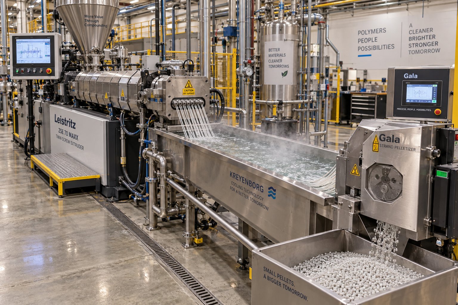
- Consistent pelletization: Whether the downstream system uses strand pelletizing, underwater pelletizing, or water-ring cutting, the uniform melt quality and stable pressure delivery from a well-configured parallel extruder produce pellets with consistent dimensions, low void content, and repeatable bulk density, ready for direct use in injection molding or extrusion processes.
Real-world recycling systems built around co-rotating twin screws span applications from PET and PLA edge trim reclaim for sheet production, where the extruder eliminates the separate drying step, to post-consumer HDPE compounding with high filler loadings, to specialty processes like devulcanization of ground tire rubber. Each system integrates the extruder with upstream metal detection, filtration equipment, and downstream pelletizing as part of a complete reclaim line.
The breadth of these applications reinforces a central theme: the parallel twin screw extruder isn't a single-purpose machine optimized for one material or one industry. It's a configurable processing platform whose modular screw architecture, independent parameter control, and multi-stage barrel design allow it to serve as the backbone of operations as different as automotive compound production and post-consumer waste reclamation. That adaptability is also what makes it the go-to platform for scale-up, where a formulation proven on a small lab machine must eventually deliver the same results at commercial production rates.
Scaling Up from Lab to Production Twin Screw Extruders
You've perfected a formulation on a benchtop twin screw extruder in the lab. The pellets look clean, the dispersion is excellent, and every quality metric hits specification. So you transfer the exact same screw design, temperature profile, and screw speed to a production machine, and everything falls apart. The melt comes out inhomogeneous, pressure fluctuates wildly, and unmelted pellets show up in the discharge. What happened?
This scenario isn't hypothetical. It plays out routinely across the polymer industry because scale-up is one of the most misunderstood steps in twin screw extrusion. The physics of mixing, heat transfer, and shear don't scale linearly with machine size, and engineers who treat scale-up as a simple copy-paste exercise learn that lesson the hard way.
From Lab-Scale to Pilot-Scale to Production
The development pathway for any compounding process typically moves through three stages, each served by a different class of laboratory twin screw extruder or production machine. A lab scale twin screw extruder with 12 to 27 mm screw diameters handles formulation screening and early-stage development. These small machines consume minimal raw material, often just a few kilograms per hour, making them ideal for iterating through dozens of additive ratios or filler loadings without burning through expensive resins. Pilot-scale units in the 35 to 50 mm range then validate whether a promising lab formulation can run continuously at higher rates. Production-scale machines, spanning 50 to 135 mm and beyond, deliver the commercial throughput that justifies the entire development effort.
The underlying assumption connecting these scales is geometric similarity: the target machine's screw proportions, including the outer-diameter-to-inner-diameter ratio and the L/D ratio, match those of the reference machine. A case study published by Plastics Technology demonstrated this principle using co-rotating, fully intermeshing parallel extruders at 26 mm, 40 mm, and 92 mm, all sharing an L/D of 44 and an OD/ID ratio of 1.55. Geometric similarity ensures that the fundamental flow patterns inside the barrel remain comparable across sizes, even though absolute dimensions change.
The most reliable metric for bridging scales is specific mechanical energy (SME), measured in kWh/kg. SME captures how much energy the drive motor transfers through the screws into each kilogram of compound. In that same case study, the optimized lab-scale process on the 26 mm machine produced a target SME of 0.083 kWh/kg. Whenever the larger machines matched that SME value, the process ran stably and product quality held. Whenever SME deviated significantly, problems surfaced immediately, from phase separation to unmelted solids discharging through the die.
Two classical scaling laws govern how throughput increases with screw diameter. As extrusion engineers describe it, the cubic law (Q proportional to D cubed) applies when the process is limited by volumetric capacity, yielding the maximum throughput gain. The square law (Q proportional to D squared) applies when heat transfer through the barrel wall is the bottleneck, producing a more conservative throughput increase. Real-world scale-up almost always lands somewhere between these two extremes, and the engineer's job is to figure out where.
What Transfers and What Changes During Scale-Up
Here's the critical reality: identical process settings on a lab scale extruder and a production machine do not produce identical results. Screw speed, barrel temperature profiles, and even screw configuration often require adjustment at each scale because the physics of heat transfer and shear change with machine size.
| Dimension | Lab Scale (12-27 mm) | Pilot Scale (35-50 mm) | Production Scale (50-135+ mm) |
|---|---|---|---|
| Screw Diameter Range | 12-27 mm | 35-50 mm | 50-135+ mm |
| Typical Throughput Range | 0.5-20 kg/h | 20-200 kg/h | 200-5,000+ kg/h |
| Primary Purpose | Formulation screening, additive optimization, feasibility testing | Process validation, parameter refinement, sample production | Commercial manufacturing, continuous production |
| Surface-to-Volume Ratio | High (efficient barrel heat transfer) | Moderate | Low (reduced barrel influence on melt temperature) |
| Heat Transfer Effectiveness | Excellent; barrel temperature strongly influences melt | Good; some divergence from barrel setpoints | Limited; viscous dissipation dominates thermal profile |
| Key Scale-Up Consideration | Establish target SME and baseline quality metrics | Validate screw configuration; adjust temperatures and speed for SME match | Expect screw redesign; compensate for reduced heat transfer and altered fill behavior |
The surface-to-volume ratio is the root cause of most scale-up headaches. A laboratory extruder has a large barrel surface area relative to the small volume of polymer inside. Barrel heaters and cooling channels exert strong control over melt temperature. Scale up to a 92 mm production machine, and the internal volume has grown with the cube of the diameter while the barrel surface area has grown only with the square. The barrel's thermal influence weakens dramatically, meaning that viscous dissipation from the screw elements becomes the dominant heat source.
This shift explains a counterintuitive finding from the Dow case study: transferring identical operating conditions from the 26 mm lab machine to the 92 mm production extruder produced an SME of only 0.026 kWh/kg, a 69% drop. The screws simply could not transfer enough energy into the compound. Root cause analysis revealed that a low-viscosity raw material created a lubricating effect along the larger barrel and screw surfaces, a phenomenon that didn't appear at lab scale. Resolving it required changes to screw design, cooler barrel temperatures, and modified feeding strategy, ultimately bringing SME back to 0.086 kWh/kg and restoring full product quality.
Residence time distribution also shifts during scale-up. Larger free volumes and different fill levels mean that material spends more or less time in specific barrel zones compared to the reference machine. Engineers should expect to iterate on screw configuration and operating parameters at each new scale, treating the lab result as a target rather than a template.
Practical Scale-Up Principles
Given these challenges, how do experienced process developers approach scale-up without reinventing the process at every step? These guiding principles, drawn from both published case studies and established extrusion theory, provide a reliable framework:
- Maintain similar specific mechanical energy (SME). SME is the single most transferable metric across scales. If your lab process achieves 0.08 kWh/kg and product quality meets specification, target that same value on the pilot and production machines. Deviations beyond 10-15% typically signal that process adjustments are needed.
- Preserve screw configuration ratios, not absolute element counts. A kneading block section that occupies 15% of the barrel length on the lab machine should occupy approximately the same proportion on the production machine. Absolute element lengths scale with diameter, but functional zone proportions should remain consistent.
- Account for declining heat transfer efficiency at larger diameters. Barrel temperature setpoints that work perfectly on a 26 mm laboratory twin screw extruder may need to be lowered on a 92 mm machine because the reduced surface-to-volume ratio means less heat can be removed through the barrel wall. Plan for more aggressive screw-based mixing to compensate for the loss of barrel-driven thermal input.
- Use pilot-scale trials as a diagnostic bridge. Jumping directly from a 15 mm lab unit to a 100 mm production machine skips the scale where most process limitations first reveal themselves. Pilot-scale runs on a 40 to 50 mm machine expose heat transfer boundary conditions, feed behavior anomalies, and screw design weaknesses before they become costly production failures.
- Plan for process validation at each scale. Expect to adjust screw speed, barrel temperature profiles, and possibly screw element arrangement at every transition. Scale-up is an iterative design process, not a one-shot calculation. Track SME, melt temperature, torque percentage, and die pressure as your validation metrics across all three scales.
- Consider the square-law and cubic-law boundaries for throughput estimation. Use the cubic law (Q proportional to D cubed) as the upper throughput target when no heat transfer limitations exist. If melt temperature runs high or quality drifts, pull back toward the square law (Q proportional to D squared) to stay within the thermal management envelope of the larger machine.
Scale-up is where the elegance of twin screw extrusion theory collides with the messiness of real-world materials, equipment tolerances, and production economics. The engineers who navigate it successfully are the ones who treat each scale transition as a process development step in its own right, using SME as their compass and screw configuration as their primary adjustment tool.
Yet even a perfectly scaled process doesn't run indefinitely without attention. The screws and barrels that deliver precise mixing and conveying at startup are slowly transformed by every kilogram of abrasive filler, every hour of high-shear operation, and every reactive formulation that passes through them. Knowing where wear strikes first, and what to do about it, determines whether your production machine holds its optimized performance for months or drifts off-spec within weeks.
Maintenance and Wear Management for Long Twin-Screw Extruder Machine Life
That gradual drift is rarely dramatic. You won't hear an alarm go off the moment your twin screw and barrel system starts losing its edge. Instead, you'll notice subtle signs: a slight uptick in melt temperature at the same screw speed, a pellet color consistency that was once rock-solid now drifting batch to batch, or a torque reading that creeps higher to maintain the same throughput. These signals are easy to dismiss as normal process variation, but they almost always trace back to the same root cause: physical wear inside the barrel and on the screw elements themselves.
Understanding where wear happens, why it accelerates, and what you can do to manage it is one of the most practical skills a compounder can develop. It's also one of the least discussed. Most training focuses on screw configuration and parameter optimization, treating the hardware as a constant. In reality, every kilogram of compound that passes through your twin-screw extruder machine reshapes the metal surfaces that define your process.
Common Wear Patterns in Screws and Barrels
Wear inside a parallel twin screw extruder doesn't happen uniformly. It concentrates in specific zones and takes distinct forms depending on what the machine is processing. Recognizing each pattern early, before it cascades into quality problems, is the first step toward effective wear management.
Abrasive wear is the most prevalent form in compounding operations. It results from hard particles, calcium carbonate, glass fiber, talc, titanium dioxide, grinding against the screw flight tips, barrel bore surfaces, and kneading element edges. The sharp, machined corners of new screw elements gradually become rounded, smooth, and occasionally polished as material erodes the metal surface. You'll typically see the worst abrasive damage in two areas: the feed zone where solid filler particles first contact the screws, and the filler incorporation zone downstream of a side stuffer where hard additives enter the melt at high concentration. The severity scales directly with filler hardness, loading level, throughput, and screw speed.
Adhesive wear is a different mechanism entirely. It occurs when metal surfaces rub directly against each other, and it's most common in high-shear kneading zones where deflection of the screw shafts allows flight tips to contact the barrel wall or the opposing screw. The telltale signs are score marks on the barrel bore and flattened outer diameters on screw flights. Twin screw extruders are rigidly supported at the gearbox end, but the screws rely on the molten polymer itself for support along the rest of the barrel length. When a machine idles between production runs with screws spinning at moderate speed but no material providing that support, adhesive wear accelerates rapidly. This is one reason experienced operators always reduce screw speed to a crawl during transitions and shutdowns.
Corrosive wear appears as pitting or dimpling on metal surfaces and results from chemical attack by reactive formulations, acidic off-gases, or even condensation on cooled barrel sections. Processing flame-retardant compounds, halogenated additives, or reactive chemistries that release acidic byproducts can erode conventional steel surfaces from the inside out, even if the mechanical loading is relatively gentle.
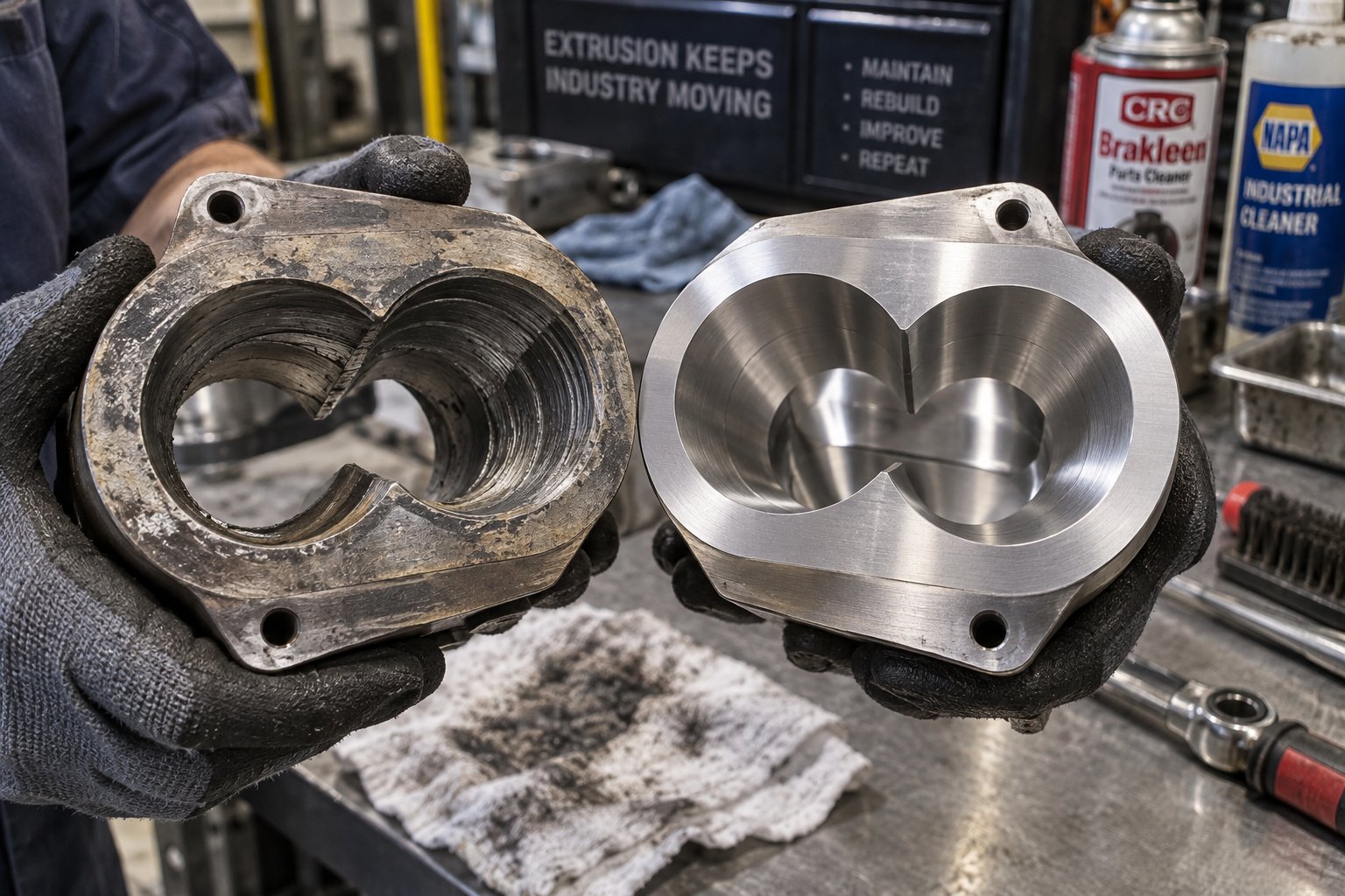
Here's the part that catches many engineers off guard: worn twin screw and barrel components don't just reduce throughput. They fundamentally alter your process. As the clearance between screw flight tips and the barrel bore increases, melt leaks backward over the flights instead of being positively conveyed forward. This back-leakage reduces effective pumping, increases local residence time, and raises melt temperature variability. Worn kneading blocks lose their tight intermeshing geometry, which degrades both dispersive and distributive mixing. The compound that came off the machine at 98% dispersion quality six months ago might now test at 90% with no parameter changes whatsoever. The screws are simply no longer doing the same work.
Preventive Maintenance Best Practices
Waiting until product quality visibly deteriorates before inspecting your twin-screw extruders is the most expensive maintenance strategy there is. By that point, wear has already progressed far enough to affect output, and often far enough to damage adjacent components that would have been fine with earlier intervention. A structured preventive protocol catches problems while they're still minor and keeps your machine inside its optimized processing window.
- Monitor torque and motor load continuously. Torque trending is your earliest warning system. A gradual upward drift at constant screw speed and feed rate suggests increased drag from worn or misaligned components. A sudden spike points to feed blockages, unmolten solids, or a foreign object entering the barrel. Log these values daily and look for week-over-week trends.
- Perform periodic screw pulls and visual inspections. Remove the screws at regular intervals, typically monthly for high-abrasion formulations and quarterly for standard compounding, and inspect each element individually. Look for rounded flight tips on conveying elements, smoothed edges on kneading blocks, and score marks that indicate metal-to-metal contact. Industry guidelines suggest replacing screw elements when outer diameter has decreased by approximately 5% over three-quarters of the element length.
- Measure barrel bore diameter at regular intervals. Use bore gauges or micrometer probes to check for diameter increases along the barrel length. A bore that has enlarged by roughly 5% over a length of one screw diameter is approaching replacement threshold. Focus measurements on high-wear zones: feed sections processing abrasive fillers and intensive mixing sections where kneading blocks operate.
- Check screw shaft alignment and spline condition. Worn splines allow screw elements to wobble on the shaft, creating non-concentric rotation that accelerates barrel contact wear. Inspect spline profiles during every screw pull and replace shafts showing visible wear or deformation.
- Analyze gearbox oil on a scheduled basis. Oil analysis detects metal particles from bearing wear, contamination from seal leaks, and lubricant degradation long before any of these issues cause a catastrophic gearbox failure. Quarterly sampling is standard practice; increase frequency for machines running 24/7.
- Service heating and cooling systems proactively. Clogged cooling channels reduce barrel temperature control precision, forcing the process to drift. Burned-out heater bands create cold spots that alter local melt viscosity. Inspect all heating elements and flush cooling circuits at least twice per year, more often in hard-water environments where scale buildup is aggressive.
- Calibrate temperature and pressure sensors regularly. A sensor reading 10 degrees Celsius low masks a melt temperature that's actually 10 degrees above your intended setpoint. That hidden overshoot degrades polymer, shifts product properties, and misleads your troubleshooting efforts. Annual calibration of all barrel thermocouples and pressure transducers keeps your data trustworthy.
Sounds like a lot of work? Consider the alternative. Unplanned downtime for an emergency screw replacement on a production-scale parallel twin screw extruder can cost days of lost output and thousands in rush-order component fees. A structured preventive schedule spreads that effort across manageable increments and almost always costs less than a single catastrophic failure.
Extending Barrel and Screw Service Life
Preventive maintenance catches wear early. But the real leverage for extending service life comes from specifying the right materials and engineering solutions for your specific processing demands before wear becomes a problem.
The metallurgy of your barrel liner and screw element surfaces directly determines how long they'll resist the abrasion, adhesion, and corrosion they face every production hour. Common material strategies include:
- Nitrided steel: Gas nitriding hardens the surface layer of tool steel to approximately HV 900-1000, creating a wear-resistant case that works well for standard polymer compounding with low to moderate filler loadings. It's the most cost-effective treatment for general-purpose twin-screw extruders and provides good protection against adhesive wear in kneading zones.
- Bimetallic liners: For barrels processing highly abrasive formulations, bimetallic construction bonds a wear-resistant alloy, typically nickel-based or iron-based with carbide reinforcement, to the inner bore surface. Bimetallic barrels can exceed five years of continuous service under demanding PVC, WPC, or high-filler compounding conditions where nitrided barrels might last only two to three years. The upfront investment is higher, but the reduced replacement frequency and extended uptime typically deliver lower total cost of ownership.
- Carbide-based coatings and solid carbide inserts: The most aggressive wear environments, processing glass fiber at 40% or higher, running abrasive recycled feedstock with contaminants, or handling corrosive reactive chemistries, demand the hardest available surfaces. HVOF (high-velocity oxygen fuel) tungsten carbide coatings achieve surface hardness in the range of 58-62 HRC and resist both abrasion and chemical attack. Solid carbide barrel segments offer the longest dimensional stability for extreme-duty applications.
The critical insight is that no single metallurgy solution fits every application. A barrel designed for virgin polyolefin blending would be massively over-engineered with solid carbide inserts, wasting money without meaningful benefit. Conversely, a standard nitrided barrel running 60% glass-fiber-reinforced nylon will wear out in a fraction of its expected life, costing far more in unplanned replacements and quality drift than a properly specified bimetallic or carbide-lined alternative would have.
This is where application-matched barrel engineering makes a measurable difference. Suppliers who design custom parallel twin screw barrels around the specific materials, filler loadings, and production intensities their customers face can match liner metallurgy, bore tolerances, and thermal management features to the actual wear profile of the process. NANHAIYA, for instance, supports compounding, recycling, pelletizing, granulation, and masterbatch producers with parallel twin screw barrel solutions engineered for the exact demands of each application, whether that means bimetallic liners for highly filled recycling streams or precision-finished bores for tight-tolerance masterbatch production.
Investing in the right barrel and screw metallurgy isn't a luxury. It's a direct input to process stability, product quality, and cost per kilogram produced. A barrel that holds its dimensional tolerances for years rather than months means your carefully optimized screw configuration continues to deliver the mixing, conveying, and devolatilization performance it was designed for, without the gradual drift that sends operators chasing phantom process problems.
Of course, even the best-maintained and best-engineered hardware encounters processing issues from time to time. When output surges, vent ports flood, or dispersion quality drops despite no obvious wear, the problem usually lives in the interaction between screw configuration, process parameters, and material behavior rather than in the metal itself. Knowing how to systematically diagnose those issues is the difference between hours of downtime and a quick corrective adjustment.
Troubleshooting Common Parallel Twin Screw Extruder Issues
Something has changed. Output that ran steady for weeks now surges every few minutes. Or your vent port, which never caused trouble before, suddenly floods with molten polymer. Maybe dispersion quality has drifted just enough to trigger customer complaints, even though nobody touched the operating setpoints. These scenarios are frustrating precisely because they seem to appear without an obvious cause.
Troubleshooting a twin screw plastic extruder isn't about guessing. It's about following a structured diagnostic path that narrows the possibilities quickly and points you toward the right corrective action, whether that means swapping a few screw elements or replacing a worn barrel section. The modular architecture that makes parallel twin screw extruders so versatile in processing also makes them uniquely diagnosable, because you can isolate and address problems zone by zone rather than treating the machine as a black box.
Diagnosing Common Processing Problems
Most issues that arise during compounding operations fall into a handful of recognizable symptom categories. The table below maps each symptom to its most likely causes and the corrective actions that experienced operators reach for first. Think of it as your starting checklist before diving deeper into root cause analysis.
| Symptom | Likely Causes | Corrective Actions |
|---|---|---|
| Output surging or inconsistent throughput | Feeder speed fluctuations; bridging or accumulation in feed hopper; worn conveying elements reducing forward pumping; inconsistent raw material bulk density | Verify gravimetric feeder calibration and screw speed stability; check hopper for material bridging or buildup; inspect feed-zone conveying elements for worn flight tips; evaluate incoming material lot consistency |
| Insufficient mixing or poor dispersion | Kneading block configuration too mild for the formulation; screw speed too low relative to feed rate; worn kneading elements with rounded edges and increased clearances; filler introduced too far downstream with insufficient mixing length remaining | Add wider kneading blocks or tighter stagger angles in mixing zones; increase screw speed to raise specific energy input; replace worn kneading elements; relocate side feeder position upstream to provide more mixing residence |
| Excessive melt temperature | Overly aggressive screw configuration generating excess viscous dissipation; screw speed too high for current feed rate; barrel cooling channels clogged or cooling valves malfunctioning; degraded or incorrect barrel temperature PID tuning | Replace aggressive neutral or reverse kneading blocks with gentler forward-stagger elements; reduce screw speed or increase feed rate to lower specific energy; flush cooling circuits and verify solenoid valve operation; retune barrel temperature PID parameters |
| Vent flow or vent flooding | Inadequate melt seal upstream of vent port; excessive fill level in vent zone due to high back pressure from die or downstream restriction; worn reverse elements failing to create sufficient seal; barrel temperature too low in vent zone causing high melt viscosity | Add or lengthen reverse elements upstream of vent port to strengthen melt seal; reduce die restriction or open screen pack; replace worn reverse flight or reverse kneading elements; raise barrel temperature in vent zone to reduce viscosity and improve volatile release |
| Torque overload or motor tripping | Feed rate exceeding machine capacity at current screw speed; unmolten solids reaching kneading zone due to insufficient melting; powder accumulation avalanching into barrel; foreign object or metal contamination in feed | Reduce feed rate or increase screw speed to lower fill level; raise barrel temperatures in melting zone; install hopper agitator or vibrator to prevent powder bridging and avalanche events; verify upstream metal detection and screening systems |
| Die pressure fluctuations | Inconsistent feeder output; variable melt viscosity from uneven temperature profile; worn metering-zone elements allowing pressure pulsation; partially blocked screen pack or die holes | Audit feeder performance and recalibrate if deviation exceeds ±1-2%; check all barrel zone temperatures for deviation from setpoints; inspect metering section elements for wear; clean or replace screen pack and inspect die plate for partial blockages |
Notice a pattern? Many symptoms share overlapping root causes. Feeder inconsistency, for instance, shows up as output surging, torque spikes, and die pressure fluctuation simultaneously. That overlap is exactly why a systematic approach matters more than chasing individual symptoms in isolation.
Root Cause Analysis Approach
When a problem surfaces on any extruder machine for plastic compounding, resist the urge to immediately adjust screw speed or barrel temperatures. Instead, work through a diagnostic sequence that eliminates possibilities in logical order, starting with the easiest checks and moving toward the most involved inspections. Experienced compounding engineers recommend first determining whether the problem is chronic, meaning it appears every time a particular formulation runs, or transient, meaning a previously stable process has suddenly changed behavior. Chronic issues point to fundamental process design problems like an unsuitable screw configuration or incorrect operating parameters. Transient issues point to something that has changed recently: a new raw material lot, a worn component, an environmental shift, or an operator error.
With that distinction in mind, follow this diagnostic sequence:
- Check feed system consistency first. Verify that each gravimetric feeder is delivering its target rate within ±1-2% variation. Inspect hoppers for bridging, rat-holing, or powder accumulation that could cause intermittent avalanches into the barrel. A surprising number of "extruder problems" actually originate upstream of the feed throat.
- Evaluate screw configuration suitability. Ask whether the current element arrangement matches the formulation being processed. A screw profile optimized for a 20% talc-filled compound may be far too mild for a 50% calcium carbonate formulation, or far too aggressive for an unfilled polymer blend. If the problem is chronic across every batch, the screw design itself is the most likely culprit.
- Review barrel temperature profiles for deviation. Compare actual zone temperatures to setpoints. Look for zones that consistently overshoot or undershoot, which may indicate failed heater bands, stuck cooling valves, or fouled cooling channels. A barrel temperature tolerance of ±5 degrees Celsius is generally acceptable; deviations beyond that warrant immediate investigation of the heating and cooling hardware.
- Inspect screw elements and barrel bore for wear. Pull the screws and examine each element visually. Rounded flight tips, polished kneading block edges, and score marks on barrel surfaces all indicate dimensional changes that directly degrade mixing and conveying performance. Measure critical dimensions against original specifications.
- Verify process parameter setpoints against validated ranges. Confirm that screw speed, feed rate, vacuum level, and die temperature all fall within the operating window established during process validation. Operator adjustments that drift outside validated ranges are a common source of transient quality problems, especially across shift changes.
This sequence works because it moves from the simplest, fastest checks toward the more time-consuming inspections. A feeder recalibration takes minutes. A full screw pull takes hours. Starting with the feed system and parameter verification eliminates the most common causes before you invest the downtime required for a physical hardware inspection.
One additional diagnostic tool deserves mention: trend data. Most modern twin extruder control systems log process parameters continuously. Reviewing torque, die pressure, and melt temperature trends over hours, days, or weeks reveals patterns, such as gradual drifts, periodic oscillations, or sudden shifts, that point directly toward specific root causes. A gradual upward trend in torque over months, for example, strongly suggests progressive screw or barrel wear. A sudden shift in die pressure that coincides with a raw material lot change points toward incoming material variability. These temporal patterns are invisible when you only look at instantaneous numerical readouts on the control screen.
When to Reconfigure vs. When to Replace Components
Here's the practical question every operator of a parallel twin screw extruder machine eventually faces: is this problem fixable by rearranging screw elements and adjusting parameters, or does it require replacing physical hardware?
The answer usually depends on whether the issue stems from a design mismatch or a dimensional change.
Reconfigure when the problem is chronic and traceable to the screw profile or process settings. Insufficient mixing on a new formulation, excessive melt temperature from an overly aggressive kneading section, or vent flooding caused by a weak melt seal are all solvable by swapping individual elements. This is where the modular design of co-rotating screw extruders delivers its greatest practical benefit: you can pull the screws, replace a few kneading blocks with wider or narrower alternatives, add a reverse element upstream of the vent, or extend the conveying section in the feed zone, all without fabricating a new shaft or purchasing a new machine. Parameter adjustments, such as shifting screw speed, modifying barrel temperature profiles, or changing the feed rate ratio, are the first line of defense for transient issues related to material lot variability or environmental changes.
Replace components when inspection reveals that wear has changed the physical dimensions of the hardware beyond acceptable tolerances. Barrel bores that have enlarged enough to create excessive clearance between flight tips and the bore wall cannot be restored by changing screw elements. Kneading blocks with rounded, polished edges that no longer deliver the designed shear intensity need to be replaced with new elements. Failed heating zones with burned-out bands or cracked cartridge heaters require hardware replacement, not parameter workarounds. Trying to compensate for worn hardware by pushing parameters harder, running faster to maintain throughput or raising barrel temperatures to offset reduced shear, often accelerates the wear and creates secondary problems like thermal degradation or torque overload.
The modularity of parallel twin screw extruders makes the replacement decision less painful than it would be on a monolithic screw design. You don't scrap an entire screw shaft because three kneading blocks in the mixing zone are worn. You replace those three elements and return the machine to service. Keeping a documented inventory of critical spare elements, especially the high-wear kneading blocks and conveying elements in filler incorporation zones, cuts unplanned downtime from days to hours.
Effective troubleshooting, then, isn't just about fixing what's broken today. It's about building the diagnostic habits and spare-parts strategy that prevent small problems from compounding into costly production failures. The engineers who do this well treat every process deviation as information, a data point that refines their understanding of how their specific machine, formulation, and operating conditions interact. That knowledge, built over dozens of production campaigns, becomes the foundation for making smarter equipment decisions the next time a new line or capacity expansion comes up for evaluation.

How to Choose the Right Parallel Twin Screw Extruder Machine
Diagnosing and resolving processing issues is a skill built through experience, but there's a way to avoid many of those headaches entirely: choosing the right machine in the first place. Most engineers invest weeks evaluating screw configurations and optimizing process parameters on equipment that was never properly matched to their application. The selection stage is where long-term processing consistency, cost efficiency, and operational flexibility are either built in or permanently compromised.
With so many twin screw extruders for sale across global markets, it's tempting to shortlist machines purely on headline specifications and extruder machine price. That approach almost always leads to compromises that surface months after installation. A more effective strategy starts with your application and works backward to the machine.
Key Selection Criteria for Your Application
Before requesting a single quote, define the processing demands your machine must meet. Every specification you evaluate later should trace back to these foundational requirements:
- Application type: Are you compounding filled polymers, producing color masterbatch, running reactive extrusion, recycling post-consumer streams, or doing some combination? Each application imposes different demands on mixing intensity, venting capability, and screw element variety.
- Material properties: Consider the viscosity range, thermal sensitivity, and abrasiveness of your formulations. Processing 40% glass-fiber-reinforced nylon creates entirely different wear and torque demands than blending unfilled polyolefins.
- Required throughput range: Define both your current production target and realistic future growth. A machine sized only for today's volumes may bottleneck within two years of a successful product launch.
- L/D ratio needs: Simple blending operations may work well at 36:1. Multi-stage devolatilization, reactive chemistries, or heavily filled systems typically require 44:1 to 52:1 or longer.
- Torque density requirements: High-torque gearboxes rated at 10-12 Nm/cm3 are essential for stiff engineering polymers and high-filler compounds. Under-specifying torque leads to frequent overload trips that disrupt production and risk material degradation inside the barrel.
- Screw diameter selection: Diameter determines throughput ceiling. Larger screws handle higher volumes but require proportionally more powerful drives. Match diameter to your volume requirements rather than defaulting to the largest available option.
Documenting these criteria before engaging any twin-screw extruder manufacturer prevents the common trap of evaluating machines against each other rather than against your actual processing needs.
Evaluating Machine Specifications and Manufacturer Support
Spec sheets tell you what a machine is. They rarely tell you how well it will perform with your material. When you're comparing a plastic extruder machine for sale from one supplier against another, look beyond the headline numbers and probe the engineering decisions behind them.
Gearbox torque rating relative to screw diameter is your first checkpoint. A high torque density ensures the machine handles worst-case processing scenarios, such as a sudden viscosity spike from a cold-start condition or a feeder surge, without stalling. Ask suppliers to express torque in Nm/cm3 of displacement volume so you can make fair cross-platform comparisons.
Barrel metallurgy options matter more than most buyers realize. A supplier offering only standard nitrided barrels limits your ability to process abrasive or corrosive formulations without accelerated wear. Look for availability of bimetallic liners, carbide-based coatings, and corrosion-resistant alloys matched to your specific materials. This is where your supply chain flexibility becomes critical. Specialized component manufacturers who engineer barrels for specific processing demands, rather than offering one-size-fits-all solutions, deliver measurably longer service life and tighter dimensional stability. NANHAIYA's custom parallel twin screw barrel solutions, for example, support compounding, recycling, pelletizing, granulation, and masterbatch producers with barrel metallurgy and bore specifications tailored to each application's unique wear profile.
Heating and cooling zone granularity determines how precisely you can shape the thermal profile along the barrel. Machines with eight to twelve independently controlled zones provide far finer temperature management than those with five or six, a difference that becomes critical for heat-sensitive polymers and reactive formulations.
Screw element library breadth defines your future flexibility. A supplier with a comprehensive range of conveying pitches, kneading block angles, distributive mixing elements, and reverse configurations gives you room to optimize for new formulations without purchasing custom-machined parts. Ask how many distinct element geometries are available and whether the supplier maintains stock for rapid delivery.
Beyond hardware, evaluate the depth of application support. Can the supplier run trials with your actual materials on a comparable machine before purchase? Do they provide screw configuration recommendations based on your formulation, or hand you a generic layout? The difference between these two approaches often determines whether your machine hits target quality on the first production run or requires months of optimization.
When assessing the overall plastic extrusion machine cost, factor in the total cost of ownership discussed earlier in this article: energy consumption, spare parts pricing and lead times, barrel and screw replacement frequency, and the availability of factory-direct component suppliers who can deliver compatible replacements without OEM markup. A machine with a higher purchase price but lower lifecycle cost almost always outperforms a budget alternative over a ten-year horizon. Evaluating an extruder machine for sale purely on acquisition cost is the single most common procurement mistake in this industry.
Making a Confident Investment Decision
The best parallel twin screw extruder machine is one whose screw and barrel system, process control capability, and manufacturer support are precisely matched to your specific material requirements and production goals.
That principle sounds simple, but applying it requires the discipline to resist two common temptations: over-specifying for imaginary future needs that inflate capital cost, and under-specifying to hit a budget target that creates operational limitations within the first year.
The plastic extruder machine price you pay on day one is a fixed, one-time event. The quality of your screws and barrels, the precision of your temperature control, and the responsiveness of your component supply chain determine what you pay every day after that, in energy, maintenance, downtime, and product consistency. Engineers who internalize this distinction make purchasing decisions that hold up for a decade or more. Those who don't find themselves back in the market far sooner than planned, searching through twin screw extruder for sale listings for a replacement that should have been specified correctly the first time.
Barrel and screw quality isn't a line item to optimize on price. It's the foundation that every other process decision rests on. Choose it deliberately, match it to your application, and your parallel twin screw extruder will deliver the processing performance, product quality, and cost efficiency that justified the investment in the first place.
Frequently Asked Questions About Parallel Twin Screw Extruder Machines
1. What is the difference between a parallel and conical twin screw extruder?
A parallel twin screw extruder uses two equal-diameter screws inside cylindrical bores, while a conical twin screw extruder features tapered screws that converge from a wide feed end to a narrow discharge. Parallel designs offer modular screw elements, higher screw speeds (up to 1,200 rpm), greater throughput, and wider processing flexibility for compounding, masterbatch, and recycling. Conical extruders suit low-speed, high-compression tasks like rigid PVC profile and pipe extrusion. Parallel screws also tend to last roughly twice as long under comparable conditions, and their segmented design allows individual worn elements to be replaced without scrapping the entire shaft.
2. How do you choose the right L/D ratio for a parallel twin screw extruder?
L/D ratio selection depends on processing complexity. Short ratios (20:1 to 28:1) work for simple blending or thermally sensitive materials needing minimal residence time. Medium ratios (28:1 to 36:1) handle standard compounding tasks including mineral-filled compounds and engineering plastics. Long ratios (36:1 to 52:1+) are necessary for multi-stage devolatilization, reactive extrusion, and heavily filled systems requiring multiple mixing and venting zones. The goal is to match L/D to your specific formulation demands rather than defaulting to the longest available option, since excess barrel length adds unnecessary residence time and energy cost.
3. What causes wear in twin screw extruder barrels and screws, and how can it be reduced?
平行双螺杆挤出机主要受三种磨损机制的影响。磨粒磨损是由于玻璃纤维、碳酸钙和滑石粉等硬质填料与金属表面摩擦造成的,这种磨损主要集中在进料区和填料掺入区。粘着磨损是由于螺杆轴挠曲导致螺杆叶片与机筒内壁接触造成的,尤其是在空转无料时。腐蚀磨损则是由活性配方或酸性副产物的化学侵蚀引起的。减少磨损的方法包括:选择与应用相匹配的机筒金属材料,例如双金属衬里或碳化物涂层;通过侧填料器在熔融区下游引入磨粒填料;以及在过渡过程中保持合适的螺杆转速。像南海亚这样的供应商可以根据每种应用的具体磨损情况,定制带有衬里材料的平行双螺杆机筒。
4. 如何将双螺杆挤出工艺从实验室规模扩大到生产规模?
成功的规模化生产依赖于在不同尺寸的机器中保持相似的比机械能(SME,单位为kWh/kg),而不是复制相同的运行参数。实验室规模的机器(12-27毫米)用于确定目标SME和基准质量。中试规模的机器(35-50毫米)用于在更接近生产条件下验证工艺。生产规模的机器(50-135毫米以上)需要进行调整,因为表面积与体积之比显著下降,导致筒体传热的影响减弱,粘性耗散成为主要的热输入。应保持螺杆配置区域的比例,而不是绝对的元件数量;预计在每个规模下都需要迭代调整筒体温度和螺杆转速;并使用立方定律和平方定律作为处理量的上限和下限。
5. 平行双螺杆挤出机最适合用于哪些应用?
平行双螺杆挤出机在需要高产量、深度混合和配方灵活性的应用中表现卓越。其主要应用包括:添加矿物填料或玻璃纤维增强材料(添加量高达 80%)的聚合物混炼;需要亚微米级颜料分散的色母粒生产;用于接枝和链延伸反应的反应挤出;对水分敏感的工程塑料的脱挥发分处理;以及消费后塑料回收利用(其中污染物去除和重新混炼可在一次操作中完成)。其模块化螺杆结构允许一台机器重新配置以适应这些不同的任务,使其成为任何需要处理多种聚合物或配方的行业的标准平台。
Written by
Nanhaiya Technical Team
Zhoushan Nanhaiya Plastic Machinery Co., Ltd.
The Nanhaiya technical team supports screw and barrel manufacturing projects through application review, technical communication, custom manufacturing coordination, and production and quality control.
Discuss Your Application
Related Articles
More insights on screw barrel technology and plastics processing.

What Nobody Tells You About Screw Barrel For Plastic Machine Design
Oct 10, 2026
Learn how screw barrel for plastic machine design affects melt quality, throughput, and wear life. Covers geometry, resin matching, troubleshooting, and sourcing.
Read Article
Single Screw Extruder for Sheet: Stop Guessing, Start Specifying
Oct 9, 2026
Learn how to specify a single screw extruder for sheet production. Covers screw geometry, resin-specific processing, troubleshooting, and maintenance best practices.
Read Article
PE Pipe Extruder Machine: What Datasheets Won't Tell You
Oct 9, 2026
Learn how a PE pipe extruder machine works, key specs explained, material grade selection, maintenance tips, and buyer guidance beyond the datasheet.
Read ArticleLooking for something else?
Search by material, symptom or product and jump straight to the relevant page.
These are navigation suggestions based on keyword matching — not a quotation, not a delivery commitment, and not a substitute for engineering review. Final specification is confirmed by our engineers against your drawings and processed material.
Need help with screw barrel selection?
Share your machine model, processed material and application. Our team can help with pricing and technical support.