

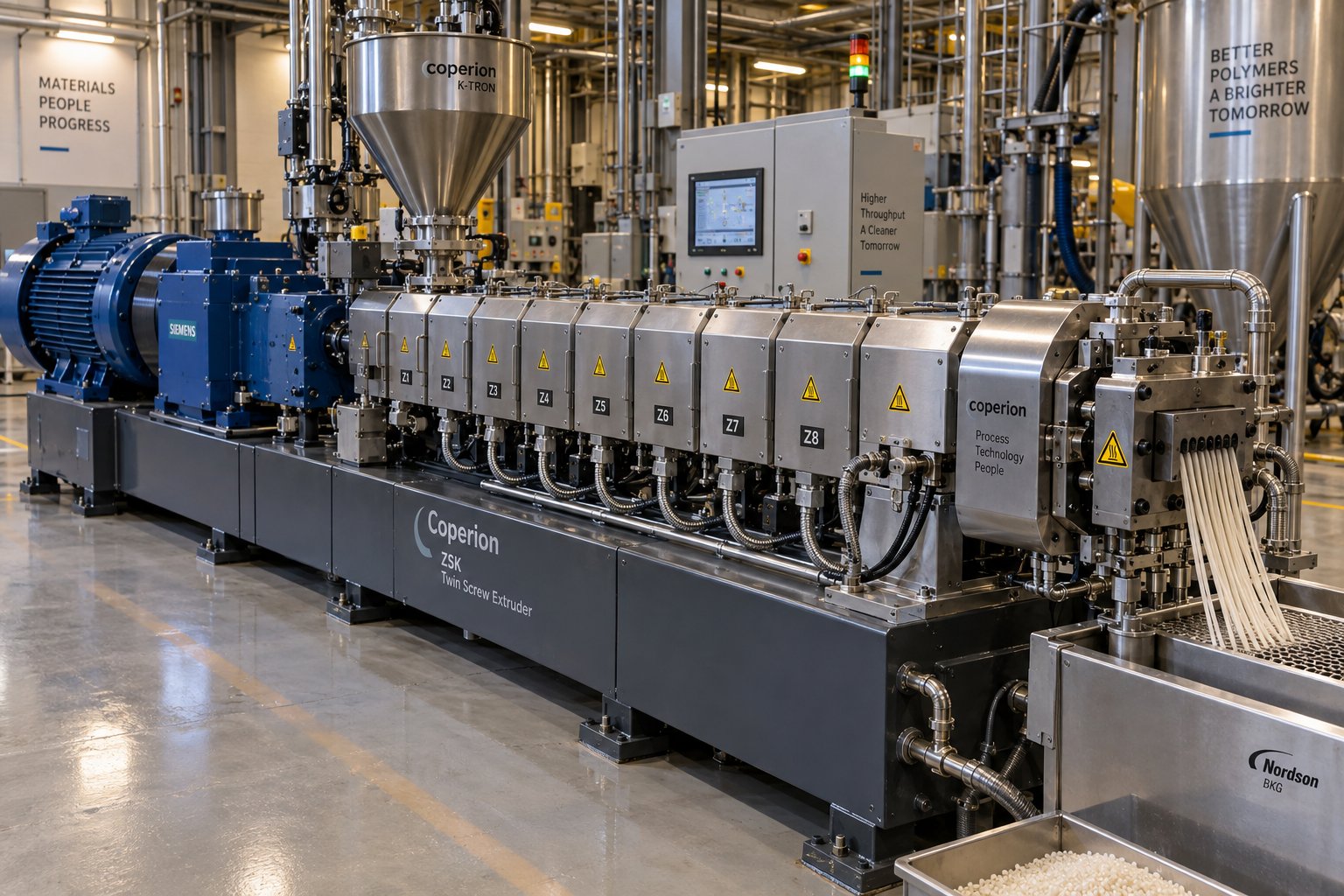
什么是用于造粒的平行双螺杆挤出机?
想象一下,你需要将十几种不同的原料——聚合物树脂、颜料、玻璃纤维、稳定剂——混合成完全均匀的颗粒,每一颗颗粒都必须与前一颗完全相同。单螺杆挤出机在料筒内旋转根本无法实现如此精细的混合控制。正因如此,平行双螺杆挤出机已成为聚合物行业几乎所有领域复合塑料造粒的主力设备。
用于造粒的平行双螺杆挤出机是一种聚合物加工机械,它使用两个直径相同的螺杆,并排安装在八字形机筒内,熔化、混合和输送塑料材料,然后将均质熔体通过模具进行颗粒生产。
这个定义抓住了要点,但真正的意义在于这种配置能够实现什么——以及为什么工程师们一直选择它而不是其他任何替代方案。
定义平行双螺杆挤出机
平行双螺杆挤出机的核心工作原理是:两根相互啮合的螺杆在共用的温控机筒内旋转。机筒内壁呈“8”字形截面,螺杆螺纹在中心重叠,形成两根螺杆之间强烈的相互作用区域。这种啮合结构能够实现正向输送——物料被物理地向前推动,而不是仅仅依靠与机筒壁的摩擦阻力。
最终得到的机器能够同时出色地完成三项任务:熔化固体聚合物、充分混合添加剂或填料,以及产生稳定的压力将熔体推过模头。通过模块化螺杆元件和分段式料筒区域,每项功能都可以独立进行微调,从而为加工商提供其他任何挤出机类型都无法比拟的灵活性。
这与锥形双螺杆挤出机有何不同?在锥形设计中,螺杆从较大的进料端直径逐渐变细至较小的出料端直径。这种设计能够产生自然的压缩效果,但限制了可用的混合长度,并将机器的应用范围限制在较窄的范围内——主要用于PVC干混料加工。相比之下,平行式设计在整个加工长度上保持螺杆直径恒定,使得工程师可以几乎以任何顺序布置输送区、捏合区和排气区。
为什么制粒需要双螺杆技术
Pelletizing is far more than chopping plastic into small pieces. The twin screw extruder pelletizing process requires precise melt homogeneity so that every pellet carries the exact same composition. It demands stable, consistent pressure at the die so pellet size and shape remain uniform across hours of continuous production. And it must accommodate the incorporation of additives — colorants, flame retardants, mineral fillers, reinforcing fibers — without degrading them or the base resin.
Single screw extruders handle conveying and melting reasonably well, but their limited mixing capability makes them a poor fit when compounding and pelletizing happen in a single step. Twin screw systems, especially co-rotating parallel designs, generate both dispersive and distributive mixing forces that break down agglomerates and spread every component evenly through the melt.
The applications you'll encounter span the full spectrum of polymer processing: compounding engineering plastics like nylon and polycarbonate, producing color and additive masterbatch, recycling post-consumer HDPE and LDPE, manufacturing highly filled compounds with 40-80% mineral content, and formulating specialty materials such as biodegradable polymers and thermoplastic elastomers.
The sections ahead go deep into the engineering details that make all of this work — starting with the physical anatomy of the machine itself, component by component.
Anatomy of a Parallel Twin Screw Extruder: Components and Parts
Every parallel twin screw extruder for pelletizing shares a common architecture — a chain of precision-engineered components that each play a distinct role in transforming raw polymer into uniform pellets. Understanding what each part does, and why it matters, gives you the foundation to evaluate machine specifications, troubleshoot production issues, and make smarter purchasing decisions.
Here is a quick-reference list of the major components you will find on a typical system, from the power source all the way to the finished pellet:
- Electric motor
- Torque-distributing gearbox
- Coupling
- Modular barrel sections (with independent heating and cooling)
- Screw elements (conveying, kneading, mixing)
- Breaker plate
- Screen changer
- Die head
- Pelletizer
Each of these components influences pellet quality, throughput, and operational reliability. Let's walk through the most critical ones in detail.
Drive System and Gearbox
The drive system is where everything starts. An electric motor — typically an AC motor with variable frequency drive — supplies the rotational energy that powers the twin screws. But raw motor speed is far too high and torque far too low for direct screw operation. That's where the gearbox steps in.
The gearbox, often called the "power heart" of the extruder, performs three essential functions: it reduces motor speed to the operating range the screws require, multiplies torque to overcome the viscous resistance of the polymer melt, and absorbs the substantial axial thrust loads generated as material is pressurized toward the die. In twin screw designs, the gearbox must also maintain precise angular synchronization between both shafts. Even a fractional timing error under load can cause screw interference and catastrophic mechanical damage.
Why does torque density matter so much for pelletizing? When you process high-viscosity compounds or materials loaded with 40-80% mineral filler, the screws face enormous resistance. Modern high-performance gearboxes deliver torque densities up to 18 Nm/cm³, enabling throughput rates that were previously impossible on torque-limited machines. A practical operating guideline: run at roughly 80% of continuous-duty torque capacity to maintain headroom for process variations and cold-start transients, which can spike 20-40% above steady-state loads.
Barrel Sections and Heating-Cooling Zones
Picture the barrel not as a single tube, but as a series of individual segments bolted together end to end. This modular barrel concept is one of the defining features of co-rotating parallel twin screw extruders, and it gives processors remarkable flexibility.
Each barrel section features its own independent heating and cooling system — typically electric band or cartridge heaters paired with water-cooling channels. This independent zone control is critical because the melt profile along the processing length is anything but uniform. The feed zone needs to stay relatively cool to prevent premature melting and bridging. The melting and mixing zones require precisely elevated temperatures. Downstream sections may need active cooling to prevent thermal degradation of shear-sensitive polymers.
Some barrel segments include specialized openings: feed ports for introducing base resin, side-stuffer ports for downstream filler addition, and vent ports for moisture and volatile removal. The ability to rearrange, add, or remove these segments means the same extruder platform can be reconfigured for entirely different pelletizing applications.
Barrel liner materials deserve attention too. Processing abrasive fillers like glass fiber, calcium carbonate, or carbon fiber rapidly wears conventional steel. Advanced solutions — such as nickel-based tungsten carbide alloy coatings applied through laser cladding — deliver exceptional wear and corrosion resistance, extending barrel service life by 40-60% in demanding applications.
Die Plate and Pelletizer Interface
At the discharge end of the extruder, the homogenized polymer melt passes through a screen changer and breaker plate — which filter out contaminants and equalize flow — before reaching the die plate. The die plate is the final extrusion component, containing precisely machined holes through which the melt exits as continuous strands, droplets, or directly cut pellets, depending on the pelletizing method used.
Die hole diameter, land length, and the number of holes all influence pellet geometry, surface finish, and production rate. The interface between the die and the pelletizer must maintain consistent melt pressure and temperature to produce pellets with uniform size and density. Any pressure fluctuation at this point shows up immediately as irregular pellets.
The choice of pelletizing method — strand cutting, underwater, water ring, or hot face — determines the specific die configuration and downstream equipment required. Each method pairs differently with various polymer types, throughput requirements, and pellet quality targets, a topic that deserves its own detailed examination.
Yet the performance of every component downstream of the screws ultimately depends on what happens inside the barrel. And inside the barrel, screw element design is where the real engineering magic — and the real competitive differentiation — takes place.
Screw Element Design and Modular Configuration
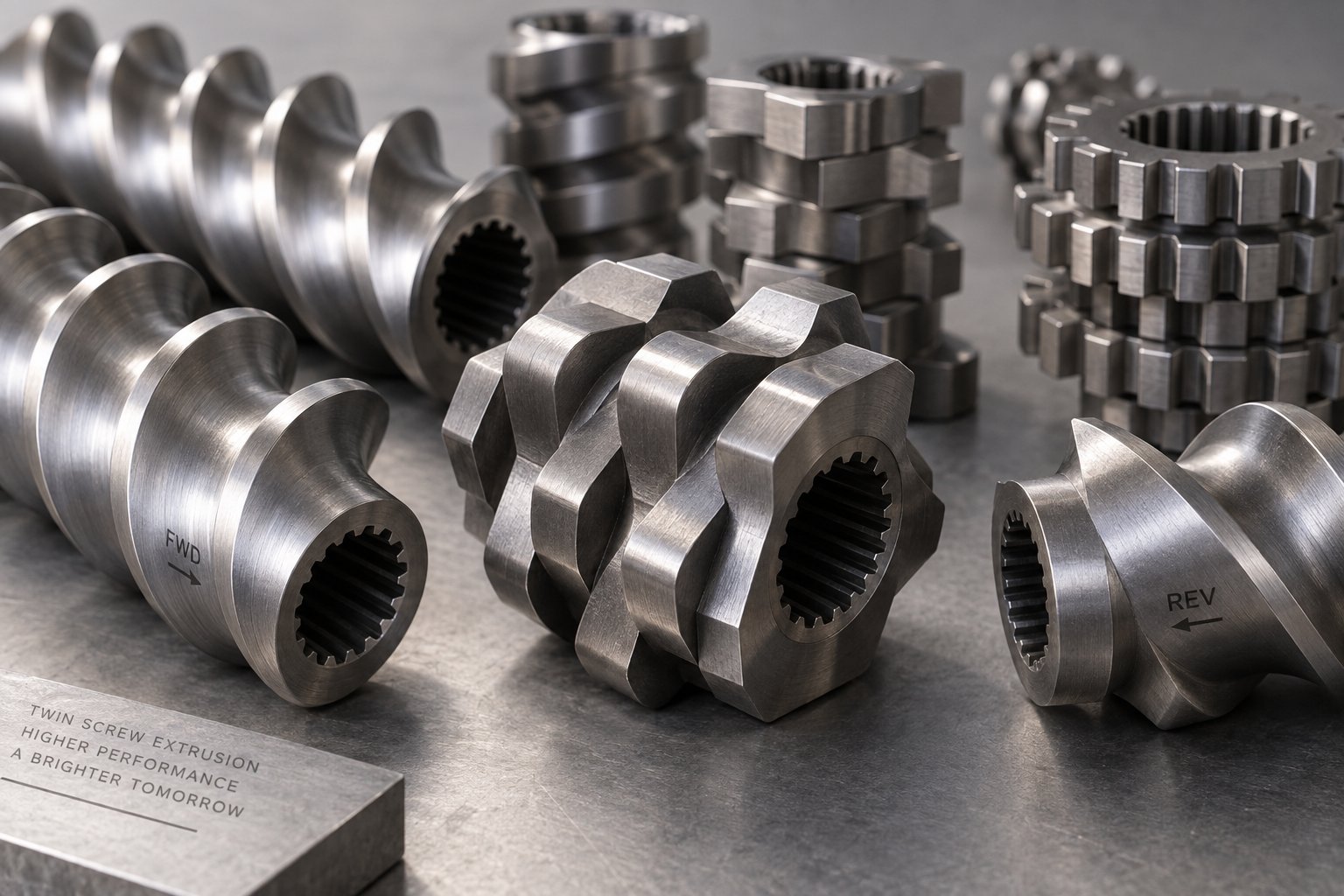
Strip away the motor, the gearbox, and the barrel, and what remains is the true engineering core of any parallel twin screw extruder for pelletizing: the screw elements themselves. These individual segments — each only a few centimeters long — snap onto splined shafts in any sequence the process engineer chooses. Their arrangement dictates how aggressively the machine melts, how thoroughly it mixes, and how much pressure it builds before the die. Get the configuration right, and every pellet leaves the die with identical composition and properties. Get it wrong, and no amount of downstream adjustment can compensate.
Configuring a screw profile is, as NC State Extension researchers describe it, a blend of art and science — because every material exhibits unique flow properties influenced by temperature, shear rate, and extruder geometry. No single gold-standard profile exists that optimizes flow for all materials. That reality is precisely what makes modular screw design so powerful: it turns a fixed machine into an infinitely reconfigurable processing tool.
Types of Screw Elements and Their Functions
Imagine following a stream of polymer pellets and additive powder from the feed throat to the die face. Along that path, the material encounters a carefully sequenced series of screw element types, each engineered for a specific task. Here they are, listed in the order you would typically find them along the screw shaft:
- Forward conveying elements (various pitch sizes) — These are the workhorses of solids transport and melt conveying. Their deep flights grab incoming material and push it downstream without applying significant shear. A larger pitch moves bulk material quickly — ideal for the feed zone where you need high volume throughput. A smaller pitch compresses the material and slows it down, building pressure as the melt approaches the die. Conveying ability decreases as pitch decreases, giving engineers a simple lever for controlling fill level and residence time in each barrel zone.
- Kneading blocks at different stagger angles (30°, 60°, 90°) — These are where the real mixing happens. A kneading block consists of multiple lobed discs stacked along the shaft at a specific angular offset from one disc to the next. The stagger angle is the single most powerful variable controlling shear intensity. At 30°, the block still conveys material forward while gently folding and reorienting the melt — good for distributive blending. At 60°, forward conveying slows significantly and shear forces climb, making these blocks effective for moderate dispersive mixing. At 90° — a neutral conveying angle — the element provides no forward push at all. Material lingers in this zone, experiencing maximum restriction and maximum shear, which is essential for breaking apart stubborn agglomerates like carbon black clusters or tightly bonded pigment particles.
- Reverse conveying elements (left-handed flights) — These elements push material backward, directly opposing the overall forward flow. Sounds counterproductive? It's actually a critical design tool. By creating a localized dam of material, reverse elements generate pressure seals that isolate upstream zones from downstream zones. This isolation enables effective vacuum venting — without a melt seal, applied vacuum would simply pull air through the barrel rather than extracting volatiles from the melt. Reverse elements also extend residence time in the mixing zones immediately upstream, intensifying the mixing work without requiring additional barrel length. Their length is typically kept shorter than one screw diameter to prevent excessive pressure peaks and material degradation.
- Specialized mixing elements (tooth-type and gear-type) — These elements feature rows of protruding teeth or gear-like profiles rather than continuous flights. They repeatedly split and recombine the melt stream, producing excellent distributive blending with minimal additional shear stress. You'll often find them positioned after the primary kneading zones, where the dispersive work is already done and the goal shifts to spreading those dispersed particles uniformly throughout the melt matrix. Toothed mixing elements convey forward while mixing ingredients evenly, making them particularly useful before compression zones where solid and liquid ingredients need final homogenization.
Disc width within kneading blocks adds yet another layer of control. Wider discs plow through the polymer, forming a pool of melt in front of each lobe and smearing materials under high shear — promoting dispersive action. Narrower discs slice through the melt in a scissoring motion, dividing and recombining the flow to promote distributive mixing by essentially stirring the polymer and additives together. This distinction gives engineers fine-grained control over exactly how much energy each zone delivers to the material.
Configuring Screw Profiles for Specific Pelletizing Tasks
Here is where modular screw design truly earns its reputation. The same extruder frame — same motor, same barrel, same gearbox — can be configured for radically different pelletizing applications simply by rearranging the elements on the screw shafts. Consider three real-world scenarios:
Masterbatch pelletizing with stubborn pigments. Dispersing organic pigments or high-structure carbon black demands aggressive kneading zones. A typical screw profile design for masterbatch pelletizing might place a series of wide-disc kneading blocks at 60° and 90° stagger angles in the melting zone, where melt viscosity is still high enough to transmit shear forces into agglomerates. A reverse kneading block or short reverse conveying element caps the mixing section to ensure a high degree of fill, maximizing contact between the kneading discs and the material. L/D ratios of 40:1 to 48:1 are common because multiple kneading, distributive mixing, and venting zones all need physical space along the barrel.
Recycled PET or shear-sensitive polymers. A gentler approach is essential. Too much shear degrades molecular weight, destroys intrinsic viscosity, and produces weak, brittle pellets. The screw profile shifts toward narrow-disc kneading blocks at lower stagger angles — perhaps 30° to 45° — paired with forward-conveying tooth-type mixers for distributive blending. Vacuum venting zones become especially critical for removing residual moisture that would cause hydrolytic degradation. The goal is just enough mixing to homogenize the melt without thermally or mechanically damaging the polymer chain.
Highly filled compounds (40-80% CaCO3 or talc). The challenge here is sheer volume. Massive filler loadings demand extended mixing zones with enough residence time to wet every mineral particle with molten polymer. Side feeders introduce the filler downstream of the initial melting zone to avoid starving the screws of melt lubrication. The screw profile typically features multiple kneading sections of moderate intensity, separated by conveying elements that allow the melt to recover before encountering the next mixing zone.
The beauty of the modular approach? When a production line switches from masterbatch to recycled polyolefin pelletizing, operators can pull the screws, slide off the kneading blocks and conveying elements, and reassemble a completely different profile — all without replacing the shafts, the barrel, or any other major component. This flexibility slashes changeover costs and lets a single extruder platform serve multiple product lines.
Dispersive vs Distributive Mixing in Pelletizing
These two mixing mechanisms sound similar, but they accomplish fundamentally different things — and pellet quality depends on getting the right balance between them.
Dispersive mixing breaks down agglomerates. Picture a cluster of pigment particles held together by cohesive forces. Dispersive mixing applies intense, localized shear stress that exceeds those cohesive forces, fracturing the cluster into its smallest possible particles. Wide-disc kneading blocks at high stagger angles and tight clearances between screw tips and barrel wall generate the energy required for this work.
Distributive mixing spreads already-dispersed particles uniformly throughout the melt. Without it, you could have perfectly broken-down pigment particles concentrated in one region of the melt stream while other regions remain lean. Narrow-disc kneading blocks, tooth-type mixers, and gear-type elements excel at this task because they repeatedly divide and recombine the flow without adding excessive shear energy.
A material can be distributed but not dispersed — pellets full of evenly spaced but still-clumped agglomerates that cause specks in finished parts. Or it can be dispersed but not distributed — fine particles concentrated in streaks rather than spread uniformly, producing blotchy color or inconsistent mechanical properties. As veteran compounding engineer Kenneth Russell explains, you need both dispersive and distributive mixing working in the correct sequence to produce a truly homogeneous compound.
The practical design principle? Place dispersive elements first — where the melt is still viscous enough to transmit high shear forces into particle clusters — and follow them with distributive elements that spread the broken-down particles evenly. Cap each mixing section with a neutral or reverse element to ensure a high degree of fill, because mixing sections work more efficiently and more gently when they are well filled with material. An under-filled kneading zone tends to whip the polymer like a beater, raising melt temperature and potentially damaging shear-sensitive additives or fiber reinforcements.
This balance between dispersive and distributive action is never static. It shifts with every formulation change, every filler loading adjustment, and every carrier resin swap. And it interacts directly with another fundamental design variable that shapes the entire processing envelope: the geometry of the twin screws themselves — specifically, whether those screws co-rotate or counter-rotate.
Co-Rotating vs Counter-Rotating Twin Screw Extruder Geometry Explained
Two parallel screws spinning inside the same barrel can still behave in dramatically different ways — and the difference comes down to a single variable: rotation direction. Spin both screws in the same direction and you get one class of machine. Spin them in opposite directions and you get another with fundamentally different flow patterns, shear characteristics, and application strengths. Choosing the wrong geometry for your pelletizing application doesn't just reduce efficiency — it can make the entire process unworkable.
Understanding these two configurations at a technical level gives production managers and engineers the clarity they need to match machine geometry to material behavior and pellet quality targets.
Co-Rotating Parallel Twin Screw Extruders
In a co-rotating twin screw extruder, both screws turn in the same direction — either both clockwise or both counterclockwise. The screws adopt a fully intermeshing geometry, meaning the flight of one screw fits precisely into the channel of the other. As the screws rotate, polymer is forcibly transferred from one screw to the adjacent screw at the intermeshing region. The material follows an elongated figure-eight path as it moves down the barrel, traveling around one screw, crossing to the next, and repeating the cycle.
This handoff mechanism creates two critical advantages. First, the opposing velocity directions at the screw tips in the intermeshing zone generate high shear stress, which is exactly what you need to break apart pigment agglomerates, disperse nanofillers, or blend immiscible polymer alloys. As Technovel's extrusion engineering team explains, intense shear fields develop both between the screws and between the screw and barrel, while kneading elements add an elongational flow component — together imposing a complex deformation history on the material.
Second, the geometry produces a powerful self-wiping action. Because the flight tip of one screw continuously sweeps the root of the other, accumulated material is scraped away before it can stagnate. You'll notice the practical impact immediately: self-wiping twin screw extruder advantages include a narrow residence time distribution, minimal dead zones, and drastically reduced risk of thermal degradation. When you switch from a dark-pigmented masterbatch to a natural compound, purge time is short because there are virtually no hidden pockets where old material can hide.
These characteristics explain why the co-rotating twin screw extruder for compounding dominates the pelletizing landscape for masterbatch production, engineering plastics, filled compounds, polymer alloys, and reactive extrusion. The combination of high-intensity mixing, efficient self-cleaning, and high throughput capacity makes it the most versatile platform available.
Counter-Rotating Parallel Twin Screw Extruders
Flip one screw's rotation direction and the physics change substantially. In a counter-rotating twin screw extruder, the left screw rotates clockwise while the right screw rotates counterclockwise — or vice versa. At the intermeshing zone, both screw surfaces move in the same direction, drawing material inward and compressing it between the screws rather than shearing it across from one shaft to the other.
Imagine two rollers in a calendar press squeezing a sheet of material between them — that's essentially the calendering effect that occurs at the intermeshing region. Material undergoes repeated compressive and elongational deformation under relatively gentle conditions. Shear stress stays lower than in co-rotating designs, and the associated shear-induced heat generation remains correspondingly modest.
This gentler processing environment is not a limitation — it's a deliberate engineering advantage for specific materials. Raw material moves forward in enclosed, C-shaped chambers formed between the screw flights and the barrel wall, creating a positive displacement pumping action similar to a gear pump. The result is stable extrusion pressure even at low screw speeds, which is essential for materials that degrade rapidly when overheated.
The counter-rotating twin screw extruder for PVC pelletizing is the classic example. Rigid PVC has a notoriously low thermal decomposition temperature paired with poor melt flow. Push it through an aggressive co-rotating machine and you risk degradation, discoloration, and acid gas release. The counter-rotating configuration allows operators to maintain low barrel temperatures, minimize shear heating, and still achieve adequate dispersion of stabilizers and processing aids through the calendering mechanism. Beyond PVC, you'll find counter-rotating designs in profile extrusion and applications where thermally sensitive additives demand minimal mechanical energy input.
One practical consideration worth noting: counter-rotating designs use two screws with opposite thread directions, so they cannot be interchanged during installation. Co-rotating machines use identical screws, simplifying inventory and eliminating the risk of incorrect assembly.
Side-by-Side Comparison
The following table distills the key differences between these two configurations into a format you can reference quickly when evaluating which geometry fits your pelletizing requirements:
| Criterion | Co-Rotating | Counter-Rotating |
|---|---|---|
| Mixing Intensity | High — strong shear and elongational flow fields | Moderate — relies on calendering and compressive deformation |
| Shear Level | High, especially at the intermeshing zone | Low to moderate, minimizing shear-induced heat |
| Self-Wiping Capability | Excellent — flight tips continuously sweep opposing screw root | Limited — same-direction surface movement reduces wiping action |
| Throughput Capacity | High — efficient conveying and flexible degree of fill | Lower — positive displacement limits volumetric output |
| Typical Pelletizing Applications | Compounding, masterbatch, engineering plastics, polymer alloys, reactive extrusion | PVC pelletizing, profile extrusion, heat-sensitive formulations |
| Material Suitability | Broad — polyolefins, nylons, PC, PET, TPE, filled compounds | Narrow — primarily PVC and thermally sensitive polymers |
| Residence Time Distribution | Narrow and uniform — critical for degradation-sensitive processes | Broader — C-shaped chambers create more variation |
How Geometry Affects Pellet Quality
All of these geometric differences ultimately show up in one place: the pellet itself. Here's how the choice between co-rotating and counter-rotating geometry connects to the quality metrics that matter most on the production floor.
Melt homogeneity. Co-rotating machines produce a more uniformly mixed melt because the figure-eight flow path forces every molecule through multiple high-shear and reorientation events. For pelletizing applications where additive distribution must be absolutely consistent — think color masterbatch with tight Delta E specifications or flame-retardant compounds requiring exact loading percentages — this homogeneity advantage is decisive.
Additive distribution. Counter-rotating extruders disperse additives through compressive calendering rather than high-shear kneading. This works well when the additives are easy to incorporate and the formulation doesn't require breaking apart tightly bonded agglomerates. However, when you're dispersing high-structure carbon black, nano-scale fillers, or stubborn pigment clusters, the higher shear energy available in a co-rotating profile delivers noticeably better dispersion and fewer visual defects in the finished pellet.
Thermal degradation risk. This is where counter-rotating designs earn their place. Every joule of mechanical energy that the screws impart to the polymer converts partly into heat. Co-rotating machines, with their higher shear intensity, generate more viscous dissipation — which raises melt temperature. For PVC or other polymers with narrow processing windows, even a 10-15 degree Celsius overshoot can trigger chain scission, discoloration, or release of corrosive byproducts. Counter-rotating geometry keeps the energy input low and predictable, protecting vulnerable materials throughout the pelletizing process.
Final pellet consistency. Uniform pellets require uniform melt pressure at the die. Co-rotating extruders achieve this through careful screw profile design and high-speed operation that smooths out pulsation. Counter-rotating designs achieve pressure stability through their inherent positive-displacement pumping action, which can be advantageous at low throughput rates where co-rotating machines might exhibit pressure surges.
The geometry decision, then, is never abstract — it flows directly from the material you're processing, the additives you're incorporating, and the pellet specifications your customers demand. Yet geometry alone doesn't determine the processing envelope. The length of barrel available for feeding, melting, mixing, venting, and pressure building — expressed as the L/D ratio — and the method used to cut the melt into pellets at the die face play equally critical roles in shaping the final product.
L/D Ratio and Pelletizing Method Selection
Two design decisions shape the output of every parallel twin screw extruder for pelletizing more than any other: how much barrel length is available for processing, and how the melt is converted into pellets at the die face. Engineers often evaluate these factors separately — one during extruder specification, the other during downstream equipment selection. In reality, they are deeply interdependent. The melt quality arriving at the die determines which pelletizing method will even work, and the pelletizing method's pressure and flow requirements influence how much processing length is needed upstream. Treating them as a unified system, rather than isolated choices, is the difference between a line that runs flawlessly and one plagued by inconsistent pellets.
How L/D Ratio Shapes the Pelletizing Process
The twin screw extruder L/D ratio for pelletizing — the ratio of screw length to screw diameter — is the single number that defines how much processing real estate is available along the barrel. Every functional zone competing for space on that barrel must fit within the total L/D: solids feeding, melting, kneading and mixing, side feeding of fillers or fibers, vacuum venting for moisture and volatiles, and the final pressure-building section that pushes a uniform melt stream into the die.
Sounds like a lot of zones to pack into one barrel? It is. And the consequences of running short on L/D show up directly in pellet quality.
In compounding extruders, the L/D ratio typically ranges from 20:1 to 40:1, depending on the specific requirements of the application. A shorter ratio — say 24:1 to 32:1 — may work for straightforward recycling tasks where a single resin is remelted with minimal additive incorporation and one atmospheric vent. The processing demands are modest: melt the polymer, remove some moisture, build die pressure, and pelletize.
Push into more intensive compounding territory, and the picture changes dramatically. Producing color masterbatch with multiple pigment additions, or engineering plastic compounds with glass fiber reinforcement and vacuum degassing, demands L/D ratios of 36:1 to 48:1. Why? Because each additional function — a second kneading zone, a side-feeder port, a vacuum vent — needs physical barrel length to work effectively. A higher L/D ratio provides more time for material processing, better mixing, and more efficient devolatilization, all of which are essential for complex formulations.
Here is a practical way to think about what each L/D range supports:
- 24:1 to 32:1 — Simple remelting and pelletizing of clean, pre-compounded resin or basic recycling streams. One feed zone, one mixing section, one vent, and a pressure-building zone.
- 32:1 to 40:1 — Standard compounding with moderate additive loading, one or two kneading zones, a side feeder for mineral fillers, and at least one vacuum vent. This range covers the majority of filled compound and general-purpose masterbatch production.
- 40:1 to 48:1 — Intensive compounding requiring multiple injection points (liquid additives, two-stage filler feeding), extended mixing sections, and two or more vacuum venting ports. Engineering plastics like nylon and PET with high moisture sensitivity, or heavily pigmented masterbatch requiring aggressive dispersive mixing, typically land here.
What happens when L/D is insufficient for the application? The extruder simply runs out of room. Mixing zones get compressed and fail to achieve full dispersion. Venting zones are too short to extract all volatiles, leaving residual moisture that causes bubbles and porosity in finished pellets. The pressure-building section shrinks, leading to unsteady die pressure and inconsistent pellet size. In some cases, engineers attempt to compensate by increasing screw speed, but this raises melt temperature and risks thermal degradation — trading one defect for another.
The trade-off isn't free in the other direction either. A longer barrel requires more capital investment, occupies more floor space, and demands more energy to drive the screws through the additional material. Manufacturers must balance the need for processing length against cost and space considerations, which is why selecting the right L/D ratio for your specific pelletizing application — rather than defaulting to the longest available — represents a genuine engineering optimization.
Strand Pelletizing vs Underwater Pelletizing vs Water Ring vs Hot Face Cutting
Once the melt exits the barrel with the proper homogeneity and pressure, the pelletizing system takes over. Four major methods dominate the industry, and each produces pellets with distinctly different geometries, surface qualities, and production characteristics. Understanding the strand pelletizing vs underwater pelletizing comparison — along with water ring pelletizer vs hot face cutting differences — is essential for anyone deciding how to choose a pelletizing method for plastic compounding.
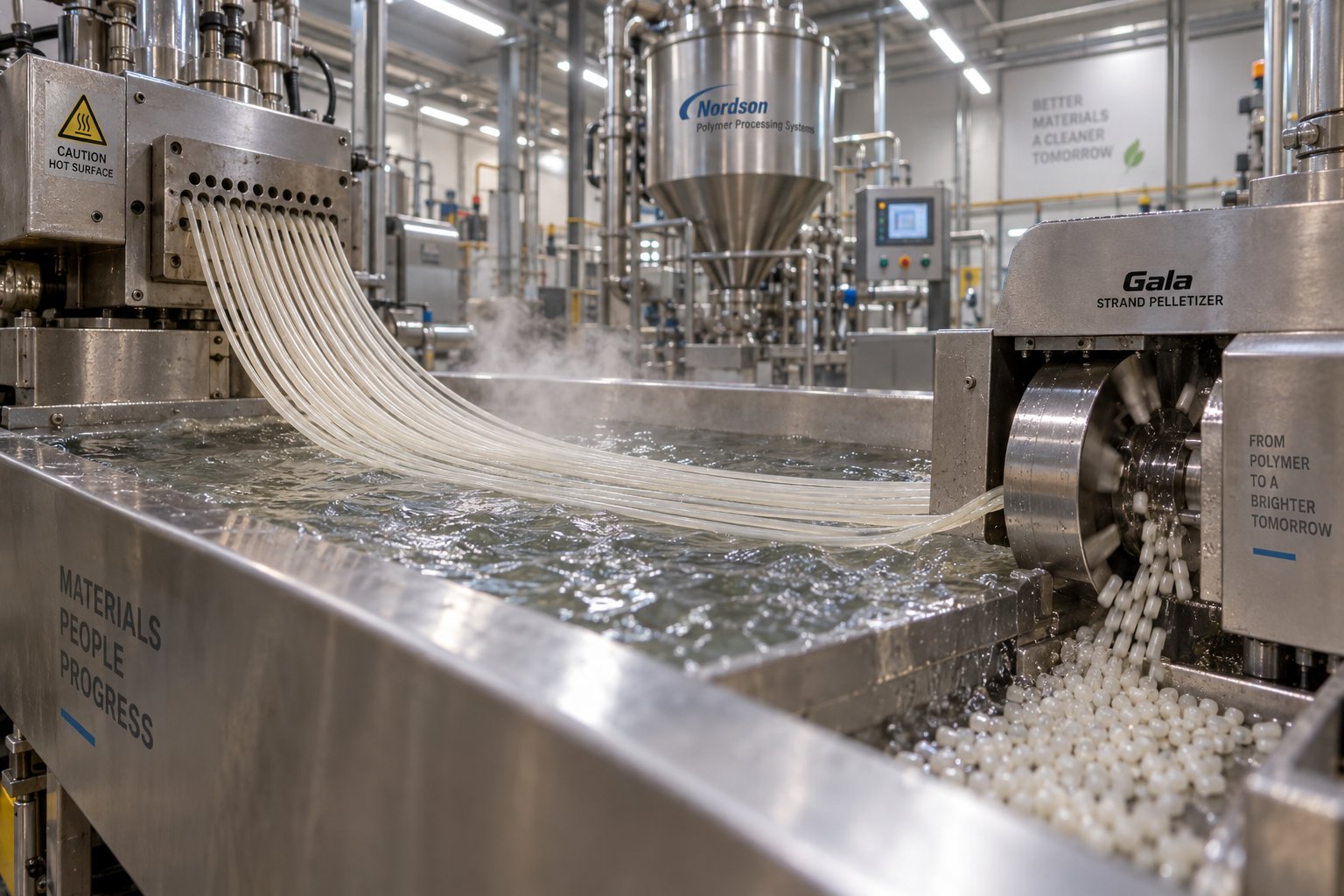
Strand pelletizing is the most straightforward approach. Molten polymer exits multiple die holes as continuous strands, which travel through a water bath or water slide for cooling. After solidifying, the strands pass through a de-watering unit or air knife and enter a strand pelletizer, where rotating blades cut them into short cylindrical pellets. This method is the lowest in capital cost, handles a wide range of polymers, and allows fast changeovers — making it particularly appropriate for toll compounders and operations with frequent job changes. The trade-offs? Strand pelletizing is more labor-intensive (imagine manually stringing up to 75 strands across guide rolls at every startup), generates more dust and fines because the polymer is cut in its solid state, and produces cylindrical pellets whose flat ends can stick together and cause bridging in hoppers.
Underwater pelletizing (UWP) cuts molten polymer directly at the die face within a chamber completely filled with process water. As each molten droplet separates from the die hole, surface tension forces shape it into a near-perfect sphere. The process water transports the pellets through an agglomerate catcher to a centrifugal dryer. UWP systems offer the highest throughput capacity — up to 70,000 lb/hr — produce spherical pellets with excellent flow characteristics and high bulk density, and generate minimal dust and fines. They also provide the greatest scope for automation, with PLC control governing blade sharpening, in-line die-plate grinding, and startup sequencing. The primary disadvantages are higher capital cost, greater mechanical complexity, and the risk of die "freeze-off" — where process variations cause polymer to solidify inside the die holes.
Water ring pelletizing (WRP) is also a die-face cutting method, but with a crucial difference: the cutting chamber is not fully submerged. Instead, a ring of water fed tangentially into the chamber cools and transports the pellets after they are cut by rotating knives. The pellets emerge with a rounded but flattened shape, similar to aspirin tablets. Water ring pelletizers are the most compact of the major pelletizing systems and cost less than UWP setups. They are significantly less sensitive to process variations and don't suffer from die freeze-off. The catch? WRPs are limited chiefly to high-melt-strength materials like polyolefins and polystyrene, and their throughput capacity tops out around 11,000 lb/hr — far below underwater systems.
Hot face cutting slices the melt at the die face using knives that contact the die plate directly, then cools the pellets with either an air stream or a water spray. Air-cooled hot face systems blow the cut pellets through ducting to cyclone separators, with water-jacketed piping and silos aiding temperature control. Water-cooled versions drop the pellets into a water stream for transport to a centrifugal dryer, much like a water ring setup. Hot face pelletizers offer precise control over pellet size and shape and handle a broad polymer range. However, the heated die plate consumes more energy, and the direct thermal contact can cause some degradation of heat-sensitive polymers if operating parameters are not carefully optimized.
The following table provides a side-by-side comparison to help you evaluate each method against your specific production requirements:
| Criterion | Strand Pelletizing | Underwater Pelletizing | Water Ring Pelletizing | Hot Face Cutting |
|---|---|---|---|---|
| Pellet Shape | Cylindrical | Spherical | Rounded/lenticular (aspirin-tablet shape) | Semi-spherical to irregular, depending on cooling method |
| Throughput Range | Up to ~44,000 lb/hr | Up to ~70,000 lb/hr | Up to ~11,000 lb/hr | Low to moderate (application-dependent) |
| Capital Cost | Lowest | Highest | Moderate | Low to moderate |
| Material Suitability | Broad — most thermoplastics, filled compounds, engineering plastics | Broadest — virtually any polymer including hot melts and sticky formulations | Limited — primarily high-melt-strength polyolefins and PS | Broad — polyolefins, filled compounds, waxes |
| Cooling Method | Water bath or water slide, then air knife | Fully submerged process water in cutting chamber | Tangential water ring in cutting chamber | Air stream or water spray after die-face cut |
| Typical Applications | Toll compounding, frequent changeovers, filled compounds, engineering plastics | High-volume resin production, masterbatch, micropellets, recycling | Polyolefin recycling, reclaim operations | Waxes, hot melts, certain filled polyolefin compounds |
| Dust and Fines | Higher — solid-state cutting generates more particulate | Very low — molten-state cutting minimizes dust | Low — molten-state cutting | Low to moderate — molten-state cutting, but air cooling can generate some fines |
| Automation Level | Low — labor-intensive strand threading | High — PLC-controlled startup, blade management, and process monitoring | Moderate — pushbutton start/stop, adjustable cutter RPM | Moderate — simpler mechanical design |
Matching L/D and Die Design to Your Application
Here's the critical insight that ties these two topics together: the L/D ratio determines the quality of the melt arriving at the die, and the pelletizing method determines what you can do with that melt once it gets there. Neither decision makes sense in isolation.
Consider a practical example. An underwater pelletizer demands steady, high melt pressure and consistent viscosity at the die plate — any fluctuation causes freeze-off or malformed pellets. Achieving that stability requires adequate L/D for thorough mixing, complete devolatilization, and a sufficiently long pressure-building zone upstream of the die. Skimp on L/D, and the melt arrives at the die with inconsistent temperature, residual volatiles, and pressure surges that the UWP simply cannot tolerate.
Strand pelletizing is more forgiving of melt quality variations because the polymer solidifies in a water bath before cutting. Minor pressure fluctuations may change strand diameter slightly, but the impact on final pellet quality is less dramatic than in die-face cutting methods. This tolerance is one reason strand systems remain popular with compounders running shorter-L/D extruders or processing materials with naturally variable rheology, such as post-consumer recycled streams.
Water ring pelletizers, limited to high-melt-strength materials, pair naturally with shorter to mid-range L/D ratios because the materials they process — primarily polyolefins — typically require less intensive mixing and fewer venting stages. The positive melt-strength of the polymer prevents die drool and supports clean die-face cutting without the full submersion that UWP requires.
Hot face cutting systems fall somewhere in the middle. Air-cooled versions suit applications where water contact is undesirable — moisture-sensitive materials or certain wax compounds — and they can operate with moderate melt pressure. Water-cooled hot face systems approach the capability of water ring pelletizers while offering broader material compatibility.
The decision framework, then, follows a logical chain: start with the material's processing requirements (shear sensitivity, additive loading, moisture content) to determine the screw profile and minimum L/D ratio. Then evaluate the pellet specifications your downstream customers or processes demand (shape, size, bulk density, dust tolerance) to select the pelletizing method. Finally, confirm that the die design — hole count, hole diameter, land length — bridges the extruder's melt output to the pelletizer's operating window. When all three elements align, the line runs at its engineered capacity with minimal waste and consistent pellet quality.
Of course, the melt doesn't arrive at the screw elements by magic. How raw materials enter the extruder — and how moisture and volatiles leave it along the way — are upstream and midstream functions that exert just as much influence over the finished pellet as anything happening at the die face.
Feed Systems and Degassing Zones in Twin Screw Pelletizing Extruders
Every pellet starts as raw material dropping into a feed throat — and every defect-free pellet depends on moisture and volatiles being pulled out of the melt before it reaches the die. These two functions sit at opposite ends of the barrel, yet they share a common trait: get either one wrong, and no amount of screw optimization or die tuning can rescue your pellet quality. Feeding controls what goes into the process. Degassing controls what comes out of it. Together, they frame the entire processing window.
Gravimetric vs Volumetric Feeding Systems
Material enters the extruder through a feeder mounted above the barrel's feed throat, and the type of feeder you choose determines how precisely you control the composition of every pellet produced. Two fundamentally different approaches dominate the industry.
A volumetric feeder dispenses material based on volume. A rotating screw, vibratory tray, or rotary valve moves a fixed volume of material per revolution or cycle, and the system assumes a constant bulk density to estimate the mass delivered. The appeal is simplicity and lower upfront cost. Volumetric feeders work well when material characteristics remain relatively consistent and minute variations in weight are acceptable — for example, remelting clean, uniform production scrap where the composition is already locked in.
A gravimetric feeder measures the actual weight of material in real time as it enters the process. A load cell beneath the hopper continuously monitors mass loss, and a control loop adjusts the feed rate to maintain a precise weight-per-unit-time target. This dynamic adjustment compensates for changes in bulk density, bridging, or material flow variations — delivering unparalleled accuracy in the final pellet composition.
When does the higher cost of gravimetric feeding pay for itself? Consider masterbatch production, where a 0.5% deviation in pigment loading shows up as visible color shift in the customer's molded parts. Or engineering plastic compounds where flame retardant loading must hit precise regulatory thresholds. In these applications, gravimetric precision isn't optional — it's the difference between saleable product and scrap. For basic recycling lines processing a single-component stream, a volumetric feeder often provides adequate control at a lower investment.
Side Feeders and Liquid Injection for Additives
Not everything enters through the main feed throat. In fact, many of the most critical additives in a pelletizing formulation are deliberately introduced downstream — after the base polymer has already melted — through side feeders and liquid injection ports.
Why not just dump everything in at the top? Imagine feeding chopped glass fiber into the main hopper alongside polymer pellets. The fiber would pass through every kneading block and mixing zone in the barrel, and by the time the melt reached the die, those carefully engineered reinforcing fibers would be ground down to dust. As glass fiber compounding research demonstrates, long glass fibers are typically fed from a top port in the middle section of the barrel, while short glass fibers enter through a side feeder — both positioned downstream of the primary melting and kneading zones. This approach preserves fiber length, which directly determines the mechanical strength of the finished pellet.
The same logic applies to mineral fillers like calcium carbonate, talc, and barium sulfate. Side stuffers — twin-screw devices mounted perpendicular to the main barrel — force high volumes of filler into an already-molten polymer stream. Introducing these materials after the melt zone prevents them from absorbing heat energy needed for melting, avoids starving the screws of the polymer lubrication they require for proper conveying, and reduces abrasive wear on upstream screw elements.
Liquid injection ports handle a different category of additives: processing oils, silane coupling agents, liquid colorants, peroxide crosslinking agents, and plasticizers. These are metered by precision pumps directly into the melt stream through injection nozzles installed in specific barrel zones. Placement matters — inject a coupling agent too early and it may volatilize before contacting the filler surface; inject it too late and it won't have enough mixing length to coat every particle.
A typical pelletizing line might use several of these feed points simultaneously. Here is a common configuration for a filled compound production line:
- Main hopper — base resin pellets and powdered stabilizers via gravimetric feeder
- First side feeder — mineral filler (CaCO3 or talc) introduced into the melt zone
- Downstream side feeder — chopped glass or carbon fiber added after the primary kneading section
- Liquid injection pump — coupling agents, processing oils, or liquid colorants metered into a designated barrel zone
Each feed point corresponds to a specific barrel opening and a screw profile zone designed to incorporate that material efficiently. The modular barrel concept discussed earlier makes this possible — barrel segments with side-stuffer ports or injection fittings can be positioned wherever the formulation demands.
Degassing and Venting Zones for Pellet Quality
Here is where many pelletizing operations succeed or fail — often without operators fully understanding why. Moisture, trapped air, residual monomers, and volatile organic compounds all remain dissolved or entrained in the polymer melt under the high pressures inside the barrel. If these gases are not extracted before the melt reaches the die, they expand as pressure drops at the die exit, creating bubbles, porosity, surface pitting, and internal voids in the finished pellet.
The consequences go beyond cosmetics. Porous pellets have lower bulk density, causing inconsistent feeding in downstream injection molding or extrusion processes. Moisture trapped in nylon or PET pellets triggers hydrolytic degradation during reprocessing, reducing molecular weight and mechanical properties. Volatile residues in recycled plastic pellets can produce objectionable odors in consumer products. Adequate degassing isn't a nice-to-have — it's a prerequisite for producing pellets that meet specification.
Twin screw extruders use two types of venting to address this challenge:
Atmospheric vents are simple openings in the barrel — typically positioned after the first melting and mixing zone — that allow gases to escape to ambient pressure. They are effective for removing large volumes of trapped air from powder feeds or initial moisture flash from moderately wet materials. No external equipment is required beyond a vent port cover designed to prevent material from escaping.
Vacuum vents apply negative pressure — typically 50 to 200 mbar absolute — to the melt surface through a barrel port connected to a vacuum pump and collection system. This dramatically lowers the boiling point of residual moisture and volatile compounds, pulling them out of the melt far more aggressively than atmospheric venting alone. The vacuum venting zone in a pelletizing extruder is, as Coperion's engineering team explains, frequently positioned right before the pressure build-up zone at the extruder discharge, where its main function is to release gases, moisture, or residual monomers that would otherwise promote void formation within the pellets.
But a vacuum port alone doesn't guarantee effective degassing. The screw profile must create a melt seal upstream of each vent — a fully filled zone that prevents vacuum from pulling air backward through the barrel instead of extracting volatiles from the melt. This is exactly where those reverse conveying elements discussed in the screw design section earn their keep. A short left-handed flight element positioned just upstream of the vent creates a dam of material that seals the barrel, while the downstream screw section uses large-pitch forward conveying elements to keep the barrel only partially filled beneath the vent port. This partially filled condition exposes maximum melt surface area to the vacuum, dramatically improving volatile extraction efficiency.
Processing recycled plastics makes effective degassing even more critical. Post-consumer HDPE and LDPE streams carry residual moisture, printing inks, adhesive residues, and decomposition products from contaminated feedstock. A robust degassing system for recycled plastic pelletizing often requires both an atmospheric vent in the early barrel zones and one or two vacuum venting stages downstream. Without this multi-stage approach, volatiles that survive the first vent contaminate the pellets with odor, discoloration, or structural defects.
Moisture-sensitive engineering polymers like PET and nylon (PA6, PA66) present a related but distinct challenge. Even with pre-drying, residual moisture in the hundreds-of-ppm range can cause measurable molecular weight loss during melt processing. Vacuum venting positioned after the primary mixing zone strips this residual moisture before the polymer reaches the die, protecting intrinsic viscosity and ensuring the pellets perform as expected in the customer's downstream process.
When troubleshooting degassing problems, operators should first check whether the melt viscosity has changed compared to previous runs — a lower-viscosity melt is more likely to blow up into the vent port. If blockages occur, verifying that no kneading elements sit directly below the vacuum port and checking screw elements for wear are both essential diagnostic steps. Abrasion on elements near the vent often indicates that the barrel liner or screw metallurgy is not matched to the abrasive content of the material being processed.
Feeding, additive incorporation, and degassing collectively define the upstream and midstream processing environment. They determine the composition, cleanliness, and uniformity of the melt long before it reaches the die. Yet these functions don't operate in isolation — they interact with every other design variable, from screw geometry and L/D ratio to barrel metallurgy and pelletizing method. That interconnectedness raises a natural question: how does the parallel twin screw extruder stack up against alternative machine architectures when all of these factors are weighed together?
Parallel Twin Screw vs Alternative Extruder Types for Pelletizing
Selecting an extruder architecture is one of the highest-stakes decisions a compounder or recycler can make. The machine you choose locks in your mixing ceiling, your throughput range, your material flexibility, and your capital commitment for years — sometimes decades. A parallel twin screw extruder for pelletizing is the most versatile option on the market, but it's not the only option. Single screw extruders, conical twin screw extruders, and tandem extrusion lines each occupy a distinct niche. Understanding exactly where those niches begin and end helps you invest wisely rather than overspend on capability you don't need — or, worse, underspend and discover you can't process the materials your customers demand.
Parallel Twin Screw vs Single Screw Extruders
A single screw extruder is, at its core, a conveying and melting device. One screw rotates inside a smooth-bore barrel, relying on frictional drag between the polymer and the barrel wall to move material forward. It melts efficiently, builds pressure predictably, and costs significantly less than any twin screw system. For pelletizing pre-compounded materials — resins that have already been mixed, stabilized, and homogenized in a previous step — a single screw machine can deliver perfectly acceptable results.
The limitation becomes obvious the moment you ask a single screw to compound and pelletize in one step. Its mixing capability is inherently restricted. Without a second intermeshing screw generating the shear fields and elongational flows discussed earlier, a single screw extruder cannot break apart pigment agglomerates, uniformly distribute glass fibers, or blend immiscible polymer alloys. You'll notice uneven additive distribution, streaky color, and inconsistent mechanical properties in the finished pellets. As a general comparison confirms, twin screw systems offer better mixing, venting, reaction capability, and self-cleaning performance than their single screw counterparts — advantages that are non-negotiable for compounding pelletizing operations.
There is one scenario where a single screw extruder shines in a pelletizing context: as the second stage in a tandem extrusion line, where its job is purely to stabilize melt flow and build die pressure after a twin screw extruder has already done the compounding work. More on that shortly.
Parallel vs Conical Twin Screw Extruder Comparison
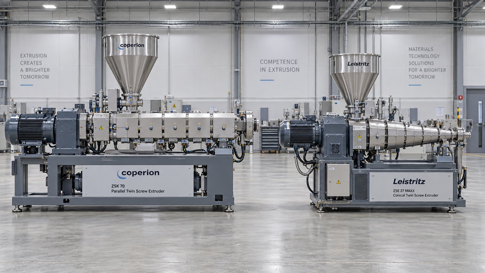
Conical twin screw extruders use two tapered screws — large diameter at the feed end, narrowing toward the discharge. This tapering geometry naturally compresses the material as it travels forward, generating high pressure without requiring dedicated pressure-building screw elements. The conical design also allows a larger center distance between screws at the feed end, improving intake of bulky, low-density powders like PVC dry blends.
Sounds useful — so where does it fall short? The taper progressively reduces the available channel volume along the barrel, which compresses the mixing zone into a short, fixed section. Unlike a parallel twin screw extruder's modular screw elements that can be rearranged for any application, a conical screw is manufactured as a single piece with a fixed profile. Once it is designed and built, you cannot swap kneading blocks, add distributive mixers, or extend the venting zone. If you want to switch from PVC to polypropylene-based masterbatch, you need an entirely new screw — not just a rearrangement of elements on the same shaft.
Throughput capacity is another constraint. The conical geometry limits screw speed compared to parallel designs because the smaller discharge end restricts volumetric output. The result is a machine that excels in its specific niche — PVC compounding, PVC profile direct extrusion, and certain high-filler dry-blend applications — but lacks the versatility that modern compounding operations demand. A processor who plans to run multiple formulations across different polymer families will find the parallel design pays for its higher initial cost many times over in operational flexibility.
Tandem Extrusion Line vs Twin Screw Pelletizing
A tandem extrusion system — also called a two-stage extruder — pairs a co-rotating twin screw extruder with a downstream single screw extruder. The twin screw stage handles intensive mixing and compounding. The single screw stage takes over for devolatilization, melt stabilization, and pressure buildup before the die.
Why add the complexity and cost of a second extruder? In certain demanding applications, the tandem approach offers genuine advantages. Each extruder operates in its optimal torque and speed range, which reduces overall energy consumption. The single screw stage provides additional residence time for vacuum degassing — critical when processing heavily contaminated recycled polymers or moisture-laden engineering plastics. Melt temperature drops because energy input is distributed across two machines rather than concentrated in one, minimizing thermal degradation and improving color stability.
The trade-offs are practical and real. A tandem line requires roughly double the floor space, two independent drive systems, a precisely engineered melt transfer connection between stages, and more complex process controls. Capital cost rises substantially. For applications where a properly configured single-stage parallel twin screw extruder with adequate L/D can achieve the same melt quality and throughput, the added investment is hard to justify.
When does tandem extrusion earn its place? Filler masterbatch production at extremely high loading levels (60-80% CaCO3), recycled polymer pelletizing where extensive degassing is essential, and biodegradable plastic compounding where thermal sensitivity demands the gentlest possible processing all represent scenarios where the two-stage approach delivers measurable quality and efficiency gains over a single twin screw line.
Decision-Making Comparison: All Four Extruder Types
The following table consolidates the key selection criteria into a single reference. Use it as a starting point for matching your pelletizing application to the best extruder type for plastic compounding and pelletizing:
| Criterion | Parallel Twin Screw | Single Screw | Conical Twin Screw | Tandem (Twin + Single) |
|---|---|---|---|---|
| Mixing Capability | Excellent — modular kneading and distributive elements | Limited — primarily drag-flow conveying | Moderate — fixed screw profile, short mixing zone | Excellent — twin screw stage handles all compounding |
| Throughput Range | Wide — scalable from lab to 20+ tons/hr | Moderate to high for remelting tasks | Low to moderate — constrained by taper geometry | High — optimized two-stage flow |
| Shear Control | Highly adjustable via screw element selection | Minimal control — fixed screw geometry | Limited — dictated by fixed taper design | High — low-shear single screw stage reduces total shear input |
| Material Suitability | Broadest — polyolefins, engineering plastics, TPE, masterbatch, recycled streams | Pre-compounded resins, single-polymer recycling | Primarily PVC dry blends, some high-filler compounds | Recycled polymers, filler masterbatch, heat-sensitive compounds |
| Capital Cost Level | Moderate to high | Lowest | Low to moderate | Highest |
| Footprint | Compact for its capability | Compact | Compact | Large — two extruders plus transfer system |
| Ideal Pelletizing Applications | Compounding + pelletizing in one step, masterbatch, engineering plastics, filled compounds, recycling | Pelletizing pre-mixed materials, simple remelting | PVC pelletizing, PVC profile extrusion | High-filler masterbatch, contaminated recycling, biodegradable compounds |
Notice a pattern? The parallel twin screw extruder occupies the widest application band. It can handle nearly every pelletizing task a single screw or conical machine can do, while also covering demanding compounding applications that neither alternative can touch. The tandem system matches or exceeds its mixing and degassing performance but at substantially higher cost and complexity. For the vast majority of compounders, recyclers, and masterbatch producers, a well-configured parallel twin screw line represents the optimal balance of versatility, performance, and investment.
Of course, choosing the right extruder architecture is only half the equation. The materials you feed through that extruder — their thermal behavior, viscosity, filler loading, and sensitivity to shear and moisture — impose their own specific demands on barrel metallurgy, screw element selection, and pelletizing method. Each polymer family writes its own set of processing rules.
Material-Specific Pelletizing Considerations for Twin Screw Extruders
Every polymer family arrives at the feed throat with its own personality — a unique combination of melt viscosity, thermal stability, moisture sensitivity, and abrasive potential that rewrites the processing playbook. A screw configuration that produces flawless nylon pellets will destroy recycled LDPE. A barrel liner that shrugs off neat polypropylene will erode in weeks under 70% calcium carbonate loading. Matching your twin screw extruder barrel, screw elements, venting strategy, and pelletizing method to the specific material you're processing isn't just good practice — it's the dividing line between a profitable operation and one bleeding money through scrap, downtime, and customer complaints.
Engineering Plastics and High-Temperature Polymers
Nylon (PA6 and PA66), PET, and polycarbonate share a common trait that makes them rewarding and punishing to pelletize: they demand high processing temperatures while being acutely sensitive to moisture, residence time, and thermal history. Get the details right and you produce high-performance pellets commanding premium prices. Miss any one detail and the entire batch degrades.
Moisture is the primary adversary. Nylon can absorb up to 9% of its weight in water, and even 0.1% residual moisture triggers hydrolysis at melt temperatures of 260-290 degrees Celsius — breaking polymer chains and reducing the intrinsic viscosity that customers pay for. PET behaves similarly, with hydrolytic degradation accelerating rapidly above its melt point. Polycarbonate, while less hygroscopic, releases volatiles under heat that cause splay and surface defects in pellets.
A twin screw extruder barrel for engineering plastics pelletizing must address this reality through robust vacuum venting — typically two stages positioned after the primary mixing zones. The screw profile upstream of each vent port requires reverse conveying elements to create effective melt seals, as discussed in earlier sections. Without these seals, vacuum simply pulls air through the barrel rather than extracting dissolved moisture from the melt.
Temperature profile control is equally critical. Engineering plastics process at barrel temperatures of 250-320 degrees Celsius, depending on the specific resin. Cold spots cause the polymer to solidify and plug the screw channel, while hot spots accelerate thermal degradation. At these elevated temperatures, nylon can release acidic byproducts that corrode standard steel barrels. Nitrided steel provides adequate protection for moderate-duration runs, but high-volume operations processing corrosive formulations often require bimetallic barrel liners engineered specifically for chemical resistance.
Glass fiber reinforcement — common at 10% to 40% loading in engineering plastic compounds — introduces additional complexity. The fibers are abrasive, dramatically increasing barrel and screw wear rates. Screw elements in the feeding and melting zones need wear-resistant tool steel or bimetallic construction. Equally important, the screw configuration must preserve fiber length. As compounding research confirms, low-compression screw elements minimize fiber attrition, and side stuffers introduce fibers directly into the melt downstream of the primary kneading zones to reduce residence time and breakage. The torque requirement for glass-filled nylon can reach two to three times that of unfilled grades, demanding heavy-duty gearboxes with torque densities of 11-13 Nm per cubic centimeter.
Pelletizing method selection for engineering plastics typically favors underwater pelletizing. The rapid quench in process water produces clean, spherical pellets with smooth surfaces — essential for downstream injection molding of precision parts. Strand pelletizing also works well for lower-volume operations, though it requires careful water bath temperature control to prevent crystallization-related strand breakage in semi-crystalline polymers like PA66.
Filled Compounds and Masterbatch
Imagine pushing a mix that is 60-80% rock powder through a precision machine designed for melting plastic. That's essentially what high-filler-loading compounds demand — and they test every component from barrel liner to die plate. Calcium carbonate, talc, barium sulfate, and other mineral fillers at these extreme loading levels present a unique triple challenge: abrasive wear, dispersion difficulty, and dramatically increased melt viscosity.
A wear-resistant barrel for filled compound pelletizing is not optional — it's the most cost-sensitive component decision you'll make. Standard nitrided steel barrels processing 60-80% mineral filler may last only 2,000-3,000 operating hours before wear opens clearances enough to degrade mixing performance and reduce throughput. Bimetallic alloy liners extend service life by a factor of two to three, while tungsten carbide coatings push that further for the most abrasive formulations. The upfront cost increase of 20-40% for upgraded barrel materials is typically recovered within a single replacement cycle avoided.
Screw configuration for masterbatch compounding and high-filler compounds centers on achieving uniform dispersion without excessive energy input. For moderate filler content in the 40-60% range, kneading blocks at 60-degree stagger angles generally provide adequate dispersion. At 60-70% loading, multiple kneading sections with alternating stagger angles — 30, 60, and 90 degrees — are needed. The most demanding formulations at 70-80% filler content benefit from specialized mixing elements like toothed or gear-type distributive mixers that break down agglomerates while preventing particle damage. The mixing zone typically spans 12-20 L/D depending on filler content and the required degree of dispersion.
Color masterbatch compounding adds its own twist. Dispersing organic pigments and high-structure carbon black requires aggressive dispersive mixing — wide-disc kneading blocks at high stagger angles where the melt is viscous enough to transmit shear forces into agglomerates. Yet the carrier resin, often polyethylene, is relatively easy to process thermally. The challenge is purely about achieving dispersion quality that meets Delta E color specifications while maintaining high throughput.
Strand pelletizing with air or water cooling remains the most common method for filled compounds and masterbatch. The high melt viscosity of heavily filled formulations makes die-face cutting methods more challenging — increased pressure drops through the die holes require oversized die plates and more powerful drive systems. For operations running multiple masterbatch colors, strand pelletizing also allows faster changeovers with less purge material.
Recycled and Shear-Sensitive Polymers
Pelletizing recycled HDPE with a twin screw extruder is a fundamentally different exercise than processing virgin resin. Post-consumer and post-industrial streams arrive contaminated with moisture, residual printing inks, adhesive residues, mixed polymer traces, and sometimes metallic debris. The processing strategy must manage all of these contaminants while preserving whatever molecular weight the polymer still carries.
Gentler screw profiles are the starting point. Recycled polyolefins have already been through at least one melt-processing cycle, and their molecular chains are shorter and more susceptible to further degradation. Excessive shear from aggressive kneading blocks raises melt temperature, accelerates oxidative breakdown, and reduces the mechanical properties of the finished pellet. A screw configuration emphasizing distributive mixing — narrow-disc kneading blocks at lower stagger angles, combined with tooth-type or gear-type mixers — blends the melt adequately without the thermal penalty of intensive dispersive zones.
Effective degassing becomes especially important. As Plastics Technology notes, the twin screw extruder can remove residual moisture left over from the washing step — a persistent challenge in post-consumer recycling lines. Multi-stage venting, often combining an atmospheric vent in the early barrel sections with one or two downstream vacuum ports, strips volatiles that would otherwise appear as bubbles, odor, or surface defects in the finished pellet. Filtration before the die — typically a hydraulic screen changer or continuous filter — removes solid contaminants that survived the washing and grinding stages.
PVC stands apart from all other recycled or virgin polymers. Its extremely narrow thermal processing window and tendency to release hydrochloric acid during degradation make it incompatible with standard co-rotating twin screw processing. Counter-rotating parallel twin screw extruders, with their lower shear input and calendering-style mixing, are the established solution. Barrel metallurgy must resist chloride-induced corrosion — standard carbon steel fails rapidly, and even nitrided liners have limited life without specialized alloy protection.
Across every material category, one principle holds constant: the barrel and screw components must be engineered to match the specific demands of the polymer, filler, and additive system. Generic, one-size-fits-all components inevitably compromise either pellet quality or component service life. Producers who invest in application-specific barrel and screw engineering — selecting the right base metallurgy, wear coatings, and dimensional tolerances for their exact formulation — consistently achieve better pellet quality, longer maintenance intervals, and lower total cost of ownership.
For compounders evaluating barrel solutions tailored to these demanding applications, NANHAIYA's parallel twin screw barrels offer custom-engineered options designed specifically for compounding, recycling, pelletizing, granulation, and masterbatch production. Their application-specific approach addresses the wear, corrosion, and precision challenges that each material category imposes on barrel components.
The following list summarizes the key barrel and screw requirements by material category — a quick reference for matching component specifications to your production targets:
- Engineering plastics (PA, PET, PC) — Corrosion-resistant barrel liners (nitrided or bimetallic), dual-stage vacuum venting, high-torque gearbox (11-13 Nm/cm³), precise multi-zone temperature control at 250-320 degrees Celsius, underwater pelletizing preferred
- Glass fiber reinforced compounds — Wear-resistant screw elements and barrel liners, side-stuffer fiber introduction downstream of melt zone, low-compression screw geometry for fiber length preservation, high torque capacity
- High-filler compounds (40-80% mineral loading) — Wear-resistant bimetallic or tungsten carbide barrel liners, extended mixing zones (12-20 L/D), side feeders for downstream filler introduction, multiple vent zones for trapped air removal
- Color and additive masterbatch — Aggressive dispersive kneading sections with 60-90 degree stagger angles, distributive mixing elements downstream, self-wiping screw geometry for fast color changeovers, L/D ratios of 40:1 to 48:1
- Recycled HDPE, LDPE, and post-consumer streams — Gentle distributive screw profiles, multi-stage atmospheric and vacuum degassing, continuous screen changers for contamination removal, corrosion-resistant barrels for variable feedstock chemistry
- PVC (rigid and flexible) — Counter-rotating screw geometry, chloride-resistant barrel metallurgy, low-shear screw configuration, precise low-temperature barrel profiles to prevent thermal decomposition
Each of these material categories writes a distinct set of rules for every component in the pelletizing line. Yet the extruder and its barrel are only one link in a much longer chain of equipment that stretches from raw material storage through to bagged, finished pellets. How all of those links connect — and where weak connections create bottlenecks — determines whether a pelletizing operation runs at its full engineered potential or falls short.
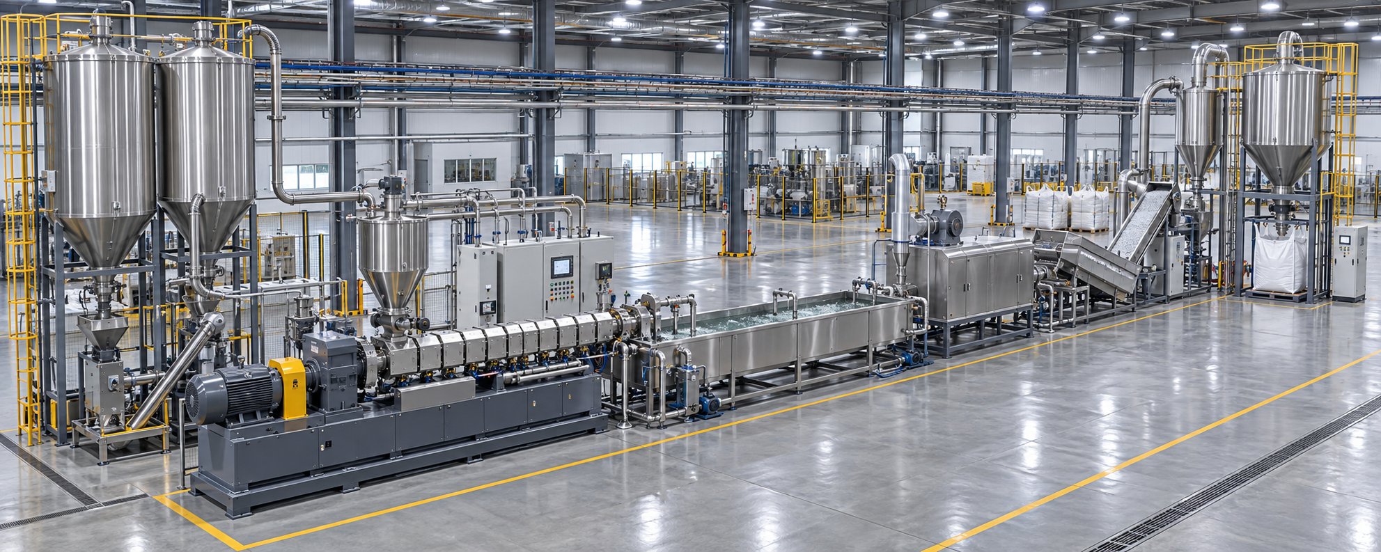
How to Build a Complete Twin Screw Pelletizing Production Line
A parallel twin screw extruder for pelletizing is the heart of the production line — but a heart without a circulatory system doesn't pump anything useful. The extruder cannot produce a single saleable pellet without properly engineered upstream preparation, downstream cooling, classification, and storage equipment working in concert. Yet engineers and purchasing managers routinely spec the extruder in exhaustive detail while treating everything else as an afterthought. The result? Bottlenecks that strangle throughput, quality problems that trace back to material preparation, and costly retrofits that could have been avoided with integrated planning from day one.
This section maps the complete twin screw pelletizing line equipment list — every stage from raw material intake to bagged pellets — and provides a practical decision-making framework for sizing each component to your specific application.
Upstream Equipment Integration
What happens before material enters the feed throat determines whether the extruder operates at its designed potential or spends half its time compensating for poorly prepared feedstock. Upstream equipment handles three essential functions: storing raw materials, conditioning them for processing, and delivering them to the extruder with the consistency and accuracy the formulation demands.
Drying systems are non-negotiable for hygroscopic polymers. Nylon, PET, polycarbonate, and ABS all absorb atmospheric moisture that triggers hydrolytic degradation during melt processing. A desiccant dryer or vacuum dryer positioned immediately upstream of the gravimetric feeder reduces moisture content to the 20-50 ppm range required for stable extrusion. Skip this step — or undersize the dryer — and no amount of vacuum venting inside the barrel can fully compensate. The molecular damage is done the instant wet polymer hits melting temperature.
Blending silos and pre-mixing systems ensure that formulation components arrive at the feed throat in the correct proportions. For simple two- or three-component blends, a tumble blender or ribbon mixer upstream of the feeder can pre-homogenize the dry mix before it enters the extruder. High-volume operations often use dedicated blending silos with integrated auger mixing, connected to the feeder via pneumatic or vacuum conveying lines.
Conveying systems — pneumatic, vacuum, or flexible screw conveyors — bridge the gap between raw material storage and the feed hopper. The critical design detail here is preventing material segregation and contamination during transport. Dense-phase pneumatic conveying preserves pellet integrity and prevents fines generation, while dilute-phase systems move higher volumes at the risk of pipe wear and particle attrition. For abrasive fillers like calcium carbonate or glass fiber, hardened conveying pipes and wear-resistant elbows extend maintenance intervals dramatically.
Each of these upstream components connects directly to the feeding section discussed earlier in this article. The gravimetric or volumetric feeder is the final upstream link — it receives conditioned, properly blended material from the preparation equipment and meters it into the extruder at a controlled, consistent rate. Any variability introduced upstream — inconsistent moisture levels, segregated blends, surging conveyor output — passes directly through the feeder and into the process.
Downstream Equipment from Die to Finished Pellet
Once the homogenized melt exits the die, a chain of downstream equipment for twin screw extruder pelletizing takes over. Each piece handles a specific post-extrusion task, and the sequence varies depending on the pelletizing method selected. Here is the complete line sequence from raw material intake to bagged pellets, presented as a single reference:
- Raw material receiving and storage — bulk silos, bag dumps, or octabin stations with inventory management
- Material conditioning — desiccant dryers for hygroscopic resins, dehumidifiers for storage areas, pre-blenders for multi-component formulations
- Conveying to extruder — pneumatic or vacuum conveying from storage to feed hopper, with metal detectors and magnet separators to protect the screws
- Feeding and metering — gravimetric or volumetric main feeder, side feeders for fillers and fibers, liquid injection pumps for additives
- Twin screw extrusion — melting, mixing, degassing, and pressure building through the modular barrel and screw configuration
- Melt filtration — screen changer (manual, hydraulic slide-plate, or continuous backflush) with 80-250 micrometer mesh to remove contaminants and gels
- Die and pelletizing head — strand die with guide rolls, underwater die plate, water ring cutter, or hot-face cutting assembly, matched to material and pellet specifications
- Cooling — water bath and air knife for strand pelletizing; tempered process water circulation loop for underwater systems; water ring chamber and dewatering screen for water ring pelletizers
- Pellet drying — centrifugal dryer or fluidized bed dryer to remove surface moisture, typically reducing residual water to below 0.05%
- Classification and quality control — vibrating screens (typically two-deck) to separate fines below 1 mm and oversized particles above the target range, plus optional pellet inspection cameras for color and shape verification
- Cooling and tempering — pellet cooling conveyors or counterflow coolers that bring pellet temperature down to safe storage levels, preventing clumping in silos
- Storage and packaging — storage silos with level sensors, connected to automated bagging stations, big-bag fillers, or bulk truck loading systems
A few components in this chain deserve closer attention because they are frequently undersized or overlooked.
Melt filtration sits between the extruder and the die, and its impact on pellet quality — and resale value — is enormous. A backflush filter at 80 micrometers can be the difference between commodity-grade and premium-grade pellets. For recycled polymer pelletizing, continuous backflush screen changers prevent the production interruptions that manual screen changes impose, maintaining both throughput and melt pressure stability at the die.
Pellet classification is the step most often skipped on budget-conscious lines — and it's the step that generates the most customer complaints. Fines (particles below 1 mm) jam hopper throats and create dust explosions risks. Oversized pellets and tails cause bridging in injection molding feed systems. A two-deck vibrating sieve costs a fraction of the extruder price but eliminates these downstream headaches entirely.
Centrifugal dryers for underwater and water ring systems must match the throughput of the pelletizer. An undersized dryer leaves residual surface moisture on the pellets, which causes clumping during storage, promotes mold growth in bags, and creates feeding problems for the customer. Drying capacity should be specified for your peak throughput rate, not your average — because pellet flow surges during process adjustments and startup.
Choosing the Right Components for Your Pelletizing Line
With so many equipment stages involved, how do you determine the right extruder size, feeding configuration, and pelletizing method for your specific situation? The decision framework follows four key variables — material type, production volume, mixing requirements, and pellet quality targets — applied in sequence.
Start with material type. Your polymer dictates the extruder screw geometry (co-rotating vs counter-rotating), the barrel metallurgy (standard nitrided vs bimetallic or coated), the upstream conditioning requirements (dryers for hygroscopic resins, compactors for film), and the pelletizing method (underwater for PET and engineering plastics, strand or water ring for polyolefins and masterbatch). Every other decision cascades from this starting point.
Size the extruder to your production volume. Choosing the right extruder size for pellet production means matching the machine's throughput range to your operational reality — not your best-case peak demand. A practical guideline from experienced line builders: target 70-80% of the extruder's rated capacity at your average production rate. This leaves headroom for feedstock variability, screen-change downtime, and future volume growth without pushing the machine into stress ranges that accelerate wear and shorten component life.
Match mixing intensity to formulation complexity. A simple remelting application — clean production scrap from a single resin — may require only a 28:1 to 32:1 L/D ratio with a basic kneading section. An aggressive multi-component compound with mineral fillers, fibers, and liquid additives needs 40:1 to 48:1 L/D, multiple side feeders, and extended dispersive and distributive mixing zones. Overspecifying mixing capacity wastes energy and can damage shear-sensitive materials; underspecifying leaves you with poorly dispersed pellets that fail quality checks.
Define pellet quality targets before selecting downstream equipment. Spherical pellets for automated injection molding systems demand underwater pelletizing. Cylindrical pellets for general-purpose compounding work fine with strand cutting at lower capital cost. Near-zero dust requirements push you toward die-face cutting methods (underwater or water ring) that cut in the molten state. High color-change frequency favors strand pelletizing for faster purge cycles. Every downstream component — cooler, dryer, classifier, silo — must then be sized to handle the output of the pelletizing method you've selected.
A pelletizing line is only as strong as its weakest component. Premium screw and barrel quality means nothing if the melt filter is undersized, the dryer cannot keep up, or the pellet classifier is missing entirely. Design the line as an integrated system, and spec every stage to match your most demanding production scenario.
This systems-level perspective also applies to component sourcing. The barrel and screw assembly — the highest-wear, highest-precision components in the line — directly governs mixing performance, energy efficiency, and maintenance intervals. Generic barrels designed for broad compatibility inevitably compromise performance in specific applications. Producers building or upgrading pelletizing lines for compounding, recycling, or masterbatch production benefit from partnering with suppliers who engineer barrel solutions around the exact polymer, filler system, and throughput requirements of the application. NANHAIYA's custom parallel twin screw barrels exemplify this approach — each barrel is designed for the specific mixing, conveying, and wear-resistance demands of the target application, whether that's abrasive mineral-filled compounds, corrosive PVC formulations, or high-throughput polyolefin recycling lines.
Building a pelletizing line that performs reliably at its rated capacity, produces consistently on-spec pellets, and runs with minimal unplanned downtime is ultimately an exercise in integration. The extruder is the centerpiece, but the feeding system, material conditioning, melt filtration, pelletizer, cooling, drying, classification, and storage equipment must all be sized, positioned, and controlled as a unified system. When every link in that chain is properly specified — from the barrel metallurgy inside the extruder to the vibrating screen at the end of the line — the result is a production asset that delivers maximum throughput, minimal waste, and pellet quality that keeps customers reordering.
Frequently Asked Questions About Parallel Twin Screw Extruders for Pelletizing
1. What makes a parallel twin screw extruder better than a single screw extruder for pelletizing?
A parallel twin screw extruder provides superior mixing through intermeshing, self-wiping screws that generate both dispersive and distributive forces — capabilities a single screw simply cannot replicate. While single screw machines work well for remelting pre-compounded resin, they lack the shear fields and elongational flows needed to break apart pigment agglomerates, uniformly distribute glass fibers, or blend immiscible polymer alloys in a single compounding-and-pelletizing step. Twin screw systems also offer modular screw configurations, multiple feed and venting ports, and narrow residence time distribution, all of which contribute to consistent pellet composition, fewer defects, and broader material flexibility across engineering plastics, masterbatch, filled compounds, and recycled streams.
2. How do I choose between co-rotating and counter-rotating twin screw extruders for pelletizing?
The choice depends primarily on the material you are processing. Co-rotating parallel twin screw extruders dominate most pelletizing applications — masterbatch, engineering plastics, filled compounds, and polymer alloys — because they deliver high-intensity mixing, excellent self-wiping action, and high throughput. Counter-rotating designs are preferred for thermally sensitive materials like PVC, where lower shear and a calendering-style mixing mechanism prevent degradation, discoloration, and acid gas release. If your production line handles multiple polymer families beyond PVC, a co-rotating configuration offers the broadest versatility and fastest changeovers.
3. What L/D ratio should I select for my twin screw pelletizing extruder?
理想的长径比 (L/D) 取决于配方的复杂程度。对于简单的重熔或添加剂极少的常规回收,24:1 至 32:1 通常就足够了。对于填料含量适中、采用一到两个捏合区并配备真空排气装置的标准混炼,通常需要 32:1 至 40:1。而对于复杂应用,例如多颜料母料、玻璃纤维增强工程塑料或需要多个注射点和两级真空排气的配方,则需要 40:1 至 48:1。长径比不足会导致混合区压缩、挥发分释放不完全以及颗粒质量不稳定,而长径比过高则会增加资本成本和能源消耗,却没有相应的收益。
4. 线状造粒和水下造粒有什么区别?
丝状造粒是将熔融聚合物以连续丝状挤出通过水浴,然后在固态下切割成圆柱形颗粒。它具有最低的初始投资成本、广泛的材料兼容性和快速换型等优点,是代工生产商和需要频繁更换产品的企业的理想选择。水下造粒则是在充满水的腔室内,直接在模面切割熔融聚合物,生产出粉尘极少、产量最高的球形颗粒——最高可达约70,000磅/小时。然而,水下造粒系统成本更高、机械结构更复杂,并且存在模头冻结的风险。最佳选择取决于您对颗粒形状的要求、产量、材料类型和预算。
5. 双螺杆造粒机中料筒和螺杆材料的选择有多重要?
料筒和螺杆材质的选择直接影响颗粒质量、维护周期和总体拥有成本。加工含40-80%磨蚀性矿物填料时,标准氮化料筒的使用寿命会缩短至仅2000-3000小时,而双金属或碳化钨涂层内衬则可将使用寿命延长两到三倍。腐蚀性配方(例如PVC)需要耐氯化物合金,而高温工程塑料则受益于耐腐蚀双金属内衬。像南海亚这样的供应商提供定制的平行双螺杆料筒(nhyscrews.com),这些料筒专为特定应用而设计,例如混炼、回收、造粒和母料生产,确保耐磨性、尺寸精度和冶金性能与每种聚合物和填料体系的精确要求相匹配。
Written by
Nanhaiya Technical Team
Zhoushan Nanhaiya Plastic Machinery Co., Ltd.
The Nanhaiya technical team supports screw and barrel manufacturing projects through application review, technical communication, custom manufacturing coordination, and production and quality control.
Discuss Your Application
Related Articles
More insights on screw barrel technology and plastics processing.

What Nobody Tells You About Screw Barrel For Plastic Machine Design
Oct 10, 2026
Learn how screw barrel for plastic machine design affects melt quality, throughput, and wear life. Covers geometry, resin matching, troubleshooting, and sourcing.
Read Article
Single Screw Extruder for Sheet: Stop Guessing, Start Specifying
Oct 9, 2026
Learn how to specify a single screw extruder for sheet production. Covers screw geometry, resin-specific processing, troubleshooting, and maintenance best practices.
Read Article
PE Pipe Extruder Machine: What Datasheets Won't Tell You
Oct 9, 2026
Learn how a PE pipe extruder machine works, key specs explained, material grade selection, maintenance tips, and buyer guidance beyond the datasheet.
Read ArticleLooking for something else?
Search by material, symptom or product and jump straight to the relevant page.
These are navigation suggestions based on keyword matching — not a quotation, not a delivery commitment, and not a substitute for engineering review. Final specification is confirmed by our engineers against your drawings and processed material.
Need help with screw barrel selection?
Share your machine model, processed material and application. Our team can help with pricing and technical support.