

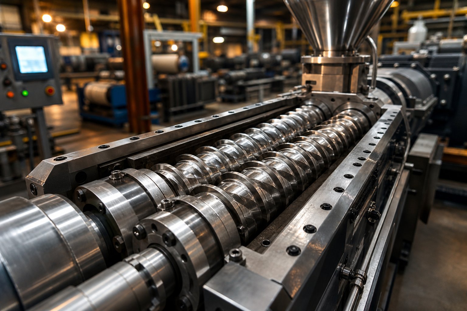
What Parallel Twin Screw Technology Is and Why It Dominates
Imagine two perfectly synchronized screws spinning side by side inside a heated barrel, grabbing raw plastic pellets at one end and delivering a fully melted, thoroughly mixed compound at the other. That, in its simplest form, is what a parallel twin screw extruder does—and it is the reason this machine sits at the heart of nearly every modern polymer compounding line worldwide.
Yet the technology is far more nuanced than that snapshot suggests. The geometry, the modular design philosophy, and the processing flexibility packed into these machines are what separate them from every other extrusion platform on the market. Understanding those fundamentals is the first step toward designing better screw configurations, optimizing throughput, and scaling formulations with confidence.
What Is a Parallel Twin Screw Extruder
A parallel twin screw extruder consists of two intermeshing screws mounted on parallel axes that rotate within a cylindrical barrel. Both screws share a constant outer diameter from the feed throat all the way to the discharge end. This constant-diameter architecture is the defining trait that distinguishes a parallel configuration from a conical one, where the screws taper from a larger diameter at the feed zone down to a smaller diameter at the tip.
A parallel twin screw extruder is a continuous processing machine featuring two equal-diameter, intermeshing screws on parallel center axes that convey, melt, mix, and pressurize material through coordinated screw rotation within a modular, temperature-controlled barrel.
When raw material enters the feed section, the rotating screw flights grip and push it forward. As the material advances along the barrel, it encounters progressively higher temperatures and shear forces generated by the intermeshing flight geometry. These forces melt the polymer matrix, disperse additives and fillers uniformly, and build the pressure needed to push the finished melt through a die or into a pelletizing system.
The significance of a constant channel depth along the entire barrel length cannot be overstated. Unlike tapered designs—where channel volume shrinks toward the discharge—a twin screw extruder with uniform diameter offers predictable, repeatable processing behavior at every position along the shaft. This consistency makes it far easier to model material flow, control residence time, and troubleshoot quality deviations.
Why Parallel Geometry Matters for Processing
So why has this particular geometry become the dominant platform for compounding, masterbatch production, and reactive extrusion? The answer centers on three engineering advantages that no competing architecture can match simultaneously.
First, uniform screw diameter enables truly modular screw element assembly. Because the shaft spline profile and outer diameter remain constant, individual conveying elements, kneading blocks, and mixing elements can be placed at any position along the screw. Practitioners rearrange these elements on splined shafts to tailor the machine for each specific formulation—no new screws required, just a different sequence of building blocks.
Second, consistent free volume along the barrel length gives processors reliable control over fill level and specific energy input. You know exactly how much volumetric capacity is available in every zone, which simplifies feed rate calculations and venting strategies.
Third, the intermeshing flight geometry delivers a narrow, predictable residence time distribution. Material spends a well-defined amount of time inside the barrel, reducing the risk of thermal degradation for heat-sensitive polymers and ensuring that every particle receives a similar mixing history. This level of control is precisely why twin screw extruders handle everything from glass-fiber-reinforced engineering plastics to sensitive bio-based polymers with equal confidence.
These three pillars—modularity, volumetric consistency, and residence time control—are what propelled parallel twin screw technology from a niche compounding tool into the global standard. The real depth of its engineering, however, lies in the geometric ratios and intermeshing mechanics that make all of this possible.
Engineering Principles Behind Parallel Twin Screw Design
Every parallel twin screw extruder is defined by a handful of geometric relationships that dictate how much material the machine can process, how intensely it mixes, and how much torque the drive can safely deliver. Strip away the brand names and control panels, and you are left with three critical dimensions: the outer screw diameter (Do), the inner or root diameter (Di), and the centerline distance between the two shafts. These values are fixed for any given machine size, and their ratios shape virtually every performance characteristic an operator will encounter on the factory floor.
Understanding these relationships is not just an academic exercise. When you select a screw extruder for a new formulation, the Do/Di ratio tells you whether the machine favors high throughput or high torque—two goals that often compete with each other. Getting this decision right at the specification stage saves months of troubleshooting later.
Understanding Do/Di Ratio and Free Volume
The Do/Di ratio—sometimes expressed as its inverse, Di/Do—is the single most important geometric descriptor for any extruder twin screw platform. It compares the outer flight diameter to the root diameter of the screw. Industry designs typically fall within a Do/Di range of roughly 1.22 to 1.71, and the position within that range creates a fundamental trade-off between two competing priorities.
A higher Do/Di ratio means deeper screw channels. Deeper channels translate directly into greater free volume—the open space inside the barrel available for material transport and processing. More free volume allows higher throughput capacity, improved intake of low-bulk-density powders, and more generous venting capability. If you are processing lightweight fillers or running devolatilization-heavy recipes, a deeper-channel geometry gives you room to breathe.
There is a catch, though. Deeper channels leave less cross-sectional area for the torque-carrying shaft. The shaft must fit inside that smaller root diameter, which limits its mechanical strength and the maximum torque the drive system can transmit. In practice, this means that machines with a high Do/Di ratio can move a lot of material, but they may struggle with high-viscosity melts or heavily filled compounds that demand significant mechanical energy input.
Flip the ratio toward the shallow-channel end—closer to 1.22—and the opposite holds true. The shaft occupies a larger proportion of the screw cross-section, delivering higher torque density. Twin screws built on this geometry excel at energy-intensive compounding tasks, such as processing engineering thermoplastics, where the extruder's torque limit is often the bottleneck. The trade-off is reduced free volume and, consequently, lower volumetric throughput capacity.
Real-world selection often comes down to the processing energy your material demands. As Xtrutech's geometry analysis illustrates, powder coatings require only about 0.04 to 0.08 kWh/kg of specific energy—well below the torque ceiling of modern machines—meaning a high-free-volume geometry (Do/Di around 1.8) makes sense because intake and venting are the real constraints. Engineering thermoplastics, by contrast, can demand more than three times that energy input, pushing operators toward a shallower-channel design that maximizes available shaft torque.
One subtle but powerful consequence of maintaining a constant Do/Di ratio along the entire barrel length is full modularity. Because every axial position shares the same cross-sectional geometry, individual screw elements—conveying flights, kneading blocks, mixing discs—can be placed anywhere along the splined shaft without geometric conflict. This is the engineering foundation that makes screw extrusion on a parallel platform so remarkably flexible compared to tapered alternatives.
Intermeshing Geometry and Self-Wiping Behavior
Picture two gears meshing together, but instead of rigid teeth, imagine helical flights that interlock along their entire length. In a co-rotating parallel twin screw extruder, the flight tip of one screw sweeps continuously through the channel of the adjacent screw. This action—known as self-wiping—is one of the most important functional characteristics separating intermeshing twin screws from single-screw machines or non-intermeshing designs.
Self-wiping geometry accomplishes three things simultaneously. First, it creates positive conveying action. Material cannot simply sit idle in the channel; the approaching flight of the neighboring screw pushes it forward, ensuring reliable transport even under starve-fed conditions. Second, the wiping motion virtually eliminates dead zones—stagnant pockets where polymer can overheat, degrade, or crosslink. This is critical for heat-sensitive materials, where even a few seconds of excessive residence time can ruin product quality.
Third, self-wiping behavior produces a narrow residence time distribution (RTD). Research on intermeshing co-rotating parallel screw systems has consistently shown that this geometry delivers one of the tightest RTD profiles of any continuous processing platform. A study published in Polymers (2022) confirmed that self-wiping parallel screw configurations maintain well-defined residence times closely tied to screw speed and feed rate, which allows processors to predict thermal exposure with high accuracy.
Why does narrow RTD matter in practice? Consider reactive extrusion, where a chemical reaction must reach a target conversion level without overshooting. If some material lingers too long inside the barrel while other portions pass through quickly, you end up with an inconsistent product—partially reacted in some regions, over-reacted in others. The tight RTD enabled by intermeshing self-wiping geometry solves this problem by ensuring every particle experiences a nearly identical thermal and mechanical history.
The interplay between Do/Di ratio and intermeshing behavior also influences shear rate distribution. In a fully filled channel, deeper-channel geometries (higher Do/Di) produce a lower average shear rate at a given screw speed. Xtrutech's technical analysis offers a useful rule of thumb: the shear rate at 300 RPM on a Do/Di = 1.55 extruder is roughly equivalent to the shear rate on a Do/Di = 1.8 machine operating at 500 RPM. This relationship gives formulators an additional tuning lever—adjusting geometry selection to match the shear sensitivity window of their specific material system.
To put these engineering principles in sharper context, it helps to see how the parallel configuration stacks up against the main alternative—conical twin screw designs—across the geometric parameters that matter most.
| Geometric Parameter | Parallel Twin Screw | Conical Twin Screw |
|---|---|---|
| Screw Diameter | Constant (equal Do from feed to discharge) | Tapered (larger at feed, smaller at discharge) |
| Channel Depth | Uniform along barrel length; defined by Do/Di ratio | Decreases toward discharge end as screw tapers |
| Barrel Bore Shape | Two parallel cylindrical bores of equal diameter | Two converging conical bores |
| Do/Di Ratio Flexibility | Wide range available (typically 1.22–1.71) | Fixed by taper angle; limited selection |
| Modular Screw Elements | Fully modular—elements interchangeable at any shaft position | Not modular; screws are typically one-piece designs |
| Free Volume Distribution | Consistent along entire length | Higher at feed end, lower at discharge |
| Typical Application Focus | Compounding, masterbatch, reactive extrusion, recycling | PVC pipe and profile extrusion |
The comparison makes one point especially clear: the constant-diameter architecture of a parallel design is what unlocks full modularity and volumetric consistency—two features that conical machines, by the nature of their taper, cannot replicate. Conical extruders do offer advantages in certain niches, particularly PVC processing where their natural pressure build-up profile and large feed-zone intake area align well with the material's requirements. But for applications demanding flexible screw configurations and frequent recipe changes, the parallel platform remains unmatched.
Geometry alone, however, only tells half the story. The real versatility of a parallel twin screw system emerges when you consider the directional relationship between the two screws—whether they rotate in the same direction or in opposite directions—and how that choice reshapes material flow, shear intensity, and application suitability.
Co-Rotating vs Counter-Rotating Parallel Twin Screw Configurations
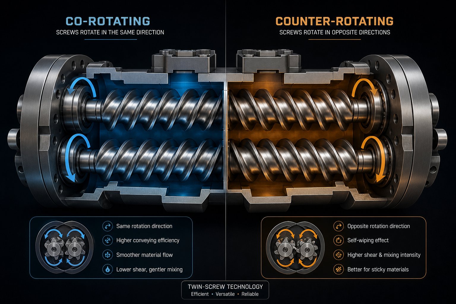
Two screws, identical diameters, shared barrel—but spin them in different directions and you get radically different processing behavior. This single design decision—co-rotating or counter-rotating—determines shear intensity, material flow path, maximum operating speed, and ultimately which applications a double screw extruder can handle well. Choosing between a co rotating twin screw extruder and its counter-rotating counterpart is arguably the most consequential specification choice any processor makes, yet it is often reduced to a one-line footnote in equipment catalogs.
Here is the full picture.
Co-Rotating Intermeshing Configuration
In a co rotating twin screw extruder, both screws turn in the same direction—typically with fully intermeshing geometry. Imagine tracing the path a polymer pellet takes: it enters one screw channel, gets handed off to the neighboring screw at the intermeshing zone, travels along that screw's flight, then crosses back again. The result is a distinctive figure-eight flow pattern that forces material through repeated high-shear and reorientation events.
This continuous hand-off creates powerful self-wiping action. The flight tip of one screw sweeps the channel of the other, preventing stagnation and ensuring virtually no dead zones exist inside the barrel. For heat-sensitive polymers or reactive extrusion processes where even brief stagnation causes degradation, this characteristic is indispensable.
Modern co-rotating machines operate at impressive speeds—some exceeding 1200 RPM—which translates to intense distributive and dispersive mixing simultaneously. High rotational speed combined with the figure-eight flow delivers exceptional filler dispersion, polymer alloy morphology control, and rapid melting. These attributes explain why co-rotating configurations dominate the global compounding market, handling everything from nanocomposites to glass-fiber-reinforced engineering plastics.
Counter-Rotating Intermeshing Configuration
Flip the rotation direction of one screw, and the processing physics change fundamentally. In a counter-rotating intermeshing machine, material is drawn inward at the nip point between the screws—similar to how a two-roll calender pulls sheet material through its gap. This calendering effect generates compressive and elongational deformation rather than the high-shear fields typical of co-rotating designs.
The result? Lower shear stress, reduced shear-induced heat generation, and a more positive displacement pumping action. Material transport depends heavily on screw rotation itself rather than drag flow, which means stable extrusion is achievable at comparatively low RPM and high fill levels.
These characteristics make counter-rotating configurations ideal for pressure-sensitive and thermally unstable materials. Rigid PVC—notorious for its narrow processing window and tendency to degrade under excessive shear—is the classic example. Counter-rotating machines hold melt temperature low while still achieving adequate mixing through the calendering mechanism, enabling stable production of PVC pipes, profiles, and sheets. Where a co rotating and counter rotating twin screw extruder might seem interchangeable at first glance, the shear and thermal profiles are worlds apart.
Non-Intermeshing Variants and Their Niche Uses
Beyond the mainstream intermeshing designs, non-intermeshing configurations occupy specialized niches. In these machines, the screws rotate in close proximity but their flights do not engage each other. Without intermeshing, there is no self-wiping action and no positive conveying—material transport relies primarily on friction and drag.
Co-rotating non-intermeshing designs find use in devolatilization applications where large free surface area matters more than mixing intensity. Counter-rotating non-intermeshing variants serve as continuous chemical reactors, where gentle handling and extended residence time are priorities over throughput. Neither configuration rivals the mixing efficiency of intermeshing designs, but for their targeted applications, the trade-off is worthwhile.
Unlike a conical twin screw extruder—which uses tapering screws and typically operates only in counter-rotating intermeshing mode for PVC processing—the parallel platform supports all four rotational and meshing combinations. This versatility is a key reason parallel geometry dominates across such a wide application landscape.
| Parameter | Co-Rotating Intermeshing | Counter-Rotating Intermeshing | Co-Rotating Non-Intermeshing | Counter-Rotating Non-Intermeshing |
|---|---|---|---|---|
| Mixing Efficiency | Excellent (dispersive + distributive) | Moderate (calendering-based dispersion) | Low to moderate | Low |
| Shear Rate Range | High (adjustable via RPM and elements) | Low to moderate | Low to moderate | Low |
| Self-Wiping Capability | Full self-wiping | Partial (geometry-dependent) | None | None |
| Typical Speed Range | 200–1200+ RPM | 10–150 RPM | 100–400 RPM | 50–200 RPM |
| Conveying Mechanism | Drag flow + positive displacement | Positive displacement dominant | Drag and friction | Friction dominant |
| Primary Applications | Compounding, masterbatch, reactive extrusion, recycling | PVC extrusion, pressure-sensitive compounds | Devolatilization, surface renewal | Continuous chemical reactors, specialty polymers |
The table reveals a pattern worth internalizing: as you move from co-rotating intermeshing toward non-intermeshing designs, you trade mixing intensity and speed for gentleness and residence time control. No single configuration is universally superior—the right choice depends entirely on what your material demands and what your process must achieve.
Yet selecting the right rotational mode is only the first layer of customization. The real precision in parallel twin screw processing comes from what sits on those shafts—the individual screw elements whose sequence and selection create distinct processing zones capable of handling virtually any compounding challenge.
Modular Screw Element Design and Configuration Strategy
Picture a toolkit where each piece snaps onto a common shaft, and the order you stack them in completely redefines what the machine does. That is the reality of twin screw extrusion on a parallel platform. Rather than machining a monolithic screw for each application, processors assemble individual elements onto a splined shaft—each element performing a specific function at a specific position along the barrel. Swap the sequence, change the outcome.
This modular philosophy is why twin screw extruders handle such wildly different tasks on identical hardware. A compounding line running calcium carbonate at 60% loading uses a fundamentally different element arrangement than one processing a reactive polymer blend—yet both share the same barrel, drive, and shaft spline geometry. The magic lies in how you choose and sequence three families of screw elements: conveying elements, kneading blocks, and specialty mixing elements.
Conveying Elements and Their Functions
Conveying elements are the workhorses of material transport. They look like traditional helical flights and do exactly what their name suggests—move material forward through the barrel. But their pitch angle determines far more than just speed.
A large-pitch conveying element—think of a loosely wound spring—grabs high volumes of material and moves them quickly. This makes large-pitch elements ideal for the feed zone, where bulk density is low and you need aggressive intake. As NC State Extension's screw design guide notes, conveying ability decreases with decreasing pitch, so tighter-pitch elements downstream compress the material, increase fill level, and begin building pressure toward the die.
Then there are reverse-pitch elements—conveying flights wound in the opposite direction. These push material backward, creating a restrictive dam that forces the upstream zone to fill completely. Why would you deliberately slow material down? Because a fully filled zone upstream of a reverse element ensures consistent pressure for venting, guarantees complete kneading block engagement, and creates melt seals that isolate barrel zones from each other. Reverse elements are short by design—typically less than one screw diameter in length—to avoid extreme pressure peaks and excessive mechanical stress.
Kneading Blocks for Dispersive and Distributive Mixing
If conveying elements handle transport, kneading blocks handle transformation. These elements consist of multiple disc-shaped lobes stacked at offset angles along the shaft. Three variables control their behavior: disc width, stagger angle, and conveying direction.
Disc width determines the type of mixing. Narrow kneading discs generate frequent, abrupt changes in flow pattern over short axial distances. According to CPM's engineering guide on twin-screw extruder screw design, this intensifies local shear and pressure gradients—exactly what you need for dispersive mixing that fractures agglomerates of pigments, fillers, or nanoparticles. Wide kneading discs, by contrast, produce smoother flow transitions and excel at distributive mixing—spreading components evenly throughout the melt without necessarily applying destructive force.
Stagger angle is your intensity dial. At a 30-degree offset between adjacent discs, material advances through the block with only moderate shear—good for gentle blending. Increase to 60 degrees, and you substantially boost shear intensity while reducing forward conveying. At 90 degrees (neutral stagger), the kneading block provides zero forward transport—material simply churns in place, experiencing maximum residence time and the highest shear stress. Reverse-staggered kneading blocks push material backward, much like reverse conveying elements, creating even more aggressive mixing conditions.
The practical takeaway? You can shift from primarily distributive to intensely dispersive mixing simply by narrowing disc width, lengthening the kneading section, and increasing stagger angle. Each adjustment trades gentleness for intensity—and raises melt temperature accordingly. Twin-screw extruders give practitioners this fine-grained control because every element can be repositioned independently on the splined shaft.
Specialty Elements for Advanced Processing
Beyond standard conveying flights and kneading blocks, a third family of elements addresses processing challenges that neither of the first two can solve alone.
- Toothed mixing elements (TME): Feature rows of protruding teeth that split and recombine flow streams with minimal shear stress. Ideal for distributive mixing of heat-sensitive materials or for blending liquid additives into a melt without excessive temperature rise.
- Gear mixing elements (GME): Create elongational flow fields by forcing material through alternating channels. Elongational stress is more efficient at breaking certain agglomerates than shear alone, making these elements valuable for nano-filler dispersion.
- Screw mixing elements (SME): Combine forward conveying with interrupted flights that generate cross-channel flow. They offer a middle ground—more mixing than a standard conveying element, less intensity than a kneading block.
- Distributive mixing tips: Placed at the screw discharge end to homogenize the melt one final time before it enters the die, ensuring uniform temperature and composition across the strand cross-section.
Sounds complex? It is—but the logic is consistent. Each element type addresses a specific material transformation requirement, and the practitioner's job is to sequence them into coherent processing zones.
A typical screw profile for a compounding twinscrew operation follows a recognizable pattern: large-pitch conveying elements in the feed zone to intake material; a transition to tighter pitch for the melting zone, often paired with forward kneading blocks to initiate shear-driven melting; aggressive kneading sections in the mixing zone to disperse additives; conveying elements with low fill at vent ports for the venting zone; and finally, tight-pitch conveying or metering elements to build die pressure in the metering zone. Reverse elements or neutral kneading blocks punctuate transitions between zones, acting as seals that isolate pressure and fill conditions.
This zone-based design thinking is what transforms a generic twin screw extruders platform into a precision processing tool. And when the element configuration is dialed in for a particular formulation, the next question becomes obvious: what real-world applications push these capabilities to their limits—and where does this modular flexibility deliver the greatest return?
Applications Where Parallel Twin Screw Extruders Excel
A modular screw profile only matters if the application demands that level of configurability. And in practice, it does—across a remarkably broad range of industries. The parallel twin screw platform is not a specialist tool reserved for one niche. It is the universal workhorse for any process where mixing intensity, throughput consistency, and formulation flexibility must coexist. From blending commodity resins with mineral fillers to running complex chemical reactions in the melt state, these machines adapt through element selection, barrel configuration, and process parameter control.
What follows is a breakdown of the major application sectors—not just listing what processors make, but explaining why the parallel geometry is technically suited to each task in a way no alternative can replicate.
Compounding and Masterbatch Production
Polymer compounding is the bread and butter of the twin screw compounding extruder. The job sounds straightforward—blend a base polymer with additives, fillers, pigments, or reinforcements to produce a compound with enhanced properties. In reality, it is one of the most demanding continuous processing tasks in the plastics industry.
Consider what happens when you feed polypropylene pellets alongside 40% talc powder and a package of stabilizers, coupling agents, and lubricants. The extruder must melt the polymer matrix rapidly, wet out every talc particle, break apart agglomerates without fracturing individual platelets, distribute all additive components uniformly, and discharge a homogeneous melt—at throughputs exceeding several tons per hour on production machines. Any dead zones or inconsistent shear history produces speckled parts, weak weld lines, or off-spec mechanical performance downstream.
A compounding extruder built on parallel twin screw architecture handles this challenge because of the self-wiping intermeshing geometry combined with configurable kneading zones. Torontech's engineering reference confirms that the intermeshing action generates high shear forces that break down pellets and ensure thorough dispersion of additives or fillers, producing a homogeneous melt suitable for downstream pelletizing. You dial in dispersive mixing intensity where agglomerates need breaking, then transition to distributive mixing where gentle homogenization preserves filler morphology. One machine, one screw profile, one pass.
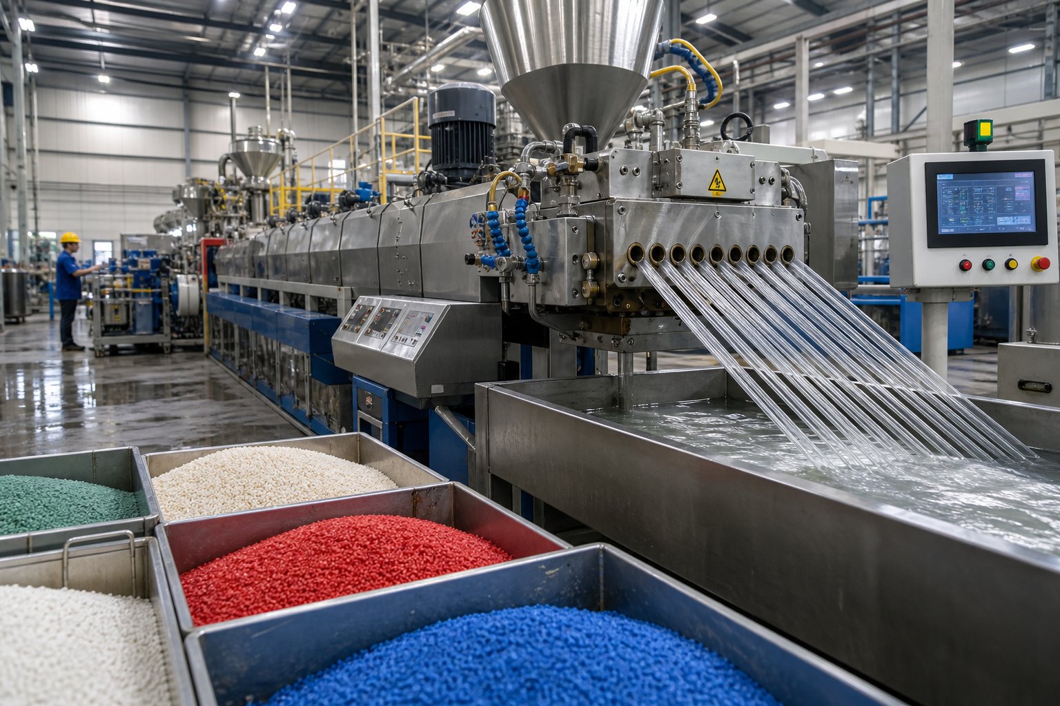
Masterbatch production pushes the same platform even harder. A color masterbatch might contain 40–70% pigment by weight in a carrier resin—concentrations that would choke a single-screw machine. The compounding twin screw extruder manages this because its modular kneading sections deliver enough shear to fully wet out and disperse pigment particles, while its positive conveying action ensures material keeps moving forward despite the extreme viscosity and high filler loading. After discharge, a screw extruder granulator downstream cuts the strand into uniform pellets ready for letdown into natural resin at the injection molder's end.
Reactive Extrusion and Devolatilization
When you need to run a chemical reaction inside an extruder—grafting functional groups, polymerizing monomers, or controlled degradation of polymer chains—the process is called reactive extrusion (REX). And it demands something that batch reactors struggle to deliver: precise control over residence time, temperature history, and mixing intensity, all in a continuous flow.
Parallel twin screw systems are uniquely suited for REX because their narrow residence time distribution ensures every molecule experiences nearly identical thermal and mechanical conditions. Research published in JACS Au (2026) highlights that corotating twin-screw extruders outperform single-screw and counter-rotating counterparts for reactive melt extrusion by offering larger capacity and better heat distribution. The modular barrel design allows precise placement of liquid injection ports, mixing zones, and vacuum vents—each positioned to match the reaction kinetics of the specific chemistry involved.
A typical example is maleic anhydride grafting onto polypropylene. As Plastics Technology's deep dive on REX explains, a peroxide initiator creates radical sites on the polyolefin backbone, onto which the maleic anhydride monomer grafts. The screw configuration plays a significant role in how intimately the reactive species mix with each other—ensuring homogeneous distribution and dispersion of the different chemical species within the polyolefin melt. Too little mixing and grafting efficiency drops; too much residence time and chain scission degrades the polymer. The modular twin screw plastic extruder lets practitioners tune this balance zone by zone.
Devolatilization—the removal of moisture, residual monomers, solvents, or reaction byproducts from a polymer melt—exploits a different feature of the parallel platform: open barrel vents under vacuum. By placing conveying elements with a forward-pumping pitch at vent ports, the melt forms a thin, partially filled layer with high surface area. Vacuum applied at these open barrel sections strips volatiles efficiently. Multiple vent zones can be arranged in series, each preceded by melt seals created by reverse elements, allowing staged removal of different volatile fractions. IUPAC recognized reactive melt extrusion as one of its top ten emerging sustainable technologies precisely because this solvent-free approach aligns with green chemistry principles—minimizing waste, avoiding solvents, and reducing energy consumption.
Recycling, Filled Polymers, and Emerging Applications
Recycling operations present a unique challenge: feedstock variability. Post-consumer plastic waste arrives with mixed polymers, fluctuating moisture content, residual labels and adhesives, and unpredictable contamination levels. A single-screw extruder chokes on this inconsistency. A parallel twin screw system thrives on it—because the robust self-wiping action prevents buildup of contaminants on barrel walls, multiple vent zones strip moisture and volatiles, and configurable kneading intensity handles viscosity variations from batch to batch.
Highly filled compounds represent another strength area. Calcium carbonate loadings above 80%, glass fiber concentrations of 30–50%, talc-filled polypropylene for automotive parts—each demands careful balancing of dispersive energy (enough to wet and distribute the filler) against mechanical damage (too much shear fractures glass fibers, reducing their reinforcing efficiency). The zone-based screw design philosophy enables exactly this: aggressive kneading where dispersion is needed, gentle conveying where fiber length must be preserved.
Emerging applications are pushing the platform into entirely new territory. Bio-based polymer processing—polylactic acid (PLA), polyhydroxyalkanoates (PHA), and starch-based blends—requires careful thermal management and moisture removal that parallel machines handle through their multiple independent temperature zones and vent ports. Continuous pharmaceutical manufacturing uses small-diameter twin screw systems for hot-melt extrusion of drug delivery formulations, where precise temperature control and efficient mixing ensure uniform distribution of active ingredients within a polymer carrier matrix.
Ranked by global market adoption, the top application sectors for parallel twin screw technology reflect this diversity:
- Polymer compounding and masterbatch production — the largest single segment, driven by continuous demand for filled, reinforced, and color-concentrated compounds across automotive, packaging, and consumer goods industries.
- Recycling and reprocessing — growing rapidly as regulatory pressure and circular economy initiatives push processors toward post-consumer and post-industrial waste streams.
- Reactive extrusion and functionalization — essential for producing compatibilizers, grafted polymers, and specialty materials that serve as performance enablers in downstream applications.
- Devolatilization and solvent removal — critical for resin producers and compounders handling hygroscopic materials, residual monomers, or water-based slurries.
- Food, pharmaceutical, and bio-based polymer processing — the fastest-growing emerging segment, leveraging the same modular, continuous, precisely controlled platform for non-traditional materials.
Across every one of these sectors, the underlying technical justification remains the same: modular screw design enables application-specific optimization, self-wiping geometry prevents degradation and ensures consistency, and continuous operation delivers the throughput economics that batch processes cannot match.
Matching the right application to the right screw configuration, however, is only half the operational equation. Even a perfectly designed screw profile underperforms if the process parameters—speed, feed rate, temperature—are not tuned to work in harmony with that configuration and the specific material flowing through the barrel.
Process Optimization and Troubleshooting for Parallel Twin Screw Systems
A perfectly configured screw profile sitting inside a well-engineered barrel still produces off-spec material if the process parameters fighting each other. Screw speed, feed rate, and barrel temperature are not independent dials you can twist in isolation—they form a tightly coupled network where adjusting one variable inevitably shifts the equilibrium of the others. Understanding this interdependence is what separates an experienced operator from someone just following a recipe card.
For anyone running a twin screw extruder machine day after day, the real skill is not memorizing setpoints. It is knowing which parameter to move first when something drifts, and predicting what will happen downstream when you do.
How Screw Speed, Feed Rate, and Temperature Interact
Think of these three parameters as the corners of a triangle. Pull one corner and the entire shape distorts.
Screw speed controls shear rate and residence time simultaneously. Increase RPM on a twin-screw extruder machine and you intensify the mechanical energy input in every kneading zone—raising melt temperature through viscous dissipation. At the same time, higher speed moves material through the barrel faster, reducing residence time. For heat-sensitive formulations, that shorter exposure window can be beneficial. But if your mixing zones need a certain minimum dwell time to achieve full dispersion, simply cranking speed may produce a hotter melt that is paradoxically less well-mixed.
Process parameter research from Thermo Fisher Scientific confirms that screw speed and feed rate have the greatest impact on melt temperature, with higher speeds delivering more mechanical energy in mixing zones. Interestingly, screw speed has a relatively small influence on residence time compared to feed rate—a counterintuitive insight that catches many operators off guard.
Feed rate determines the degree of fill inside the barrel. In a starve-fed double screw extruder machine—the standard operating mode for co-rotating systems—increasing throughput raises fill level, which increases the material volume engaged by kneading elements, boosting both shear heat generation and pressure buildup. A higher throughput also reduces average residence time and narrows the residence time distribution, as confirmed by the same Thermo Fisher research. The practical consequence? Pushing more material through the machine dilutes the specific energy each kilogram receives. If your formulation needs a certain energy input for full melting and dispersion, raising feed rate without a corresponding speed increase may produce under-mixed output.
Barrel temperature profile is often misunderstood as the primary heat source. In reality, for most thermoplastic compounding on a twin screw extruder plastic line, shear-generated heat accounts for 70% to 85% of total thermal energy input. Barrel heaters primarily serve to fine-tune thermal balance—establishing zonal temperature gradients, controlling melting onset in the feed section, and preventing overcooling or overheating at specific barrel positions. The barrel temperature you set on the controller is the steel temperature, which can deviate from actual melt temperature by 10 to 30 degrees Celsius under normal conditions.
The practitioner's challenge is balancing all three parameters to hit a target melt temperature window—hot enough for complete melting and adequate flow, cool enough to avoid degradation. Raise screw speed to improve mixing, and melt temperature climbs; compensate by increasing feed rate to dilute specific energy, and residence time drops; lower barrel temperature to pull heat out, and you risk incomplete melting in upstream zones. Every adjustment cascades.
Troubleshooting Common Process Issues
When something goes wrong on a parallel twin screw line, the symptom you see at the die is often two or three cause-and-effect steps removed from the actual root problem. A systematic approach—checking the most common culprits first—saves hours of trial-and-error adjustment.
The table below maps the most frequent production symptoms to their likely causes and the corrective actions that experienced operators reach for first.
| Symptom | Likely Cause | Corrective Action |
|---|---|---|
| Torque overload / drive trip | Excessive fill level from feed rate too high relative to screw speed | Reduce feed rate or increase screw speed; verify feeder calibration |
| Torque overload / drive trip | Barrel temperature too low in melting zone, forcing the screw to do all thermal work mechanically | Raise upstream barrel temperatures to assist melting onset |
| Torque overload / drive trip | Incorrect screw design—too many restrictive elements or excessive reverse-pitch length | Shorten reverse elements or reduce kneading block stagger angles |
| Surging or pulsating output | Inconsistent feeding from bridging, rat-holing, or feeder calibration drift | Inspect hopper flow; switch to loss-in-weight feeder; verify bulk density consistency |
| Surging or pulsating output | Vent flooding—material pushed out of open vent ports due to excessive fill in venting zone | Reduce feed rate; add or lengthen melt seal element upstream of vent; check vacuum level |
| Surging or pulsating output | Worn screw elements or barrel bore causing leakage flow and pressure instability | Measure bore diameter; inspect flight land wear; replace worn elements |
| Poor mixing or undispersed agglomerates | Insufficient kneading—too few kneading blocks or wrong stagger angle selection | Add kneading block length; increase stagger angle from 30 to 60 degrees; narrow disc width for dispersive action |
| Poor mixing or undispersed agglomerates | Excessive throughput relative to mixing capacity—material passes through kneading zones too quickly | Reduce feed rate or increase screw speed to extend effective mixing time |
| Poor mixing or undispersed agglomerates | Low fill level in mixing zones preventing full engagement with kneading elements | Add restrictive elements downstream of kneading section to raise local fill level |
| Elevated melt temperature / degradation | Screw speed too high for the given throughput, delivering excessive specific energy | Reduce RPM or increase feed rate to dilute energy input per kilogram |
| Elevated melt temperature / degradation | Barrel cooling insufficient—cooling water flow restricted or blowers malfunctioning | Inspect cooling circuits; descale water jackets; verify blower operation |
Notice a pattern? Most issues trace back to the relationship between fill level, energy input, and screw configuration—the same coupled triangle discussed above. The systematic troubleshooting methodology recommended for twin screw operations follows a consistent logic: gather data first, verify process parameters against known good settings, isolate the problem to a specific zone, then implement corrections and validate.
Energy Efficiency and Throughput Optimization
Every kilogram of compound your twin screw extruder plastic line produces absorbs a measurable amount of energy—and most of it comes from the drive motor, not the heaters. This quantity is called Specific Energy Input (SEI), expressed as kilowatt-hours per kilogram (kWh/kg). It is the single most useful metric for comparing process efficiency across different machine sizes, formulations, and operating conditions.
SEI tells you how hard the machine is working per unit of output. A high SEI means more energy per kilogram—sometimes necessary for demanding dispersive mixing, but often a sign of inefficiency if the same product quality could be achieved at lower intensity. A low SEI suggests gentle processing, which conserves energy and minimizes thermal load on the polymer, but may indicate insufficient mixing if product quality suffers.
Optimizing energy efficiency on a double screw extruder machine involves three levers working in concert:
- Screw design optimization: Replace overly aggressive kneading blocks with more efficient mixing elements—such as toothed or gear mixing elements—that achieve equivalent dispersion at lower shear stress and therefore lower energy dissipation.
- Feed rate maximization: Running the extruder closer to its volumetric capacity dilutes the fixed energy overhead (motor idle losses, barrel heating) across more kilograms of product, reducing SEI without sacrificing quality—provided mixing remains adequate.
- Speed-to-throughput ratio tuning: The ratio of screw speed to feed rate determines how much mechanical energy each kilogram receives. Lowering this ratio—by increasing throughput at constant speed, or reducing speed at constant throughput—drops SEI directly. The limit is the minimum mixing quality your formulation requires.
The coupled parameter framework for extrusion optimization reinforces this point: the seven key process parameters are never isolated variables but an interconnected network revolving around energy and mass flow. Truly efficient process optimization is not about finding a perfect setting for each parameter in isolation—it is about achieving the right balance across residence time, fill degree, shear heat, and mixing quality simultaneously.
One often-overlooked factor in this equation is equipment condition. Worn barrel bores and eroded screw flights increase leakage flow, forcing higher speeds to maintain throughput—which inflates SEI, raises melt temperature, and accelerates further wear in a destructive feedback loop. Recognizing the mechanical condition of your barrel and screws is not just a maintenance concern; it is a process optimization variable that directly impacts energy consumption and product consistency.
Barrel Wear Mechanisms and Metallurgy for Long Service Life
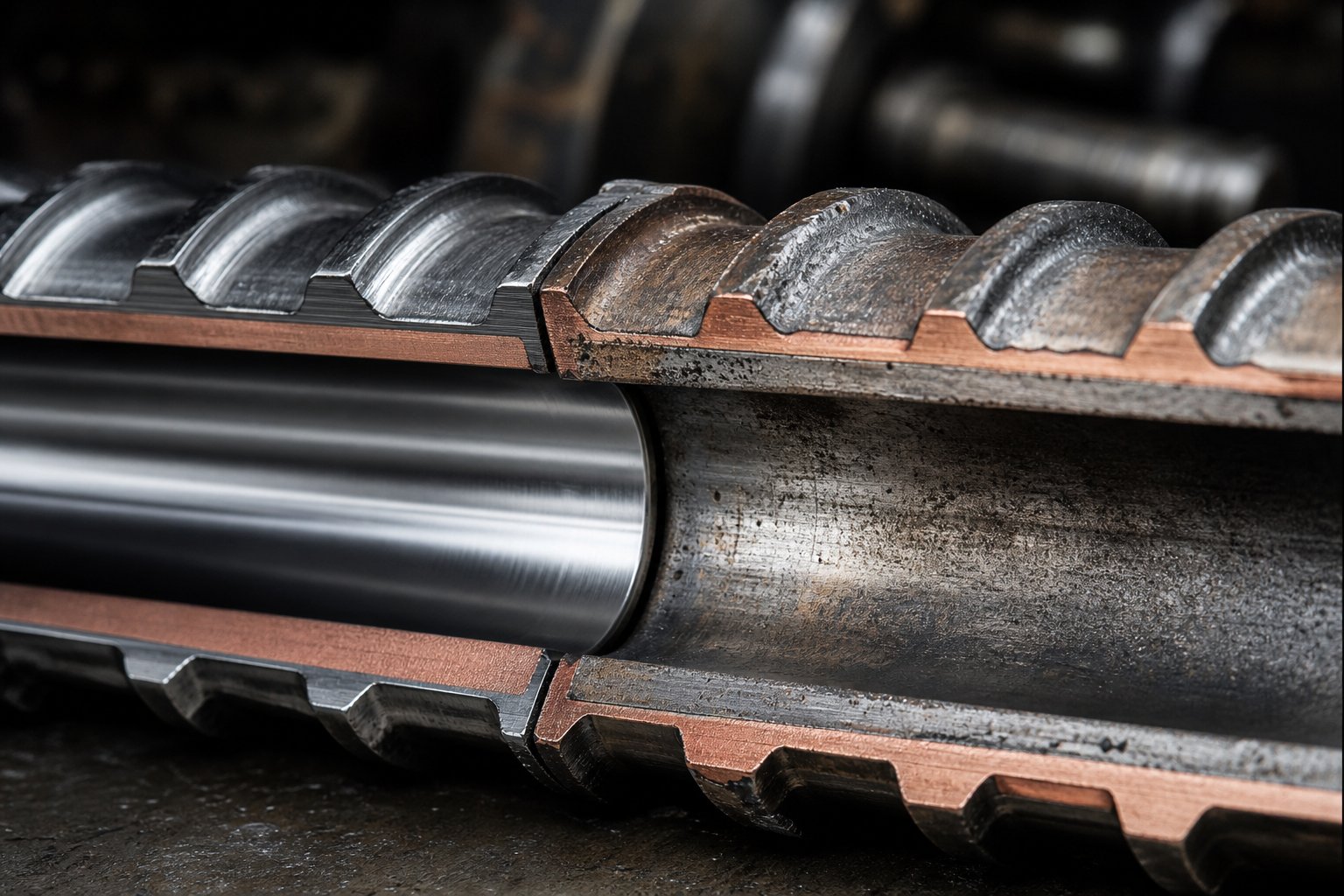
Worn screws and barrels do not announce themselves with a dramatic failure. They creep up on you—gradual throughput loss, slightly wider melt temperature variation, a batch that just barely misses spec. By the time an operator notices the output pulsing or product quality drifting, the twin screw barrel bore may already be eroded well beyond acceptable tolerances. Understanding how wear happens, which metallurgy fights it, and when to intervene is what separates a reactive maintenance culture from a proactive one that protects both uptime and product consistency.
Wear Mechanisms in Parallel Twin Screw Barrels
Three distinct mechanisms attack your twin screw and barrel components, and each leaves a characteristic fingerprint on the metal surface.
Abrasive wear is by far the most destructive in compounding applications—accounting for roughly 80% of all component wear in typical twin screw operations. Hard particles—calcium carbonate, glass fiber, talc, titanium dioxide—act like microscopic cutting tools, plowing material off barrel walls and screw flight lands with every rotation. You will notice abrasive damage most severely in the feed and melting zones, where solid particles still exist at high concentration, and in kneading sections where contact pressures peak. The sharp machined corners of screw and kneading elements appear rounded, smooth, and occasionally polished when abrasion takes hold.
Adhesive wear occurs when metal surfaces contact each other directly under insufficient lubrication from the polymer melt. Imagine starting the screws before the barrel reaches operating temperature—the viscous, partially molten material cannot form the hydrodynamic film that normally keeps flight tips separated from barrel walls. The result? Microscopic welds form between the surfaces, tearing material from one component and depositing it on another. Score marks on the barrel bore and flattened flight tips are telltale signs. As Xtrutech's wear analysis explains, screws left rotating at high speed between production runs—without material providing support—are particularly vulnerable to this mechanism.
Corrosive wear attacks through chemistry rather than mechanics. Processing halogenated polymers like PVC releases hydrochloric acid at elevated temperatures. Flame retardant packages, acidic coupling agents, and even moisture-induced hydrolysis generate corrosive species that pit and etch barrel surfaces. The damage appears as dimpled, pockmarked metal—visually distinct from the polished surfaces of abrasive wear. Corrosive wear is insidious because it weakens the surface layer, making it more susceptible to subsequent mechanical erosion in a compounding cycle of damage.
How do these mechanisms degrade performance? As barrel bore diameter increases beyond tolerance, the clearance between screw flight and barrel wall grows. This widening gap creates leakage flow—material slipping backward past the flight tip instead of being conveyed forward. The consequences cascade: reduced pressure generation, decreased mixing efficiency, lower throughput at constant speed, and inconsistent melt quality. Studies show excessive wear can reduce throughput by 10% to 30% and inflate energy consumption by 15% to 40%—numbers that make a compelling case for proactive barrel management.
Metallurgy Options for Barrel and Screw Protection
Selecting the right metallurgy for your screws and barrels is not a one-size-fits-all decision. The dominant wear mechanism in your specific process dictates which material grade delivers the best cost-per-kilogram-of-output economics over time.
- Nitrided steel (e.g., 38CrMoAlA): The entry-level standard for general-purpose compounding. Vacuum nitriding produces a hardened surface layer (typically 900–1100 HV) that resists moderate abrasion and adhesive contact. Suitable for unfilled or lightly filled polymer processing where wear rates are manageable. Typical service life ranges from 6 to 12 months under normal conditions. Cost-effective for processors running non-abrasive formulations.
- Bimetallic barrels (centrifugally cast alloy liners): A tough steel outer shell lined with a wear-resistant alloy layer—typically 2 to 4 mm thick—applied through centrifugal casting. The alloy liner achieves hardness levels of 58–65 HRC and provides two to three times the wear resistance of nitrided steel. Ideal for moderate to high filler content, masterbatch production, and recycling operations where abrasive particles are constant but not extreme. This is the workhorse metallurgy for most production compounding plants.
- Tungsten carbide-based coatings (HVOF applied): For the most punishing applications—high glass fiber loading, silicon carbide fillers, or extremely abrasive mineral compounds—tungsten carbide coatings deliver hardness of 70–75 HRC. Applied via high-velocity oxy-fuel spraying, these coatings extend service life three to five times beyond nitrided steel. The higher upfront cost is justified where unplanned downtime costs dwarf component prices.
- Corrosion-resistant alloys and coatings: When the primary threat is chemical rather than mechanical—PVC processing, fluoropolymer compounding, or formulations with acidic additives—nickel-based alloys or specialized stainless steel liners resist the pitting and etching that would rapidly destroy standard carbon steel surfaces.
The key insight? Match your metallurgy to your dominant wear mechanism. A recycling line processing contaminated post-consumer waste with mixed abrasive fillers demands bimetallic or tungsten carbide protection. A PVC pipe operation, by contrast, needs corrosion resistance above all else. Choosing the wrong metallurgy means either overpaying for unnecessary protection or under-protecting critical surfaces that will fail prematurely.
For processors evaluating barrel replacement or upgrade options, NANHAIYA's parallel twin screw barrel line exemplifies the purpose-built approach—barrels engineered specifically for compounding plants, pelletizing lines, masterbatch producers, and recycling operations where stable mixing and conveying under high-wear conditions define daily reality. Their focus on application-matched metallurgy and dimensional precision reflects the philosophy that a twin screw barrel is not a generic commodity but a performance-critical consumable.
Maintenance Scheduling and Wear Monitoring
When does a worn component actually need replacing? The short answer: when you can measure its impact on output or quality. The better answer: before it reaches that point.
Coperion's preventive wear diagnostics program demonstrates best-in-class practice: barrel bore measurement combined with high-resolution video inspection allows operators to map wear progression without fully dismantling the process section. Pulling the screws out is sufficient—barrel segments remain in place while a measurement device and HD camera slide through the bore, imaging the surface condition and quantifying diameter changes at every position.
For practical maintenance scheduling, consider this framework:
- Monthly: Visual inspection of screw elements during routine shutdowns. Look for rounded flight edges, polished surfaces (abrasion indicator), or pitting (corrosion indicator). Measure flight outer diameter against original specifications—a 5% reduction over three-quarters of the element length is a common replacement threshold.
- Quarterly: Bore diameter measurement at multiple axial positions using internal micrometers or bore gauges. Focus on high-pressure zones downstream of kneading sections and at melt seal locations where wear concentrates. A 5% bore diameter increase over a length of one screw diameter signals replacement is needed.
- Annually: Full disassembly inspection including shaft spline condition, barrel liner adhesion, cooling channel integrity, and thermocouple accuracy. This is also the time to evaluate whether your current metallurgy grade matches evolving production demands—if formulations have shifted toward more abrasive fillers, upgrading barrel metallurgy at the next replacement cycle avoids accelerated failure.
The economics are straightforward. Proactive replacement of a single barrel segment before bore erosion cascades into screw damage, quality drift, and unplanned shutdown costs a fraction of reactive emergency repair. For high-volume operations processing abrasive materials, annual wear-related costs can reach $100,000 to $300,000 when indirect losses from downtime, scrap, and efficiency degradation are included. A disciplined measurement program transforms that unpredictable expense into a plannable maintenance budget.
Barrel condition monitoring also serves as an early warning system for upstream process problems. If one barrel segment wears significantly faster than its neighbors, it often indicates a screw configuration issue—perhaps an overly aggressive kneading block creating localized pressure spikes, or a reverse element positioned where fill level runs excessively high. In this way, wear patterns become diagnostic data, telling you not just that something is wrong, but where in the process to look for the root cause.
Keeping screws and barrels within specification is ultimately a prerequisite for everything discussed in earlier sections—consistent mixing performance, predictable energy input, and stable output quality. Yet even a perfectly maintained machine only delivers its potential if it is appropriately sized for the intended production volume. The principles governing how parallel twin screw systems scale from a small laboratory unit to a multi-ton-per-hour production line introduce an entirely different set of engineering considerations.
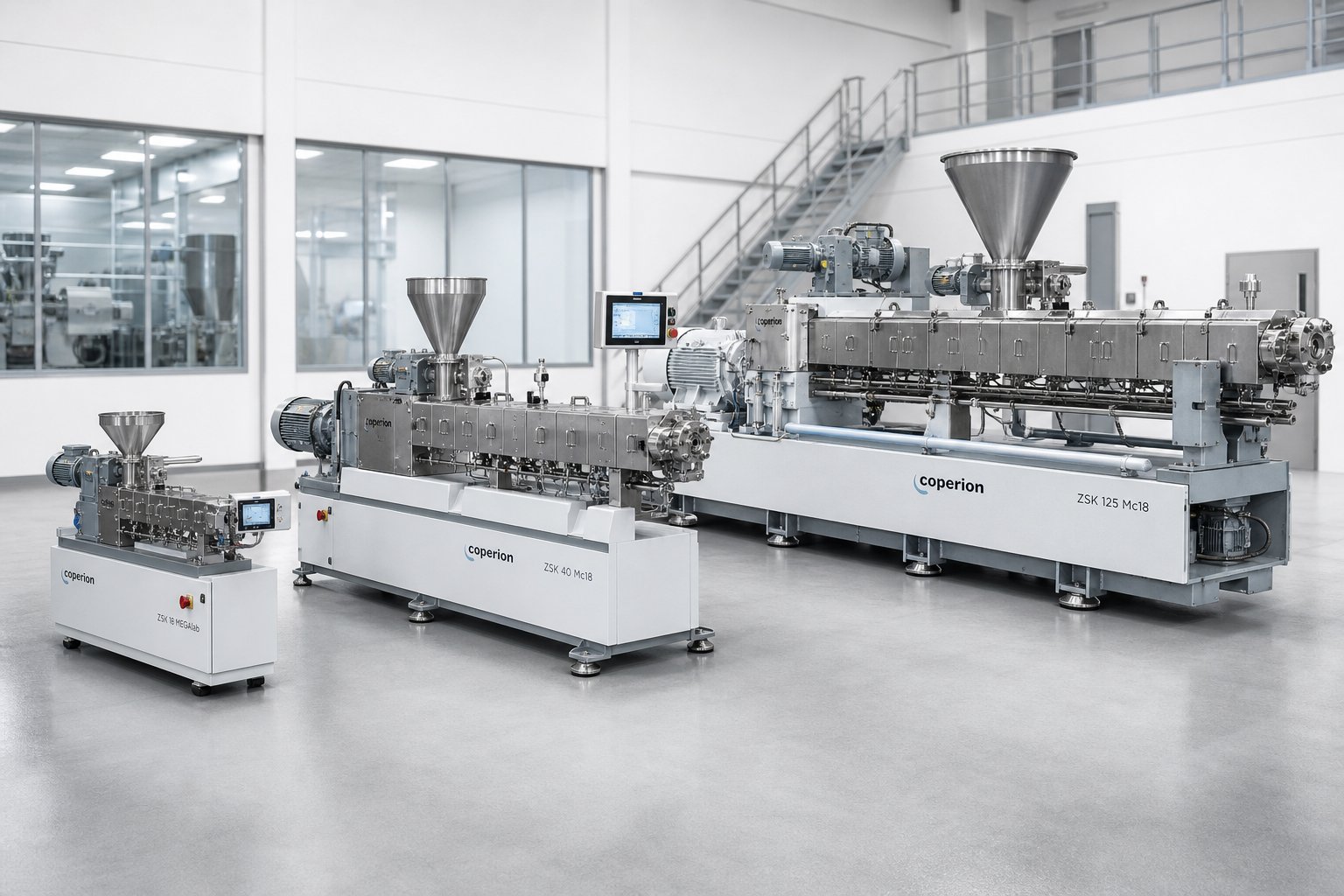
Scaling From Laboratory to Production Parallel Twin Screw Systems
A formulation that runs beautifully on a benchtop twin screw extruder does not automatically behave the same way on a production machine ten times its size. Scale-up is where promising lab results collide with the unforgiving physics of larger equipment—and where many compounding projects stall, burn budget, or produce off-spec material for weeks before the process stabilizes. Understanding why this happens, and what principles guide a successful transition, is one of the most valuable skills a process engineer can develop.
Lab-Scale Parallel Twin Screw Extruders and Their Role
A laboratory twin screw extruder—typically featuring screw diameters between 11 mm and 27 mm—serves as the proving ground for new materials and formulations. These compact machines consume minimal raw material, sometimes as little as a few hundred grams per run, making them ideal for screening polymer blends, evaluating additive packages, and establishing feasibility before committing expensive production time.
Modern lab twin screw extruder systems pack surprising capability into a small footprint. Compact models like the GS20 series feature screw diameters around 21.7 mm, throughputs of 5 to 15 kg/h, and servo-driven high-torque gearboxes that replicate the mixing intensity of much larger machines. Multiple heating zones, torque monitoring, and adjustable screw speed allow researchers to simulate industrial processing conditions with high precision and repeatability—critical for academic research and industrial product development alike.
The modular screw design philosophy carries over directly to small-diameter machines. A lab-scale unit uses the same families of conveying elements, kneading blocks, and mixing elements as its production-scale counterpart. This means the screw configuration you develop at the bench can, in principle, be translated to larger equipment while maintaining geometric similarity.
Here is the catch, though: not all phenomena scale linearly. Heat transfer behavior, fill dynamics, and shear rate distributions shift as diameter grows. A Dow case study on masterbatch scale-up demonstrated this vividly—optimized conditions from a 26 mm laboratory machine produced significant pressure fluctuations and phase separation when applied directly to a 40 mm pilot extruder. The same conditions failed even more dramatically on a 92 mm production machine, where solid polymer pellets discharged unmelted through the diverter valve. Lab results provide essential direction, but they always require validation and adjustment at larger scales.
Scale-Up Principles and Challenges
So how do you translate a working lab process to a production machine? Scale-up theory for parallel twin screw systems rests on two competing models, and real-world practice sits somewhere between them.
The cubic law treats the extruder interior as a three-dimensional volume. Since internal flow volume increases with the cube of the barrel diameter, throughput scales as Q ∝ D³. A fourfold increase in screw diameter theoretically delivers a 64-fold throughput increase. Technovel's scale-up analysis explains that this model assumes identical screw speed and shear rate at both scales—maximizing productivity but raising screw peripheral speed, which increases shear heating and can alter the material's thermal history.
The square law views the extruder as a two-dimensional heat transfer system. Barrel surface area—the primary pathway for heating and cooling the melt—increases only with the square of the diameter. Throughput under this model follows Q ∝ D², yielding a more conservative 16-fold increase for the same fourfold diameter jump. This approach prioritizes reproducing the temperature history and mixing state of the material, sacrificing some throughput gain for better quality consistency.
Real scale-up conditions rarely follow either law perfectly. As Technovel notes, the actual operating point sits between the cubic and square models—the engineer's job is to find the sweet spot that pushes volume as high as possible without sacrificing product quality.
Several challenges make this balancing act difficult:
- Heat transfer efficiency declines at larger diameters. Internal volume grows with D³ while barrel surface area grows with D². The result? A larger machine has proportionally less cooling and heating surface per unit of material, making barrel temperature control less effective at managing melt temperature.
- Specific mechanical energy (SME) must be matched across scales. The Dow case study showed that when SME dropped from 0.083 kWh/kg on the 26 mm extruder to just 0.026 kWh/kg on the 92 mm machine—a 69% reduction—the process failed completely. Only after screw design modifications raised the SME back to 0.086 kWh/kg did the production-scale process deliver homogeneous melt and stable pelletization.
- Screw design may require modification. Identical element sequences do not guarantee identical performance at different diameters. Melting zone length, kneading block arrangement, and reverse element positioning often need adjustment to compensate for altered fill dynamics and heat transfer ratios at production scale.
- L/D ratio is typically maintained during scale-up to preserve the number and proportion of processing zones. Throughput then scales approximately with the cube of the diameter ratio—assuming the process is not heat-transfer-limited.
Scale-up of a parallel twin screw extruder is a design process of selecting the optimal point between the cubic law and the square law—balancing throughput against quality reproducibility based on the specific material and process requirements.
Production-Scale Considerations
Production machines span a wide range—from 40 mm diameter units handling hundreds of kilograms per hour to 180 mm and larger platforms pushing multi-ton-per-hour throughput in high-volume commodity compounding. The right size depends on your target output, material characteristics, and the economic balance between a single large machine and multiple smaller units running in parallel.
From a theoretical standpoint, when quality reproducibility is the absolute priority, running multiple smaller extruders in parallel preserves the shear history, residence time, and temperature profile proven at development scale. However, floor space, labor, and capital investment often favor consolidation onto a single larger machine—provided the scale-up challenges above are addressed through systematic process development.
Selecting appropriately rated barrels and drive systems becomes increasingly important as machine size grows. Larger diameters amplify every force—torque loads on shafts, pressure against barrel walls, and thermal stress across heating zones. Under-specifying any of these components at the production scale creates bottlenecks that are far more expensive to correct after installation than during the specification phase.
The table below summarizes how key parameters shift across the three primary scales of parallel twin screw operation.
| Parameter | Lab Scale | Pilot Scale | Production Scale |
|---|---|---|---|
| Typical Screw Diameter | 11–27 mm | 30–50 mm | 50–180+ mm |
| Throughput Range | 0.5–20 kg/h | 20–200 kg/h | 200–10,000+ kg/h |
| Typical Applications | Material screening, formulation development, feasibility testing | Process validation, small batch production, scale-up parameter optimization | Full commercial compounding, masterbatch, recycling, reactive extrusion |
| Material Consumption | Minimal (grams to low kg) | Moderate (tens of kg per trial) | High (continuous operation) |
| Investment Level | Low to moderate | Moderate to high | High to very high |
| Scale-Up Role | Establish baseline SME, screw design, and process window | Validate scalability, identify heat transfer limits, refine screw configuration | Achieve target throughput with confirmed quality and process stability |
The progression from benchtop twin screw extruder to full production line is not a straight path—it is a series of deliberate engineering decisions at each scale. Every transition demands fresh validation of energy input, mixing quality, and thermal management. Skipping the pilot stage, or assuming that lab conditions translate directly to production, is the most common and most costly mistake in scale-up projects.
Ultimately, the machine you scale up to is only as capable as its weakest component. And in high-wear, high-throughput production environments, the component most likely to limit long-term performance—and the one that deserves the most careful specification—is the barrel itself.
Selecting the Right Parallel Twin Screw Barrel for Your Operation
A production-scale extruder represents a significant capital commitment—but the barrel bolted around those screws is the component that ultimately determines how long that investment keeps performing. Barrels wear. They corrode. They lose dimensional precision under thousands of hours of abrasive, high-temperature contact with filled polymer melts. And when they drift out of tolerance, every upstream optimization you have invested in—screw configuration, process parameters, scale-up validation—delivers diminishing returns.
Choosing the right barrel is not a purchasing decision you make once and forget. It is an ongoing technical evaluation that shapes total cost of ownership across every production campaign your line will run.
Key Selection Criteria for Parallel Twin Screw Equipment
When specifying a parallel twin screw system—or replacing worn components on an existing line—the equipment selection process extends well beyond brand name and price tag. Several decision factors interact, and getting any one of them wrong creates bottlenecks that are expensive to correct after installation.
Application type is the starting point. A compounding line running glass-fiber-reinforced nylon faces fundamentally different wear and torque demands than a reactive extrusion system processing bio-based polymers. Recycling operations introduce feedstock variability that stresses barrels and screws in ways that clean-resin compounding never does. Your equipment specification must reflect the actual materials and conditions the machine will encounter daily—not a generalized catalog rating.
Throughput requirements determine machine size, drive power, and barrel length. But throughput also influences wear rate: higher output means more material passing through every flight clearance per hour, accelerating abrasive erosion proportionally.
Material abrasiveness and corrosiveness dictate barrel metallurgy—the single most impactful specification for long-term durability. As discussed in the wear mechanisms section, mismatching metallurgy grade to your dominant wear mode can cut barrel life by half or more.
Mixing intensity and budget constraints round out the picture. Higher-performance metallurgy costs more upfront but frequently delivers lower cost per kilogram of output over the barrel's service life. The twin screw extruders market offers options from entry-level nitrided steel through premium tungsten carbide coatings, and the right choice depends entirely on your specific operating economics.
The landscape of twin screw extruder manufacturers spans established OEMs—names like Coperion, whose lineage traces back to the original Werner & Pfleiderer extruder platform that pioneered co-rotating technology, and Leistritz, known for its broad range of laboratory through production-scale machines—alongside specialized aftermarket suppliers focused exclusively on wear components. Whether you source barrels from your OEM or from an aftermarket twin-screw extruder manufacturer, the evaluation criteria remain identical. What matters is metallurgical competence, machining precision, and proven experience with your specific application conditions.
Why Barrel Quality Determines Long-Term Performance
You can think of the barrel as a consumable—especially in high-wear applications processing mineral fillers, glass fiber compounds, or recycled feedstock contaminated with abrasive particles. Its bore tolerance, alloy composition, and thermal management capability directly affect product quality, energy efficiency, and uptime. A barrel with inconsistent bore dimensions creates uneven flight clearances, which produce localized leakage flow, non-uniform shear distribution, and ultimately, the kind of subtle quality drift that is maddening to troubleshoot.
As Plastics Technology's screw and barrel lifecycle analysis emphasizes, original flight-to-bore clearances are typically minimal—on the order of 0.001 inch per side per inch of diameter—and any increase from wear degrades melting efficiency, mixing consistency, and pressure stability. Barrel quality at installation sets the baseline for how long those tight tolerances hold.
When evaluating barrel suppliers—whether OEM or aftermarket—processors should assess these critical factors:
- Application-matched metallurgy and design expertise: Look for suppliers who engineer barrels for specific processing conditions rather than offering generic solutions. NANHAIYA's parallel twin screw barrel line, for example, is purpose-built for compounding plants, pelletizing lines, masterbatch producers, and recycling operations—applications where durable barrels engineered for stable mixing and conveying under high-wear conditions are non-negotiable.
- Bore tolerance and dimensional precision: Tight bore tolerances—typically held within 0.15 mm to 0.30 mm clearance depending on machine size—are essential for consistent shear and heat transfer. Ask for documented inspection data, not just catalog claims.
- Metallurgy grade range: A capable supplier offers multiple metallurgy options—nitrided steel for general-purpose work, bimetallic liners for moderate abrasion, and premium alloys or coatings for extreme conditions. The ability to recommend the right grade for your specific formulation signals real application expertise.
- Temperature zone design: Barrel segments must integrate seamlessly with your heating and cooling infrastructure. Verify that cooling channel geometry, thermocouple port placement, and zone boundaries align with your process requirements.
- Lead time and supply reliability: A worn barrel waiting for replacement costs far more in lost production than the component itself. Evaluate suppliers on their ability to deliver consistently—especially for non-standard sizes or urgent replacements.
The Werner & Pfleiderer extruder platform may have established the co-rotating twin screw architecture decades ago, but the aftermarket ecosystem that has grown around it—and around every major OEM platform from Coperion extruder lines to Leistritz extruder systems—means processors have real choices when it comes to sourcing replacement barrels. The smartest operators treat barrel selection as a technical decision grounded in metallurgy, precision, and application fit, not simply a procurement exercise driven by lowest invoice price.
Ultimately, every topic covered in this guide—geometry, screw configuration, process optimization, wear management, and scale-up—converges on one practical reality: the parallel twin screw platform delivers extraordinary flexibility and performance, but only when every component in the system is specified, maintained, and replaced with the same engineering rigor that went into designing the process itself. The barrel is where that rigor pays its highest dividends.
Frequently Asked Questions About Parallel Twin Screw Technology
1. What is the difference between a parallel twin screw extruder and a conical twin screw extruder?
A parallel twin screw extruder features two screws of equal, constant diameter mounted on parallel axes, enabling fully modular screw element assembly and consistent free volume along the entire barrel length. A conical twin screw extruder uses tapered screws that decrease in diameter from feed to discharge, typically employing one-piece screw designs without modular capability. The parallel configuration supports all rotational modes (co-rotating and counter-rotating), handles frequent recipe changes through element rearrangement, and dominates compounding, masterbatch, and recycling applications. Conical designs are primarily used for PVC pipe and profile extrusion where their natural compression profile suits the material.
2. How does the Do/Di ratio affect parallel twin screw extruder performance?
The Do/Di ratio (outer diameter to inner/root diameter) typically ranges from 1.22 to 1.71 and creates a fundamental trade-off between throughput capacity and torque density. A higher Do/Di ratio produces deeper screw channels with greater free volume, allowing higher throughput and better intake of low-bulk-density materials, but limits shaft torque capacity. A lower Do/Di ratio provides shallower channels with higher torque density, ideal for energy-intensive compounding of engineering thermoplastics, but reduces volumetric capacity. Selecting the right ratio depends on whether your process is torque-limited or volume-limited.
3. What barrel metallurgy should I choose for my parallel twin screw extruder?
Barrel metallurgy selection depends on your dominant wear mechanism. Nitrided steel (900-1100 HV hardness) suits general-purpose processing with unfilled or lightly filled polymers. Bimetallic centrifugally cast barrels (58-65 HRC) offer two to three times the wear resistance of nitrided steel and serve as the workhorse for moderate to highly filled compounding lines. Tungsten carbide coatings (70-75 HRC) handle extreme abrasion from glass fiber or mineral fillers. For corrosive environments like PVC processing, nickel-based alloys resist chemical attack. Suppliers like NANHAIYA offer application-matched parallel twin screw barrels engineered for compounding plants, pelletizing lines, masterbatch producers, and recycling operations requiring stable performance under high-wear conditions.
4. Why do co-rotating twin screw extruders dominate polymer compounding?
Co-rotating intermeshing parallel twin screw extruders dominate compounding because their figure-eight material flow pattern delivers both dispersive and distributive mixing simultaneously. The self-wiping action eliminates dead zones, preventing thermal degradation of heat-sensitive polymers. Modern machines operate at speeds exceeding 1200 RPM, generating intense shear for filler dispersion and rapid melting. Their modular screw design allows practitioners to configure distinct processing zones—feeding, melting, mixing, venting, and metering—by simply rearranging elements on splined shafts. This combination of mixing intensity, processing flexibility, and throughput capacity makes them unmatched for applications ranging from nanocomposites to glass-fiber-reinforced engineering plastics.
5. How do you scale up a parallel twin screw extrusion process from lab to production?
Scale-up follows principles between two theoretical models: the cubic law (throughput scales as diameter cubed, maximizing productivity) and the square law (throughput scales as diameter squared, prioritizing quality reproducibility). The key is matching specific mechanical energy (SME in kWh/kg) across scales—if SME drops significantly at larger diameters, the process fails. L/D ratio is typically maintained during scale-up, while screw design may require modification because heat transfer efficiency declines at larger diameters. Successful scale-up proceeds through pilot validation (30-50 mm diameter) before committing to production scale (50-180+ mm), with fresh validation of energy input, mixing quality, and thermal management at each stage.
Written by
Nanhaiya Technical Team
Zhoushan Nanhaiya Plastic Machinery Co., Ltd.
The Nanhaiya technical team supports screw and barrel manufacturing projects through application review, technical communication, custom manufacturing coordination, and production and quality control.
Discuss Your Application
Related Articles
More insights on screw barrel technology and plastics processing.

Extruder Machine Decoded: From Raw Pellet To Finished Product
Oct 6, 2026
Learn how an extruder machine works, compare single-screw vs. twin-screw types, and get expert guidance on specs, troubleshooting, and selection.
Read Article
PE Pipe Making Machine Decoded: From Raw Resin to Flawless Pipe
Oct 4, 2026
Learn how a PE pipe making machine works, from resin to finished pipe. Covers components, material grades, automation, troubleshooting, and buyer selection tips.
Read Article
PVC Profile Making Machine Decoded: From Raw Resin To Profit
Oct 3, 2026
Learn how a PVC profile making machine works — extrusion process steps, key technical parameters, die design, calibration methods, maintenance, and total cost of ownership.
Read ArticleLooking for something else?
Search by material, symptom or product and jump straight to the relevant page.
These are navigation suggestions based on keyword matching — not a quotation, not a delivery commitment, and not a substitute for engineering review. Final specification is confirmed by our engineers against your drawings and processed material.
Need help with screw barrel selection?
Share your machine model, processed material and application. Our team can help with pricing and technical support.