

Understanding the Non Intermeshing Twin Screw Extruder
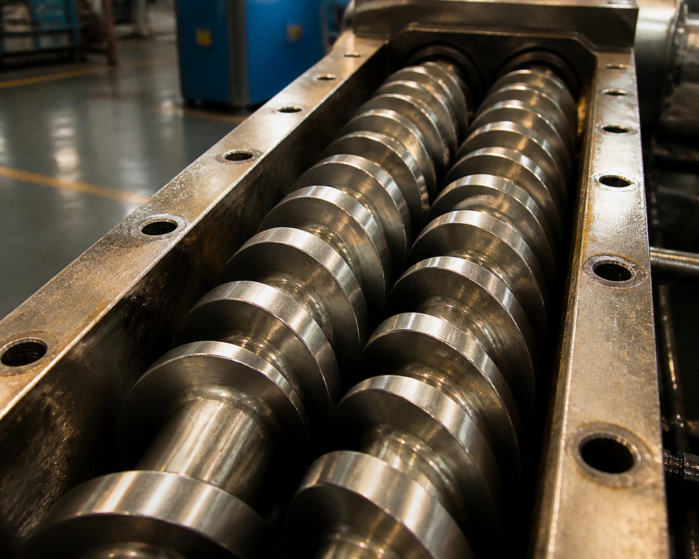
Imagine two screws spinning side by side inside a barrel — close enough to share the same processing space, yet never actually touching or interlocking. That is the core concept behind a non intermeshing twin screw extruder. Unlike the more widely discussed intermeshing designs where screw flights mesh together like gears, this configuration maintains a deliberate gap between the two screws, fundamentally changing how material is transported, mixed, and processed.
A non intermeshing twin screw extruder is a type of twin-screw extruder in which two parallel screws rotate within a shared barrel without their flights engaging or overlapping. Material conveyance relies on drag flow and open-channel transport rather than the positive displacement pumping generated by intermeshing screw geometry.
That distinction may sound subtle, but it creates dramatically different processing behavior — and for certain materials and applications, it makes all the difference.
What Defines a Non Intermeshing Twin Screw Extruder
In a standard twin screw extruder with intermeshing geometry, the flight of one screw fits snugly into the channel of the other. This tight engagement creates a positive displacement pumping action that forces material forward regardless of its frictional properties or viscosity. The result is high shear, efficient self-wiping, and precise material transport.
A non intermeshing system works differently. Each screw operates with a clear gap between its flight tips and the adjacent screw's surface. Because the twin screws never engage, there is no positive displacement action pushing material through the barrel. Instead, conveyance depends on friction between the polymer and the barrel wall and screw surfaces — a mechanism known as drag flow. The channels between the two screws remain open in both the lengthwise and crosswise directions, allowing material to transfer freely between them.
You'll notice the practical impact of this immediately: lower shear forces, reduced mechanical stress on the polymer melt, and a gentler thermal profile throughout the process. For heat-sensitive compounds that degrade under intense mechanical energy, these characteristics are not just preferable — they are essential.
Why This Technology Deserves Dedicated Attention
Here is the problem. Search for information on twin-screw extruders online, and you will find hundreds of resources dedicated to intermeshing co-rotating and counter-rotating designs. Non intermeshing configurations? They typically receive a paragraph or two — a footnote at best. This imbalance does not reflect the technology's importance. It reflects a content gap.
Non intermeshing twin screws occupy critical niches in polymer processing, from soft PVC compounding and thermoplastic elastomer blending to devolatilization and recycled material handling. Engineers and process designers evaluating this technology deserve more than a passing mention buried inside an article about intermeshing systems.
This article fills that gap. It serves as a dedicated, engineer-focused resource covering everything about non intermeshing twin screw technology: working principles and the physics behind lower shear processing, co-rotating versus counter-rotating configurations, ideal material and formulation matches, barrel and screw design considerations, maintenance and wear management, and a practical selection framework for choosing between non intermeshing, intermeshing, and single screw options. Every section targets the specific questions that existing resources leave unanswered.
The differences in how these machines move, mix, and process material start at the most fundamental level — classification and taxonomy. And that is exactly where the technical detail begins.
Complete Twin Screw Extruder Classification and Taxonomy
Every twin screw extrusion system traces back to a single branching point: do the screws engage each other, or don't they? That one question splits the entire twin screw extruder family into two fundamentally different engineering philosophies — and it determines everything from shear behavior to barrel geometry to the types of materials you can realistically process.
Before diving into working principles and application-specific advice, it helps to see the full picture. Where exactly does a non intermeshing twin screw extruder sit within the broader landscape? And why do so many engineers confuse the terminology?
Twin Screw Extruder Classification Hierarchy
The classification starts with a straightforward binary split and then branches further based on rotation direction and barrel geometry. Here is the full taxonomy laid out clearly:
- Twin Screw Extruders
- Intermeshing — Screw flights engage and overlap with each other
- Co-rotating (screws turn in the same direction)
- Counter-rotating (screws turn in opposite directions)
- Non-Intermeshing — Screw flights maintain a gap, with no engagement
- Co-rotating (screws turn in the same direction)
- Counter-rotating (screws turn in opposite directions)
- Intermeshing — Screw flights engage and overlap with each other
- Secondary classification layer — Barrel geometry
- Parallel barrel (constant screw diameter along the full length)
- Conical barrel (screws taper from a larger feed diameter to a smaller discharge end)
Intermeshing designs — particularly co-rotating configurations — dominate the compounding market. They are the workhorses of masterbatch production, reactive extrusion, and high-intensity dispersive mixing. Their tight screw engagement creates the spiral figure-eight flow path that delivers outstanding melt homogeneity and self-wiping capability.
Non-intermeshing designs, by contrast, occupy specialized niches. You'll find them where lower shear, gentler thermal history, or open-channel material conveyance offers a clear processing advantage — applications that intermeshing machines simply handle too aggressively. Think of it this way: intermeshing extruders are built for intensity, while their non-intermeshing counterparts are engineered for restraint.
Where Non Intermeshing Fits Among Screw Extruders
One source of confusion that trips up even experienced engineers is terminology. A double screw extruder described as "tangential" in one manufacturer's catalog is the same machine called an "open-mesh twin screw" in another technical paper, and a "non-engaging twin screw" in a third. All of these terms describe the same non-intermeshing category — two screws operating in a shared barrel with a gap between their flight tips, relying on drag flow rather than positive displacement.
Barrel geometry adds another layer to the classification. A parallel twin screw extruder maintains a constant screw diameter along its entire length, which is the more common configuration in non-intermeshing systems. A conical twin screw extruder, with screws that taper from a larger feed end to a smaller discharge end, appears more frequently in intermeshing counter-rotating designs — especially for PVC processing and applications requiring enhanced feed intake of bulky or low-density materials.
That said, conical non-intermeshing configurations do exist in specialized laboratory and pilot-scale equipment. The parallel layout, however, remains the standard for industrial-scale non-intermeshing twin screw extrusion because it offers greater design flexibility in screw element arrangement and simplifies barrel segment replacement.
The table below consolidates this taxonomy into a single visual reference — something you can use as a quick lookup when evaluating different extruder types or comparing supplier specifications:
| Category | Sub-Type | Screw Engagement | Typical Barrel Geometry |
|---|---|---|---|
| Intermeshing | Co-rotating | Fully engaged; self-wiping flight interaction | Parallel (most common); conical (lab/micro-compounders) |
| Intermeshing | Counter-rotating | Fully engaged; C-shaped enclosed chambers | Conical (dominant for PVC profiles); parallel available |
| Non-Intermeshing | Co-rotating | No engagement; open gap between flights | Parallel (standard industrial configuration) |
| Non-Intermeshing | Counter-rotating | No engagement; calender-like nip zone | Parallel (most common); conical (rare, specialty use) |
Notice the pattern: intermeshing systems need precise conjugate geometry between the two screws because their flights must mesh without collision. Non-intermeshing designs sidestep this constraint entirely. The screws operate independently of each other geometrically, which opens the door to different flight profiles, pitch variations, and channel depths that would be impossible in an intermeshing configuration.
This geometric independence is more than a design curiosity — it directly shapes how material moves through the barrel, how shear forces develop, and why non-intermeshing machines process certain polymers more effectively. Those mechanics are where the real engineering story begins.
Working Principle and Mechanism of Non Intermeshing Extruders
Geometric independence between the screws is not just a structural trait — it rewires the entire physics of how polymer moves, melts, and mixes inside the barrel. In intermeshing machines, the tightly engaged flights dictate the flow. In a non intermeshing twin screw extruder, something fundamentally different drives the process: friction.
Understanding this difference at the mechanical level is essential for any engineer evaluating whether drag-flow-based conveying fits a specific application. So let's break down exactly what happens inside these machines, step by step.
How Material Moves Through Non Intermeshing Screws
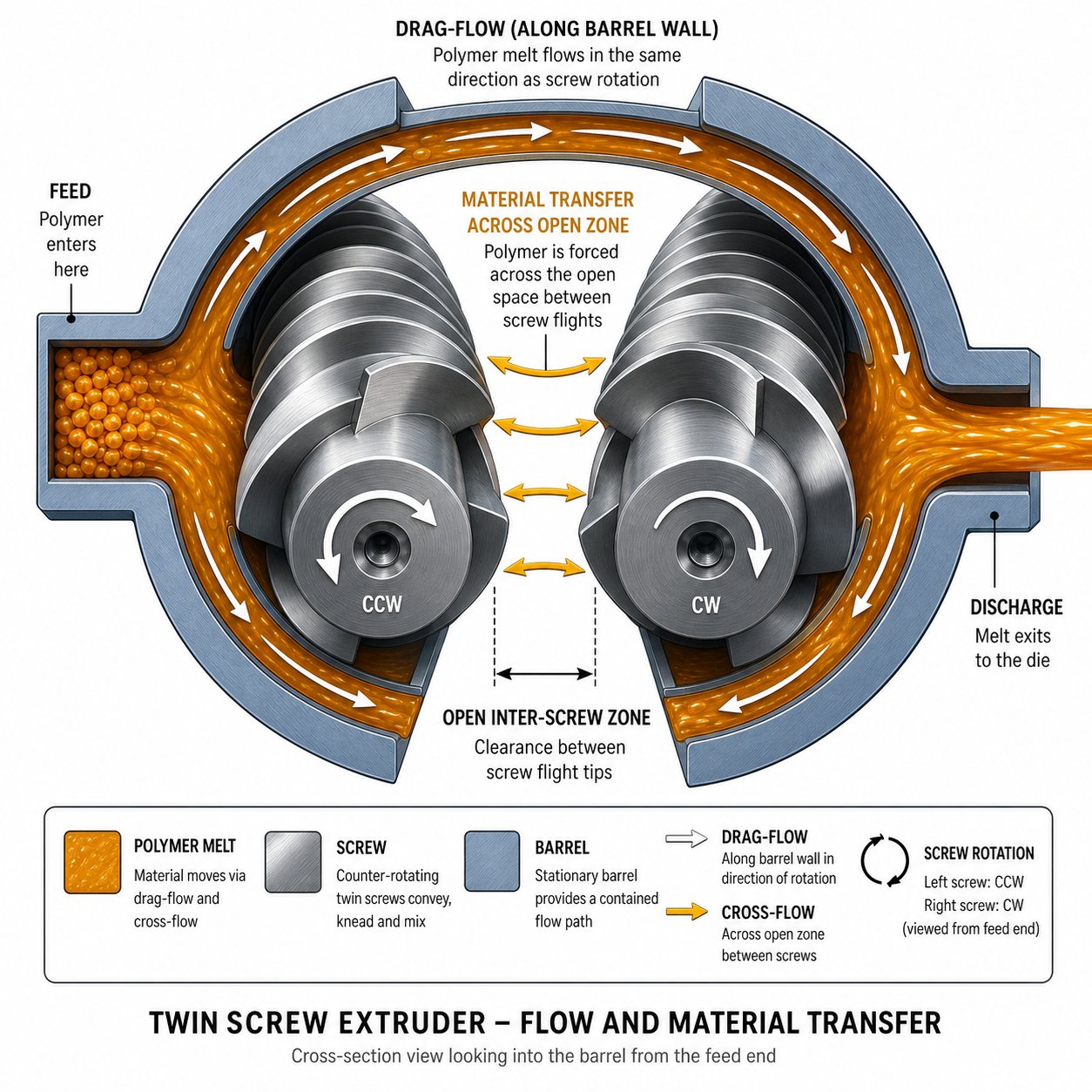
Picture two screws rotating side by side with a visible gap between their flight tips. No flight from one screw dips into the channel of the other. There is no interlocking, no wiping, and — critically — no positive displacement. Material does not get trapped between conjugate surfaces and pushed forward the way it does in an intermeshing extruder twin screw system.
Instead, conveyance relies almost entirely on drag flow. Here is how it works: the rotating screw surfaces and the stationary barrel wall create opposing frictional forces on the polymer. The barrel wall drags material forward relative to the screw root, and the screw flights guide it along the helical channel. This is the same fundamental transport mechanism that drives single screw extruders, and research confirms that non-intermeshing designs "resemble basically single screw extruders" in their transport behavior — they lack the superior positive-displacement transportability of closely intermeshing screws.
The key distinction from a single screw machine, however, is the open inter-screw zone. Because the flights don't intermesh, material can transfer freely between the two screws across an unobstructed gap. Imagine two adjacent helical channels that are open to each other rather than sealed off by meshing flights. Polymer melt flows back and forth between these channels as it travels down the barrel, creating longer, more varied flow paths compared to the tight, enclosed figure-eight trajectory of intermeshing co-rotating designs.
This open-channel architecture has several practical consequences:
- Longer flow paths — Material circulates between screws through multiple routes rather than being forced along a single constrained path, increasing distributive mixing opportunities.
- No self-wiping action — Without flight-to-flight contact, polymer can accumulate in low-shear zones. This is a disadvantage for materials prone to degradation from prolonged heat exposure, but an advantage for gentle blending operations.
- Unrestricted feed intake — The open geometry between screws avoids the feed restriction (sometimes called "feed necking") that can occur in intermeshing screw extruders when processing low-bulk-density fillers. Bulky or fluffy feedstocks drop into the open channels without being squeezed against interlocking flights.
The net effect is a transport system that moves material forward at lower mechanical intensity. You'll notice this immediately in reduced motor torque requirements and lower specific energy input per kilogram of throughput — both of which translate directly to gentler processing conditions.
The Physics Behind Lower Shear Processing
Shear rate in any extrusion process is fundamentally about velocity gradients. When polymer melt sits between two surfaces moving at different speeds, the difference in velocity across the gap creates a velocity gradient — and that gradient is the shear rate. The narrower the gap and the faster the relative motion, the higher the shear.
In intermeshing designs, the most intense shear occurs at two locations: the overflight gap (between the screw tip and barrel wall) and the intermesh zone (where the flight of one screw passes through the channel of the other). That intermesh zone is where the real intensity lives. Polymer is compressed into tight clearances between conjugate screw surfaces, generating extreme velocity gradients across very small distances. The result is high dispersive mixing — exactly what you want for breaking up agglomerates or achieving fine-scale blending of immiscible polymers.
Remove the intermesh, and you eliminate that entire high-shear compression zone. In a non intermeshing configuration, the only significant shear-generating clearance is the overflight gap between each screw tip and the barrel wall. The space between the two screws is comparatively wide and open. Velocity gradients across the melt in that inter-screw region are far lower because there are no opposing flight surfaces compressing material into narrow channels.
The shear force a polymer experiences during extrusion is directly proportional to the degree of screw engagement and the compression it creates. Without flight-to-flight intermesh, the primary source of high-intensity shear — forced compression through narrow conjugate clearances — is eliminated. The result is a fundamentally lower-shear processing environment.
This reduction in shear intensity produces a gentler thermal history. Viscous dissipation — the conversion of mechanical energy into heat within the melt — scales with shear rate. Lower shear means less internal heat generation. For heat-sensitive polymers with narrow windows between their processing temperature and degradation onset, this difference is not marginal; it is the boundary between usable product and thermal failure. Actual material testing has demonstrated that compounds processed through non-intermeshing systems show lower melt flow rates and higher impact strength — both indicators of suppressed thermal degradation compared to intermeshing processing at equivalent throughput.
There is another dimension to the physics worth noting: residence time distribution (RTD). In closely intermeshing counter-rotating screw extruders, the enclosed C-shaped chambers create a relatively narrow RTD — most polymer particles spend a similar amount of time in the machine. In non-intermeshing designs, the open channels and free inter-screw material transfer create a broader residence time distribution. Some material takes the shortest path; other portions recirculate through longer routes.
A broader RTD has trade-offs. On one hand, it means less uniformity in how long each polymer particle is exposed to heat and shear — a concern for applications requiring very tight thermal control. On the other hand, it enhances distributive mixing by ensuring material passes through multiple flow regions, and it improves devolatilization efficiency by giving volatiles more opportunity to migrate to barrel vents. For processes where removing moisture, solvents, or reaction byproducts is a priority, that broader distribution is a genuine asset.
These mechanical and thermal characteristics — drag-flow transport, reduced shear intensity, lower viscous dissipation, and broader residence time distribution — are not abstract theory. They define exactly which materials and formulations benefit from non-intermeshing processing, and they determine whether a co-rotating or counter-rotating configuration within this category is the better match for a given application.
Co-Rotating vs Counter-Rotating Non Intermeshing Designs
Rotation direction matters — even when the screws never touch. Most discussions about co rotating and counter rotating twin screw extruder configurations focus exclusively on intermeshing machines, where the difference between co-rotation and counter-rotation reshapes the entire flow field inside the intermesh zone. But here is what nearly every resource overlooks: rotation direction also changes the processing behavior of non-intermeshing twin-screw extruders in distinct and practically significant ways. The mechanisms are different, the trade-offs are different, and the best-fit applications diverge.
Let's unpack both configurations within the non-intermeshing family, starting with the one that prioritizes gentle distributive blending.
Co-Rotating Non Intermeshing Configuration
When both screws turn in the same direction without intermeshing, the material encounters a moderate, low-intensity mixing environment. At the nip region — the zone where the two screws are closest — polymer melt is carried from one screw channel toward the adjacent screw's surface. Because the surface velocities at this convergence point move in opposite directions (one screw's surface rises while the other descends), material is gently transferred between the two open channels rather than being forced through a tight clearance.
This natural exchange zone promotes distributive mixing: repeated splitting, reorientation, and recombination of melt streams without imposing the intensive dispersive forces characteristic of intermeshing co-rotating designs. You'll notice the practical result in the melt quality — good compositional uniformity at low shear rates, which is exactly what you want when processing formulations where preserving molecular weight or avoiding filler damage is the priority.
Co-rotating non-intermeshing configurations are often selected for:
- Devolatilization — The combination of open channels and moderate mixing promotes efficient surface renewal, allowing trapped volatiles, moisture, and solvents to migrate to barrel vents effectively.
- Gentle blending operations — Soft thermoplastic elastomers, color concentrates, and additive-laden compounds benefit from blending without excessive thermal input.
- Extended L/D processing — Because there are no geometric intermesh constraints, co-rotating non-intermeshing twin extruder systems can be specified at very long process lengths (60:1 L/D or beyond), providing extended residence for slow diffusion processes.
The trade-off is reduced dispersive mixing capability. If your application demands breaking up tightly bonded filler agglomerates or achieving nanoscale dispersion, this configuration will fall short. It blends well, but it does not forcefully shear.
Counter-Rotating Non Intermeshing Configuration
Switch the rotation direction, and the flow dynamics at the nip region change substantially. In a counter-rotating non-intermeshing setup, the two screw surfaces at the convergence point move in the same direction — both pulling material downward into the narrowing gap between them. This creates a calender-like nip effect, similar to the compression zone between two counter-rotating rolls in a calendering line.
As material is drawn into this narrowing gap, it experiences localized compressive and elongational forces. The polymer melt is squeezed, stretched, and then released as it exits the nip zone. This is not the same as the high-intensity dispersive shear of an intermeshing twin screw extruder — the gap is wider, and there are no interlocking flights creating forced compression — but it does generate meaningful dispersive mixing under gentle conditions. Research on counterrotating nonintermeshing TSEs confirms that screw elements can be matched or staggered at different points along the process length to fine-tune both pumping and mixing behavior, offering unusual design versatility.
Counter-rotation also affects residence time distribution differently. The calender nip tends to create more variability in how long individual polymer particles spend in the machine, typically producing even broader distributions than the co-rotating non-intermeshing alternative. Some material passes quickly through the nip zone; other portions recirculate through the open channels before reaching the nip again. For applications like high-level devolatilization — where extended and varied exposure to vacuum vents improves volatile removal — this broader RTD is advantageous.
Counter-rotating non-intermeshing designs see use in:
- Rubber compounding and mastication — The calender nip provides gentle compressive mixing without the heat buildup of intermeshing systems.
- High-level devolatilization — Process lengths of 100:1 L/D or more are possible because there are no intermesh-related geometric constraints, enabling very long residence times for stripping solvents and volatiles.
- Specialty compound processing — Formulations that benefit from moderate dispersive action combined with low overall shear intensity.
Side-by-Side Comparison
The table below breaks down the key performance parameters for each rotation direction within non-intermeshing twin-screw extruders. This is the comparison that most resources either skip entirely or conflate with intermeshing behavior — yet it is precisely the distinction that guides equipment selection for these specialized systems.
| Parameter | Co-Rotating Non Intermeshing | Counter-Rotating Non Intermeshing |
|---|---|---|
| Shear Intensity | Low — minimal nip compression | Low to moderate — calender nip generates localized compressive forces |
| Dominant Mixing Type | Distributive — melt splitting and recombination between open channels | Balanced distributive and mild dispersive via elongational nip effects |
| Residence Time Distribution | Broad — open channel flow with multiple recirculation paths | Very broad — calender nip adds variability in material transit time |
| Throughput Capacity | Moderate to high — efficient drag-flow conveying with low back-pressure | Moderate — nip compression can slightly restrict forward flow at high fill levels |
| Maximum Practical L/D | 60:1 or higher | 100:1 or higher (no intermesh geometric limits) |
| Common Applications | Devolatilization, gentle blending, additive incorporation | Rubber compounding, high-level devolatilization, specialty compounds |
Notice that neither configuration delivers the high-intensity dispersive mixing available from intermeshing co-rotating machines. That is not a flaw — it is the point. Both variants are engineered for restraint, and the choice between them comes down to whether your process benefits more from pure distributive blending or from the additional mild dispersive action of a calender nip.
Rotation direction defines the flow mechanics, but materials define the application. Certain polymers and compound types exploit these gentle processing characteristics far more effectively than others — and the specific formulations that benefit most from non-intermeshing processing are worth examining in detail.
Best Materials and Formulations for Non Intermeshing Processing
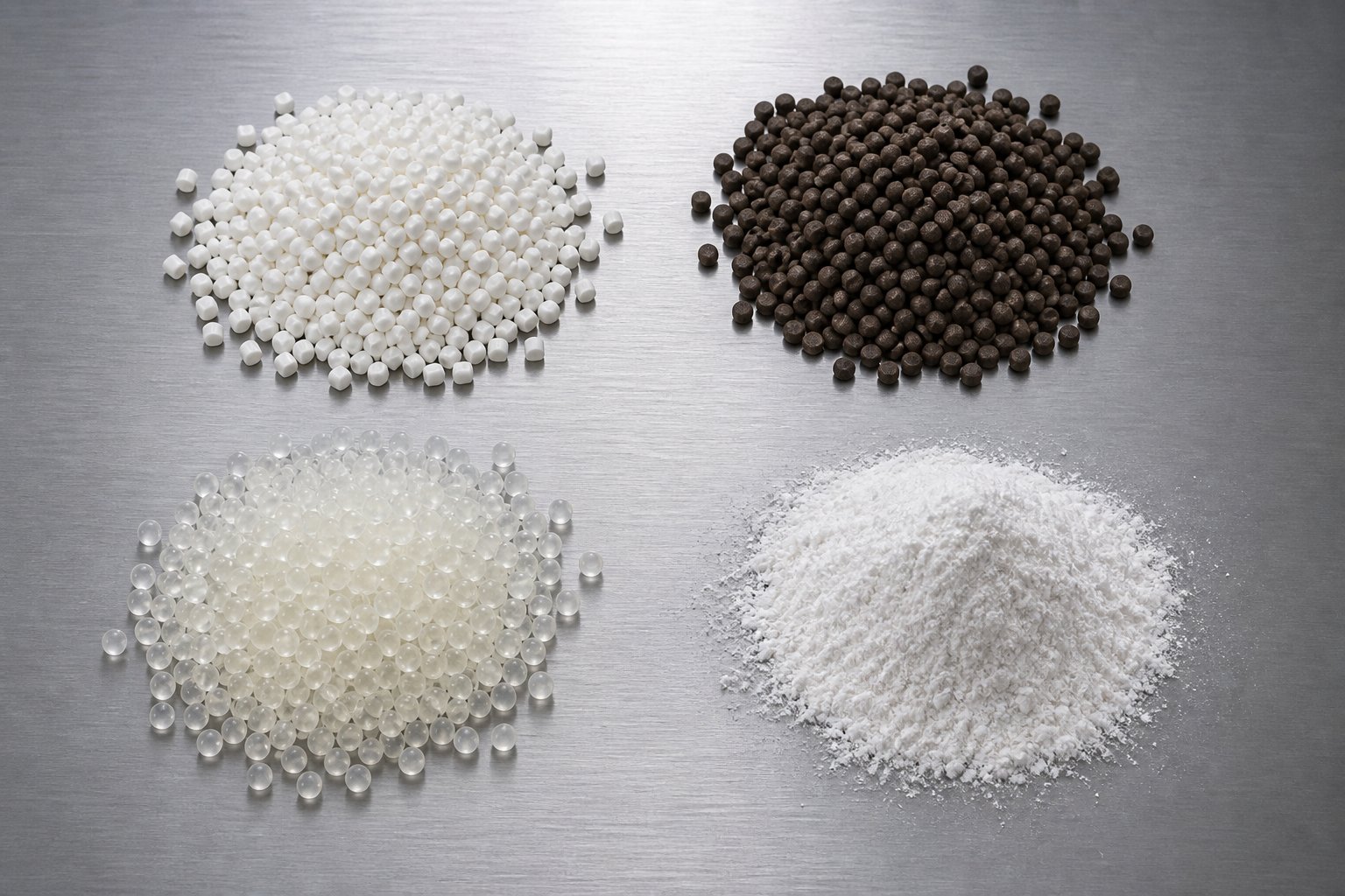
Low shear intensity and gentle thermal history sound like advantages in the abstract — but which specific materials actually need those characteristics? The answer is more varied than most engineers expect. Certain polymer families, filler-heavy formulations, and recycled feedstocks are not just compatible with non intermeshing twin screw extruder processing — they genuinely perform better in this environment than in any intermeshing alternative. The reasons trace directly back to the drag-flow mechanics and open-channel architecture covered earlier.
Here is where the engineering theory meets the production floor.
Heat-Sensitive Polymers and Specialty Compounds
PVC stands as the single most important material category for non-intermeshing processing, and the reason is rooted in basic thermal chemistry. The melting point of PVC sits in the range of roughly 100 to 260 degrees Celsius depending on formulation type and molecular weight, while its decomposition temperature — where hydrogen chloride gas begins releasing from the polymer backbone — starts at around 140 degrees Celsius for unmodified resin. That means the gap between the pvc melting temp required for processing and the onset of thermal degradation is dangerously narrow.
In an intermeshing extruder, the viscous dissipation generated by forced compression through tight screw clearances can push local melt temperatures past this threshold even when barrel zone setpoints look safe on the control panel. The result? Yellowing, black specks, HCl release, and degraded mechanical properties. A rigid PVC compound with no plasticizer is especially vulnerable because it lacks the internal lubrication that softens the melt and absorbs shear energy.
Non-intermeshing designs sidestep this problem by eliminating the primary source of excessive shear-induced heat. The melt temperature of pvc remains more controllable because the only significant shear-generating clearance is the overflight gap between each screw tip and the barrel wall — not the intense compression zone between interlocking flights. This is particularly valuable for rigid PVC formulations used in pipe, profile, and blow molding plastic pvc compounds where surface finish and structural integrity depend on avoiding even minor degradation events.
Soft PVC formulations — including pvc plastisol and polyvinyl chloride plastisol blends loaded with plasticizers, stabilizers, and pigments — present a different but related challenge. These compounds need thorough distributive mixing to achieve uniform plasticizer distribution without the excessive thermal input that causes plasticizer migration or color inconsistency. The open-channel distributive blending of a non-intermeshing system delivers exactly this balance: good compositional uniformity at gentle processing conditions.
PVC is the headline application, but it is far from the only heat-sensitive polymer that benefits. Consider these additional material families:
- Rubber compounds — Natural rubber and synthetic elastomers like EPDM and SBR require gentle mastication during compounding. Excessive shear generates frictional heat that can scorch the rubber prematurely, destroying its elastic properties. Non-intermeshing counter-rotating designs with their calender-like nip provide just enough compressive mixing for filler incorporation without triggering thermal runaway.
- Polybutylene succinate (PBS) — This biodegradable polyester is increasingly used in compostable packaging and agricultural films. PBS has a relatively low melt viscosity and is susceptible to hydrolytic chain scission and molecular weight loss under high-shear, high-temperature conditions. The lower specific energy input of non-intermeshing processing helps preserve the chain length that gives PBS its mechanical performance.
- Polyphenyl ether (PPE) blends — PPE-based alloys, commonly blended with polystyrene or polyamide, are valued for their dimensional stability and high heat resistance. However, the PPE phase itself is sensitive to oxidative degradation during melt processing. Reduced shear intensity and lower peak melt temperatures in non-intermeshing systems help maintain the molecular architecture of the polyphenyl ether component, preserving impact strength and heat deflection performance in the final blend.
- Thermoplastic elastomers (TPEs) — Soft-touch overmolding compounds and flexible tubing formulations benefit from gentle blending that avoids breaking down the elastomeric phase morphology during compounding.
The common thread across all these materials is the same: a narrow processing window where small increases in shear or temperature produce disproportionately large quality losses. Non-intermeshing technology turns that vulnerability into a manageable engineering variable rather than a production risk.
High-Fill Compounds and Recycled Material Processing
Material sensitivity is one reason to choose non-intermeshing processing. Formulation complexity is another — and high-filler-loading compounds illustrate this clearly.
Imagine compounding a polyolefin filled with 70 percent or more calcium carbonate (CaCO3) by weight. In an intermeshing extruder, the tight clearances between meshing flights create localized pressure spikes as this dense, abrasive mixture is forced through narrow gaps. Those pressure peaks cause two problems simultaneously: they generate excessive heat at the filler-polymer interface, and they can actually re-agglomerate filler particles that were already partially dispersed — defeating the purpose of the compounding step.
In a non-intermeshing system, the open screw geometry avoids these concentrated pressure zones. Material moves through wide, unrestricted channels where pressure builds gradually rather than in sharp peaks. The result is more uniform filler distribution with lower energy input per kilogram — a meaningful advantage when processing economics depend on maximizing filler content while maintaining acceptable melt quality.
High-fill applications that benefit from this approach include:
- CaCO3-filled masterbatch — Filler loadings of 60 to 80 percent are common in cost-reduction masterbatch production. The open channel geometry prevents the nozzle plugging and torque spikes that intermeshing machines experience at these extreme fill levels.
- Talc and mica-filled engineering compounds — Platelet-shaped fillers like talc benefit from distributive rather than dispersive mixing to maintain their aspect ratio, which directly controls the stiffness and barrier properties of the final compound.
- Wood-plastic composites (WPC) — Natural fiber fillers are thermally fragile and mechanically delicate. Excessive shear breaks down fiber length, reducing the reinforcing effect. Non-intermeshing processing preserves fiber integrity better than high-intensity alternatives.
Devolatilization represents another application where non-intermeshing designs demonstrate a structural advantage. The broader residence time distribution and open inter-screw channels discussed in earlier sections create ideal conditions for volatile removal. Material spreads across a larger exposed surface area as it transfers between screws, and the varied flow paths ensure that fresh polymer surfaces are continuously presented to vacuum vents. This is critical for stripping residual solvents from solution-polymerized elastomers, removing moisture from hygroscopic engineering resins, and eliminating reaction byproducts from post-reactor polymer streams.
Recycled material processing has become one of the fastest-growing application areas for non-intermeshing technology. Recycled feedstocks — whether post-consumer, post-industrial, or mixed-polymer regrind — arrive with inherent variability. Contamination levels fluctuate batch to batch. Moisture content is unpredictable. Mixed-polymer compositions create phases with different melt viscosities and thermal sensitivities. Intermeshing machines, optimized for consistent virgin feedstocks, can struggle with this variability because their tight clearances amplify the effects of contaminants and viscosity mismatches.
Non-intermeshing extruders handle this variability more gracefully. The open geometry tolerates off-spec material without the torque spikes or pressure surges that force intermeshing systems into frequent shutdowns. The lower shear environment reduces degradation of already-compromised polymer chains — chains that have already been through at least one processing cycle and cannot afford further molecular weight loss. For recycling operations processing mixed-color HDPE flake, contaminated PP regrind, or film scrap with residual printing inks and adhesives, this forgiving processing character translates directly into higher uptime, fewer rejects, and more consistent pellet quality.
Material selection drives machine selection — but the barrel and screw components that contain and shape the process impose their own constraints on what a non-intermeshing system can achieve. Design choices at the component level determine whether the theoretical advantages of this technology translate into real-world production performance.
Barrel and Screw Design Considerations for Non Intermeshing Extruders
Every advantage a non intermeshing twin screw extruder offers — lower shear, gentler thermal history, open-channel flow — ultimately depends on how the barrel and screws are engineered at the component level. Get the hardware wrong, and the theoretical benefits never materialize on the production floor. Yet barrel and screw design for non-intermeshing systems receives almost no dedicated coverage in the existing literature, even though the engineering considerations differ meaningfully from intermeshing machines.
Here is what process engineers actually need to know about the hardware that makes this technology work.
How Barrel Design Differs in Non Intermeshing Systems
The most immediate difference is bore geometry. In an intermeshing twinscrew extruder, the barrel bore must maintain extremely tight tolerances at the intermesh zone — the region where both screw profiles overlap. Even small deviations in bore alignment at this junction cause uneven wear, metal-to-metal contact, and premature screw failure. Non-intermeshing barrels sidestep this constraint entirely. Because the screws maintain a deliberate gap between their flight tips, the bore geometry can be more open, and the tolerance demands at the screw-to-screw zone are significantly relaxed.
This relaxed geometry does not mean barrel engineering is simpler. It means the design priorities shift. In intermeshing systems, wear concentrates at two locations: the overflight gap (screw tip to barrel wall) and the intermesh clearance zone (screw-to-screw contact). In non-intermeshing designs, there is no screw-to-screw contact zone. Wear concentrates primarily on the barrel inner wall surfaces — especially in the high-drag-flow regions where polymer friction against the barrel liner is doing the work of material transport.
This changes how barrel liner materials and surface treatments are selected. Rather than optimizing for both adhesive wear at the intermesh and abrasive wear at the barrel wall simultaneously, engineers designing non-intermeshing barrels can focus liner metallurgy specifically on abrasion resistance at the barrel ID. When processing highly abrasive compounds — CaCO3 at 70 percent loading, or glass-reinforced formulations — choosing the right barrel liner grade becomes the single most important wear management decision.
Temperature zone control also interacts differently with non-intermeshing systems. Because the residence time distribution is inherently broader, material in the barrel spends varying amounts of time in each heating or cooling zone. A polymer particle traveling the shortest path through the open channels receives less thermal input from barrel heaters than one recirculating through multiple inter-screw transfer zones. Process engineers compensate by using tighter barrel zone temperature gradients and more responsive PID control tuning. Modern modular barrels with internal cooling bores positioned close to the liner — the current state-of-the-art design for twin screw systems — help maintain thermal uniformity even with the variable residence patterns characteristic of non-intermeshing processing.
For materials with exceptionally high processing temperatures, such as compounds demanding resistance near the heat distortion temperature of advanced engineering resins like polyamide-imide, barrel metallurgy must also resist corrosion and thermal fatigue over sustained production campaigns. When polyetheretherketone properties are being targeted in blended systems — where maintaining melt integrity at elevated temperatures is critical — barrel liner durability under these extreme conditions directly determines achievable production uptime.
Screw Geometry Parameters That Drive Performance
If barrel design sets the stage, screw geometry writes the script. In non-intermeshing configurations, four key design variables control virtually every aspect of processing performance: flight depth, pitch, helix angle, and the gap distance between the two screws.
Here is how each parameter influences the process:
- Flight depth — Deeper channels increase the free volume available for material transport, boosting throughput capacity. However, as extrusion engineering principles confirm, excessively deep grooves reduce screw root strength and create uneven temperature distribution across the channel cross-section, because heat must transfer across a larger melt pool thickness from the barrel wall to the screw root.
- Pitch — The axial distance between flights determines how quickly material advances per screw revolution. A higher pitch means faster conveying and shorter residence time. A lower pitch slows the forward velocity and extends residence, which can improve mixing and devolatilization. In non-intermeshing systems, pitch can even vary between the two screws — something impossible in intermeshing designs where both screws must maintain synchronized geometry.
- Helix angle — Closely related to pitch, the helix angle affects both the conveying efficiency and the frictional drag balance between barrel wall and screw surface. Angles around 17 degrees suit most pellet feedstocks, while 30 degrees improves intake of powdered materials — a relevant consideration for high-filler non-intermeshing applications.
- Inter-screw gap distance — This is the parameter unique to non-intermeshing design. The gap between the two screws' flight tips determines how freely material transfers between the channels. A wider gap increases distributive mixing but reduces the mild compressive effects at the nip zone. A narrower gap enhances nip compression (especially in counter-rotating configurations) but begins approaching the tight-clearance behavior of intermeshing systems.
The critical advantage process engineers gain with non-intermeshing screws is geometric independence. In intermeshing machines, both screws must maintain conjugate geometry — the profile of each screw is mathematically constrained by the other so flights mesh without collision. Change the flight depth on one screw, and the other must change to match. Non-intermeshing screws face no such constraint. Each screw can have a different flight depth, a different pitch, or even a different number of flight starts at various points along the process length. This freedom allows engineers to create staggered or mismatched screw configurations that tune conveying rate, mixing intensity, and thermal input independently at different barrel zones — a flexibility that research literature identifies as largely untapped potential in non-intermeshing design.
The table below summarizes the key barrel and screw design differences between non-intermeshing and intermeshing systems, giving engineers a side-by-side reference for hardware specification decisions:
| Design Consideration | Non Intermeshing Twin Screw | Intermeshing Twin Screw |
|---|---|---|
| Barrel Bore Tolerance | Relaxed at inter-screw zone; standard at barrel wall | Tight tolerances required at both intermesh zone and barrel wall |
| Primary Wear Location | Barrel inner wall (abrasive drag-flow wear) | Barrel wall and screw-to-screw intermesh clearance zone |
| Barrel Liner Focus | Optimized for abrasion resistance at barrel ID | Must balance adhesive wear at intermesh and abrasive wear at barrel wall |
| Temperature Zone Sensitivity | Higher — broader RTD causes variable thermal exposure per zone | Lower — tighter RTD produces more uniform zone-by-zone thermal history |
| Screw Geometry Constraint | Independent — each screw can have unique flight profiles | Conjugate — both screws must maintain synchronized meshing geometry |
| Design Freedom for Flight Profiles | High — mismatched pitch, depth, and starts are possible | Limited — changes to one screw require matching changes on the other |
| Maximum Practical L/D Ratio | 60:1 to 100:1+ (no geometric intermesh constraints) | Typically 30:1 to 50:1 (limited by intermesh alignment over length) |
You'll notice a pattern in this table: non-intermeshing hardware trades tight-tolerance precision for design flexibility. That trade-off is not a compromise — it is a deliberate engineering choice that enables the gentler processing, broader application range, and extended barrel lengths that define this technology's niche.
Design flexibility, however, introduces its own challenge: wear. Without conjugate screw surfaces constraining material flow, the barrel wall bears more of the frictional burden. Over time, that burden translates into wear patterns, efficiency losses, and maintenance decisions that differ fundamentally from what intermeshing operators encounter — a topic that deserves its own dedicated examination.
Maintenance and Wear Management in Non Intermeshing Extruders
Barrel walls bearing more of the frictional burden is not an abstraction — it shows up as measurable metal loss, declining output rates, and eventually unplanned production shutdowns. Yet virtually no online resource covers how wear actually develops inside a non intermeshing twin screw extruder, what the warning signs look like, or how replacement strategies differ from intermeshing machines. That gap leaves maintenance teams and process engineers guessing when they should be planning.
Here is a practical breakdown of where wear happens, why it accelerates, and how to manage it for maximum service life.
Wear Patterns Unique to Non Intermeshing Configurations
In an intermeshing twin screw extruder, wear concentrates at two distinct zones. The first is the overflight gap — the narrow clearance between each screw's flight tip and the barrel wall. The second, and often more severe, is the intermesh clearance zone where the flight of one screw passes through the channel of the other. Research on closely intermeshing counter-rotating machines demonstrates just how punishing this second zone can be: separating forces exceeding one metric ton develop in the calender gap, pushing screws toward the barrel wall and causing concentrated abrasive wear between the 30-degree and 60-degree angles from the vertical.
Non-intermeshing designs eliminate that entire screw-to-screw wear mechanism. Because the flights never engage, there are no calender-gap separating forces bending the screws into the barrel bore. No adhesive wear from metal-to-metal screw contact. No flight-tip erosion from conjugate surface interaction. The wear pattern simplifies — but it does not disappear.
What remains is predominantly abrasive wear on the barrel inner surface and the flight tips of each individual screw. Here is why: in a drag-flow-dominant conveying system, the barrel wall is doing most of the work. Polymer and filler particles press against the barrel liner under frictional force as the rotating screws push material along the helical channel. That continuous sliding contact between abrasive compounds and the barrel ID is where metal loss accumulates over thousands of operating hours.
The wear distribution along the barrel length is not uniform, either. Industry analysis of twin screw wear zones identifies several high-intensity areas that apply directly to non-intermeshing systems:
- Feed zone — Solid granules, powder, and unmelted filler particles enter the barrel and grind against the wall under high contact pressure. This is pure mechanical abrasion, and it is especially severe when feeding pre-blended dry compounds with hard mineral fillers.
- Filler incorporation zone — When glass-reinforced compounds or CaCO3-heavy formulations encounter the screw channels, particulate abrasion intensifies. Glass fibers entangle at the feed port and shear during rotation, creating sharp fragments that score the barrel surface. Imagine fine sandpaper spinning against the barrel ID at every revolution — that is essentially what happens when processing glass reinforced polyester or similar abrasive-filled materials.
- Discharge zone — Gravity causes the cantilevered screw ends to sag slightly, and the resulting screw deflection pushes flight tips against the bottom of the barrel bore. Even in non-intermeshing systems, this gravity-induced deflection creates a localized high-wear region near the die end.
Processing compounds filled with silica phenolic particles or reinforced with poly para phenylene terephthalamide fibers adds another dimension of abrasive severity. These low friction plastic additives and reinforcements are valued for their tribological performance in finished parts, but during extrusion they behave as hard, abrasive particulates that accelerate liner erosion — especially in the feed and transition zones where they contact the barrel wall in solid or semi-solid form.
Recognizing the Signs of Excessive Wear
Barrel wear does not announce itself with a single dramatic failure. It creeps in gradually, and the symptoms are easy to misattribute to other process variables if you are not watching for them. Here are the indicators that experienced operators monitor:
- Loss of conveying efficiency — As the overflight gap widens due to flight tip erosion, more material leaks back over the screw flights instead of being pushed forward. You'll see this as declining throughput at the same screw speed, or as a need to increase RPM to maintain output.
- Increased melt temperature variability — A worn barrel with uneven liner thickness transfers heat unevenly. Hot spots develop where the liner has thinned, and cooler zones persist where it remains intact. The result is melt temperature swings that show up as inconsistent product quality downstream.
- Declining output consistency — Surging, pulsating die pressure, and fluctuating pellet weight all point to a loss of the stable drag-flow conveying that non-intermeshing systems depend on. When the barrel-to-screw clearance becomes irregular, the frictional balance that drives material forward breaks down unevenly along the barrel length.
- Rising specific energy consumption — A worn barrel-screw system demands more motor energy per kilogram of output because the inefficient clearances waste mechanical work as internal recirculation rather than forward conveyance.
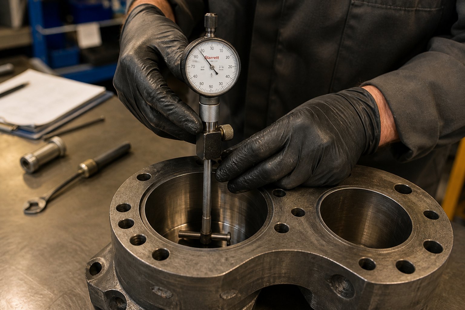
- Visual bore inspection evidence — Scoring, grooving, or visible diameter enlargement on bore gauge measurements confirm what the process data suggests. The 90 mm intermeshing barrel documented in published research showed maximum diameter wear at the 45-degree position after over 10,000 hours of operation with highly filled PVC. Non-intermeshing barrels exhibit similar angular wear patterns but concentrated on the barrel wall rather than at the intermesh zone.
Replacement Strategies and Long-Term Cost Considerations
Here is where non-intermeshing systems offer a genuine maintenance advantage. Because there is no screw-to-screw contact zone generating separating forces and adhesive wear, the most aggressive wear mechanism in intermeshing machines simply does not exist. For many applications — particularly those processing non-abrasive or moderately filled compounds — this translates to longer barrel and screw service intervals compared to intermeshing alternatives running similar materials.
That advantage narrows, and can even reverse, when processing highly abrasive formulations. CaCO3 loadings above 60 percent, glass fiber reinforcements, or mineral-filled masterbatch production subject the barrel liner to relentless abrasive contact. In these scenarios, barrel replacement intervals are driven primarily by liner abrasion rate, and the absence of intermesh wear provides only marginal benefit.
Regardless of the application, the quality of replacement barrel components is the single most controllable variable in managing long-term wear costs. Barrel liners manufactured with inferior metallurgy wear faster, fail unpredictably, and force unplanned shutdowns that cascade into missed delivery schedules and scrap material costs. Selecting replacement barrels from suppliers with deep expertise in wear-resistant metallurgy — including bimetallic liner options, nitrided steel grades, and powder metallurgy compositions — is the most effective strategy for minimizing total cost of ownership.
For compounding producers, recycling plants, and pelletizing operations running non-intermeshing equipment, NANHAIYA's Parallel Twin Screw Barrel line offers replacement and custom-engineered barrels designed specifically for high-wear processing environments. Their product range supports the barrel liner grades, bore tolerances, and modular configurations that non-intermeshing systems demand — particularly in applications involving abrasive fillers, recycled feedstocks, and extended-length barrel assemblies where liner durability determines achievable production uptime.
A structured maintenance inspection program is the foundation that makes any replacement strategy cost-effective. Here are the key checkpoints and timing indicators to build into your preventive maintenance schedule:
- Bore diameter measurement — Use a bore gauge at regular intervals (every 2,000 to 4,000 operating hours for abrasive compounds, every 6,000 to 8,000 hours for non-abrasive materials). Track diameter growth over time to predict replacement timing before performance degrades.
- Flight tip clearance check — Measure the gap between screw flight tips and barrel wall at multiple axial positions. A clearance increase exceeding 50 percent of the original specification typically signals the need for screw refurbishment or replacement.
- Melt temperature profile trending — Log zone-by-zone melt temperature readings weekly. Sudden deviations from established baselines often indicate localized liner thinning before bore gauge measurements confirm it.
- Throughput-at-speed tracking — Record output rate at a fixed screw RPM and compare monthly. A steady decline of 5 to 10 percent or more at constant speed points to progressive wear reducing conveying efficiency.
- Visual inspection during scheduled shutdowns — Pull screws and inspect both the screw surfaces and barrel bore for scoring, grooves, pitting, or discoloration patterns. Photograph and document each inspection to build a wear history that informs future replacement timing decisions.
- Vibration and torque monitoring — Rising vibration signatures or erratic torque readings can indicate screw deflection from worn barrel surfaces, even in non-intermeshing systems where deflection forces are lower than in intermeshing configurations.
The central takeaway is straightforward: non-intermeshing extruders wear differently, often more slowly, but they still wear. Understanding where metal loss concentrates, what process signals to watch for, and when to invest in quality replacement components is what separates operations running at 95 percent uptime from those chasing chronic downtime problems.
Knowing how to maintain the machine is half the equation. The other half is knowing whether you should have selected this machine in the first place — a decision that depends on a structured comparison between non-intermeshing, intermeshing, and single screw options across every parameter that matters to a process engineer or equipment buyer.
Selection Guide and Decision Framework for Engineers
Knowing how a machine wears tells you how to keep it running. Knowing whether it was the right machine to begin with determines whether all that maintenance effort is protecting a wise investment or propping up a poor one. Yet despite the critical importance of this choice, no widely available resource gives engineers a structured framework for deciding when a non intermeshing twin screw extruder actually beats the alternatives — and when it does not.
That gap leads to expensive mistakes. Facilities over-specify intermeshing machines for applications that never needed high-intensity dispersive mixing. Others default to single screw simplicity and discover too late that their blending requirements exceed what one flight path can deliver. The decision should not be based on habit or catalog marketing — it should follow directly from material behavior, process goals, and total cost of ownership.
Here is a practical decision framework built for exactly that purpose.
When to Choose Non Intermeshing Over Intermeshing Designs
Think of this decision as a diagnostic checklist. If your application checks multiple boxes in the following list, non-intermeshing processing deserves serious consideration over its intermeshing counterpart:
- Heat-sensitive polymers — Materials like rigid PVC, certain TPEs, and biodegradable polyesters where even moderate shear-induced temperature spikes cause chain scission, discoloration, or decomposition. If your melt temperature window is narrow, eliminating the high-shear intermesh zone is the most direct path to staying inside it.
- Molecular weight preservation — Formulations where maintaining polymer chain length is critical to end-product performance. Cross linked poly structures, for instance, rely on intact network architecture. Any pre-crosslinking degradation during compounding undermines the downstream polyethylene crosslinking step or cocure process that establishes final mechanical properties. Gentler processing preserves the base resin quality that those later reactions depend on.
- High-filler loadings — Compounds at 60 to 80+ percent mineral filler where intermeshing clearances create pressure spikes that re-agglomerate dispersed particles and generate excessive torque. The open-channel geometry of non-intermeshing systems handles these dense formulations without the surge behavior that forces intermeshing operators to throttle back feed rates.
- Devolatilization-dominant processes — Applications where removing solvents, moisture, or reaction byproducts is the primary processing objective. The broader residence time distribution and open inter-screw channels create favorable conditions for volatile extraction — especially at the extended L/D ratios (60:1 to 100:1+) that only non-intermeshing barrel geometry supports.
- Plasticizer-sensitive compounds — Soft PVC and flexible formulations where excessive shear and thermal input cause plasticizer migration to the surface, creating sticky or blooming products that fail quality specifications.
Conversely, intermeshing designs remain the clear winner in several well-defined scenarios. When your process requires intensive dispersive mixing — breaking down tightly bonded filler agglomerates below 20 microns, or achieving fine-scale blending of immiscible polymer phases — the forced compression through conjugate screw clearances delivers shear fields that non-intermeshing machines simply cannot replicate. Reactive extrusion involving in-situ homopolymerization, grafting, or controlled-degradation chemistry also favors intermeshing co-rotating platforms because they provide the narrow residence time distribution and precise thermal control that reaction kinetics demand. If self-wiping capability matters — fast color changeovers, processing polymers prone to stagnation degradation, or running 24/7 campaigns where barrel cleanliness must be maintained automatically — intermeshing geometry handles that natively.
Non Intermeshing vs Single Screw Decision Factors
The comparison with single screw machines is equally important, because the two architectures overlap more than most engineers realize. Both rely on drag-flow conveying. Both produce relatively low shear. Both lack the self-wiping action of intermeshing designs. So when does a non-intermeshing twin screw outperform a single screw — and when is the simpler machine the smarter investment?
The answer hinges on three factors:
- Mixing capability — A single screw provides only limited distributive mixing through its helical channel. A non-intermeshing twin screw, with its open inter-screw material transfer zone, delivers substantially better compositional uniformity. If your feedstock arrives pre-compounded and simply needs melting and pressure generation for a die, a single screw handles that efficiently. If the extruder itself must blend additives, distribute colorants, or incorporate liquid components into the melt, the twin screw's inter-channel exchange provides meaningful mixing improvement without the capital cost jump to a fully intermeshing machine.
- Throughput flexibility — Non-intermeshing twin screws offer greater throughput range at a given screw diameter because two screws move more material per revolution than one. They also tolerate a wider range of feedstock bulk densities — from dense pellets to fluffy powders — without the feed-starving problems that single screw machines experience with low-bulk-density inputs.
- Capital cost positioning — Non-intermeshing machines typically sit between single screw and intermeshing twin screw systems in purchase price. They cost more than a single screw line of equivalent diameter but substantially less than a high-torque intermeshing compounder. For operations that need more mixing than a single screw delivers but cannot justify the capital or operating complexity of an intermeshing platform, the non-intermeshing twin screw occupies a practical middle ground.
The comprehensive comparison table below puts all three architectures side by side across the selection criteria that matter most in real procurement and process engineering decisions. This is the kind of structured reference that equipment evaluation meetings need — and that existing online resources do not provide.
| Selection Criterion | Non Intermeshing Twin Screw | Intermeshing Twin Screw | Single Screw |
|---|---|---|---|
| Shear Intensity | Low — drag-flow dominant, no intermesh compression zone | High — adjustable via kneading block configuration and screw speed | Low to moderate — limited to overflight gap shear |
| Mixing Quality | Good distributive mixing via open inter-screw transfer; limited dispersive capability | Excellent dispersive and distributive mixing; modular element flexibility | Limited — primarily distributive through helical channel flow |
| Heat Sensitivity Handling | Excellent — minimal viscous dissipation, low peak melt temperatures | Requires careful screw design; high-speed operation risks thermal degradation | Good — low shear, but limited mixing capability for blended formulations |
| Filler Loading Capacity | High — open geometry avoids pressure spikes at extreme fill levels (70%+) | Moderate to high — tight clearances create torque limitations at very high loadings | Low to moderate — limited feed intake and mixing for heavily filled compounds |
| Devolatilization Efficiency | Very good — broad RTD and open channels promote surface renewal at vents | Good — effective with melt seal and vacuum vent design, but narrower RTD | Limited — single channel restricts exposed surface area at vent zones |
| Self-Wiping Capability | None — material can accumulate in low-shear zones | Excellent — conjugate geometry provides continuous self-cleaning | None |
| Capital Cost | Moderate — between single screw and intermeshing platforms | Highest — high-torque gearbox, modular elements, precision barrel tolerances | Lowest — simpler drive train, single barrel bore, fewer components |
| Maintenance Complexity | Moderate — no screw-to-screw wear zone, but barrel wall abrasion requires monitoring | Higher — intermesh clearance wear, modular element inspection, tighter tolerance management | Lowest — single screw pull, straightforward bore inspection |
| Residence Time Control | Broad distribution — less precise, but favorable for devolatilization | Narrow distribution — precise control via screw profile and speed | Moderate distribution — acceptable for most forming operations |
Notice how no single architecture wins every row. Intermeshing machines dominate on mixing intensity and self-wiping but carry the highest cost and maintenance burden. Single screws win on simplicity and affordability but fall short whenever the extruder must do meaningful blending or volatile removal. Non-intermeshing twin screws thread the needle between them — offering mixing capability that exceeds a single screw, thermal gentleness that matches or exceeds it, and a cost profile that stays well below a full intermeshing compounder.
The non intermeshing twin screw extruder is not a compromise between single screw and intermeshing — it is a purpose-built solution for the processing space where neither extreme fits. Choose it when material preservation matters more than mixing intensity, and when the process demands more blending capability than a single flight path can deliver.
This framework gives you the selection logic. But selecting the right architecture is a static decision — what happens after installation is dynamic. Processing demands evolve, material formulations shift, and the broader industry landscape is pushing non-intermeshing technology into applications that did not exist a decade ago. How operators optimize these machines for emerging challenges, and where this technology is headed, deserves its own focused look.
Modern Relevance and Performance Optimization Strategies
Processing demands evolve, and equipment that once occupied a quiet niche can suddenly find itself at the center of an industry-wide shift. That is exactly what is happening with the non intermeshing twin screw extruder. Far from being legacy technology waiting for retirement, these machines are experiencing renewed demand driven by two converging forces: the explosive growth of plastics recycling infrastructure and the rising production volumes of biodegradable polymers that punish aggressive processing conditions. At the same time, operators already running non-intermeshing lines are discovering that systematic optimization of screw speed, barrel temperatures, and component quality can unlock performance gains that rival or exceed the output consistency of machines costing twice as much.
Here is where the technology stands today — and how to get the most from it.
Emerging Applications in Recycling and Sustainable Processing
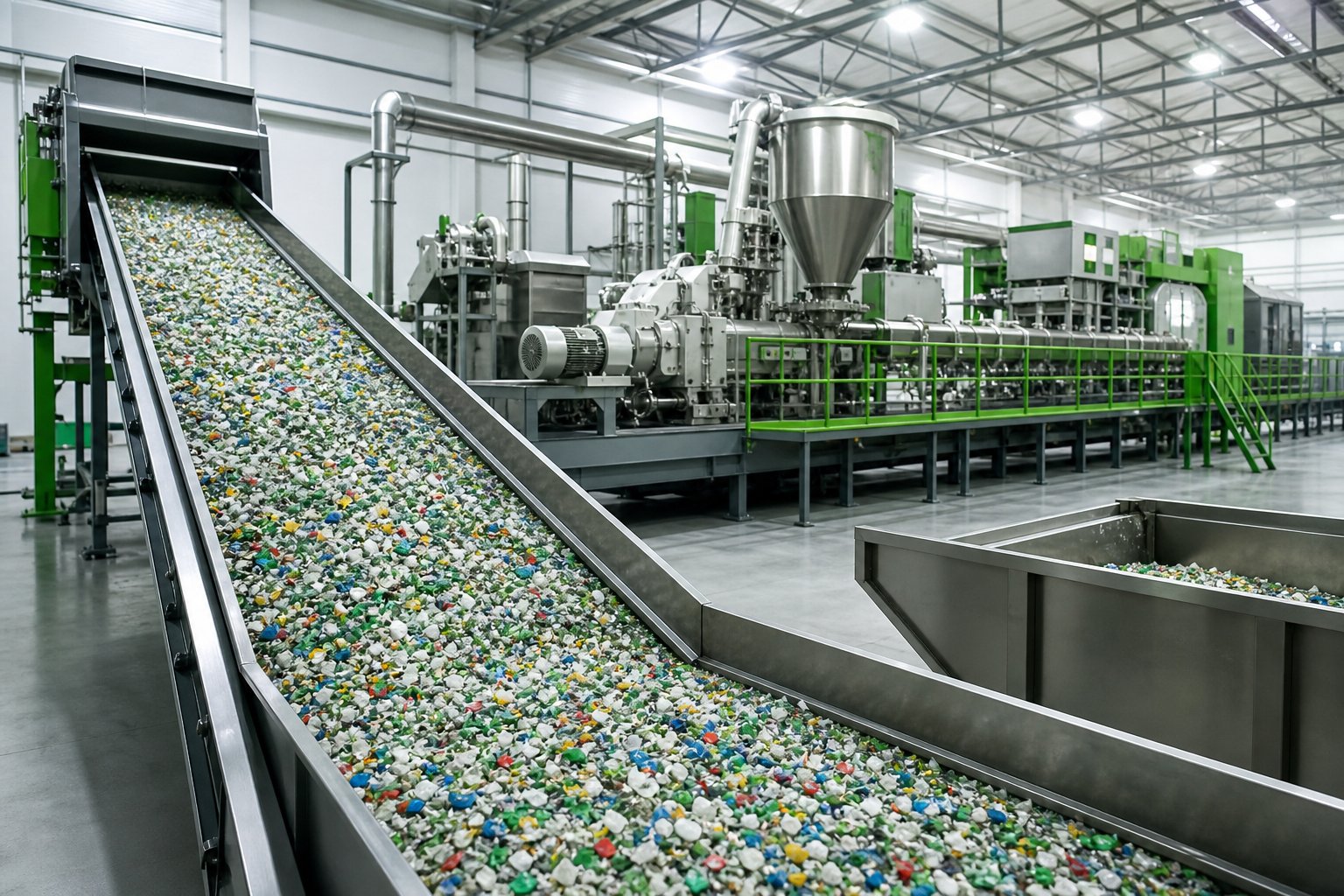
The plastics recycling industry has a material problem — literally. Post-consumer waste streams arrive at processing facilities as unpredictable mixtures of polymer types, contamination levels, moisture content, and degradation states. A bale of curbside HDPE might contain residual PP, traces of PET, paper label adhesives, food residue, and pigment systems from a dozen different manufacturers. Intermeshing co-rotating compounders, optimized for consistent virgin feedstocks with tight viscosity specifications, struggle with this variability. The tight clearances amplify the effects of contaminants, and viscosity mismatches between mixed polymer phases create torque spikes that force operators into conservative feed rates and frequent shutdowns.
Non-intermeshing designs handle this chaos more gracefully. The open-channel geometry tolerates foreign particles, variable melt viscosities, and inconsistent moisture levels without the surge behavior that plagues intermeshing machines processing off-spec material. The lower shear environment protects polymer chains that have already been through at least one thermal processing cycle — chains that cannot afford the additional molecular weight loss that high-intensity mixing inflicts. For recycling operations processing mixed-color post-consumer regrind, contaminated industrial film scrap, or multi-polymer shredded streams, this forgiving processing character translates directly into higher throughput consistency and fewer rejected batches.
Mechanochemical recycling approaches — where mechanical energy drives chemical modification of recycled polymers without solvents — are further expanding the relevance of twin screw platforms in recycling. While intermeshing machines dominate reactive extrusion for virgin resins, the gentler mechanical activation available in non-intermeshing systems is drawing attention for compatibilization of mixed recycled streams where controlled radical formation improves blend performance without triggering runaway degradation hydrolysis of already-weakened polymer chains.
Biodegradable polymer processing represents the second major growth vector. Materials like polylactic acid (PLA), polybutylene succinate, and lactid-based copolymers share a common vulnerability: they degrade rapidly under excessive thermal and mechanical stress. PLA in particular presents a compounding challenge because its semicrystalline structure depends on carefully managed nucleation crystallization behavior during processing. High shear disrupts the crystallization kinetics, producing amorphous regions that increase pla creep susceptibility under sustained loading — a critical failure mode in packaging and agricultural film applications where long-term dimensional stability matters.
Non-intermeshing processing preserves the molecular architecture that controls these downstream properties. The lower viscous dissipation keeps melt temperatures within the narrow window where PLA maintains chain integrity without triggering the rapid hydrolytic degradation that converts useful polymer into brittle, low-molecular-weight material. Similar benefits apply to polytrimethylene terephthalate and polyethylene naphthalate — specialty polyesters valued for their barrier properties and thermal resistance, but sensitive to the chain scission that aggressive extrusion conditions accelerate.
Even engineering thermoplastics benefit in specific scenarios. Polycarbonate, for example, is notoriously susceptible to stress-related failures during and after processing. Excessive residual stress from high-shear compounding increases the risk of polycarbonate cracking in end-use applications, particularly when parts encounter chemical agents or elevated temperatures in service. Compounding polycarbonate blends through a non-intermeshing system reduces the internal stress state of the melt, producing pellets that carry less "processing memory" into downstream molding operations.
The same characteristics that once positioned non-intermeshing twin screw technology as a specialized niche — lower shear, gentler thermal history, broader residence time distribution — now align precisely with the material-preservation priorities driving modern recycling, biodegradable polymer processing, and sustainable manufacturing.
Performance Optimization and Troubleshooting Tips
Recognizing the technology's potential is one thing. Extracting consistent, high-quality output from it day after day is another. Non-intermeshing extruders, like any processing equipment, develop operational issues that erode performance if left unaddressed. The difference is that troubleshooting these machines requires understanding the drag-flow mechanics that drive them — solutions borrowed from intermeshing troubleshooting guides often miss the mark entirely.
Here is a prioritized troubleshooting checklist covering the most common operational challenges, ordered from the issues you should investigate first to those that typically require more invasive intervention:
- Verify feed consistency before adjusting anything else. Inconsistent output is the most common complaint in non-intermeshing operations, and the root cause is frequently upstream of the extruder itself. Variations in feedstock bulk density, particle size distribution, or moisture content create irregular fill levels in the open screw channels. Check hopper flow patterns for bridging or rat-holing, confirm gravimetric feeder calibration, and ensure pre-drying systems are maintaining target moisture levels — especially for hygroscopic materials like PLA, nylons, and recycled PET flake.
- Optimize the barrel temperature profile to match your conveying mechanism. Because drag flow depends on friction between the polymer and the barrel wall, barrel temperature directly affects conveying efficiency. A barrel zone set too hot reduces polymer-to-wall friction as the material softens prematurely, causing slip and output loss. A zone set too cold increases torque demand and risks incomplete melting. Map your temperature profile in 5-degree increments across the feed and transition zones until you find the gradient that maximizes throughput at stable torque — this "friction tuning" step is far more critical in non-intermeshing systems than in intermeshing machines where positive displacement handles transport regardless of wall friction.
- Adjust screw speed to balance throughput against mixing quality. Higher RPM increases drag-flow conveying rate but reduces residence time and can outrun the distributive mixing that the inter-screw transfer zone provides. If you are seeing unmixed components or color streaks in the extrudate, reduce screw speed by 10 to 15 percent and evaluate whether the improved mixing compensates for the throughput reduction. In many cases, the answer is yes — and the reduced reject rate more than offsets the volume loss.
- Manage surging by synchronizing feed rate with screw speed. Surging — rhythmic fluctuations in die pressure and extrudate dimensions — typically indicates that the feed rate and screw conveying rate are out of balance. In starve-fed non-intermeshing systems, the fix is straightforward: reduce feed rate until pressure oscillations dampen below acceptable limits, then gradually increase until you find the maximum stable feed point. Flood-fed systems require more nuanced adjustment, often involving changes to the feed throat cooling to prevent premature melting and bridging at the entry point.
- Evaluate screw element selection for your specific formulation. Non-intermeshing systems offer unusual flexibility in screw profile design because the screws operate independently of each other geometrically. If mixing quality is insufficient, consider installing screw elements with shallower flights or reduced pitch in the mixing zone to increase material residence and shear exposure in that region — without affecting conveying behavior upstream. Staggering the screw element configurations between the two screws (using different flight starts or mismatched pitch zones) is a technique documented in research but underutilized in industry, and it offers a pathway to improved mixing performance without the capital expense of upgrading to an intermeshing machine.
- Inspect barrel and screw wear before concluding that process settings are the problem. If optimization of feed rate, temperature, and screw speed fails to resolve output inconsistencies, progressive wear is the likely culprit. Worn barrel liners and eroded flight tips degrade the frictional balance that drag-flow conveying depends on. Follow the bore gauge measurement and flight tip clearance inspection protocol outlined in the maintenance section, and trend the data against your baseline measurements.
- Pair optimized process settings with high-quality barrel and screw components. Even perfectly tuned process parameters cannot compensate for worn-out hardware. Stable conveying and consistent melt quality in demanding applications — masterbatch production at high filler loadings, plastic pelletizing of recycled streams, color-critical compounding runs — require barrel liners engineered for the specific wear environment. Suppliers like NANHAIYA offer parallel twin screw barrels designed for high-wear processing conditions, with liner metallurgy options that match the abrasion profiles of different material classes. Investing in properly specified replacement components is the most reliable way to lock in the process stability that optimization work achieves.
A recurring theme runs through every item on this list: non-intermeshing systems are more sensitive to the balance between feedstock, barrel condition, and temperature profile than intermeshing machines because they lack the forced positive-displacement transport that masks these variables in meshing designs. That sensitivity is not a weakness — it is a feature. It means the machine responds predictably to tuning inputs, and systematic optimization produces reliable, repeatable results.
The broader trajectory is clear. As the recycling industry scales, as biodegradable polymers move from niche to mainstream, and as material-preservation priorities continue displacing the "shear it harder" philosophy of previous decades, non-intermeshing twin screw extrusion is not fading — it is finding its moment. Engineers who understand the physics, select the right configuration, maintain the hardware, and optimize the process will find that this technology delivers exactly what modern processing demands: gentle handling of difficult materials, forgiving tolerance of variable feedstocks, and consistent output quality built on solid engineering fundamentals rather than brute mechanical force.
Frequently Asked Questions About Non Intermeshing Twin Screw Extruders
1. What is the difference between intermeshing and non intermeshing twin screw extruders?
In an intermeshing twin screw extruder, the flights of one screw engage with the channels of the other, creating positive displacement pumping and high shear forces. In a non intermeshing design, a deliberate gap separates the two screws so their flights never overlap. This means material transport relies on drag flow — friction between the polymer and barrel wall — rather than forced displacement. The practical result is significantly lower shear intensity, reduced viscous heat generation, and an open-channel architecture that allows free material transfer between the two screws. Non intermeshing machines excel with heat-sensitive polymers, high-filler compounds, and devolatilization processes, while intermeshing designs are preferred for high-intensity dispersive mixing and reactive extrusion.
2. What materials are best suited for non intermeshing twin screw extrusion?
Non intermeshing extruders are ideal for materials with narrow thermal processing windows or sensitivity to mechanical degradation. PVC — both rigid and flexible formulations — is the most common application because the gap between its melting point and decomposition temperature is dangerously small. Rubber compounds (EPDM, SBR, natural rubber), biodegradable polyesters like polybutylene succinate and PLA, polyphenyl ether blends, and thermoplastic elastomers all benefit from the gentler processing conditions. High-filler compounds loaded with 60-80% CaCO3 or talc also perform well because the open screw geometry avoids the pressure spikes that cause filler re-agglomeration in intermeshing machines. Recycled polymer feedstocks with variable contamination and mixed-polymer compositions are another growing application area.
3. How does a non intermeshing twin screw extruder achieve lower shear than intermeshing designs?
Shear rate depends on velocity gradients across the polymer melt. In intermeshing extruders, the highest shear occurs at the intermesh zone where one screw's flight passes through the other's channel, compressing material into extremely narrow clearances. Non intermeshing machines eliminate this zone entirely. The only significant shear-generating clearance is the overflight gap between each screw tip and the barrel wall. The space between the two screws remains wide and open, producing much lower velocity gradients. This reduction in shear directly decreases viscous dissipation — the conversion of mechanical energy into heat — resulting in lower peak melt temperatures and a gentler overall thermal history throughout the extrusion process.
4. When should I choose a non intermeshing twin screw extruder over a single screw extruder?
Both machine types rely on drag-flow conveying and produce relatively low shear, but non intermeshing twin screws offer superior distributive mixing through their open inter-screw material transfer zone. Choose a non intermeshing twin screw when your process requires blending additives, distributing colorants, or incorporating liquid components into the melt — tasks that exceed a single screw's limited mixing capability. Non intermeshing machines also handle a wider range of feedstock bulk densities and deliver better devolatilization efficiency thanks to broader residence time distribution. A single screw remains the better choice when the extruder simply needs to melt pre-compounded material and generate die pressure, since it offers lower capital cost and simpler maintenance.
5. What are the main maintenance concerns for non intermeshing twin screw extruders?
Non intermeshing extruders eliminate screw-to-screw contact wear, which is the most aggressive wear mechanism in intermeshing machines. However, barrel inner wall abrasion remains a primary concern because drag-flow conveying concentrates frictional forces on the barrel liner. Wear is most severe in the feed zone (where solid particles grind against the wall), filler incorporation zones (where abrasive minerals score the surface), and the discharge end (where screw deflection pushes flight tips into the barrel bore). Key maintenance practices include regular bore diameter measurement every 2,000-8,000 hours depending on compound abrasiveness, flight tip clearance checks, melt temperature trending, and throughput-at-speed tracking. Selecting replacement barrels with wear-resistant liner metallurgy — such as those offered by NANHAIYA's Parallel Twin Screw Barrel line at nhyscrews.com — is critical for minimizing unplanned downtime in high-wear applications.
Written by
Nanhaiya Technical Team
Zhoushan Nanhaiya Plastic Machinery Co., Ltd.
The Nanhaiya technical team supports screw and barrel manufacturing projects through application review, technical communication, custom manufacturing coordination, and production and quality control.
Discuss Your Application
Related Articles
More insights on screw barrel technology and plastics processing.
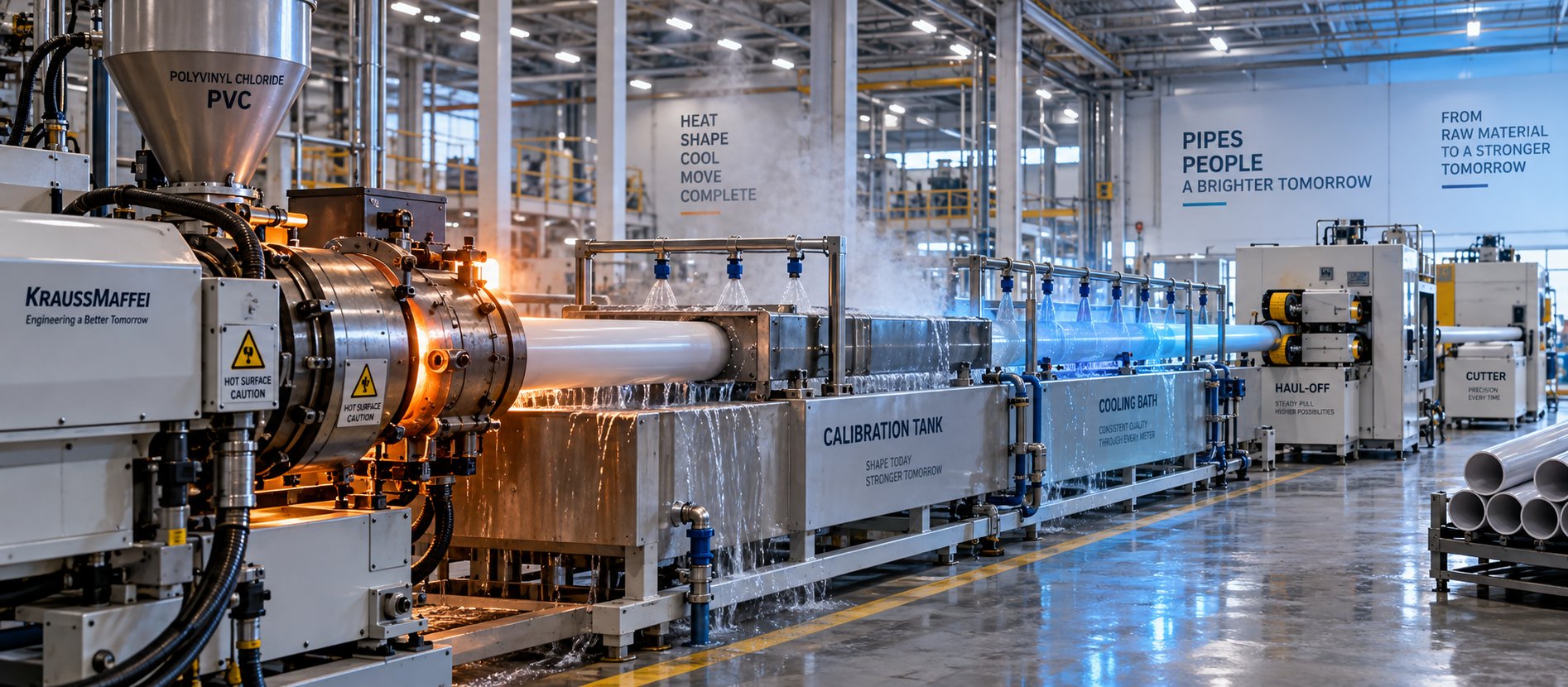
PVC Pipe Making Machine: What No Supplier Will Tell You First
Oct 21, 2026
Learn what a PVC pipe making machine really includes, how each component works, extruder types compared, maintenance schedules, defect fixes, and buying tips.
Read Article
What Your Film Extrusion Machine Datasheet Won't Tell You
Oct 20, 2026
Film extrusion machine guide covering blown vs cast processes, multilayer configurations, screw specs, resin selection, and supplier evaluation for production engineers.
Read Article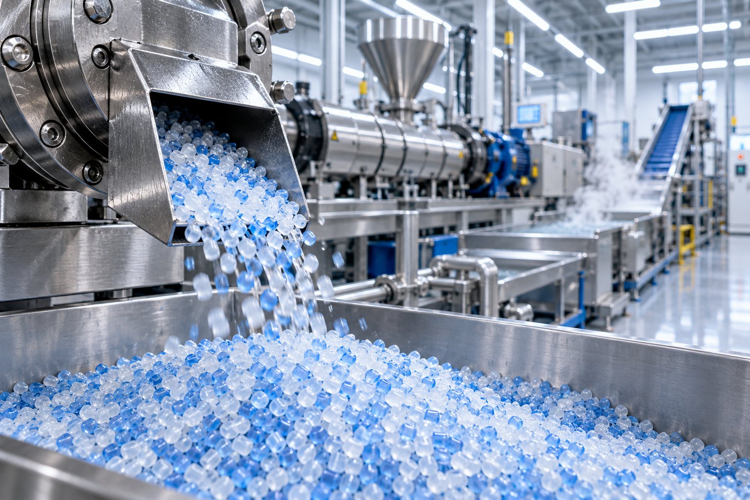
Raw Scrap to Perfect Pellets: Plastic Pelletizing Machine Guide
Oct 19, 2026
Learn how a plastic pelletizing machine converts scrap into uniform pellets. Covers cutting methods, extruder types, quality control, costs, and maintenance.
Read ArticleLooking for something else?
Search by material, symptom or product and jump straight to the relevant page.
These are navigation suggestions based on keyword matching — not a quotation, not a delivery commitment, and not a substitute for engineering review. Final specification is confirmed by our engineers against your drawings and processed material.
Need help with screw barrel selection?
Share your machine model, processed material and application. Our team can help with pricing and technical support.