

What Makes Planetary Roller Screws Different and Why Manufacturing Matters
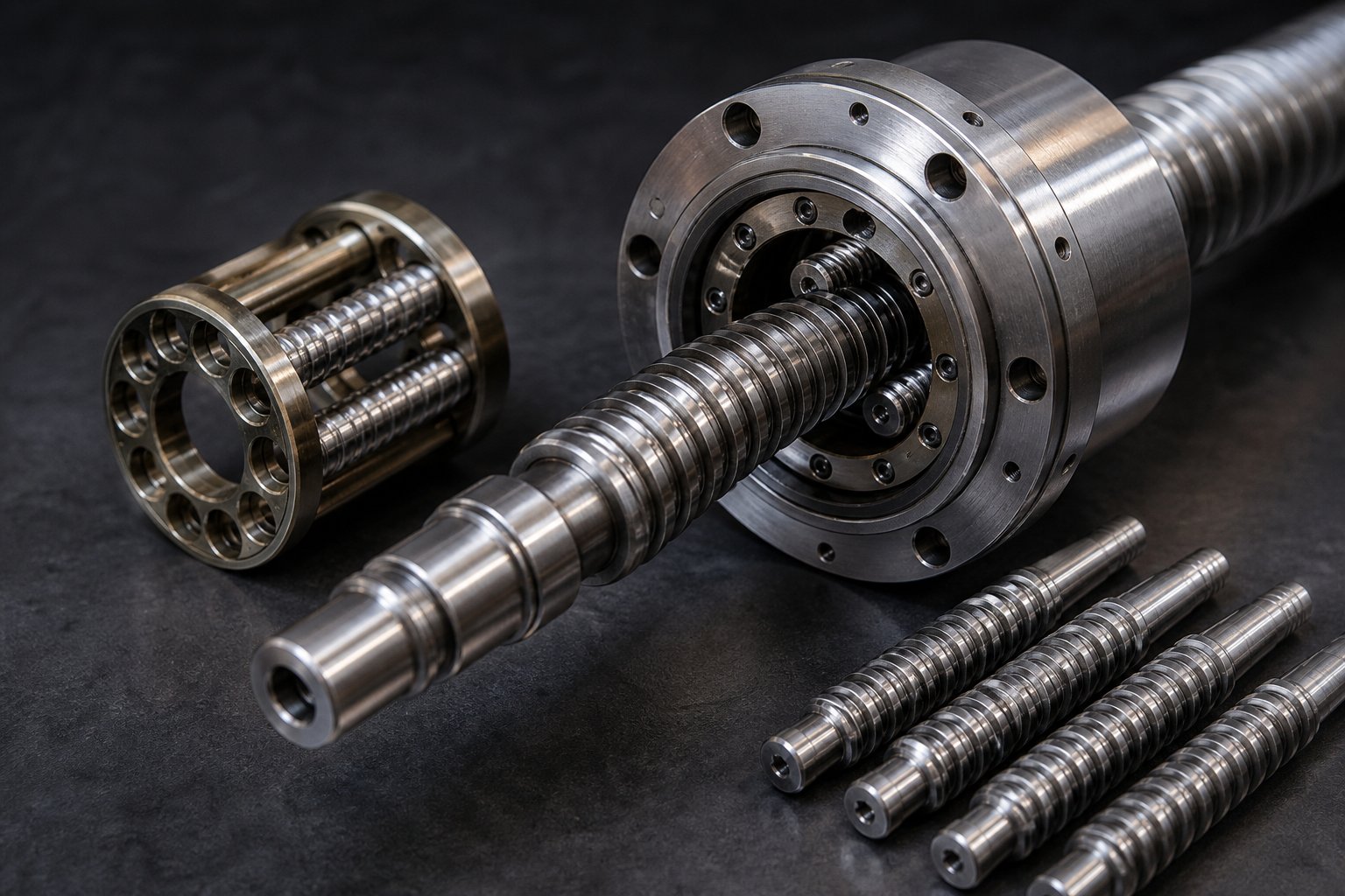
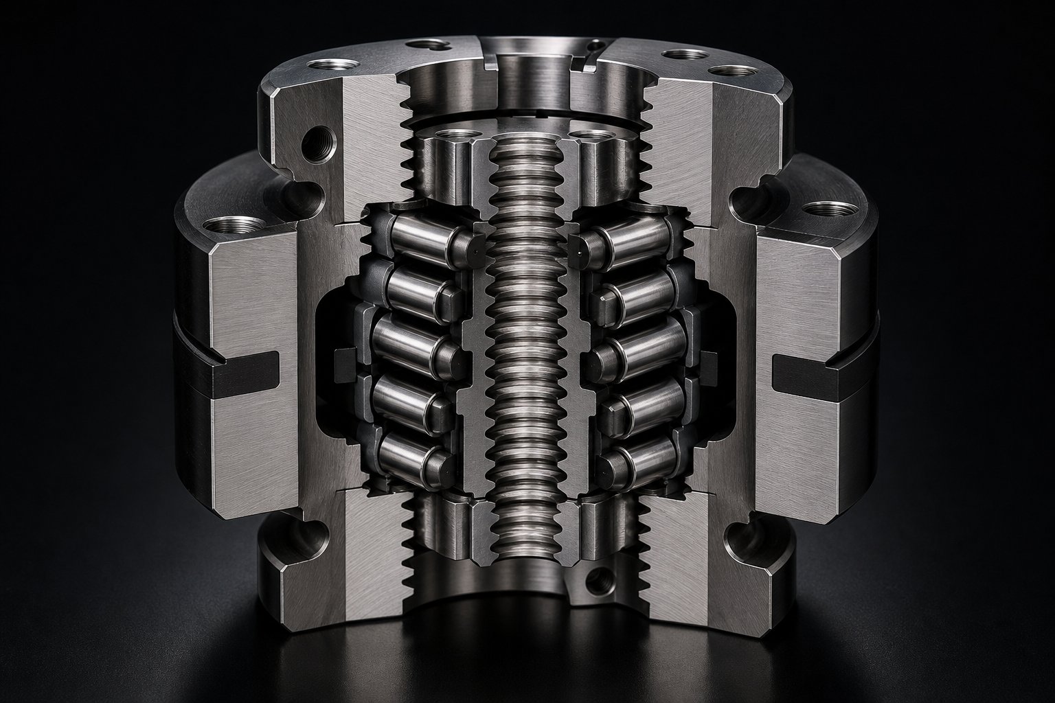
A planetary roller screw is a mechanical linear actuator in which multiple threaded rollers orbit a central screw shaft inside a threaded nut, converting rotary motion into precise linear travel. Imagine a miniature solar system: the screw shaft sits at the center, small threaded rollers circle around it like planets, and a nut encases the entire assembly, translating smoothly along the shaft's axis. This elegant arrangement is what gives the device its name — and its extraordinary load-carrying ability.
What separates planetary roller screws from the more common ball screw? It comes down to contact geometry. Ball screws transmit force through steel balls making point contact with their raceways. Planetary roller screws, by contrast, use threaded rollers that make line contact along the shaft and nut threads simultaneously. That line contact distributes force across a far greater surface area, enabling higher load ratings in a more compact envelope. However, this advantage comes at a cost: manufacturing tolerances become orders of magnitude more critical because every thread flank on every roller must mesh with the shaft and nut in near-perfect unison.
How a Planetary Roller Screw Converts Motion
The kinematic principle is surprisingly intuitive. When the screw shaft rotates, the threaded rollers — held in a fixed angular pattern by a carrier cage — orbit the shaft while simultaneously spinning on their own axes. This planetary motion forces the nut to translate linearly along the shaft. The result is a planetary roller screw actuator capable of converting high-speed rotation into powerful, controlled linear force with minimal friction and exceptional stiffness.
Four primary components form the structural backbone of every planetary roller screw assembly:
- Screw shaft — the central threaded element that receives rotary input
- Threaded rollers — multiple small cylinders with matching thread profiles that orbit the shaft
- Nut — the internally threaded outer housing that translates linearly
- Roller carrier (cage) — the component that maintains equal angular spacing between rollers and prevents contact between them
Each of these parts demands its own specialized manufacturing sequence — and the precision achieved in one directly affects the performance of the others.
Why Manufacturing Precision Defines Roller Screw Performance
Because load is shared across many simultaneous thread contacts, even a single-digit micrometre deviation in one roller can cascade through the assembly. The result? Uneven load sharing, accelerated wear on overloaded threads, and a measurable drop in dynamic capacity. Precision manufacturers target shape and position tolerances in the single-digit µm range and surface finishes of Ra 0.4 — numbers that demand grinding processes far beyond what conventional machining can deliver.
This guide walks through every manufacturing stage — from raw steel selection and blank preparation through heat treatment, thread grinding, surface finishing, assembly, and final inspection. It is designed to fill a gap no single existing resource covers comprehensively, giving engineers and procurement teams a complete framework for understanding how each process step shapes the performance and lifespan of the finished assembly.
The journey begins where every high-performance component begins: with the steel itself.
Raw Material Selection and Steel Grade Specifications
Every micrometre of final precision in a planetary roller screw is either enabled or limited by the steel billet it started as. Material selection is not simply a purchasing decision — it is the first manufacturing decision, one that directly constrains how the component responds to turning, heat treatment, grinding, and ultimately years of cyclic loading in service. Choose the wrong grade, and no amount of downstream process refinement can compensate.
Steel Grades Used for Screw Shafts and Rollers
Screw shafts and threaded rollers experience the highest contact stresses in the assembly, so they demand bearing-grade steels engineered for rolling contact fatigue. Two families dominate the landscape:
- Through-hardening steels — AISI 52100 (known as 100Cr6 in European designation) is the workhorse. Its high carbon content allows uniform hardness throughout the cross-section after quenching and tempering, producing a fine-grain martensitic microstructure with excellent wear resistance.
- Case-hardening steels — Grades like 16MnCr5 and 20MnCr5 are carburized to produce a hard, wear-resistant surface layer over a tough, ductile core. This combination is particularly valuable for larger-diameter shafts where through-hardening risks creating brittle sections or uneven hardness gradients.
Why these specific grades? They share three characteristics that matter at every downstream manufacturing stage: high fatigue resistance under cyclic Hertzian contact, a fine-grain microstructure after heat treatment that supports consistent surface finishes during grinding, and predictable hardenability that ensures repeatable results across production batches.
| Steel Grade | Carbon Content Range | Typical Hardness After Heat Treatment | Best Suited Component | Key Advantage |
|---|---|---|---|---|
| AISI 52100 / 100Cr6 | 0.93 – 1.05% | 58 – 62 HRC | Screw shafts, rollers (small to mid-size) | Uniform through-hardness, superior rolling contact fatigue life |
| 16MnCr5 | 0.14 – 0.19% | 58 – 62 HRC (case), 30 – 40 HRC (core) | Large-diameter screw shafts | Hard surface with shock-absorbing tough core |
| 20MnCr5 | 0.17 – 0.22% | 58 – 62 HRC (case), 32 – 42 HRC (core) | Shafts and rollers under high dynamic loads | Deeper case depth capability, excellent core toughness |
| AISI 440C | 0.95 – 1.20% | 56 – 58 HRC | Shafts and rollers for corrosive environments | Corrosion resistance (martensitic stainless) |
| AISI 304L | ≤ 0.03% | Not heat-hardenable (austenitic) | Nuts, housings in hygienic applications | Excellent corrosion resistance, FDA-compliant surface |
Material Considerations for the Nut and Carrier Cage
The nut and carrier cage face different stress regimes than the shaft and rollers, so they often call for different materials. Nuts may use the same bearing steels as the shaft — especially in high-load or high-precision assemblies — but lower-load designs sometimes substitute bronze alloys. Bronze offers natural lubricity and excellent compatibility with marginal lubrication strategies, reducing friction at the thread interface when oil supply is intermittent.
Carrier cages, on the other hand, prioritize low mass and smooth roller guidance over raw strength. Metal cages are typically stamped from lightweight steel alloys, while lower-load or high-speed applications increasingly use engineered polymers such as PEEK or glass-filled nylon. The tradeoff is straightforward: metal cages offer higher structural rigidity under dynamic loads, while polymer cages reduce inertia, dampen vibration, and eliminate the risk of metal-on-metal contact between the cage and rollers.
Here is the critical insight engineers sometimes overlook: material choice does not just affect the finished component's performance — it shapes every manufacturing step along the way. A steel's carbon content and alloy composition dictate its machinability during rough turning, its dimensional response to heat treatment (how much it grows, shrinks, or distorts during quenching), its grindability during finish operations, and ultimately the contact fatigue life achievable in service. Selecting a material without considering these downstream interactions is like choosing an ingredient without knowing the recipe.
For specialty environments, the material question becomes even more complex. Roller screws for the food and beverage industry, pharmaceutical equipment, or marine applications often require stainless steel grades to resist corrosion and meet hygiene standards. Research on AISI 304L in food processing highlights that surface roughness below Ra 0.5 micrometres is considered "clean" for hygienic applications, and the material's passive chromium oxide layer provides the corrosion protection these environments demand. Yet stainless grades introduce real manufacturing headaches: lower machinability means slower cutting speeds, higher tool wear, and greater difficulty achieving tight tolerances during turning. Their different heat-treatment protocols — austenitic stainless steels like 304L cannot be through-hardened at all — force designers to rethink the entire process chain, sometimes requiring alternative surface-hardening techniques such as nitriding or specialized coatings to achieve adequate wear resistance.
The material specified on a drawing, then, is never just a material. It is a manufacturing roadmap — one that determines what machines are needed, what cycle times are achievable, and what final tolerances are realistic. With that roadmap established, the next critical challenge is shaping the raw steel into the most geometrically demanding component in the assembly: the screw shaft and its precision thread.
Screw Shaft Fabrication From Blank to Precision Thread
The screw shaft is the central axis of every planetary roller screw — the component around which rollers orbit, the nut translates, and the entire load path converges. Its geometry must be so precise that every thread flank simultaneously engages multiple rollers under load without favoring one contact line over another. Achieving that level of uniformity requires a carefully sequenced fabrication process where each stage builds on the last, and any shortcut compounds into a measurable performance loss downstream.
Rough Machining and Blank Preparation
Fabrication starts with bar stock. The selected steel — whether AISI 52100, 16MnCr5, or a stainless variant — arrives as round bar, typically hot-rolled or cold-drawn depending on the diameter and grade. The first operation is straightforward: cut the bar to length with sufficient material allowance for all subsequent operations.
From there, the blank moves to a CNC lathe for rough turning. The goal here is not precision — it is geometry. Rough turning establishes the basic cylindrical profile: stepped diameters for bearing journals, shoulders, and thread zones. Machinists leave deliberate machining allowances on every critical surface, typically several tenths of a millimetre beyond the final dimension. These allowances exist for one reason: to give the finish grinding stage enough material to correct the minor distortions that heat treatment will inevitably introduce.
Why does rough machining always precede heat treatment? The answer is practical. Once steel is hardened to 58–62 HRC, it becomes extraordinarily resistant to material removal. Attempting to remove bulk material from a through-hardened shaft would destroy cutting tools, generate excessive heat, and risk surface damage. As shaft machining process research confirms, the proper sequence is rough machining while the steel is still soft and machinable, heat treatment to achieve target hardness, and then finish grinding to bring dimensions into final tolerance. Reversing this order would be physically impractical or prohibitively expensive.
Several details during blank preparation deserve attention:
- Center drilling — center holes are often drilled at both ends of the shaft blank to provide repeatable reference points for turning and grinding between centers. For long shafts, these centers are critical for controlling runout and concentricity across the full length.
- Stock distribution — uneven rough-turning stock leads to variable cutting loads during finish operations, potentially causing taper, chatter, or localized overheating. Consistent allowance across all surfaces prevents these issues.
- Straightness verification — especially for shaft diameters below 20 mm or length-to-diameter ratios above 10:1, incoming bar straightness should be checked. A bent blank produces a bent shaft, and no amount of grinding corrects a fundamental bow that exceeds the available stock allowance.
Think of blank preparation as setting the foundation of a building. You are not constructing the final structure yet — you are ensuring that the ground beneath it is level, stable, and properly measured. Every deviation at this stage amplifies through heat treatment and into the grinding room.
Thread Generation on the Screw Shaft
Thread generation is where the screw shaft transforms from a simple cylinder into the precision component that defines the entire assembly's accuracy class. This is the most technically demanding machining operation in the planetary roller screw manufacturing chain, and the method selected here determines the achievable tolerance, surface finish, production speed, and ultimately the unit cost.
Four primary methods are available, each suited to different precision requirements and production contexts:
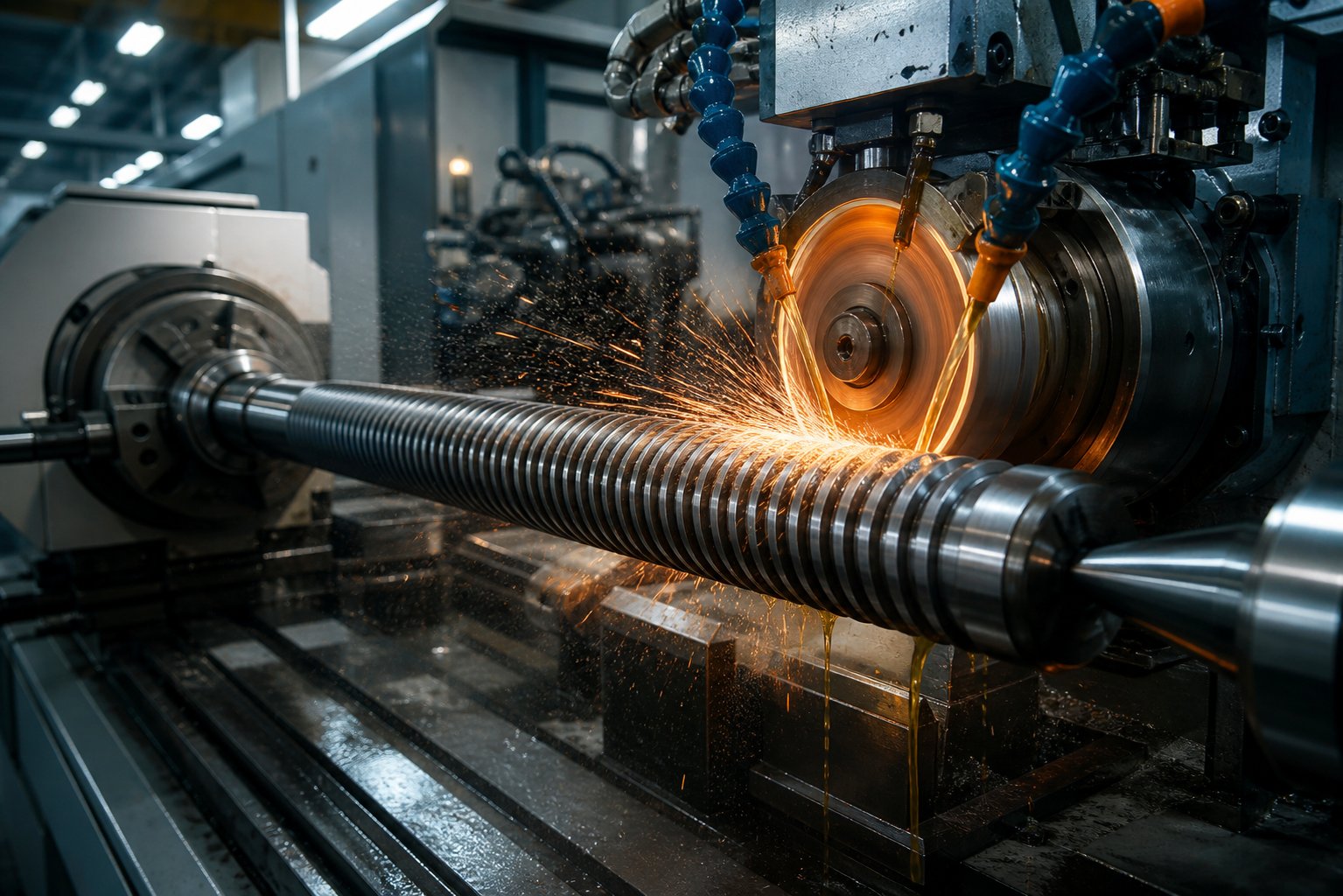
Thread grinding delivers the highest precision. A profiled grinding wheel — typically CBN (cubic boron nitride) or diamond — traverses the shaft, generating the thread form one pass at a time. Thread grinding achieves accuracy classes up to IT1 and surface finishes in the Ra 0.2–0.4 range. It is the only method capable of producing the tight geometric constraints demanded by Gothic arch thread profiles, where the contact geometry between roller and shaft requires sub-micrometre form accuracy. The tradeoff is speed: thread grinding is inherently slow and requires expensive, dedicated equipment.
Thread whirling uses a ring of cutting inserts that surrounds the workpiece. As the shaft rotates slowly, the whirling head spins at high speed, cutting the thread profile with a series of rapid, light passes. This method is particularly efficient for long-lead screws where the thread helix requires substantial axial travel per revolution. Whirling achieves moderate precision — generally in the IT5–IT7 range — and is significantly faster than grinding, making it a strong choice for production volumes where grinding would create bottlenecks.
Thread milling uses a rotating multi-tooth cutter that follows a helical toolpath programmed on a CNC machining center. It offers good flexibility — a single machine can produce different thread pitches and profiles through programming changes alone — and delivers cost-effective results for moderate precision requirements. Thread milling typically achieves IT5–IT8 accuracy and is often used for prototype or low-volume production where investing in dedicated grinding setups is not justified.
Thread rolling takes a fundamentally different approach: instead of removing material, it displaces it. Hardened dies press the thread form into the shaft surface through plastic deformation. This cold-forming process work-hardens the thread flanks, improving surface hardness and fatigue resistance. It is fast and material-efficient — but it is generally limited to standard thread profiles and lower accuracy classes. For planetary roller screws requiring Gothic arch profiles or single-digit micrometre tolerances, rolling alone cannot achieve the required form accuracy. However, recent advances in cold-forming technology for precision screw threads are closing this gap in certain applications, with some manufacturers reporting cycle time reductions from minutes to seconds compared to traditional grinding.
| Method | Achievable Tolerance Class | Surface Finish Range (Ra) | Production Speed | Best Application Context | Relative Cost |
|---|---|---|---|---|---|
| Thread Grinding | IT1 – IT3 | 0.2 – 0.4 µm | Slow | High-precision planetary roller screws, Gothic arch profiles | High |
| Thread Whirling | IT5 – IT7 | 0.4 – 1.6 µm | Moderate to Fast | Long-lead screws, medium-precision production runs | Moderate |
| Thread Milling | IT5 – IT8 | 0.8 – 3.2 µm | Moderate | Prototyping, low-volume, flexible production | Low to Moderate |
| Thread Rolling | IT7 – IT9 | 0.4 – 1.6 µm | Very Fast | Standard profiles, high-volume lower-precision variants | Low |
The thread profile itself — not just the diameter or pitch — is what ultimately dictates which method a manufacturer must use. Standard triangular profiles are geometrically simpler and can be produced by any of the four methods. Gothic arch (ogival) profiles, however, feature a complex curvature that creates four-point contact geometry between the roller and shaft threads. This curvature demands grinding because the form tolerance on each flank is so tight that milling and rolling simply cannot hold the required shape consistency across the full thread length.
Consider the dimensional range these processes must accommodate. Shaft diameters for planetary roller screws span from as small as 3.5 mm to as large as 210 mm, with leads ranging from 1.0 mm to 50 mm. That is an enormous envelope of dimensional variety — a single manufacturing facility producing these components must maintain tooling, fixtures, and grinding wheels for dozens of size combinations, each requiring its own setup parameters. A 5 mm diameter shaft fixtured in a precision collet for thread grinding bears almost no resemblance to a 200 mm shaft supported between centers on a large cylindrical grinder, yet both demand the same micrometre-level thread form accuracy.
This dimensional diversity also explains why many manufacturers specialize in specific size ranges. The fixturing challenges, machine rigidity requirements, and thermal management strategies differ so significantly between small and large diameters that mastering both requires substantial capital investment and deep process expertise.
With the screw shaft's precision thread established, the manufacturing challenge shifts to an even more demanding scale: producing the miniature threaded rollers that must match this thread profile with absolute fidelity — at diameters often measured in single-digit millimetres.
Threaded Roller and Carrier Cage Production
If the screw shaft is the heart of a planetary roller screw, the threaded rollers are its circulatory system — and the carrier cage is what keeps every vessel in place. These two components represent the most intricate manufacturing challenges in the entire assembly. The rollers must replicate the shaft's thread profile at a fraction of its scale, while the cage must position each roller with absolute uniformity under dynamic orbital loads. Getting either one wrong undermines everything the precision shaft was built to deliver.
Threaded Roller Manufacturing Challenges
Picture threading a cylinder that is barely wider than a pencil lead. Threaded rollers in a planetary roller screw are miniature cylinders — often just 3 to 8 millimetres in diameter — that must carry a thread profile matching the screw shaft with extreme geometric fidelity. Every flank angle, every pitch interval, every root radius on the roller must correspond to its counterpart on the shaft within single-digit micrometre tolerances. At this scale, manufacturing difficulties multiply rapidly.
The fundamental problem is fixturing. A 6 mm diameter roller cannot be clamped between conventional lathe centers without risking deflection, distortion, or outright damage. Even modest cutting forces at this scale can push the workpiece off-axis, introducing taper and runout errors that cascade into uneven load sharing once the roller is assembled. The smaller the roller, the more this problem intensifies.
The typical manufacturing process follows two primary stages:
Stage 1: Blank preparation on CNC Swiss-type lathes. The roller blank starts as bar stock, fed through a CNC Swiss-type lathe where a guide bushing supports the workpiece immediately adjacent to the cutting point. This close support is critical — it minimizes the unsupported length of the bar, dramatically reducing deflection and chatter on small-diameter parts. Swiss-type turning establishes the roller's outer diameter, end faces, and any chamfers or relief features, holding turning tolerances as tight as ±0.02 mm. For parts in the single-digit millimetre range, this guide-bushing approach is not optional — it is the only practical way to achieve repeatable precision on blanks this small.
Stage 2: Thread grinding on specialized small-diameter machines. After blank preparation and heat treatment, the thread profile is ground onto each roller using dedicated small-diameter thread grinding machines. These machines employ narrow, precisely profiled CBN or diamond grinding wheels that can access the tight helical geometry of a miniature thread. The grinding process must manage heat generation carefully — on a part this small, even minor thermal expansion can push the thread form outside tolerance. Controlled coolant flow and conservative feed rates are essential to prevent grinding burns and maintain dimensional stability.
Sounds expensive? It is. Thread grinding every roller in a production run demands significant machine time and operator skill. That is why some manufacturers turn to thread rolling for lower accuracy classes. In thread rolling, hardened dies press the thread form into the roller blank through plastic deformation rather than material removal. This cold-forming process is substantially faster and offers a real bonus: it work-hardens the roller surface, increasing surface hardness and fatigue resistance without additional heat treatment. For general-purpose planetary roller screws where tolerances in the IT7–IT9 range are acceptable, thread rolling delivers a cost-effective and mechanically sound alternative.
For high-precision variants — particularly those with Gothic arch thread profiles requiring sub-micrometre form accuracy on each flank — grinding remains the only viable method. The complex curvature of a Gothic arch profile cannot be consistently replicated through plastic deformation at roller-scale diameters, making ground threads the non-negotiable standard for premium assemblies.
Carrier Cage Design and Fabrication
Imagine removing the cage from a planetary roller screw and trying to operate it. The rollers, with nothing constraining their angular positions, would immediately cluster together, collide, and jam. The carrier cage is the unsung structural element that prevents this chaos — maintaining equal angular spacing between all rollers and ensuring that no roller ever contacts its neighbor during operation.
In functional terms, the cage rides between the screw shaft and the nut, with each roller seated in a precisely machined pocket. As the rollers orbit the shaft and spin on their own axes, the cage rotates with them, acting as a spacer frame that preserves the planetary geometry the entire mechanism depends on. In recirculating or inverted roller screw designs, the cage also guides rollers through their return path, making its dimensional accuracy even more consequential.
Manufacturing methods vary based on material and application demands:
Metal cages are produced through precision stamping for high-volume production or wire-EDM (electrical discharge machining) for complex pocket geometries and tighter tolerances. Stamping is faster and more economical, but wire-EDM offers superior dimensional control on the pocket walls and spacing — a tradeoff that mirrors the grinding-versus-rolling decision for the rollers themselves. Metal cages typically use lightweight steel alloys that balance structural rigidity with low rotational inertia.
Polymer cages are injection molded from engineered thermoplastics such as PEEK or glass-filled nylon. Molding enables complex geometries in a single operation and produces cages that are lighter, quieter, and inherently self-lubricating at the roller contact surfaces. However, polymer cages have lower structural rigidity under high dynamic loads, limiting their use to lower-load or high-speed applications where vibration damping and reduced inertia outweigh raw strength.
Regardless of the manufacturing method chosen, several quality attributes determine whether a cage elevates or undermines the performance of the finished assembly:
- Pocket spacing uniformity — unequal angular spacing between pockets means unequal roller distribution, which directly causes uneven load sharing and accelerated wear on overloaded rollers
- Surface finish on roller contact surfaces — rough pocket walls increase friction between the cage and rollers, generating heat, noise, and premature wear at every orbit
- Axial clearance control — too much clearance allows rollers to shift axially during operation, disrupting thread engagement; too little clearance binds the rollers and increases drag
- Structural rigidity under dynamic loads — the cage must resist deformation from centrifugal forces and roller reaction loads without flexing enough to alter pocket positions
You'll notice a pattern here: cage quality is not about the cage itself — it is about what the cage does to everything else. A cage with inconsistent pocket spacing creates a vibration signature that no amount of shaft or roller precision can compensate for. In noise-sensitive applications like humanoid robotics or medical positioning systems, cage manufacturing quality often becomes the limiting factor in acoustic performance. For recirculating designs, even minor pocket misalignment can disrupt the smooth roller return path, causing hesitation, increased friction, and eventually mechanical failure.
The rollers and cage, once manufactured and inspected, form a matched sub-assembly that will eventually unite with the screw shaft inside the nut — the internally threaded housing whose bore geometry presents its own set of precision-critical manufacturing demands.
Nut Manufacturing and Thread Profile Engineering
The nut is the outer housing of the planetary roller screw — the component that receives the cumulative force transmitted through every roller and converts it into usable linear output. Its internal thread must mesh with all rollers simultaneously, which means the bore geometry carries a tolerance burden unlike any other feature in the assembly. A shaft thread that deviates by a few micrometres affects one contact line at a time. A nut thread that deviates affects every roller at once.
Nut Bore Threading and Internal Geometry
Imagine trying to grind a precision thread inside a tube where your grinding wheel can barely fit, chips have nowhere to go, and heat builds faster than you can dissipate it. That is the reality of internal thread manufacturing for planetary roller screw nuts — and it is why EMAG identifies the nut as the most challenging component in the entire assembly.
The difficulty starts with proportions. A typical nut for robotic applications measures roughly 150 mm in total length with an inner diameter of approximately 20 mm, producing a length-to-diameter ratio of 7:1 or even 8:1. After heat treatment, the material hardness reaches 58-62 HRC — in some cases up to 65 HRC. Threading a long, narrow bore in steel that hard requires specialized equipment and exacting process control at every step.
Internal thread grinding is performed on dedicated machines using small-diameter CBN (cubic boron nitride) or diamond grinding wheels. CBN is the preferred abrasive for this application because it combines hardness second only to diamond with superior thermal stability and chemical compatibility with ferrous metals — critical properties when grinding hardened bearing steels like AISI 52100 at sustained contact temperatures. Diamond wheels, by contrast, chemically react with iron at grinding temperatures, making them unsuitable for this operation.
Three factors make internal threading inherently more difficult than the external thread grinding performed on screw shafts:
- Limited tool access — the grinding wheel diameter is constrained by the bore size, which limits the wheel's stiffness, surface speed, and abrasive volume. A smaller wheel wears faster, deflects more under load, and requires more frequent dressing to maintain profile accuracy.
- Swarf evacuation — chips and grinding debris generated inside a deep bore have no natural escape path. On horizontal machines, swarf accumulates in the bore, risking re-cutting and surface damage. Vertical machine designs — where gravity pulls chips downward and out of the bore — offer a significant advantage here, and high-pressure cutting fluid directed through the spindle helps flush debris reliably during series production.
- Thermal management — grinding generates heat concentrated in a confined space. With limited airflow and restricted coolant access deep in the bore, localized thermal expansion can distort the thread form mid-operation. Controlled feed rates and optimized coolant delivery are not optional refinements — they are fundamental process requirements.
The manufacturing process chain for a typical nut follows a tightly sequenced logic. Soft turning on both sides establishes the rough external and internal geometry while the steel is still machinable at 26-32 HRC. Heat treatment then hardens the component to its target 60+ HRC. Hard turning and CBN grinding correct heat-treatment-induced distortion on the outer diameter, which also establishes the precision reference surfaces for internal operations. Only then does the bore receive its final internal thread — first through precision boring and semi-finish turning to establish the near-net-shape thread form, and finally through internal thread grinding to achieve the finished dimensions and surface quality. In practice, pitch errors of less than 2 micrometres between individual thread turns are achieved through this final grinding pass.
The required surface roughness on the internal thread raceway is Ra 0.4, with roundness held to 0.025 mm or better and concentricity within 0.025 mm. These numbers define the quality envelope that separates a functional nut from one that introduces vibration, uneven roller loading, or premature wear into the assembled planetary roller screw.
Thread Profile Types and Their Manufacturing Implications
The thread profile machined into the nut — and correspondingly into the shaft and rollers — is not a secondary detail. It is arguably the single most consequential decision made at the intersection of design engineering and manufacturing engineering. Three main profile families exist, each carrying distinct manufacturing requirements and performance characteristics.
Standard triangular profiles are the simplest to manufacture. The V-shaped thread form can be produced by turning, milling, or grinding with relatively straightforward tooling and setup. Two-point contact geometry between the roller and nut thread flanks provides adequate load capacity for general-purpose applications — linear actuators, positioning systems, and moderate-duty industrial automation. Because the geometric constraints are less severe, triangular profiles tolerate wider manufacturing tolerances without significant performance degradation, keeping production costs lower and lead times shorter.
Gothic arch (ogival) profiles elevate both performance and manufacturing complexity. Instead of a simple V-shape, the thread flanks follow a precise radius that creates a four-point contact geometry — two contact points on each flank rather than one. This doubles the effective contact area under load, substantially increasing the screw's dynamic and static load ratings for a given size. However, that curved flank geometry demands extremely tight form tolerances. Even a slight deviation from the intended arc radius shifts the contact points, converting four-point contact into two-point or even single-point contact and negating the profile's entire load-capacity advantage. Grinding is the only viable manufacturing method for Gothic arch profiles because neither milling nor rolling can hold the required curvature consistency across the full thread length of the nut bore.
Custom profiles are engineered for specific load, speed, or stiffness regimes. These might include modified Gothic arch geometries with asymmetric flank radii optimized for predominantly one-directional loading, or profiles designed to favor lubricant retention in high-speed applications. Custom profiles demand custom grinding wheels dressed to proprietary shapes, specialized inspection fixtures, and often iterative development cycles that drive unit costs significantly higher than standard variants.
The thread profile chosen at the design stage locks in the manufacturing method, tolerance class, and ultimately the unit cost — making profile selection the single most consequential design-manufacturing intersection in the entire planetary roller screw development process.
This reality creates an important feedback loop that too few organizations take advantage of. When design engineers select a Gothic arch profile to maximize load capacity, they are simultaneously selecting internal thread grinding, sub-micrometre form tolerances, and CBN wheel costs that carry through to every nut produced. If manufacturing engineers are consulted early — during profile selection rather than after drawings are released — they can identify where a slight profile modification might reduce grinding passes by half, or where a specific tolerance relaxation on a non-critical flank region could shorten cycle times without measurable performance impact.
This design-manufacturing dialogue is where real cost optimization happens. Not in negotiating material prices or squeezing supplier margins, but in aligning the geometric intent of the design with the physical capabilities and economics of the grinding process. A well-chosen thread profile that accounts for manufacturing realities from the start will outperform an over-specified profile that forces compromises on the shop floor.
The nut, shaft, and rollers — with their thread profiles now defined and machined — are still only partway through their transformation. Each component remains in a state where its dimensional precision is established but its material properties are not yet optimized for service. That transformation happens in the furnace, where heat treatment fundamentally alters the steel's microstructure and unlocks the hardness, toughness, and fatigue resistance that precision grinding alone cannot provide.
Heat Treatment and Surface Finishing Processes
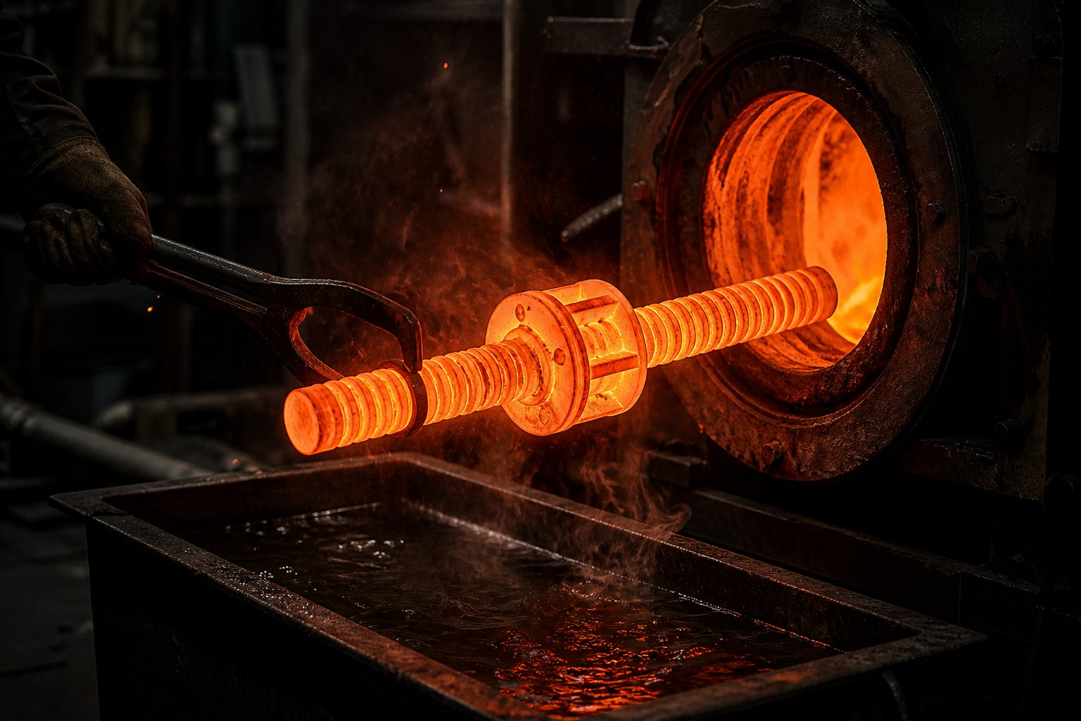
Steel that has been precisely machined is still, in a metallurgical sense, soft. The thread profiles ground into screw shafts, rollers, and nuts may be dimensionally perfect, but the material beneath them lacks the hardness to survive millions of load cycles without deformation, pitting, or fatigue failure. Heat treatment is the process that bridges this gap — it restructures the steel's crystalline lattice at the atomic level, converting relatively soft pearlite and ferrite into hard, wear-resistant martensite. Without it, even the most exquisitely machined planetary roller screw would fail catastrophically under service loads.
Yet heat treatment is also one of the most disruptive steps in the manufacturing chain. It introduces dimensional distortion that must be anticipated, accommodated, and corrected. Understanding why the process sequence is locked in a specific order — and what happens when it is not — is essential for anyone evaluating manufacturing quality.
Heat Treatment Sequences and Why Order Matters
Two primary heat treatment strategies dominate planetary roller screw production, each matched to a specific family of steels.
Through-hardening applies to high-carbon bearing steels like AISI 52100 (100Cr6). The component is heated to its austenitizing temperature — typically 830-860 degrees Celsius — soaked to achieve uniform temperature throughout the cross-section, then rapidly quenched in oil or polymer solution. This transforms the microstructure to martensite across the entire part, not just the surface. A subsequent tempering cycle at 150-180 degrees Celsius relieves internal stresses and fine-tunes the balance between hardness and toughness. The result: uniform hardness of 58-62 HRC from surface to core, ideal for the rolling contact fatigue conditions that screw shafts and rollers endure.
Case-hardening (carburizing) is the method of choice for lower-carbon alloy steels like 16MnCr5 and 20MnCr5. These grades cannot achieve sufficient hardness through direct quenching because they lack the carbon content to form hard martensite on their own. Instead, the components are placed in a carbon-rich atmosphere at 900-950 degrees Celsius for hours — sometimes tens of hours — allowing carbon atoms to diffuse into the surface layer. This carbon-enriched case is then quenched to achieve surface hardness of 58-62 HRC, while the low-carbon core remains tough and ductile at 30-42 HRC. The combination is particularly valuable for large-diameter shafts where a brittle, through-hardened cross-section would risk catastrophic fracture under shock loads.
Regardless of which strategy is used, the manufacturing sequence is non-negotiable. Here is the rationale, expressed in the order it must occur:
- Rough machining removes bulk material while the steel is still soft and machinable. At 20-30 HRC, the annealed steel cuts cleanly on CNC lathes with standard carbide tooling. Material removal rates are high, tool wear is manageable, and the process is economical. Attempting to rough-machine a component already hardened to 60 HRC would destroy cutting tools within seconds and generate enough heat to damage the hardened microstructure.
- Heat treatment achieves the target surface hardness (58-62 HRC) and core toughness. The quenching process that creates martensite also introduces internal stresses, volumetric changes, and minor dimensional distortion — typically a few hundredths of a millimetre on critical diameters and slight warping on elongated components like screw shafts. This distortion is unavoidable; it is a physical consequence of the phase transformation.
- Finish grinding corrects the dimensional distortion introduced during quenching and tempering. The machining allowances left during rough turning exist precisely to absorb these distortions. Finish grinding removes the last tenths of a millimetre of material — now fully hardened — to bring thread profiles, diameters, and surface finishes into their final specified tolerances.
Reversing this sequence would either be physically impractical or self-defeating. Finish grinding before heat treatment would produce perfect dimensions that are then distorted during quenching — with no remaining material to correct them. Rough machining after heat treatment would be prohibitively slow, expensive, and destructive to cutting tools. The sequence is locked by physics, not convention.
One detail that separates experienced manufacturers from less capable ones is how they manage the transition between heat treatment and finish grinding. The grinding stock allowance — the amount of material left after rough machining — must be carefully calculated. Too little stock, and heat treatment distortion may exceed the available material, leaving hard spots or soft spots on the finished surface where the grinding wheel cuts into under-hardened material. Too much stock, and the grinding cycle becomes unnecessarily long, increasing cost and the risk of thermal damage during extended grinding passes. Skilled manufacturers use historical distortion data from their specific furnaces and quench systems to optimize stock allowances for each part geometry, often achieving ±0.03 mm predictability on post-heat-treatment dimensions.
Surface Finishing Beyond Grinding
Finish grinding brings components to their target dimensions and delivers surface roughness values in the Ra 0.2-0.8 range — sufficient for many applications. But for planetary roller screws destined for high-speed actuators, noise-sensitive robotic joints, or corrosive operating environments, additional surface finishing operations push performance further.
Think of it this way: finish grinding establishes the geometry, but surface finishing refines the texture. At the microscopic level, a ground surface still contains peaks and valleys — asperities that govern how lubricant films form, how friction behaves during break-in, and how much acoustic energy the mechanism generates during operation. Reducing those asperities through post-grinding finishing processes directly translates into smoother motion, longer lubricant life, and quieter operation.
Several finishing methods are available, each targeting a specific performance benefit:
- Lapping — a process where a part is worked between flat plates or shaped tools in a carrier fluid containing fine abrasive particles. Lapping achieves exceptional surface flatness at the microscopic level, with surface flatness within 0.0002 to 0.00005 inches reported by precision finishing specialists. For planetary roller screw components, lapping is applied to end faces, thrust surfaces, and mating interfaces where flatness directly affects axial preload uniformity.
- Honing — a high-precision process used to improve bore geometry, cylindricity, and surface finish on internal surfaces. In planetary roller screw manufacturing, honing refines the nut bore after internal thread grinding, correcting minor cylindricity deviations and producing a consistent surface texture that promotes uniform lubricant distribution across the thread flanks.
- Superfinishing — produces a crosshatched surface texture with exceptionally low roughness, typically below Ra 0.2 micrometres (8 microinches). Superfinishing removes the amorphous surface layer left by grinding — a thin, stressed, and sometimes thermally damaged zone — exposing the undamaged crystalline structure beneath. The result is a surface that resists wear, retains lubricant films more effectively, and generates significantly less acoustic noise during operation. For planetary roller screws in humanoid robotics, medical devices, and precision automation, superfinishing is often the difference between an acceptable product and an exceptional one.
- DLC (diamond-like carbon) coating — a thin-film deposition that creates an extremely hard, low-friction surface layer. DLC coatings are particularly valuable in dry-running or marginally lubricated environments where traditional oil or grease films cannot be maintained. The coating's inherent lubricity reduces metal-to-metal friction at thread contacts, extending service life in applications where re-lubrication is impractical or prohibited — such as cleanroom equipment or vacuum systems.
- Phosphate coating — a chemical conversion coating that creates a porous, crystalline layer on the steel surface. This porosity acts as a reservoir for break-in lubricant, holding oil at the thread interface during the critical initial operating hours when surface asperities are being worn smooth. Phosphate coatings are widely used as a pre-assembly treatment on planetary roller screw components, improving initial friction behavior and preventing galling during the first load cycles.
- Hard chrome or nickel plating — electrodeposited metallic coatings that provide a hard, corrosion-resistant barrier layer. Hard chrome plating adds 2-5 micrometres of chromium to the component surface, offering excellent resistance to oxidation, chemical attack, and abrasive wear. Nickel plating — particularly electroless nickel — provides uniform coverage even on complex thread geometries and is commonly specified for planetary roller screws operating in marine, offshore, or chemical processing environments where bare steel would corrode rapidly.
Each of these finishing methods adds cost and cycle time to the manufacturing process. The decision to apply them is driven entirely by the application: a planetary roller screw operating in a sealed, well-lubricated industrial actuator may need nothing beyond precision grinding, while an identical screw destined for a subsea valve actuator might require superfinishing, DLC coating, and nickel plating — tripling the finishing cost but multiplying the service life tenfold.
Surface finish quality is not a cosmetic concern. It directly governs friction coefficient, wear rate, lubricant film thickness and stability, contact fatigue initiation, and the acoustic signature of the assembled mechanism. A screw shaft ground to Ra 0.4 and then superfinished to Ra 0.1 does not just feel smoother — it forms hydrodynamic lubricant films at lower speeds, resists micropitting under high contact pressures, and operates measurably quieter across its entire speed range.
With each component now hardened, ground to final tolerance, and surface-finished to its application-specific requirements, the individual parts are ready to become a system. The next challenge is bringing them together — assembling shaft, rollers, cage, and nut into a unified mechanism where preload, backlash, and load distribution must all be controlled within tolerances that are tighter than most of the individual component specifications.
Assembly Procedures and Quality Inspection
A box of individually perfect components is not a planetary roller screw. It is a collection of potential — potential that is either realized or squandered during assembly. This final manufacturing stage is where micrometre-level precision in individual parts must translate into nanometre-level harmony as a functioning system. The screw shaft, rollers, cage, and nut each passed their own inspections, but the real question is whether they work together under load, at speed, and over millions of cycles without backlash creep, uneven wear, or acoustic anomalies.
Assembly Sequence and Preload Adjustment
Planetary roller screw assembly follows a strict sequence. Skipping a step or reversing the order risks damaging finished surfaces, misseating rollers, or introducing contamination that no amount of post-assembly correction can remedy. Here is how it proceeds:
- Prepare all components in a controlled environment. Assembly takes place in clean, temperature-controlled areas — ideally within ±1 degree Celsius — to prevent thermal expansion differences between parts from skewing fitment. Each component is ultrasonically cleaned and inspected for handling damage before proceeding.
- Seat threaded rollers into the carrier cage pockets. Each roller is placed into its designated pocket with the thread helix correctly oriented relative to the cage. Misorienting even one roller would cause immediate thread interference when the nut engages. Rollers are typically installed by hand under magnification, and the cage-roller sub-assembly is rotated to verify free, uniform roller spinning in every pocket.
- Place the roller-carrier sub-assembly around the screw shaft. The cage — now loaded with all its rollers — is carefully slid over the threaded section of the screw shaft. The roller threads must engage the shaft threads smoothly, without force-fitting. Any resistance at this stage signals a dimensional mismatch that must be diagnosed before continuing.
- Thread the nut over the roller set. The nut is gently rotated onto the roller-carrier-shaft assembly. As the nut's internal thread engages the outermost contact surface of the rollers, the rollers begin their characteristic planetary motion — orbiting the shaft while spinning on their own axes. Smooth engagement here confirms that the thread profiles of shaft, rollers, and nut are in geometric agreement.
- Apply and adjust preload. Preload is the axial force applied to the assembly to eliminate free play (backlash) between the threaded elements. Without it, the nut would rock or shift under load reversals, degrading positioning accuracy and accelerating wear on the unloaded thread flanks.
Preload adjustment is achieved through several methods, depending on the design and accuracy class. Shim selection involves inserting precision-ground spacers between the nut face and an adjacent bearing or housing surface, compressing the roller-thread interfaces by a controlled amount. Nut face grinding removes material from the nut end face to tighten the axial stack-up — a permanent adjustment made during assembly by measuring backlash, calculating the required correction, and grinding the face in increments as small as 2 micrometres. Double-nut preload uses two nuts locked against each other on the same roller set, creating opposing axial forces that eliminate backlash without relying on external shims or face grinding.
Why does preload matter so much? Imagine a planetary roller screw in a servo press applying 200 kN of forming force. If even 5 micrometres of backlash exists in the assembly, every load reversal — every retract stroke — introduces a dead zone where the nut shifts axially before the rollers re-engage. That dead zone erodes positioning repeatability, generates impact loads on the thread contacts, and produces an audible click that signals uncontrolled mechanical play. Proper preload eliminates this dead zone entirely, ensuring that all roller-thread contacts remain loaded and active throughout the full motion cycle.
Inspection Methods and Quality Gates
Assembly quality cannot be verified by feel alone. Each planetary roller screw passes through multiple inspection gates — both at the component level before assembly and at the system level after — using instruments that measure features invisible to the human eye.
Thread profile measurement is the foundational inspection. As Quality Magazine details, screw thread gaging systems fall into three categories: fixed-limit GO/NOT GO gages for basic functional acceptance, indicating-type contact gages for dimensional data and process control, and non-contact optical or coordinate measuring systems for comprehensive profile analysis. For planetary roller screws, the third category dominates. Optical profilometers and profile tracing machines map the entire thread flank geometry — pitch, angle, lead, roundness, and taper — generating datasets that reveal whether the cumulative thread element variation falls within the pitch diameter tolerance. This level of inspection goes far beyond simple pass/fail; it provides the actionable data needed to adjust grinding parameters, diagnose tool wear, and maintain statistical process control across production runs.
| Inspection Type | Measurement Method | Acceptance Criteria | Defect Prevented |
|---|---|---|---|
| Thread profile geometry | Optical profilometer or contact profile tracer | Flank angle within ±0.5 degrees; pitch error less than 2 µm per thread | Uneven roller loading, premature contact fatigue |
| Surface roughness | Stylus-type roughness tester (Ra measurement) | Ra ≤ 0.4 µm on raceways and thread flanks | Poor lubricant film formation, accelerated wear |
| Concentricity and runout | Dial indicator or laser runout measurement between centers | Total indicated runout (TIR) ≤ 0.005 mm on shaft; ≤ 0.010 mm on nut bore | Eccentric roller orbits, vibration, noise |
| Functional load testing | Servo-hydraulic test rig applying rated dynamic load over defined cycles | No measurable increase in backlash or torque after test protocol | Insufficient load capacity, early fatigue failure |
| Assembled backlash | Precision dial indicator measuring axial displacement under alternating light loads | Backlash within specified class (often ≤ 0.01 mm for precision grades) | Positioning inaccuracy, dead zone in motion reversal |
Each of these inspections serves as a quality gate — a point where components or assemblies that fall outside specification are quarantined, diagnosed, and either reworked or scrapped. The key principle, drawn from ASME B1.3 gaging standards, is that maximum material limits should be checked functionally (the thread must assemble with its mating part), while minimum material limits should be checked as individual elements (each dimension must have enough material to perform its design function). This dual-condition approach ensures that no thread passes inspection by meeting one criterion while violating another.
Common Manufacturing Defects and Prevention
Even in well-controlled manufacturing environments, defects occur. The difference between a high-reliability planetary roller screw manufacturer and a commodity producer is not the absence of defects — it is the presence of systems that detect them early and prevent recurrence. The most consequential defects in planetary roller screw production include:
- Grinding burns — localized thermal damage to the hardened surface caused by excessive heat during grinding. Grinding burn occurs when control of heat generation at the surface is lost, tempering the case-hardened layer and creating soft spots that fail prematurely under contact stress. Prevention requires controlled feed rates, properly dressed grinding wheels, and adequate coolant flow directed precisely at the grinding zone. Nital etching or Barkhausen noise analysis after grinding can reveal burns invisible to the naked eye.
- Thread pitch errors — cumulative or periodic deviations in the axial distance between adjacent thread crests. Even a 3 µm pitch error on one roller means that roller carries a disproportionate share of the load, accelerating its wear and reducing the assembly's overall dynamic capacity. Lead measurement using optical comparators or coordinate measuring machines catches these errors before assembly.
- Heat treatment distortion exceeding grinding stock — when quench-induced warping or dimensional growth surpasses the machining allowance left during rough turning, the finish grinding pass cannot fully correct the geometry. The result is a component with localized areas where the ground surface breaks through into under-hardened material, creating soft spots that fail under load. Prevention starts with controlled quench parameters — uniform agitation, consistent quenchant temperature, and part orientation designed to minimize distortion — combined with historical distortion data used to optimize stock allowances for each part geometry.
- Cage pocket misalignment — angular spacing errors between roller pockets in the carrier cage. Misaligned pockets force unequal roller distribution around the screw shaft, directly causing uneven load sharing and a vibration signature that degrades both accuracy and acoustic performance. Prevention relies on fixture calibration and periodic verification of stamping dies or EDM electrode positions against master reference standards.
- Grinding chatter marks — periodic surface waviness caused by vibration between the grinding wheel and workpiece. Chatter is insidious because it is often not visible to the naked eye yet produces measurable roughness peaks that disrupt lubricant films and increase noise. Balancing the grinding wheel, ensuring workpiece roundness, and maintaining machine rigidity are the primary prevention strategies.
What ties all of these defects together? They are all detectable — if you are looking for them. Robust statistical process control (SPC) across the entire manufacturing chain transforms inspection from a final gatekeeping exercise into a continuous feedback loop. By tracking Cpk values on critical dimensions — thread pitch, surface roughness, concentricity, hardness — manufacturers identify process drift long before it produces out-of-specification parts. A Cpk of 1.33 or higher on key dimensions indicates a process that is not just meeting tolerance but is statistically centered and stable within it.
This distinction — between a manufacturer that inspects at the end and one that controls throughout — is what separates high-reliability planetary roller screw production from commodity output. It is also precisely what engineers and procurement teams should evaluate when selecting a supplier, a subject that demands its own framework for turning manufacturing knowledge into sourcing decisions.
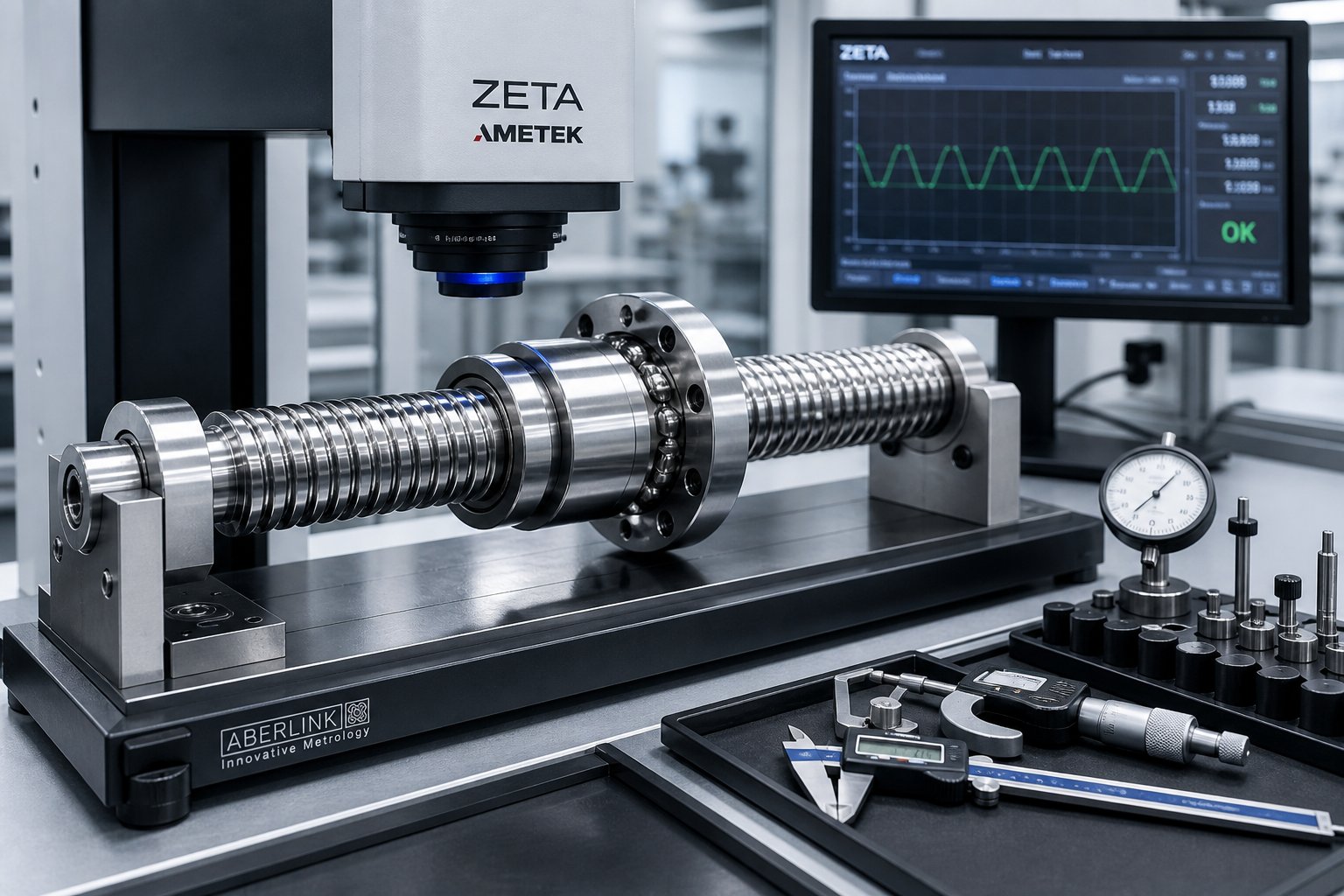
Manufacturing Decision Framework for Evaluating Planetary Roller Screw Manufacturers
Knowing how a planetary roller screw is manufactured is valuable. Knowing how to use that knowledge when specifying components and selecting suppliers is transformative. Engineers and procurement teams who understand the relationship between design requirements and manufacturing processes can write sharper RFQs, ask better questions during supplier audits, and ultimately distinguish between vendors who genuinely control precision — and those who merely claim to.
This section bridges the gap between the process knowledge built throughout this guide and the practical sourcing decisions that knowledge should inform. Think of it as a translation layer: design intent on one side, manufacturing reality on the other, and a clear framework connecting them.
How Design Requirements Drive Manufacturing Choices
Every specification on a planetary roller screw data sheet traces back to a specific manufacturing decision. A high dynamic load rating is not achieved by wishful thinking on a drawing — it is achieved by selecting the right thread profile, grinding it to the right tolerance, hardening the steel to the right depth, and finishing the surface to the right roughness. When you specify a performance parameter, you are implicitly specifying a manufacturing process chain.
The table below maps the most common design requirements to the manufacturing decisions they influence and the typical process selections that result. Use it as a quick-reference tool when preparing specifications or evaluating whether a supplier's proposed process matches your application's demands.
| Design Requirement | Influenced Manufacturing Decision | Typical Process Selection |
|---|---|---|
| High dynamic load rating (C > 100 kN) | Thread profile geometry and thread generation method | Gothic arch profile with precision thread grinding (IT1-IT3); through-hardened AISI 52100 or deep-case-hardened 20MnCr5 |
| High-speed operation (> 2000 RPM input) | Surface finish on raceways and lubricant retention strategy | Superfinished thread flanks (Ra < 0.2 µm); phosphate break-in coating; precision-balanced roller set |
| Precision accuracy class (IT1-IT3) | Thread grinding passes, inspection depth, and preload method | Multi-pass CNC thread grinding with in-process gauging; 100% lead measurement; nut face grinding for preload |
| Corrosive operating environment (marine, chemical, food processing) | Material grade selection and protective surface treatment | Stainless steel grades (AISI 440C or 304L); hard chrome or electroless nickel plating; DLC coating for dry-running conditions |
| High duty cycle / continuous operation (S1) | Heat treatment depth, surface hardness, and lubrication provisions | Deep case-hardening (> 1.5 mm effective case depth); 60+ HRC surface; integrated lubrication ports with automated re-lube capability |
| Low noise / vibration-sensitive application | Cage manufacturing precision, surface finishing depth, and roller matching | Wire-EDM metal cage or precision-molded polymer cage; superfinished all contact surfaces; rollers matched within 1 µm diameter band |
| Compact envelope / high force density | Roller count optimization and thread profile efficiency | Maximized roller count with Gothic arch profile for four-point contact; standard planetary design for highest load-to-size ratio |
| Shock and impact loading | Core toughness and case depth balance | Case-hardened 16MnCr5 or 20MnCr5 with tough core (32-42 HRC) and hard case (60+ HRC); avoid through-hardened brittle cross-sections |
Notice the pattern? No single manufacturing decision exists in isolation. Specifying a high dynamic load rating simultaneously constrains the thread profile (Gothic arch), the thread generation method (grinding), the steel grade (bearing-quality with sufficient hardenability), and the heat treatment strategy (through-hardening or deep carburizing). Changing any one of these creates a ripple effect through the entire process chain. This interconnectedness is precisely why manufacturing expertise matters as much as design engineering when sourcing planetary roller screws — and why procurement teams need a structured way to evaluate whether a supplier truly controls these interdependent processes.
Evaluating Planetary Roller Screw Manufacturers
Imagine walking into a supplier's facility, or reviewing their capability presentation over a video call. You see impressive machines, clean workspaces, and confident technical staff. How do you distinguish between genuine manufacturing control and a polished showroom? The answer lies in asking specific, process-level questions that only a manufacturer with true in-house expertise can answer substantively.
As procurement audit frameworks emphasize, a high-risk supplier is one that outsources grinding or heat treatment and performs assembly only, while a validated tier-one supplier maintains 100% in-house grinding, matching, and assembly — delivering predictable lead times and direct accountability for quality escapes.
Here is a practical checklist of questions procurement teams should present to any prospective planetary roller screw manufacturer:
- In-house thread grinding capability — Does the supplier own and operate CNC thread grinding machines, or is grinding outsourced to a subcontractor? A supplier who outsources this step surrenders control over the single most precision-critical operation in the entire manufacturing chain. Ask to see the machine list, including make, model, and age of each grinder.
- Heat treatment traceability — Can the supplier provide furnace charts, thermocouple records, and quench parameter logs for your specific batch? Heat treatment without documentation is heat treatment without accountability. Every lot should be traceable from raw material certification through hardness verification.
- Inspection equipment inventory — What instruments are on the shop floor for thread profile measurement, surface roughness verification, roundness, and lead accuracy? Ask specifically about optical profilometers, coordinate measuring machines, and Barkhausen noise analyzers for grinding burn detection. The depth of a supplier's metrology investment directly reflects how seriously they take process control.
- Achieved Cpk values on critical dimensions — Statistical process capability indices tell you whether a manufacturing process is merely meeting tolerance or is genuinely centered and stable within it. A supplier who can quote Cpk values of 1.33 or higher on thread pitch, surface roughness, and concentricity demonstrates a level of process discipline that catalog specifications alone cannot convey.
- First-article inspection (FAI) reports — Is the supplier willing to provide a comprehensive dimensional report on the first production unit, verifying every critical feature against the drawing before releasing full production? Resistance to FAI requests is a significant red flag — it often signals that the supplier lacks the measurement capability or process confidence to back up their specifications with data.
- Functional testing protocol — Does the supplier perform dynamic run-in testing, backlash measurement, and torque charting on every assembled unit, or do they ship based on theoretical calculations alone? A supplier that provides 100% functional testing guarantees plug-and-play installation and minimizes commissioning delays at your facility.
- Material sourcing and dual-sourcing strategy — Where does the raw steel come from, and does the supplier maintain alternative sources? A single-source dependency on specialty bearing steel creates supply chain vulnerability that can halt your production line during raw material shortages.
These questions are not designed to trip up suppliers — they are designed to reveal the depth of manufacturing control behind the catalog numbers. A manufacturer who answers each one with specifics, data, and documented evidence is a manufacturer who understands that you are not just buying a piece of steel — you are buying the supplier's quality control ecosystem.
One additional dimension worth evaluating is the breadth of a supplier's thread manufacturing expertise. Planetary roller screws are among the most demanding applications for precision threaded components, but they are not the only ones. Manufacturers whose capabilities extend across related precision screw domains — rather than being limited to a single product family — often demonstrate deeper process maturity and more robust quality systems. For example, manufacturers producing not only standard planetary roller screw assemblies but also planetary screw barrel components for plasticizing and dispersion applications — such as NANHAIYA — apply the same thread-grinding, heat-treatment, and quality-inspection disciplines across both linear motion and polymer extrusion processing. That cross-domain experience signals transferable expertise: the ability to hold tight thread tolerances across different geometries, materials, and operating environments rather than relying on a narrow, single-application process recipe.
This matters for procurement because it reduces risk. A supplier whose manufacturing fundamentals are validated across multiple precision screw product lines is less likely to struggle when your application introduces a non-standard diameter, a custom thread profile, or an unusual material requirement. Their process infrastructure — the grinding machines, heat treatment furnaces, inspection instruments, and the engineering knowledge that ties them together — has been stress-tested against a broader range of challenges.
The price of a planetary roller screw is primarily driven by grinding time, heat treatment complexity, and inspection depth. If a supplier offers a price that is 40% below the market average, it is highly likely they are using inferior materials, skipping critical grinding passes, or avoiding rigorous quality testing. Total cost of ownership over a 5-to-10-year horizon — factoring in unplanned downtime, replacement costs, and maintenance frequency — almost always favors the supplier who invests in manufacturing control over the one who competes on initial price alone.
Armed with this framework — design requirements mapped to manufacturing processes, and a structured approach to evaluating whether suppliers actually control those processes — engineering and procurement teams can move beyond catalog comparisons and into evidence-based sourcing decisions. The final step is connecting everything covered in this guide into a unified perspective on what manufacturing precision truly means for application performance.
From Manufacturing Knowledge to Precision Sourcing
Strip away the technical detail, and a single truth runs through every stage of this guide: a planetary roller screw is only as good as the weakest link in its manufacturing chain. Not the most impressive specification on its data sheet. Not the boldest claim in its catalog. The weakest process step — the one where tolerances slip, surface finish degrades, or heat treatment falls short — defines the ceiling of the finished assembly's real-world performance.
Connecting Manufacturing Precision to Application Performance
Consider how each stage compounds into the final result. Material selection determines whether the steel can achieve uniform hardness without brittle zones — setting the upper boundary on contact fatigue life before a single chip is cut. Rough machining and blank preparation establish the geometric foundation, and any straightness error or stock imbalance introduced here propagates through every downstream operation. Thread grinding on the screw shaft, rollers, and nut bore transforms raw cylinders into the precision-contact surfaces that carry load — and the achievable tolerance class at this stage directly dictates how evenly that load distributes across the roller set.
Heat treatment restructures the steel's microstructure to resist millions of cyclic contacts, but it also introduces distortion that only carefully calculated grinding stock allowances can absorb. Surface finishing refines what grinding started, pushing roughness values below the threshold where hydrodynamic lubricant films form reliably and micropitting initiates. Assembly and preload adjustment bring individually precise components into system-level harmony, eliminating backlash and ensuring that every roller shares the load rather than a few carrying disproportionate burden. And quality inspection — performed not just at the end but continuously through statistical process control — catches the deviations that human senses cannot detect.
None of these stages operates in isolation. A Gothic arch thread profile selected during design locks in the grinding method, which constrains the achievable cycle time, which influences unit cost. A case-hardening steel chosen for its tough core simultaneously demands longer furnace times and deeper carburizing cycles. A superfinished raceway that reduces noise also extends lubricant life, which reduces maintenance intervals, which lowers total cost of ownership over the mechanism's service life.
Every micrometre of manufacturing precision translates directly into newtons of load capacity, hours of service life, and decibels of operating noise — making process mastery the true differentiator between a planetary roller screw that meets specification and one that delivers reliable long-term performance.
This cumulative relationship is why two planetary roller screws with identical catalog ratings can perform dramatically differently in the field. The numbers on the data sheet describe what the design intends. The manufacturing process determines what the hardware actually delivers.
Applying This Knowledge to Your Next Sourcing Decision
You now have something most procurement teams and design engineers lack: a complete mental model of how planetary roller screws are made, from steel billet to final inspection. That model is not academic — it is a practical tool. Here is how to put it to work.
When writing RFQs, go beyond specifying load ratings and accuracy classes. Call out the manufacturing requirements that produce those ratings: thread grinding method, target surface roughness on raceways, heat treatment protocol with traceability documentation, and Cpk thresholds on critical dimensions. Suppliers who can respond to these requirements with specifics — not just compliance checkboxes — are the ones whose manufacturing processes actually support the performance you need.
When evaluating supplier quotes, use manufacturing knowledge to decode pricing. A quote that is dramatically lower than competitors almost certainly reflects shortcuts somewhere in the process chain — inferior steel grades, fewer grinding passes, or outsourced heat treatment without traceability. The manufacturer evaluation checklist from the previous section gives you the questions to identify exactly where those shortcuts are hiding.
When diagnosing field failures, trace backward through the manufacturing chain. Premature pitting on one roller suggests uneven load sharing caused by thread pitch error or cage pocket misalignment. Rapid backlash growth points to inadequate preload or insufficient surface hardness. Excessive noise at commissioning often indicates surface finish rougher than specified or chatter marks from an unstable grinding process. Each failure mode maps to a specific manufacturing stage — and understanding that mapping turns troubleshooting from guesswork into root-cause analysis.
For engineering teams whose applications extend beyond linear motion into plasticizing, mixing, or polymer dispersion, the same precision thread manufacturing principles detailed throughout this guide apply directly to planetary screw barrel components. NANHAIYA's planetary screw barrel product line offers custom components engineered with the thread-grinding accuracy, heat treatment control, and quality inspection rigor that this guide has established as the baseline for reliable performance — providing a direct path from the manufacturing education in these pages to application-ready components for extrusion and compounding systems.
Whether you are specifying a planetary roller screw for a robotic actuator, a servo press, or a satellite positioning system, the core principle remains unchanged: understand the manufacturing, and you understand the product. Catalog numbers describe intentions. Manufacturing processes deliver results. The engineers and procurement professionals who internalize that distinction will consistently source components that perform — not just on paper, but under load, at speed, and across the full service life the application demands.
Frequently Asked Questions About Planetary Roller Screw Manufacturing
1. What steel grades are used to manufacture planetary roller screws?
The most common steel grades include AISI 52100 (100Cr6) for through-hardened screw shafts and rollers, and case-hardening steels such as 16MnCr5 and 20MnCr5 for larger components requiring a hard surface over a tough core. For corrosive environments like food processing or marine applications, stainless variants such as AISI 440C or 304L are used, though they introduce additional machining complexity due to lower machinability and different heat treatment protocols.
2. Why is thread grinding preferred over thread rolling for high-precision planetary roller screws?
Thread grinding achieves accuracy classes up to IT1 and surface finishes as fine as Ra 0.2 micrometres, which are essential for Gothic arch thread profiles that require sub-micrometre form accuracy on each flank. Thread rolling, while faster and capable of work-hardening the surface, cannot consistently replicate the complex curvature of Gothic arch profiles at the small diameters typical of planetary roller screw components. Grinding remains the only viable method when four-point contact geometry and single-digit micrometre tolerances are required.
3. What is the correct manufacturing sequence for planetary roller screw components and why?
The mandatory sequence is rough machining, then heat treatment, then finish grinding. Rough machining is performed while steel is still soft (20-30 HRC) to remove bulk material economically. Heat treatment then hardens the components to 58-62 HRC but introduces minor dimensional distortion. Finish grinding corrects that distortion using the machining allowances left during rough turning. Reversing this order would either destroy achieved tolerances or make material removal prohibitively expensive on hardened steel.
4. How do you evaluate the quality of a planetary roller screw manufacturer?
Key evaluation criteria include verifying in-house thread grinding capability rather than outsourced operations, requesting heat treatment traceability with furnace charts and quench logs, reviewing the inspection equipment inventory for optical profilometers and CMMs, asking for achieved Cpk values of 1.33 or higher on critical dimensions, and confirming willingness to provide first-article inspection reports. Manufacturers whose expertise spans related precision screw domains — such as NANHAIYA, which produces both linear motion components and planetary screw barrels for plasticizing applications — often demonstrate deeper process maturity across thread grinding, heat treatment, and quality control.
5. What are the most common manufacturing defects in planetary roller screws and how are they prevented?
The most consequential defects include grinding burns from excessive heat generation (prevented by controlled feed rates and coolant flow), thread pitch errors caught through lead measurement on optical comparators, heat treatment distortion exceeding grinding stock (prevented by controlled quench parameters and historical distortion data), cage pocket misalignment from fixture drift (prevented by periodic calibration), and grinding chatter marks caused by wheel imbalance or machine vibration. Robust statistical process control tracking Cpk values on critical dimensions catches process drift before it produces out-of-specification parts.
Written by
Nanhaiya Technical Team
Zhoushan Nanhaiya Plastic Machinery Co., Ltd.
The Nanhaiya technical team supports screw and barrel manufacturing projects through application review, technical communication, custom manufacturing coordination, and production and quality control.
Discuss Your Application
Related Articles
More insights on screw barrel technology and plastics processing.
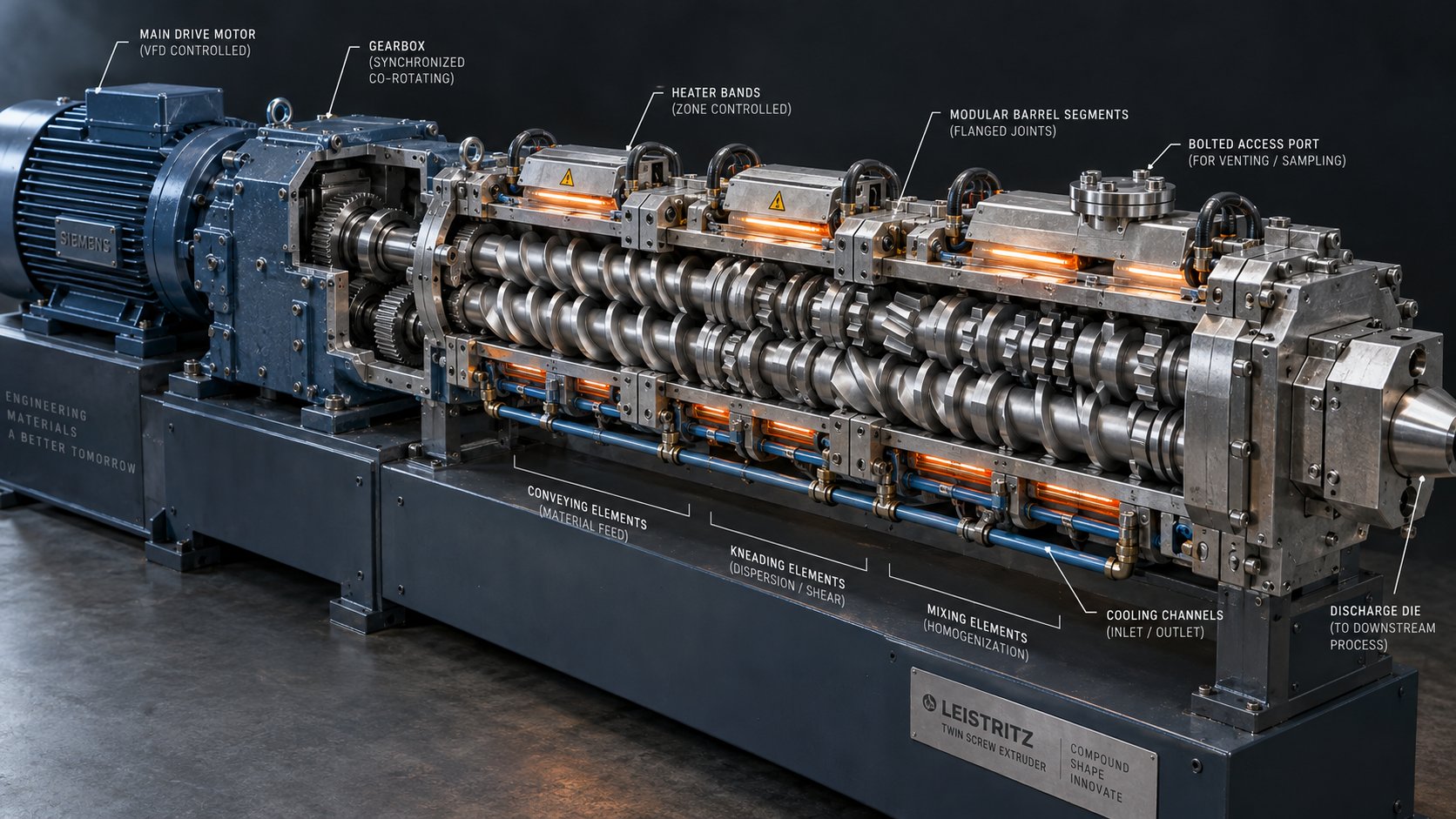
Co Rotating Twin Screw Extruder Parts: From Drive To Die Face
Oct 12, 2026
Complete guide to co rotating twin screw extruder parts — screw elements, kneading blocks, barrel segments, drive components, and material grades explained for sourcing and optimization.
Read Article
What Nobody Tells You About Screw Barrel For Plastic Machine Design
Oct 10, 2026
Learn how screw barrel for plastic machine design affects melt quality, throughput, and wear life. Covers geometry, resin matching, troubleshooting, and sourcing.
Read Article
Single Screw Extruder for Sheet: Stop Guessing, Start Specifying
Oct 9, 2026
Learn how to specify a single screw extruder for sheet production. Covers screw geometry, resin-specific processing, troubleshooting, and maintenance best practices.
Read ArticleLooking for something else?
Search by material, symptom or product and jump straight to the relevant page.
These are navigation suggestions based on keyword matching — not a quotation, not a delivery commitment, and not a substitute for engineering review. Final specification is confirmed by our engineers against your drawings and processed material.
Need help with screw barrel selection?
Share your machine model, processed material and application. Our team can help with pricing and technical support.