

What Planetary Roller Screws Are and Why Manufacturing Precision Matters
What is a planetary roller screw, and why does the way it is built matter as much as the way it is designed? At its core, a planetary roller screw is a mechanical drive that converts rotary motion into linear motion using a central screw shaft, multiple threaded planetary rollers, and an internally threaded nut. Unlike a ball screw, which relies on recirculating ball bearings, the planetary roller screw mechanism distributes load across numerous thread-to-thread contact lines simultaneously. The result is dramatically higher load capacity, greater rigidity, and longer service life within a remarkably compact envelope.
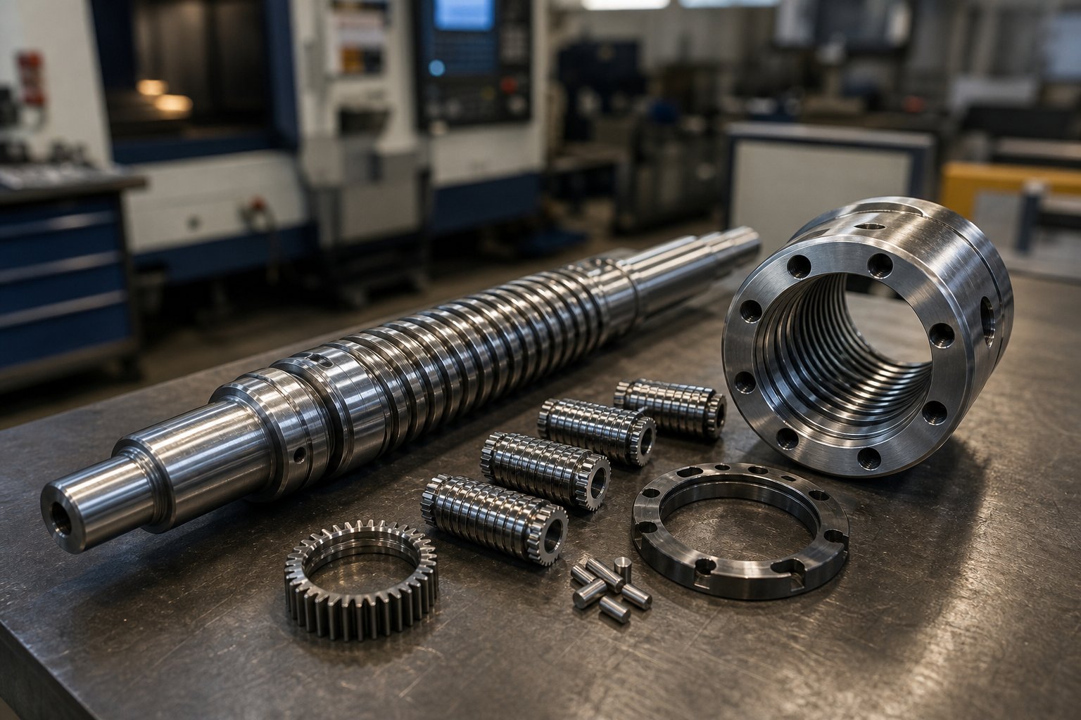
A planetary roller screw consists of a precision screw shaft surrounded by several small threaded rollers held in a planetary arrangement within an internally threaded nut. The rollers engage both the screw thread and the nut's internal thread, converting rotational input into linear output through distributed multi-point contact.
How the Planetary Roller Screw Mechanism Works
Imagine a miniature solar system inside a steel cylinder. The central screw shaft acts as the sun, and the threaded rollers orbit around it like planets -- spinning on their own axes while simultaneously revolving around the shaft. Geared rings at each end of the nut mesh with toothed ends on the rollers, synchronizing their orbital and rotational speeds so every roller maintains precise thread engagement with both the screw and the nut's internal thread.
This planetary motion is what gives the mechanism its name -- and its performance advantage. Because the load is shared across multiple rollers and many contact lines rather than discrete ball contacts, planetary roller screws achieve significantly higher dynamic load ratings than comparably sized alternatives. The fine thread pitch also delivers a high mechanical advantage, meaning less input torque is needed to generate a given linear force.
Why Manufacturing Precision Defines Performance
Here is the challenge that makes this manufacturing process guide for planetary roller screws essential reading: every single roller in the assembly must share the load equally. If one roller sits even a few micrometers off its ideal position or carries a thread profile that deviates slightly from its neighbors, load distribution becomes uneven. Research into load distribution in planetary roller screw assemblies confirms that the first engaged thread already carries a disproportionately high load -- and manufacturing inconsistencies amplify that imbalance, accelerating wear and risking premature failure.
This is why high precision planetary roller screws demand shape and position tolerances in the single-digit micrometer range with surface finishes as fine as Ra 0.4. Tolerances at each manufacturing stage -- material selection, turning, heat treatment, thread grinding, and assembly -- cascade through the final product. A slight dimensional drift during thread production compounds after hardening, which compounds again during final grinding. The manufacturing process, not just the design on paper, ultimately determines load capacity, mechanical efficiency, and service life.
This guide takes a different approach from generic process-flow overviews. Rather than walking through a single linear sequence, it breaks down manufacturing requirements component by component -- screw shaft, planetary rollers, nut, ring gear, and carrier -- detailing the specific challenges, tolerances, and trade-offs that engineers and procurement professionals need to evaluate when specifying or sourcing these critical assemblies. The journey starts where every manufacturing decision begins: the raw material sitting on the shop floor.
Raw Material Selection and Steel Alloy Specifications
That bar of steel sitting on the receiving dock? It has already narrowed -- or expanded -- every manufacturing option that follows. In planetary roller screws manufacturing, raw material selection is not a procurement formality. It is the first engineering decision, and it quietly governs heat treatment strategy, grinding parameters, achievable surface hardness, and ultimately the tolerances your finished assembly can hold. Choose the wrong alloy, and no amount of downstream precision can fully compensate.
So what materials are actually used for high precision planetary roller screws, and why does the choice vary from one component to the next?
Steel Alloy Compositions for Screw Shafts, Rollers, and Nuts
Three families of steel dominate the landscape, each tailored to a specific combination of hardness, toughness, and manufacturability.
Bearing steels -- most notably AISI 52100 (known as 100Cr6 under DIN or SUJ2 under JIS) -- are the workhorse materials for screw shafts and planetary rollers. These are high-carbon, chromium-containing low alloy steels specifically engineered for anti-friction applications. AISI 52100 contains 0.93-1.05% carbon and 1.35-1.60% chromium, giving it exceptional wear resistance and rolling contact fatigue strength. Through-hardened in oil from approximately 816°C, it readily achieves HRC 60-64, placing it squarely in the hardness range required for precision thread raceways. Its high carbon content means the entire cross-section hardens uniformly -- no case depth to worry about, no soft core surprises.
Case-hardening steels like 16MnCr5 (1.7131) and 20MnCr5 (1.7147) take a fundamentally different approach. These low-carbon alloys are tough and ductile in their core but develop an extremely hard outer case through carburizing -- a diffusion process that enriches the surface layer with carbon before quenching. Typical case depths range from 0.4 mm to 1.5 mm depending on component size, with surface hardness reaching HRC 58-62 while the core remains at HRC 30-40. This combination makes case-hardening steels ideal for nuts and ring gears that must resist surface wear while absorbing shock loads without brittle fracture.
Through-hardening tool steels -- such as AISI D2 or equivalent grades -- occasionally appear in specialized or heavy duty planetary roller screws where extreme wear resistance justifies higher material cost. These chromium-molybdenum-vanadium alloys can reach HRC 58-62 and offer superior dimensional stability during heat treatment, but they are significantly harder to machine in the annealed state and demand more aggressive grinding parameters after hardening.
| Alloy Type | Typical Grades | Hardening Method | Achievable Hardness Range | Best Suited Component |
|---|---|---|---|---|
| Bearing Steel (Through-Hardening) | 52100 / 100Cr6 / SUJ2 | Oil or water quench + temper | HRC 60-64 | Screw shafts, planetary rollers |
| Case-Hardening Steel | 16MnCr5, 20MnCr5 | Carburizing + quench + temper | HRC 58-62 (case) / HRC 30-40 (core) | Nuts, ring gears, carriers |
| Through-Hardening Tool Steel | D2 / 1.2379, DC53 | Vacuum hardening + temper | HRC 58-62 | Specialty shafts, high-wear components |
You'll notice the pattern: components with rolling or sliding contact on thread flanks -- shafts and rollers -- gravitate toward bearing steels for their fatigue performance. Components absorbing structural loads or housing other parts lean toward case-hardening steels for their toughness. Planetary roller screw manufacturers who build both standard and heavy duty planetary roller screws often maintain inventory of at least two alloy families to cover this range.
How Material Choice Cascades Through Every Manufacturing Decision
Here is where material selection becomes genuinely consequential. The alloy you pick does not just determine hardness -- it sets off a chain reaction across every downstream process.
Consider the decision sequence:
- Alloy composition dictates the heat treatment method. A 52100 shaft undergoes through-hardening (oil quench from ~816°C, temper to target). A 20MnCr5 nut requires carburizing at 900-930°C for hours, followed by quenching and tempering. These are entirely different furnace cycles, atmospheres, and time commitments.
- Heat treatment method determines case depth and distortion behavior. Through-hardened parts distort relatively uniformly. Carburized parts develop residual stresses at the case-core boundary that cause unpredictable dimensional changes -- sometimes 10-20 micrometers on critical diameters.
- Distortion behavior determines grinding stock allowance. More distortion means more material must be left on the part before heat treatment, which means heavier grinding passes afterward. For a screw shaft where thread form accuracy matters at the micrometer level, excessive grinding stock can introduce thermal damage or residual stress from aggressive material removal.
- Grinding stock allowance determines final achievable tolerances. Tighter tolerances demand lighter, more controlled finishing passes -- which only work if the grinding stock is already minimal and predictable.
In short, a seemingly simple procurement decision -- choosing 52100 over 20MnCr5, or vice versa -- reverberates through heat treatment planning, grinding cycle design, and final dimensional capability. Engineers evaluating planetary roller screw manufacturers should ask not just what alloy is used, but why that alloy was selected for each specific component.
Aerospace and defense applications add another layer. Material certification and traceability become non-negotiable. Each bar of incoming stock typically requires mill certificates conforming to standards such as ASTM A295 for bearing steels, documenting the full chemical composition (carbon, chromium, manganese, phosphorus, sulfur, silicon content), heat number, and mechanical properties. Many specifications mandate that the steel be vacuum arc remelted (VAR) to minimize inclusion content -- microscopic oxide or sulfide particles that act as fatigue crack initiation sites under rolling contact loads.
Incoming material inspection at a capable facility goes well beyond checking paperwork. Spectrographic analysis verifies that the chemical composition actually matches the certificate. Hardness testing -- typically Brinell or Rockwell -- confirms the material is in the expected annealed condition for machining. Some manufacturers also perform ultrasonic inspection of bar stock to detect subsurface defects before any machining time is invested.
Batch variation matters more than many engineers realize. Even within specification limits, a heat of 52100 at 0.93% carbon behaves differently during hardening than one at 1.05% carbon. That variation translates into slightly different as-quenched hardness, slightly different distortion, and slightly different grinding response. High-volume planetary roller screws manufacturing operations mitigate this by qualifying each incoming batch and adjusting furnace recipes accordingly -- a discipline that separates consistent producers from those with erratic quality.
Material selection, then, is not a checkbox. It is the foundation that either enables or constrains every process that follows -- from the first rough-turning cut to the final thread grinding pass that brings each component into tolerance.
Component-by-Component Manufacturing Breakdown
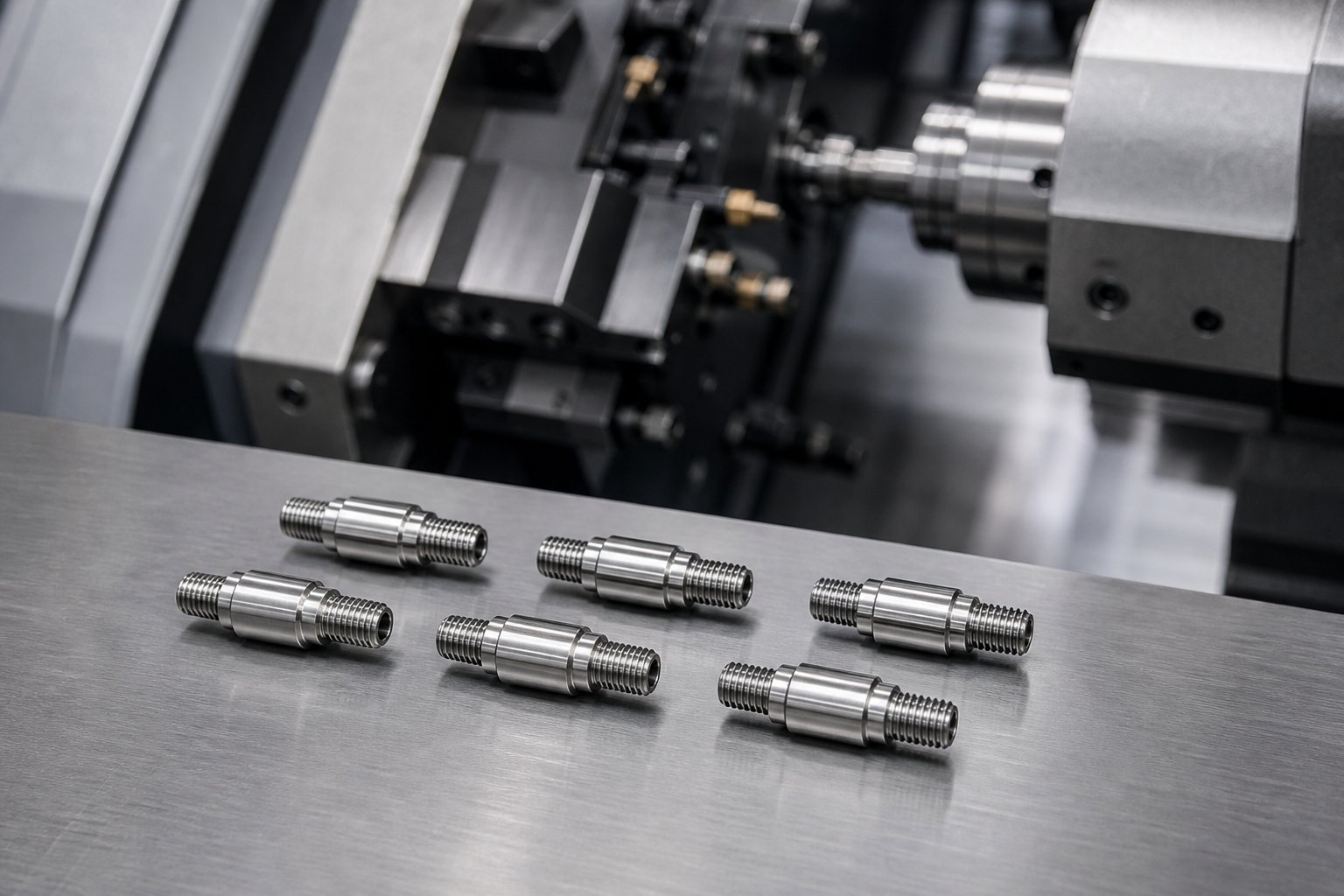
A generic process flow -- rough, heat treat, grind, assemble -- tells you what happens but not where precision is won or lost. Each planetary roller screw component presents its own geometry, fixturing constraints, and failure modes. Understanding these individually is what separates a specification that looks good on paper from one that performs under load.
Screw Shaft Turning, Threading, and Profile Finishing
The screw shaft is the geometric backbone of the entire assembly. Every roller orbits it, every load path passes through it, and every thread flank on the nut references it. Fabrication follows a multi-operation sequence, each stage building on the precision of the last.
It starts with rough turning from bar stock on a CNC lathe. At this point, the steel -- still in its soft, annealed state around 20-30 HRC -- is shaped into a stepped cylindrical profile: bearing journal diameters, thread zones, and shoulder features. Machinists deliberately leave several tenths of a millimeter of stock on every critical surface. That extra material exists for one reason: to absorb the dimensional distortion that heat treatment will introduce later.
After rough turning, a stress-relief cycle relaxes internal stresses introduced by the cutting forces. Skip this step, and those stresses release unpredictably during hardening -- warping the shaft beyond what grinding stock can correct. Semi-finish turning then refines the profile closer to final dimensions while maintaining the allowances needed downstream.
Thread production is the defining operation. Whether the shaft receives its thread profile through grinding, whirling, milling, or rolling depends on the target precision class -- a topic the next chapter covers in detail. What matters here is the critical geometric relationship: concentricity between the thread form and the bearing journals must be held to single-digit micrometer levels. If the thread axis drifts even slightly relative to the journals, every roller in the assembly encounters a cyclic runout error with each revolution. That error manifests as vibration, uneven wear, and reduced service life.
Final grinding after heat treatment corrects any distortion and brings diameters, surfaces, and thread profiles into their finished tolerances. For shafts with length-to-diameter ratios exceeding 7:1 -- common in actuator-length designs -- steady rests and center-drive workholding become essential to prevent deflection under grinding forces.
Planetary Roller Manufacturing -- The Defining Component
If any single part reveals a manufacturer's true capability, it is the planetary roller. Most manufacturing guides gloss over these tiny threaded cylinders entirely. That silence is telling -- because roller production is arguably the most technically demanding step in the entire process chain.
Imagine threading a cylinder barely wider than a pencil lead. Planetary rollers typically measure just 3 to 8 millimeters in diameter, yet each one must carry a thread profile that matches the screw shaft with sub-micrometer geometric fidelity. Every flank angle, every pitch interval, every root radius on the roller must correspond precisely to its counterpart on the shaft. At this scale, conventional fixturing methods simply do not work -- a standard lathe chuck would either crush the part or allow enough deflection to destroy accuracy.
Blank preparation relies on CNC Swiss-type lathes, where a guide bushing supports the workpiece immediately adjacent to the cutting point. This close support minimizes unsupported length, dramatically reducing deflection and chatter. Swiss-type turning establishes the roller's outer diameter and end geometry, holding tolerances as tight as plus or minus 0.02 mm -- the foundation that thread production builds upon.
After heat treatment, thread profiles are ground onto each roller using dedicated small-diameter thread grinding machines with narrow CBN or diamond wheels. Heat management is critical: on a part this small, even minor thermal expansion during grinding pushes the thread form outside tolerance. Controlled coolant flow and conservative feed rates are not refinements -- they are necessities.
For lower precision classes (IT7-IT9), thread rolling offers a faster alternative. Hardened dies press the thread form into the roller blank through plastic deformation, work-hardening the surface and improving fatigue resistance without additional heat treatment. However, for high precision planetary roller screws with Gothic arch profiles, grinding remains the only viable method because rolling cannot consistently replicate the complex flank curvature at roller-scale diameters.
Here is the insight that matters most for assembly performance: roller-to-roller dimensional consistency directly determines load sharing. If you study any planetary roller screw diagram, you will notice that all rollers engage the shaft and nut simultaneously. A roller that is even 2-3 micrometers oversize relative to its neighbors carries a disproportionate share of the load. Over millions of cycles, that overloaded roller wears faster, its thread form degrades, and the imbalance cascades through the entire assembly. Manufacturers targeting zero-defect production typically sort rollers into matched sets -- grouping them by measured pitch diameter within a 1-2 micrometer band -- to ensure uniform load distribution in the finished roller planetary screw.
Nut, Ring Gear, and Carrier Production
The planetary roller screw and nut function as a matched system, and the nut's internal thread must mesh with every roller simultaneously. A dimensional error on the screw shaft affects one contact line at a time. A deviation in the nut thread affects every roller at once -- making it the highest-consequence feature in the assembly.
EMAG identifies the nut as the most challenging component to manufacture, and the reasons are geometric. A typical nut for robotic applications measures roughly 150 mm long with an inner diameter of approximately 20 mm -- a length-to-diameter ratio of 7:1 or more. After heat treatment, the bore must be threaded in steel hardened to 60 HRC or higher, with surface roughness held to Ra 0.4, roundness to 0.025 mm, and concentricity to 0.025 mm.
Internal thread machining follows a two-stage sequence. First, precision boring and semi-finish turning establish the near-net thread form while chip evacuation is still manageable. Then, internal thread grinding with small-diameter CBN wheels delivers the final dimensions and surface quality, achieving pitch errors below 2 micrometers between individual thread turns. The confined bore geometry creates three simultaneous challenges: limited grinding wheel diameter (and therefore reduced stiffness), poor swarf evacuation in deep bores, and concentrated heat buildup with restricted coolant access.
Vertical machine designs offer a significant advantage here -- gravity pulls chips downward and out of the bore rather than allowing them to accumulate and risk surface damage.
The ring gear and carrier, while less discussed, are just as essential for proper roller synchronization:
- Ring gear (toothed end rings) -- Mesh with toothed features on each roller's ends, synchronizing orbital and rotational speeds. Manufacturing involves hobbing for production quantities or wire EDM for prototype runs and complex tooth profiles. Primary challenge: maintaining tooth spacing uniformity so that no individual roller is driven faster or slower than its neighbors, which would disrupt load sharing. Critical tolerance: tooth pitch error held to single-digit micrometer levels.
- Carrier/retainer cage -- Maintains equal angular spacing between all rollers and prevents roller-to-roller contact. Metal cages are precision-stamped or wire-EDM cut from lightweight steel alloys; polymer cages (PEEK, glass-filled nylon) are injection molded for lower-load or high-speed applications. Primary challenge: pocket spacing uniformity -- unequal pocket angles create uneven roller distribution and a vibration signature no amount of shaft or roller precision can eliminate. Critical tolerance: angular pocket spacing within fractions of a degree; axial clearance controlled to prevent roller binding or excessive float.
- Nut housing features -- Beyond the internal thread, the nut requires precision-ground external mounting surfaces, seal grooves, and lubrication ports. Primary challenge: maintaining concentricity between the internal thread datum and external mounting features after heat treatment distortion. Critical tolerance: total indicated runout between bore thread and OD mounting surfaces held below 0.010 mm.
Ring gears and carriers are frequently treated as commodity components, but their manufacturing quality directly governs roller synchronization and spacing. A carrier with inconsistent pocket spacing introduces a vibration pattern that degrades both positioning accuracy and acoustic performance -- particularly consequential in noise-sensitive applications like humanoid robotics or medical positioning systems.
With each component's geometry established, the critical question becomes how thread profiles are actually generated -- and why the method chosen for each part determines the tolerance class, surface quality, and unit cost of the finished assembly.
Thread Production Methods and Tolerance Trade-Offs
The thread profile is where force meets geometry. Every newton of load transmitted through a planetary roller screw passes across thread flanks -- and the method used to create those flanks determines whether contact is smooth and evenly distributed or concentrated at stress-raising irregularities. Three dominant thread production methods compete for this critical role: precision thread grinding, thread whirling, and thread rolling. Each brings a distinct combination of achievable accuracy, surface quality, cycle time, and cost. Choosing correctly for a given planetary roller screw design is not a matter of preference -- it is an engineering decision with quantifiable consequences.
Precision Thread Grinding for High-Accuracy Applications
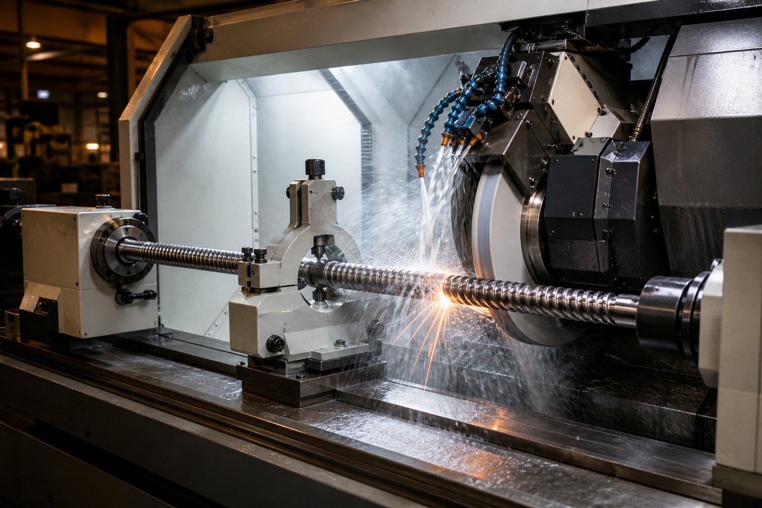
When tolerances tighten to the single-digit micrometer range, thread grinding stands alone. This is the process of generating thread profiles on fully hardened components -- typically HRC 58-62 or higher -- using formed or multi-rib CBN (cubic boron nitride) or aluminum oxide grinding wheels. The wheel carries the inverse of the desired thread form and traverses the rotating workpiece at a precisely controlled lead rate, removing material in successive passes until the final geometry emerges.
What makes grinding irreplaceable for high precision planetary roller screws? Three things converge:
- Lead accuracy in the low-micrometer range. Precision thread grinding machines equipped with linear encoders and in-process gauging routinely hold lead errors below 2-3 micrometers per pitch. For internal threads in hardened nuts, EMAG reports pitch errors of less than 2 micrometers between individual thread turns during finish grinding operations -- a level of consistency that no other process can match on hardened steel.
- Surface finish quality. Ground thread flanks typically achieve Ra 0.2 to 0.4 micrometers, providing the smooth contact surfaces essential for efficient load transmission and long fatigue life. At these finish levels, micro-asperities are small enough that elastohydrodynamic lubrication films can fully separate mating surfaces under operating loads.
- Post-hardening correction capability. Because grinding operates on fully hardened material, it compensates for whatever dimensional distortion heat treatment introduced. This is critical: a screw shaft or nut that warped by 10-15 micrometers during quenching can still be brought back into specification through controlled grinding passes.
The limitations are equally straightforward. Thread grinding is slow -- a single screw shaft may require several minutes per thread, and internal nut threads demand even longer cycle times due to restricted wheel diameters and limited material removal rates inside deep bores. Tooling cost is high. CBN grinding wheels for thread forms are expensive precision tools that require regular profiling (dressing) to maintain form accuracy. For aerospace actuators and robotic joints, these costs are justified by the performance requirements. For high-volume metric planetary roller screw production, grinding is typically reserved for final finishing after a faster roughing method has removed the bulk of material.
Thread Whirling and Thread Rolling Compared
Not every thread operation demands grinding's precision -- or its price tag. Two alternative methods handle roughing, semi-finishing, and in some cases complete thread production at dramatically different speeds.
Thread whirling is a pre-hardening (soft-state) machining process where a ring-shaped cutter head carrying multiple carbide inserts orbits eccentrically around the workpiece while the workpiece itself rotates slowly. The inserts engage the material in an interrupted cutting action, generating the thread profile through successive passes of the orbiting tool. Because whirling removes material in small, chip-breaking arcs rather than continuous cuts, it handles deep thread forms and high helix angles better than single-point turning -- especially on screw shafts with challenging length-to-diameter ratios.
Whirling excels as a semi-finishing operation. It rapidly generates a near-net thread form that leaves just 0.05 to 0.15 mm of stock for final grinding after heat treatment. This two-stage approach -- whirl soft, grind hard -- balances speed and accuracy more cost-effectively than grinding from solid.
Thread rolling takes an entirely different approach. Rather than removing material, rolling displaces it. Two or three hardened cylindrical dies press into the rotating workpiece blank, plastically deforming the surface into the thread form. The blank diameter starts near the pitch diameter, and material flows radially outward to form the thread crests. It is, as Power Transmission Engineering describes, essentially a "continuous but intermittent rotary forging process."
The advantages are compelling. Rolling is typically 5 to 10 times faster than any cutting operation. Surface finishes in the range of Ra 0.02 to 0.10 micrometers -- superior to grinding -- are achieved directly from the forming action, thanks to a burnishing effect at the die-workpiece interface. Grain flow lines remain unbroken, following the rolled form geometry, which combined with compressive residual stresses in the thread roots can make rolled threads 10 to 20 percent stronger in fatigue than equivalent cut threads. Work-hardening during cold rolling adds another 5 to 8 HRC points to the surface, further enhancing wear resistance.
Precision CNC rolling equipment holds part-to-part diameter variation within 0.005 to 0.008 mm and, for infeed rolling, lead variation within 0.002 mm per 25 mm of rolled length. For throughfeed rolling of longer forms, cumulative lead accuracy typically ranges from 0.025 to 0.050 mm per 300 mm under optimized conditions, with standard production achieving 0.100 to 0.150 mm per 300 mm.
The constraints? Rolling works best on materials up to about 36 HRC -- above that, die life drops sharply and forming loads spike. It cannot produce complex Gothic arch profiles at the micro-scale diameters of planetary rollers with consistent fidelity. And tooling investment for custom thread forms is substantial, making rolling most economical at high volumes where die cost is amortized across thousands of parts.
When engineers evaluate planetary roller screw vs ball screw manufacturing, thread production is often where the complexity gap becomes most visible. Ball screw grooves are comparatively simple helical arcs ground into a shaft. Planetary roller screws demand matching thread forms across the shaft, multiple rollers, and the nut -- each requiring method-appropriate thread production with tightly correlated tolerances.
| Method | Process State (Hard/Soft) | Achievable Tolerance Class | Surface Finish Range (Ra) | Cycle Time (Relative) | Best Application |
|---|---|---|---|---|---|
| Thread Grinding | Hard (post heat treatment) | Highest (lead error < 2-3 μm/pitch) | 0.2 - 0.4 μm | Slow (1x baseline) | Final finishing of shafts, rollers, and nut internal threads for aerospace and robotics |
| Thread Whirling | Soft (pre heat treatment) | Medium (semi-finish; 0.05-0.15 mm stock remaining) | 0.8 - 1.6 μm | Moderate (3-5x faster than grinding) | Roughing/semi-finishing screw shafts before hardening and final grind |
| Thread Rolling | Soft (pre or post heat treatment up to ~36 HRC) | Medium-High (lead variation 0.002 mm/25 mm infeed; 0.025-0.050 mm/300 mm throughfeed) | 0.02 - 0.10 μm | Fast (5-10x faster than cutting) | High-volume screw shaft production; standard precision classes |
Matching Thread Method to Planetary Roller Screw Type
The comparison above applies cleanly to standard planetary roller screw configurations, where the screw shaft carries the external thread, the nut carries the internal thread, and the rollers sit between them. But not every planetary roller screw design follows this arrangement -- and the variants demand fundamentally different manufacturing setups.
In a standard configuration, the screw shaft's external thread is the most accessible feature in the assembly. Thread whirling, rolling, and grinding all apply directly, and manufacturers can choose their method based on volume and precision class requirements. The nut's internal thread is more constrained -- whirling and rolling are generally impractical inside a bore, so production follows a turning-then-grinding sequence as described for nut manufacturing.
The inverted planetary roller screw flips the geometry. In inverted planetary roller screws, the nut rotates while the screw body translates linearly -- and critically, the screw body itself may carry an internal thread rather than an external one. This inverted planetary roller screw mechanism demands that thread production tooling reach inside the screw body, which imposes the same deep-bore access challenges normally associated with nut machining: restricted grinding wheel diameters, limited coolant delivery, and difficult chip or swarf evacuation. Manufacturers targeting inverted configurations often require dedicated internal thread grinding machines with extended quill designs and high-pressure through-spindle coolant -- a capital equipment commitment that limits which facilities can produce these variants at all.
The differential planetary roller screw introduces yet another wrinkle. In differential designs, the rollers carry threads with a slightly different pitch than the screw shaft, and the net linear motion per revolution is determined by the pitch difference rather than the absolute pitch. This means thread production must hold not just tight absolute tolerances on each component, but exceptionally tight relative pitch accuracy between the shaft and roller thread families. A lead error that would be negligible in a standard configuration can produce significant positioning error in a differential design because the output motion depends on the small arithmetic difference between two similar pitch values.
For metric planetary roller screw production across all three variants, the practical takeaway is clear: the thread production method cannot be selected in isolation. It must be matched to the specific variant geometry, the target precision class, and the production volume -- with full awareness that a planetary roller screw vs ball screw evaluation often hinges on whether a manufacturer can execute the right threading strategy for the application at hand.
Thread accuracy, however, is only as stable as the machines and tools that produce it. Even the most capable grinding process drifts when cutting tools wear, workholding deflects, or thermal expansion shifts reference surfaces -- realities that demand a disciplined approach to CNC parameters and tooling management.
CNC Machining Parameters and Tooling Strategies for Planetary Roller Screws
A perfect thread grinding program means nothing if the screw shaft flexes under cutting forces, the insert edge crumbles mid-pass, or thermal growth shifts the workpiece datum by fifteen micrometers between morning and afternoon. The planetary roller screw manufacturing process lives and dies in these operational details -- the cutting speeds, feed rates, workholding decisions, and tool life strategies that collectively determine whether a component lands inside tolerance or drifts toward scrap. Surprisingly, this is the territory that most manufacturing process guides for planetary roller screws leave almost entirely blank.
CNC Turning and Milling Parameters for Screw Components
Machining bearing-grade steels like 52100 in their annealed state (approximately 20-30 HRC) is manageable -- but only if you respect the material's tendency to work-harden and generate significant cutting heat. For rough turning of screw shaft blanks, cutting speeds typically fall in the range of 150 to 220 m/min using coated carbide inserts, with depths of cut between 1.5 and 3.0 mm per pass. Feed rates depend on the operation: roughing passes run at 0.2 to 0.35 mm/rev, while semi-finish passes drop to 0.08 to 0.15 mm/rev to reduce surface stress and improve geometric accuracy before heat treatment.
Hard turning -- machining after through-hardening to HRC 58-62 -- changes the equation entirely. Cutting speeds increase to 120 to 180 m/min with CBN (cubic boron nitride) inserts, but depths of cut shrink to 0.10 to 0.30 mm and feeds tighten to 0.05 to 0.12 mm/rev. CBN's exceptional thermal stability and hardness, as outlined in Eagle Superabrasives' guide to CBN, allow it to maintain sharp cutting edges at the elevated temperatures generated by hardened steel contact -- temperatures that would rapidly degrade conventional carbide tooling.
Rigid workholding is arguably the single most important factor in screw shaft machining. Planetary roller screw drive shafts commonly reach length-to-diameter ratios of 7:1 to 8:1, and at those proportions, unsupported workpieces behave less like solid cylinders and more like tuning forks. Every cutting force impulse excites a deflection mode that shows up as taper, chatter marks, or runout in the finished part.
The countermeasures are well established but demand discipline:
- Steady rests positioned at the midpoint or at calculated nodal points along the shaft to suppress the dominant vibration mode. Hydraulic or pneumatic steady rests with self-centering rollers are preferred over fixed-jaw types because they accommodate minor diameter variations without inducing new runout errors.
- Center-drive configurations where both ends of the shaft are supported by live centers while a drive unit engages a pre-machined center section -- eliminating the cantilevered overhang that standard chuck-and-tailstock setups create.
- Climb milling over conventional milling for any thread-related features produced by milling operations. In climb milling, the cutter engages the material at maximum chip thickness and exits at minimum, pulling the workpiece into the fixture rather than pushing it away. This reduces deflection forces on slender shafts and produces a better surface finish on thread flanks -- a meaningful advantage when those flanks will eventually mate with planetary rollers under load.
Vibration damping extends beyond workholding hardware. Tuned boring bars with internal damping masses, optimized tool overhang ratios (keeping unsupported tool length below 4x the bar diameter wherever possible), and spindle speed adjustments to avoid resonant frequencies all contribute to the stability envelope. For metric planetary roller screws produced in medium-to-high volumes, some manufacturers invest in vibration monitoring systems that detect chatter onset in real time and automatically adjust spindle speed or feed rate before surface quality degrades.
Tooling Selection and Tool Life Management
The tooling choices for planetary roller screw components split cleanly along the hardness line. Soft-state operations -- rough turning, semi-finish turning, thread whirling -- use coated carbide inserts (TiAlN or AlCrN coatings) selected for their combination of hot hardness, edge toughness, and resistance to built-up edge formation in chromium-bearing steels. Hard-state operations -- finish turning after heat treatment and all thread grinding -- shift to CBN inserts or CBN grinding wheels.
For thread grinding specifically, the wheel specification is a critical engineering decision. Two abrasive families compete:
- Vitrified CBN wheels offer the highest form-holding capability and free-cutting action. Their porous bond structure allows efficient coolant penetration into the grinding zone, reducing thermal damage risk on hardened thread flanks. CBN wheels maintain dimensional accuracy over long production runs, with dressing intervals that can be three to five times longer than conventional alternatives. This consistency is precisely why CBN dominates in precision planetary roller screw drive component grinding.
- Aluminum oxide (Al2O3) wheels cost less per unit but wear significantly faster. They require more frequent dressing to maintain form accuracy, which introduces periodic interruptions and slightly different geometry after each dress cycle. For standard-precision components or prototype quantities where wheel investment is not justified, alumina wheels remain a practical choice -- but tool life monitoring becomes even more critical.
Here is the connection that most guides miss entirely: tool wear is the primary root cause of dimensional drift in thread form accuracy. As a grinding wheel wears between dressing cycles, its effective diameter decreases, its form profile rounds off at the edges, and the contact geometry subtly shifts. On a thread flank, this shows up as a gradual change in flank angle and pitch diameter -- invisible to the operator but measurable at the micrometer level. Over a production run of fifty screw shafts, that drift can push the last parts outside tolerance even though the first parts were perfect.
Managing this drift requires a closed-loop approach: in-process gauging measures critical thread dimensions at defined intervals, and those measurements feed back into CNC program offsets or trigger automated wheel dressing cycles. Without this feedback loop, quality depends on luck rather than process control.
Common Manufacturing Defects, Root Causes, and Corrective Actions
Understanding the link between tooling condition, machine behavior, and defect generation is essential for anyone evaluating a manufacturer's process maturity. The following defects appear repeatedly in planetary roller screw component production -- and each traces back to a specific, correctable root cause:
- Thread form errors (flank angle deviation, pitch diameter shift) — Root cause: Grinding wheel wear between dressing intervals, or CBN insert edge breakdown during hard turning. Corrective action: Implement in-process gauging with automatic offset compensation; tighten dressing intervals based on statistical trend data rather than fixed part counts.
- Runout and concentricity errors between thread and bearing journals — Root cause: Workholding deflection or inconsistent clamping force, especially on slender shafts. Misaligned steady rests or worn chuck jaws allow the shaft to shift between operations. Corrective action: Verify workholding alignment with dial indicators before each setup; replace worn jaw inserts on a scheduled basis; use hydraulic chucks with verified and consistent clamping pressure.
- Surface finish degradation (grinding burns, feed lines, orange peel texture) — Root cause: Improper coolant delivery -- either insufficient volume, wrong nozzle angle, or coolant that has degraded in concentration or cleanliness. Grinding burns indicate that the coolant film broke down and allowed direct abrasive-to-metal contact at temperatures exceeding the steel's tempering point. Corrective action: Optimize coolant nozzle position to target the exact grinding contact zone; monitor coolant concentration and filtration; reduce feed rate or depth of cut if thermal damage persists.
- Lead accuracy drift (cumulative pitch error over shaft length) — Root cause: Thermal expansion of the workpiece, machine bed, or lead screw during extended grinding cycles. A screw shaft that heats up by just 5°C during grinding expands by roughly 6 micrometers per 100 mm of length in steel -- enough to push cumulative lead error outside specification on long shafts. Corrective action: Allow parts to thermally stabilize before final grinding passes; use temperature-compensated CNC controls; implement mid-cycle gauging to detect and correct thermal drift before it accumulates.
Each of these defects is preventable -- but only when the manufacturing process explicitly addresses the root cause rather than relying on end-of-line inspection to catch failures. A manufacturer whose quality system includes in-process measurement, closed-loop tool compensation, and documented corrective action protocols demonstrates the kind of process maturity that separates reliable planetary roller screw production from trial-and-error machining.
Machining and grinding bring components to their dimensional targets, but the metallurgical properties that determine whether those dimensions survive millions of load cycles are established elsewhere -- in the furnace, the quench tank, and the surface treatment line.
Heat Treatment and Surface Engineering Processes
A screw shaft can be turned and ground to micrometer-level perfection -- and still fail catastrophically in service if its metallurgical structure cannot support rolling contact fatigue. The dimensions you measure on a finished component tell you its shape. Heat treatment and surface engineering determine what that shape can endure.
This is the stage where the alloy decisions made during material selection are finally realized. A 52100 bearing steel shaft enters a through-hardening furnace. A 20MnCr5 nut goes into a carburizing atmosphere. Each follows a fundamentally different thermal path, yet both must emerge with surfaces hard enough to resist wear (HRC 58-62 minimum for raceways), cores tough enough to absorb shock loads, and dimensional distortion predictable enough to leave grinding stock -- not scrap.
Case Hardening and Through-Hardening Protocols
Two hardening strategies dominate planetary roller screw production, and understanding the distinction is essential for anyone evaluating manufacturing capability or specifying components.
Through-hardening applies to bearing steels like 52100 / 100Cr6, where the high carbon content (approximately 1% C) allows the entire cross-section to transform into martensite during quenching. The process sequence is relatively straightforward: heat the component to the austenitizing temperature (typically 830-845°C for 52100), soak to ensure uniform temperature throughout the cross-section, quench in oil to achieve martensitic transformation, and temper at 150-180°C to relieve internal stresses while retaining surface hardness in the HRC 60-64 range. Screw shafts and planetary rollers made from bearing steels typically follow this path.
The beauty of through-hardening is its uniformity. Because hardness develops throughout the part rather than just at the surface, grinding operations can remove material without risk of cutting through a hardened case into a soft substrate. The trade-off? Through-hardened parts are uniformly brittle as well as uniformly hard. For components that must absorb impact loads -- like nuts and ring gears that serve as structural housings -- that brittleness becomes a liability.
Case hardening (carburizing) solves this problem by creating a hard outer shell around a tough, ductile core. Case-hardening steels like 16MnCr5 and 20MnCr5 start with low carbon content (0.16-0.20% C), making them easy to machine in the green state. During carburizing, components are heated in a carbon-rich atmosphere -- traditionally endothermic gas at 900-950°C, or increasingly through low-pressure carburizing (LPC) using acetylene at pressures of just a few millibars -- for several hours. Carbon diffuses into the surface layer, enriching it to approximately 0.7-0.85% C at the target case depth.
Critical carburizing parameters include:
- Carburizing temperature: 900-950°C for conventional gas carburizing; up to 1,050°C for LPC processes, which accelerate carbon diffusion and reduce cycle times.
- Carbon potential: Controlled to achieve 0.7-0.85% surface carbon concentration -- enough for high hardness but not so high that retained austenite or carbide networks form.
- Case depth targets: Typically 0.5-1.3 mm for planetary roller screw nuts and ring gears, depending on component size and load rating. Gear Solutions reports specifications ranging from CHD 0.5-0.8 mm for smaller pinion-scale components to CHD 0.75-1.3 mm for larger gear components.
- Quench media selection: Oil quenching remains common, but high-pressure gas quenching (HPGQ) using nitrogen or helium at 2-20 bar pressure offers significantly more uniform cooling. Unlike oil quenching -- which subjects parts to inhomogeneous film boiling, bubble boiling, and convection phases -- gas quenching produces only convective heat transfer, resulting in a far more homogeneous heat-transfer coefficient across the component surface.
- Tempering temperature: 150-200°C post-quench, balancing residual stress relief against hardness retention. Surface hardness targets of HRC 58-62 (or 64-69 HR45N for certain specifications) must be achieved while the core remains at HRC 28-40 for toughness.
Dimensional distortion during heat treatment is the single largest source of grinding stock requirement -- and therefore directly impacts final tolerance achievability and manufacturing cost.
Why does distortion matter so much? Every component enters the furnace at carefully controlled pre-heat-treatment dimensions. It exits with those dimensions changed -- sometimes by 10-40 micrometers on critical diameters. Three types of stress drive this deformation: residual stresses from prior machining, thermal stresses from temperature gradients during heating and cooling, and transformation stresses from the crystal structure shift as austenite converts to martensite. As AST-Paulo explains, the part's surface cools and transforms first, hardening while the core is still hot and untransformed. When the core finally transforms and expands, it pushes outward against the already-rigid surface -- a "balloon effect" that causes measurable deformation.
For planetary roller screw components, this distortion directly determines how much material the grinding process must remove to achieve final dimensions. More distortion means more grinding stock, which means heavier grinding passes, longer cycle times, and greater risk of thermal damage to the finished surface. Manufacturers who invest in advanced quenching technologies -- like HPGQ with reversing gas flow or dynamic quenching profiles -- can reduce distortion spread by 48-61% compared to conventional oil quenching, as documented in distortion studies on transmission components. That reduction translates directly into tighter achievable tolerances, lower grinding costs, and improved planetary roller screw efficiency through more consistent thread geometry.
Fixture design during heat treatment is another often-overlooked variable. Carbon-reinforced carbon (CFC) fixtures maintain dimensional stability across hundreds of thermal cycles without the deflection or warping that traditional alloy fixtures experience. Proper fixturing ensures horizontal component loading and uniform gas flow around each part during quenching -- factors that can reduce flatness distortion by up to 49% and roundness distortion by 24% compared to standard fixturing approaches.
Surface Treatments and Coatings for Extended Service Life
Heat treatment gives components their mechanical backbone. Surface treatments add the functional skin -- controlling friction, managing corrosion, and optimizing lubricant retention for the specific operating environment each planetary roller screw actuator or linear drive will face.
Three surface treatment families appear most frequently across the industry, each suited to different performance demands:
Black oxide converts the steel surface into a thin magnetite (Fe3O4) layer through a high-temperature alkaline salt bath. The resulting coating is extremely thin -- typically 0.2-1.0 micrometers -- making it ideal for precision components where dimensional impact must be negligible. Black oxide provides mild corrosion protection when sealed with oil or wax and creates a micro-porous surface that retains break-in lubrication during the critical initial operating period. For a planetary roller screw linear actuator in a controlled indoor environment, black oxide on rollers and internal components is often the most cost-effective treatment. Its uniform satin-black finish also reduces light reflection, a minor but practical benefit in optical or clean-room adjacent installations.
Manganese phosphate coating builds a thicker crystalline layer -- 5-20 micrometers, sometimes up to 30 micrometers -- with a porous structure specifically engineered to trap and retain oil. This oil-retaining capability makes manganese phosphate the preferred treatment for heavy-load, slow-speed applications where hydrodynamic lubrication films are too thin to fully separate mating surfaces. The crystalline texture also provides anti-seize properties during initial assembly and break-in. For heavy duty planetary roller screws in servo presses, injection molding machines, or similar high-force applications -- including leads 10-20 planetary roller screw configurations for servo electric cylinder drives -- manganese phosphate coatings extend service intervals by maintaining lubricant at the thread contact zones where it is needed most.
DLC (diamond-like carbon) coatings represent the advanced end of the surface engineering spectrum. Applied through physical or chemical vapor deposition (PVD/CVD), DLC creates an amorphous carbon film with hardness approaching 2,000-5,000 HV -- dramatically harder than the underlying steel substrate. Friction coefficients drop to 0.05-0.15 against steel, compared to 0.15-0.30 for uncoated hardened surfaces. DLC coatings are chemically inert, vacuum-compatible, and outgas-free, making them essential for planetary roller screw actuator assemblies operating in clean rooms, semiconductor equipment, vacuum chambers, or space mechanisms. The cost per component is significantly higher than chemical conversion coatings, but in environments where conventional lubricants cannot be used or where particulate generation must approach zero, DLC is often the only viable option.
| Treatment Type | Process Description | Friction Impact | Corrosion Resistance | Typical Application |
|---|---|---|---|---|
| Black Oxide | Alkaline salt bath converts surface to magnetite (Fe3O4); sealed with oil or wax. Coating thickness: 0.2-1.0 μm. | Slight reduction; oil-sealed surface supports break-in lubrication retention | Mild (requires oil/wax seal); suitable for indoor, controlled environments | Planetary roller screw linear actuator components in robotics, medical devices, indoor automation |
| Manganese Phosphate | Chemical conversion forms porous crystalline Mn phosphate layer. Coating thickness: 5-20 μm (up to 30 μm). | Significant reduction under boundary lubrication; porous structure retains oil at contact zones | Good when sealed; crystalline layer traps protective oil film | Heavy duty servo presses, injection molding, leads 10-20 planetary roller screw for servo electric cylinder applications |
| DLC (Diamond-Like Carbon) | PVD/CVD-deposited amorphous carbon film. Hardness: 2,000-5,000 HV. Coating thickness: 1-4 μm. | Major reduction; friction coefficient 0.05-0.15 vs. steel | Excellent; chemically inert, vacuum-compatible, zero outgassing | Clean-room actuators, semiconductor equipment, vacuum and space mechanisms |
Choosing the right surface treatment is not a standalone decision -- it connects directly back to the alloy and heat treatment already applied. A through-hardened 52100 screw shaft at HRC 62 responds differently to phosphating chemistry than a carburized 20MnCr5 nut at the same surface hardness, because the underlying microstructure and residual stress state influence how the conversion layer nucleates and adheres. Similarly, DLC coatings require substrate surfaces ground to Ra 0.1-0.2 or finer, because the ultra-thin film follows every surface irregularity -- amplifying roughness rather than masking it.
For engineers specifying planetary roller screw efficiency requirements, surface treatment selection directly affects the friction torque budget. A manganese phosphate coating that reduces boundary friction by 15-20% during break-in translates into measurably lower input torque requirements and reduced heat generation at operating speed. A DLC coating that cuts steady-state friction by 40-60% can shift an actuator's thermal equilibrium enough to allow higher duty cycles without external cooling. These are not cosmetic choices -- they are performance engineering decisions embedded in the surface of every component.
With metallurgical properties locked in and surfaces engineered for their target environment, every individual component is now ready to become part of a working mechanism. The challenge shifts from making precise parts to assembling them into an equally precise whole -- a process where roller alignment, preload calibration, and lubrication strategy determine whether the sum truly exceeds its parts.
Assembly Process and Preload Configuration for Planetary Roller Screws
Precision-ground components sitting in trays do not deliver linear force. An assembly does. Yet most manufacturing guides treat the planetary roller screw assembly step as a footnote -- a brief mention of "put the parts together" before jumping to final test results. That silence hides one of the most consequential phases in the entire production chain. A set of individually flawless rollers, shaft, and nut can still produce a defective actuator if they are assembled with incorrect phasing, insufficient preload, or poorly distributed lubrication.
Why? Because assembly is where every upstream tolerance interacts simultaneously for the first time. Thread form accuracy on the shaft meets thread form accuracy on every roller and the nut -- all at once, under contact. Any misalignment, spacing inconsistency, or lubrication gap compounds across every revolution under load.
Roller Alignment and Carrier Loading Procedures
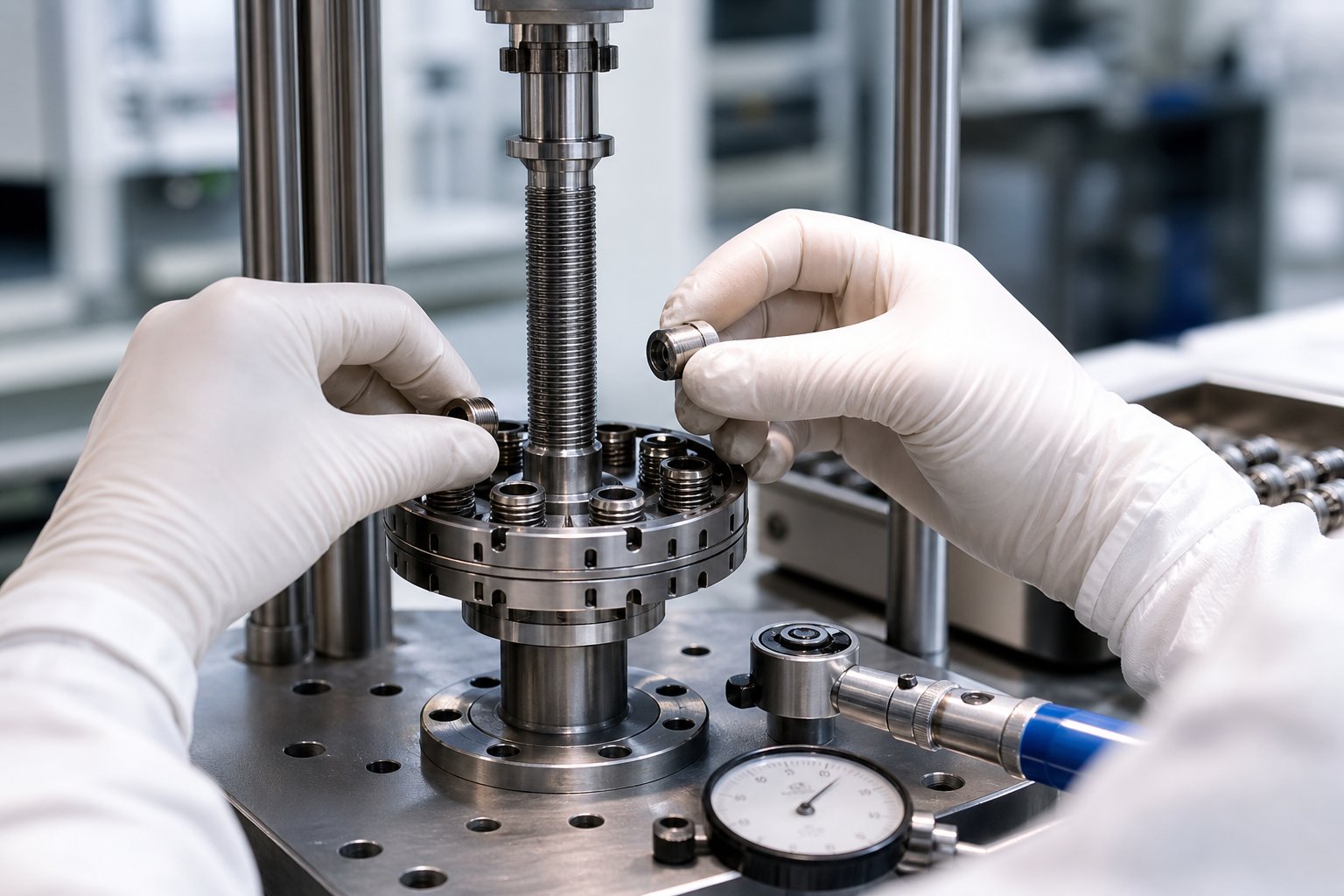
The assembly begins with the planetary rollers and their carrier. Each roller must be loaded into the retainer cage at precise angular intervals, ensuring perfectly equal circumferential spacing. For an assembly using nine rollers, the angular pitch between adjacent rollers is exactly 40 degrees. Even a fraction-of-a-degree pocket spacing error in the carrier -- the manufacturing challenge discussed in the component breakdown -- translates into uneven roller-to-screw contact, uneven load sharing, and a vibration signature that degrades positioning accuracy over time.
Sounds straightforward? Here is where it gets complicated. Each roller does not simply drop into a pocket and sit passively. The roller's thread must align with the screw shaft's helix angle so that its thread flanks engage the shaft's thread flanks along the intended contact line. As detailed analysis of planetary roller screw assemblies demonstrates, each roller must be oriented about its own axis to account for the phase difference imposed by the thread helix. For a roller at position i, the self-rotation angle relative to the first roller follows a relationship governed by the number of thread starts: if the screw has four starts, the required phase correction is four times the orbital angle increment.
Get this phasing wrong, and instead of distributed line contact along the full thread flank, you get point loading -- concentrated stress at localized spots where the misaligned roller thread crests dig into the shaft thread roots. The consequences are predictable: accelerated wear, micro-pitting on thread flanks, and premature failure well before the rated fatigue life.
Assembly fixtures and dedicated gauging address this risk. Purpose-built fixtures hold the screw shaft vertical (or horizontal with anti-sag support), position the carrier at the correct axial location, and provide angular reference features that guide each roller into its correct rotational orientation as it enters the carrier pocket. After all rollers are loaded, a go/no-go gauge or optical measurement system verifies that every roller sits at the correct orbital position and rotational phase before the subassembly advances to nut installation.
Preload Setting, Lubrication, and Functional Validation
With the roller-carrier subassembly seated around the screw shaft, the nut slides over the roller array -- and this is where preload enters the picture.
Preload is the intentional internal loading applied to eliminate all axial clearance (backlash) between the rollers, screw, and nut threads. Without preload, microscopic gaps between thread flanks allow the nut to shift axially before the rollers re-engage during direction reversals. Even 10 micrometers of backlash can push positioning accuracy outside specification for servo-driven applications, as precision drive systems research confirms for analogous linear mechanisms.
Three primary preload methods appear in planetary roller screw solutions:
- Axial shimming: Precision-ground shim washers inserted between the nut face and a locking ring compress the roller array axially by a controlled amount. Shim thickness is selected based on measured component stack-up dimensions. This method is adjustable and straightforward but introduces an additional tolerance contributor at the shim interface.
- Nut face grinding (selective assembly): The nut's end face is ground to a specific axial dimension calculated from the measured actual dimensions of the shaft, rollers, and carrier in that particular assembly. This eliminates shims entirely and produces the most repeatable preload -- but it requires measuring every component set individually and grinding the nut face to match. It is the standard approach for high precision planetary roller screw assemblies where planetary roller screw backdrive resistance and stiffness must be tightly controlled.
- Double-nut preload with offset: Two nut halves are axially offset against each other, creating opposing internal loads that eliminate backlash. Research into double-nut planetary roller screw preload mechanisms examines how pin-based retention systems maintain this offset reliably under dynamic loading. Double-nut configurations increase overall assembly length but offer field-adjustable preload without disassembly.
Preload is not free. Higher preload increases stiffness and eliminates backlash -- both desirable -- but it also increases friction torque, heat generation, and roller contact stress. Over-preloading shortens fatigue life. Under-preloading allows backlash and reduces stiffness. The target preload for a given application balances these competing demands, typically expressed as a percentage of the assembly's dynamic load rating (commonly 5-10% for standard applications, up to 15% for high-stiffness servo axes).
Lubrication directly affects how that preload manifests as friction and heat. Grease is the dominant lubricant form for planetary roller screw assemblies because it stays in place without requiring external recirculation systems. Key selection criteria include:
- Base oil viscosity: Matched to operating speed and temperature. Higher viscosity oils suit slow, heavy-load applications like leads 10 20 planetary roller screw for servo electric cylinder drives; lower viscosity formulations reduce churning losses at high rotational speeds in robotic joints.
- Thickener compatibility: Lithium complex and polyurea thickeners are most common. Mixing thickener types during relubrication can cause softening or hardening of the grease matrix -- a silent failure mode that degrades lubrication effectiveness without any visible warning.
- Fill quantity and distribution: Over-filling generates excess heat from grease churning. Under-filling leaves thread contact zones unprotected. The target is typically 25-35% of the free volume inside the nut, distributed so that every roller-thread contact zone receives initial coating. Assembly technicians often rotate the assembly through several full axial strokes after greasing to distribute lubricant before sealing.
The complete planetary roller screw assembly sequence, from incoming components to shipped product, follows a disciplined progression:
- Clean all components ultrasonically to remove machining residues, preservative oils, and particulate contamination.
- Perform incoming dimensional verification on matched component sets -- confirm shaft thread pitch diameter, roller OD and thread dimensions, and nut bore thread dimensions fall within the selected tolerance band.
- Load planetary rollers into the carrier/retainer, verifying correct angular spacing and rotational phase orientation using assembly fixtures.
- Insert the roller-carrier subassembly around the screw shaft, aligning roller threads with the shaft thread helix.
- Slide the nut over the roller array, engaging the nut's internal thread with all rollers simultaneously.
- Apply preload using the specified method (shimming, selective nut face grinding, or double-nut offset) and verify preload force with a calibrated load cell or torque-based measurement.
- Apply lubrication -- measured grease quantity injected through lubrication ports or applied directly to thread contact zones before nut installation.
- Run the assembly through multiple full strokes to distribute grease and seat all contact surfaces.
- Measure running torque across the full stroke at the specified preload to verify it falls within the target range -- excessive torque indicates over-preload, contamination, or misalignment.
- Verify backlash using a dial indicator or laser measurement system under axial load reversal; confirm it meets the zero-backlash or maximum-allowable-backlash specification.
- Conduct efficiency testing under representative axial load and speed conditions to confirm the assembly meets its rated performance.
- Apply seals, protective end caps, and identification markings.
- Generate the final test certificate documenting preload value, running torque, backlash measurement, efficiency, and traceability to all component serial numbers and material heat lots.
For engineers and procurement teams evaluating supplier capability, this sequence is a litmus test. A manufacturer who can walk you through each step -- showing their fixturing, gauging, preload measurement methodology, and test certificate format -- demonstrates process control at the assembly level. A supplier who hand-waves past assembly and jumps straight to catalog specifications likely lacks the infrastructure to deliver consistent planetary roller screw solutions at the quality level precision applications demand.
Assembly produces a functioning mechanism. Proving that mechanism meets its rated performance -- and will continue to meet it -- demands a measurement and quality infrastructure that goes far beyond pass/fail gauging at the end of the line.
Quality Control and Inspection Methodology for Planetary Roller Screws
A running torque measurement at the end of the assembly line tells you that one specific unit works right now. It says nothing about whether the next fifty units will perform identically -- or whether the process that built them is drifting toward an invisible cliff. The difference between a manufacturer who ships consistent product and one who ships occasional excellence surrounded by uncertainty comes down to one thing: the inspection and quality control infrastructure embedded at every stage of production.
For planetary roller screw components, where thread geometry tolerances live in the single-digit micrometer range and every roller must match its neighbors to fractions of a micrometer, quality control is not a department. It is the manufacturing process itself, measured in real time.
Dimensional Inspection with CMM and Dedicated Gauging
How do you verify that a thread flank angle on a 5 mm diameter roller matches its design intent to within a micrometer? Or that the lead accuracy of a 400 mm screw shaft holds specification from end to end? Standard shop-floor measurement tools -- micrometers, dial indicators, gauge pins -- cannot answer these questions with the resolution or traceability that precision planetary roller screw production demands. Three tiers of inspection technology carry the load.
Coordinate Measuring Machines (CMMs) serve as the dimensional backbone. A CMM uses a precision touch-trigger or scanning probe mounted on a three-axis gantry to map the actual geometry of a component in three-dimensional space, comparing every measured point against the nominal CAD model or drawing specification. For planetary roller screw components, CMM inspection targets several critical features simultaneously:
- Thread pitch diameter: The effective diameter at which the thread flanks make contact with mating components. A pitch diameter error of even 3-5 micrometers shifts the contact pattern and changes the preload distribution across all rollers in the assembly.
- Lead accuracy: The actual axial travel per revolution compared to the nominal lead value. Steinmeyer's technical documentation defines lead accuracy as how precisely actual travel corresponds to the nominal lead -- and notes that manufacturing-related deviations accumulate over the entire travel length, resulting in cumulative lead deviation that directly affects positioning accuracy across the full stroke.
- Flank angle: The angle of each thread flank relative to the shaft axis. Deviations alter the load vector direction at each contact line, reducing efficiency and creating uneven stress distributions.
- Concentricity between thread and bearing surfaces: The relationship between the thread datum axis and the bearing journal outer diameters. This is the geometric tie that ensures rollers orbit the shaft on a true circular path rather than an eccentric one.
CMMs excel at comprehensive geometry verification, but their measurement cycle times -- often several minutes per component -- make them impractical for 100% in-line inspection during high-volume production. They serve best as first-article inspection tools, periodic audit instruments, and final arbiters when in-process gauging flags a potential deviation.
Dedicated lead measurement equipment fills the in-process gap. These purpose-built instruments clamp the screw shaft between centers and trace a stylus along the thread helix while an encoder tracks axial position against rotational angle. The output is a continuous lead error chart showing cumulative and periodic deviations over the full thread length. For any planetary roller screws manufacturer targeting positioning-grade accuracy classes, lead measurement is the single most important in-process check -- because lead error is the deviation that most directly translates into positioning inaccuracy in the final application.
Master-based comparison gauging provides rapid go/no-go verification in production environments where cycle time cannot accommodate full CMM scans. A certified master component -- ground and calibrated to the nominal thread form -- serves as the reference standard. Production parts are compared against this master using air gauging, mechanical indicating gauges, or functional thread gauges that simultaneously check pitch diameter and functional diameter. Johnson Gage's analysis of thread inspection systems emphasizes that the selection of gauging type is critical: functional segment gauges incorporating a true helical path reveal the full extent of deviations in lead, flank angle, and form errors, while simpler roll-type gauges can conceal helical path deviations and out-of-roundness conditions. For planetary roller screw production, where thread form errors directly degrade load sharing, the higher-fidelity gauging approach is essential.
Surface roughness verification rounds out the inspection toolkit. Profilometers equipped with diamond-tipped styli trace across thread flank surfaces, measuring Ra (arithmetic average roughness), Rz (mean peak-to-valley height), and other parameters against specification. Cutoff length selection matters: thread flanks are narrow surfaces, and using a standard 0.8 mm cutoff designed for broad flat faces can produce misleading readings. Shorter cutoffs -- typically 0.25 mm -- better represent the actual surface condition on the confined geometry of a thread flank, where the grinding lay and finish quality directly influence friction behavior and lubricant film formation.
Statistical Process Control and Precision Class Frameworks
Individual measurements confirm whether a single part meets specification. Statistical process control (SPC) reveals whether the process that made it is stable, capable, and predictable enough to keep making conforming parts over the next thousand units. This distinction -- between inspecting products and controlling processes -- is what separates a quality system that catches defects from one that prevents them.
The concept starts with precision class frameworks. Much like ball screw standards define tolerance grades from high-precision positioning classes (P0-P5) to transport classes (T5-T10), as Steinmeyer's precision documentation outlines, planetary roller screw manufacturers apply analogous classification tiers that specify allowable lead accuracy, surface finish, and the manufacturing operations required to achieve each level. While no single universally adopted ISO standard governs planetary roller screw precision classes with the same specificity as DIN 69051 / ISO 3408 does for ball screws, leading planetary roller screws manufacturers -- including producers like the NSK planetary roller screw division and the Schaeffler planetary roller screw product line -- define internal precision tiers that map closely to these frameworks.
The practical question for engineers reviewing a planetary roller screw pdf or catalog specification is: what combination of manufacturing processes is required to achieve a given class? The answer follows a clear hierarchy.
| Precision Class | Lead Accuracy Range | Surface Finish Requirement (Ra) | Required Manufacturing Operations | Typical Applications |
|---|---|---|---|---|
| Standard (Transport Grade) | ±50 - 100 μm / 300 mm | ≤ 0.8 μm | Thread rolling or whirling; minimal finish grinding on journals only | Linear transport axes, pressing and clamping, non-positioning applications |
| Precision (General Positioning) | ±10 - 25 μm / 300 mm | ≤ 0.4 μm | Thread whirling + finish thread grinding; controlled heat treatment with moderate distortion management | Industrial servo actuators, injection molding machines, general automation |
| High Precision (Servo Positioning) | ±5 - 10 μm / 300 mm | ≤ 0.2 μm | Multiple-pass thread grinding with in-process gauging; advanced distortion-controlled heat treatment (HPGQ); matched roller sets | CNC machine feed axes, robotic joint actuators, semiconductor equipment |
| Ultra-High Precision | < ±5 μm / 300 mm | ≤ 0.1 μm | Multiple-pass thread grinding with continuous in-process gauging and closed-loop offset correction; superfinishing; 100% CMM verification; individually matched assemblies | Aerospace flight control actuators, optical positioning stages, metrology-grade systems |
You'll notice the pattern: each step up in precision class does not just tighten the tolerance numbers -- it adds manufacturing operations and inspection steps. A standard-class screw shaft might move directly from thread rolling to assembly. An ultra-high-precision shaft passes through whirling, heat treatment, rough grinding, in-process lead measurement, finish grinding with gauging feedback, superfinishing, and full CMM verification before it ever meets a roller. That escalating process chain is exactly why precision class is the primary cost driver in planetary roller screw production -- and why engineers and procurement teams reviewing an SKF planetary roller screw catalogue or equivalent specification documents need to specify only the precision class their application genuinely requires.
SPC implementation transforms these class definitions from static acceptance criteria into a living process control system. The core mechanics are straightforward in principle but demanding in execution:
- Key process variables: For thread production specifically, Johnson Gage's SPC analysis identifies both pitch diameter size and functional diameter size as critical control variables. The functional size -- which reflects the cumulative effect of all thread form variations including lead error and flank angle error -- shares the tolerance limits defined for pitch diameter but captures form deviations that pitch diameter measurement alone misses. Controlling both variables simultaneously provides the most complete picture of process health, even though it increases measurement burden.
- Cpk targets: A Cpk of 1.33 is the conventional minimum threshold indicating that the process is centered within its tolerance band and capable of producing conforming parts with a defect rate below approximately 63 parts per million. For aerospace and defense planetary roller screw applications, Cpk targets of 1.67 or higher are common -- reflecting the zero-tolerance failure environment these actuators serve. Importantly, the standard Cpk index assumes the process is targeted at the specification midpoint. In thread manufacturing, this assumption often fails. As Johnson Gage documents, it is frequently necessary to target pitch diameter and functional diameter at different locations within the tolerance band to accommodate the inevitable differential between them. In these cases, comparing Cpk against Cp (the capability index without centering bias) provides a more honest picture of actual process capability.
- Measurement frequency: For initial process qualification, every part or every Nth part (typically every 5th to 10th) undergoes full thread dimensional inspection. As the process demonstrates statistical control, frequency can decrease -- but never to zero. A common steady-state protocol measures one complete component set per grinding wheel dressing cycle, catching any drift introduced by wheel wear before it propagates across multiple parts.
- Feedback into CNC offsets and dressing intervals: This is where SPC becomes genuinely preventive rather than merely descriptive. When trend charts show pitch diameter drifting toward the upper control limit -- even while individual parts still pass specification -- the SPC system triggers a CNC offset adjustment or an early wheel dressing cycle. The correction happens before a single out-of-tolerance part is produced. Over time, the interval between corrections becomes a quantified metric of process stability: a process that requires offset adjustments every 20 parts is fundamentally less capable than one that holds specification across 200 parts between dressing cycles.
The differential between functional diameter and pitch diameter -- the gap created by lead errors, flank angle errors, and other form deviations -- deserves special attention as an SPC variable. Johnson Gage's research demonstrates that this differential is the most sensitive indicator of process degradation. A widening differential signals that form errors are growing, even if both dimensions individually remain within tolerance. Monitoring it directly detects tool wear, machine drift, and workholding degradation earlier than any single-variable chart can. For planetary roller screws manufacturers building matched assemblies where every roller must engage identically, catching form drift early is the difference between controlled production and a costly sorting exercise at final inspection.
Ultimately, the quality control infrastructure a manufacturer maintains determines whether their published specifications represent guaranteed performance or aspirational targets. When you evaluate a potential supplier -- whether reviewing their planetary roller screw pdf documentation, touring their facility, or auditing their quality system -- the questions to ask are not about what tolerance they claim to achieve. Ask how they verify it, how often they verify it, what their Cpk data looks like across the last six months of production, and what happens when a measurement trends toward a control limit. The answers reveal whether their quality system is a proactive engineering function or a retrospective paperwork exercise.
Consistent quality at the component level creates the foundation for scaling production. But moving from prototype quantities -- where every part can receive individual attention -- to series manufacturing volumes introduces an entirely different set of challenges around process automation, equipment utilization, and cost control.
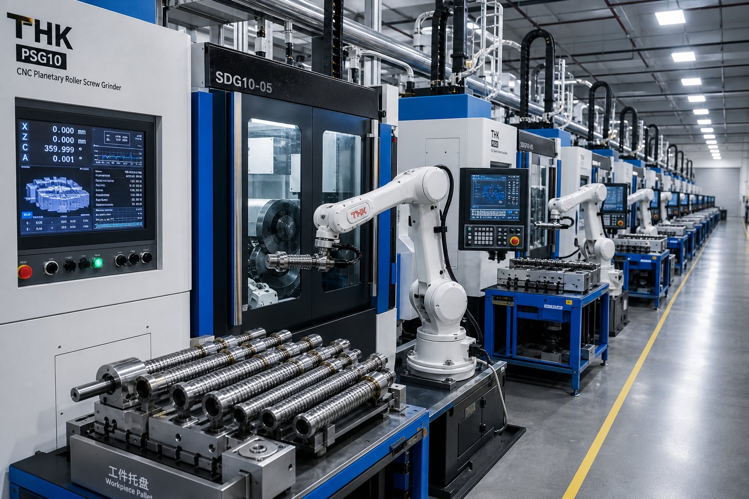
Scaling Production and Sourcing Precision Planetary Roller Screw Components
A manufacturer who grinds flawless threads on ten prototype shafts does not automatically scale that quality to ten thousand. Volume changes everything -- the machines, the fixturing strategy, the economics of each thread production method, and the quality systems required to keep every unit inside tolerance when human attention per part shrinks by orders of magnitude. For engineers and procurement teams evaluating a planetary roller screws company, understanding how production scales -- and where it breaks -- is just as critical as understanding the machining processes themselves.
Scaling from Prototype to Series Production
Prototype quantities forgive slow methods. A single screw shaft can be wire-EDM cut, single-point ground, and hand-inspected with a CMM scan that takes twenty minutes per part. That approach delivers exquisite accuracy -- and utterly impractical cycle times for anything beyond a handful of units. Scaling demands a deliberate transition through manufacturing tiers, each one trading individual attention for repeatable process control.
At low volumes -- typically one to fifty units -- thread profiles are often generated entirely by grinding from solid, with each component receiving individual dimensional verification. Dedicated fixturing may not exist yet; operators use universal chucks, collets, and adjustable workholding. Ring gears might be wire-EDM cut because hobbing dies are not justified. Some engineering teams even explore planetary roller screw 3D print approaches for carrier cages or non-load-bearing structural elements during early prototyping, using metal additive manufacturing to validate geometry before committing to production tooling.
Medium-batch production -- fifty to a few thousand units -- justifies dedicated fixturing, thread whirling for semi-finishing before final grinding, and batch heat treatment with documented furnace recipes. Grinding wheel specifications are locked down, dressing intervals are standardized, and SPC begins tracking critical dimensions across production runs rather than inspecting every part individually. This is the volume tier where most industrial planetary roller screw products are manufactured today -- servo press actuators, injection molding drives, and general automation axes.
High-volume production reshapes the entire process chain. Thread rolling lines with automated bar feeding handle screw shaft blanks at cycle times measured in seconds rather than minutes. Automated loading and unloading systems move components between grinding centers without operator handling. In-process gauging becomes continuous rather than periodic, feeding offset corrections directly into CNC controls. Roller sorting systems use automated measurement stations to group rollers into matched diameter bands at production speed.
This high-volume tier is where explosive demand growth is headed. The planetary roller screw humanoid robot application illustrates the scale challenge vividly: each humanoid requires 14 to 40+ actuators, and with industry projections pointing toward hundreds of thousands of robot shipments by 2030, demand for planetary roller screws in robotics could reach millions of units annually. At current planetary roller screw price levels -- $1,350 to $2,700 per unit according to industry analysts -- the economic pressure to scale efficiently is enormous. Companies that solve the precision-at-volume manufacturing challenge will not just capture market share; they will determine how quickly the entire robotics ecosystem can grow.
Established manufacturers like Ewellix planetary roller screws have invested heavily in automated production infrastructure for standard product ranges. For custom configurations, smaller specialized producers often offer faster development cycles and more flexible engineering support -- but their scalability may be limited by equipment capacity. The right sourcing decision depends on matching the supplier's production tier to your application's volume trajectory, not just today's order quantity.
Sourcing Precision Planetary Screw Components
Every chapter in this guide has built toward a single practical question: how do you identify a manufacturer whose process control matches your performance requirements? Catalog specifications describe design intent. Manufacturing infrastructure determines whether that intent becomes reality in every unit shipped. When evaluating a planetary roller screws company for sale inquiries or long-term supply agreements, the following criteria separate capable producers from those who merely assemble purchased components:
- In-house process breadth: Does the manufacturer control thread grinding, heat treatment, surface finishing, and assembly under one roof? Outsourcing any of these critical steps fragments accountability and introduces inter-facility tolerance stack-ups that erode consistency.
- Demonstrated precision class capability: Can the supplier provide Cpk data -- not just tolerance claims -- for the precision class your application requires? Ask for SPC trend charts spanning at least three months of production on comparable components.
- Material traceability and certification: For aerospace and defense applications, full material traceability from mill certificate through finished assembly is non-negotiable. Verify that the supplier maintains documented incoming material inspection protocols including spectrographic analysis and hardness verification.
- Inspection equipment depth: Look beyond the final test bench. A capable manufacturer owns optical profilometers for thread form verification, dedicated lead measurement machines, surface roughness instruments with appropriate cutoff settings for thread flanks, and Barkhausen noise analyzers or nital etch capability for grinding burn detection.
- Assembly and preload methodology: Evaluate the supplier's fixturing for roller phasing, their preload measurement approach (calibrated load cell versus estimated torque), and whether every unit receives documented functional testing including running torque, backlash, and efficiency verification.
- Volume scalability roadmap: A supplier building ten prototype units may not have the automation infrastructure to deliver ten thousand per year at the same quality level. Understand their equipment capacity, automation plans, and whether their quality systems scale with volume or collapse under it.
- Cross-domain manufacturing expertise: Manufacturers whose precision threading capabilities extend across related product families -- not just a single assembly type -- demonstrate deeper process maturity. Their grinding, heat treatment, and inspection infrastructure has been validated against a broader range of geometries and materials.
That last criterion deserves emphasis. The same thread-grinding accuracy, heat treatment control, and quality inspection rigor that define planetary roller screw production apply directly to related precision screw domains. For engineering teams whose research extends into plasticizing, mixing, or polymer dispersion applications, manufacturers with cross-domain capability offer a distinct advantage. NANHAIYA's planetary screw barrel product line, for example, applies these same manufacturing disciplines -- precision thread grinding, controlled case hardening, and rigorous dimensional verification -- to planetary screw barrel components used in extrusion and compounding systems. For teams evaluating custom planetary screw structures across both linear motion and polymer processing applications, that shared manufacturing foundation reduces qualification risk and consolidates supplier relationships.
Ultimately, the planetary roller screw price you pay reflects the manufacturing infrastructure behind it. A quote significantly below market average almost certainly signals shortcuts -- inferior steel grades, fewer grinding passes, outsourced heat treatment, or assembly without functional testing. Total cost of ownership over a five-to-ten-year service horizon -- accounting for unplanned downtime, replacement frequency, and maintenance burden -- consistently favors suppliers who invest in manufacturing control rather than competing on initial unit cost alone. The knowledge built throughout this guide gives you the framework to distinguish between the two.
Frequently Asked Questions About Planetary Roller Screw Manufacturing
1. What materials are used to manufacture planetary roller screws?
Planetary roller screws primarily use three steel alloy families. Bearing steels like AISI 52100 (100Cr6) are favored for screw shafts and rollers because they through-harden to HRC 60-64, delivering exceptional rolling contact fatigue strength. Case-hardening steels such as 16MnCr5 and 20MnCr5 are chosen for nuts and ring gears, where a hard outer case (HRC 58-62) over a tough core (HRC 30-40) absorbs shock loads without brittle fracture. Through-hardening tool steels like D2 appear in specialty or heavy-duty applications requiring extreme wear resistance. The alloy selected for each component directly determines heat treatment strategy, grinding parameters, achievable surface hardness, and final dimensional tolerances throughout the entire manufacturing chain.
2. How are planetary roller screw threads manufactured?
Three dominant methods produce planetary roller screw threads, each suited to different precision and volume requirements. Precision thread grinding uses CBN or aluminum oxide wheels on fully hardened steel to achieve lead errors below 2-3 micrometers per pitch and surface finishes of Ra 0.2-0.4 micrometers -- the standard for aerospace and robotics applications. Thread whirling is a faster soft-state process that generates near-net thread forms before heat treatment, leaving 0.05-0.15 mm of stock for final grinding. Thread rolling cold-forms threads at 5-10x the speed of cutting, producing superior surface finishes (Ra 0.02-0.10 micrometers) with work-hardened flanks, but it is limited to materials below approximately 36 HRC and cannot replicate complex Gothic arch profiles at micro-scale roller diameters. Many manufacturers combine whirling for roughing with grinding for finishing to balance cost and accuracy.
3. Why is the planetary roller the most difficult component to manufacture?
Planetary rollers typically measure only 3 to 8 millimeters in diameter, yet each must carry a thread profile matching the screw shaft with sub-micrometer geometric fidelity. At this scale, conventional fixturing methods fail -- standard chucks would either crush the part or allow deflection that destroys accuracy. Production relies on CNC Swiss-type lathes with guide bushings for blank preparation, followed by thread grinding on dedicated small-diameter machines where even minor thermal expansion during grinding pushes the thread form outside tolerance. The critical challenge extends beyond individual roller accuracy: roller-to-roller dimensional consistency across every roller in an assembly directly determines load sharing. A roller just 2-3 micrometers oversize relative to its neighbors carries disproportionate load, accelerating wear and cascading failure through the entire mechanism.
4. What precision classes exist for planetary roller screws, and how do they affect cost?
Planetary roller screw precision classes range from standard transport grade (lead accuracy of plus or minus 50-100 micrometers per 300 mm) to ultra-high precision (below plus or minus 5 micrometers per 300 mm). Each step up in class does not simply tighten tolerance numbers -- it adds manufacturing operations and inspection steps. A standard-class shaft might move from thread rolling directly to assembly, while an ultra-high-precision shaft passes through whirling, heat treatment, rough grinding, in-process lead measurement, finish grinding with gauging feedback, superfinishing, and full CMM verification. This escalating process chain makes precision class the primary cost driver. Engineers should specify only the class their application genuinely requires, since over-specifying precision multiplies manufacturing cost without adding functional value.
5. How do you evaluate a planetary roller screw manufacturer's quality capability?
Look beyond catalog specifications and ask for process evidence. Key evaluation criteria include in-house control of thread grinding, heat treatment, surface finishing, and assembly under one roof; Cpk data spanning at least three months of production on comparable components rather than simple tolerance claims; full material traceability with documented spectrographic analysis and hardness verification at incoming inspection; dedicated inspection equipment including lead measurement machines, optical profilometers for thread form verification, and surface roughness instruments with appropriate cutoff settings for thread flanks; and documented assembly procedures covering roller phasing fixtures, calibrated preload measurement, and functional testing of every unit for running torque, backlash, and efficiency. A manufacturer who can walk through each step with supporting data demonstrates process control maturity that catalog claims alone cannot verify.
Written by
Nanhaiya Technical Team
Zhoushan Nanhaiya Plastic Machinery Co., Ltd.
The Nanhaiya technical team supports screw and barrel manufacturing projects through application review, technical communication, custom manufacturing coordination, and production and quality control.
Discuss Your Application
Related Articles
More insights on screw barrel technology and plastics processing.
PVC Pipe Making Machine: What No Supplier Will Tell You First
Oct 21, 2026
Learn what a PVC pipe making machine really includes, how each component works, extruder types compared, maintenance schedules, defect fixes, and buying tips.
Read Article
What Your Film Extrusion Machine Datasheet Won't Tell You
Oct 20, 2026
Film extrusion machine guide covering blown vs cast processes, multilayer configurations, screw specs, resin selection, and supplier evaluation for production engineers.
Read Article
Raw Scrap to Perfect Pellets: Plastic Pelletizing Machine Guide
Oct 19, 2026
Learn how a plastic pelletizing machine converts scrap into uniform pellets. Covers cutting methods, extruder types, quality control, costs, and maintenance.
Read ArticleLooking for something else?
Search by material, symptom or product and jump straight to the relevant page.
These are navigation suggestions based on keyword matching — not a quotation, not a delivery commitment, and not a substitute for engineering review. Final specification is confirmed by our engineers against your drawings and processed material.
Need help with screw barrel selection?
Share your machine model, processed material and application. Our team can help with pricing and technical support.