

What Is a Lab Scale Twin Screw Extruder and Why It Matters
Imagine you have a promising new polymer blend on paper, but committing hundreds of kilograms of raw material to a production-scale trial feels like a gamble. That is exactly the scenario a lab scale twin screw extruder is built to solve. It gives researchers the power to compound, mix, and process materials at a fraction of the volume - and a fraction of the risk.
What Defines a Lab Scale Twin Screw Extruder
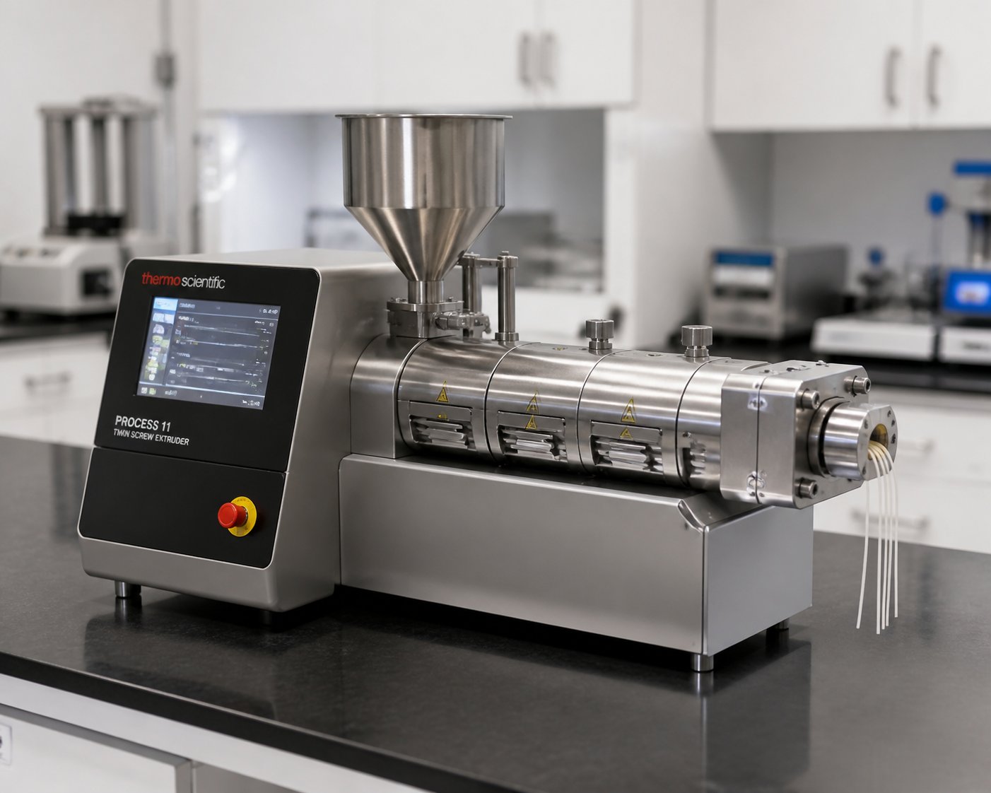
A lab scale twin screw extruder is a compact, benchtop-friendly processing machine that uses two intermeshing screws to convey, melt, mix, and shape materials in small batches. It is purpose-built for R&D environments where precision matters more than throughput.
A lab scale twin screw extruder is a compact extrusion system featuring screw diameters typically between 10 mm and 30 mm, capable of processing material at rates from a few grams to low kilograms per hour. It is designed for benchtop or small lab station use, enabling researchers to develop formulations, test material behavior, and generate scale-up data with minimal raw material consumption.
What separates this class of equipment from its larger counterparts? Several concrete factors stand out. Screw diameters generally fall in the 10-30 mm range, keeping the overall machine footprint small enough for a standard laboratory bench. Throughput is measured in grams to a few kilograms per hour rather than hundreds of kilograms. Power requirements are modest - think standard electrical outlets rather than dedicated industrial feeds. And perhaps most importantly, a benchtop twin screw extruder can often be operated by a single researcher, making it ideal for university labs, pharmaceutical development groups, and small R&D teams working with expensive or limited-availability materials.
Lab Scale vs Pilot Scale vs Production Scale at a Glance
Understanding where a lab scale extruder fits in the broader equipment landscape helps you make smarter purchasing and experimental decisions. Each scale serves a distinct purpose in the journey from concept to commercial product.
| Parameter | Lab Scale | Pilot Scale | Production Scale |
|---|---|---|---|
| Screw Diameter Range | ~10-30 mm | ~30-60 mm | ~60-200+ mm |
| Typical Throughput | Grams to low kg/hr | Tens of kg/hr | Hundreds to thousands of kg/hr |
| Approximate Footprint | Benchtop or small lab station | Dedicated floor space, small room | Full production floor or plant |
| Operator Requirements | 1 researcher | 1-2 trained operators | Full operations team |
| Primary Use Case | Formulation screening, process development, academic research | Process validation, scale-up trials, pre-production batches | Commercial manufacturing, continuous output |
Why do researchers, university labs, and small-batch processing teams consistently gravitate toward the lab-scale end of this spectrum? Three reasons keep coming up. First, minimal material waste - when you are working with novel biopolymers or costly pharmaceutical-grade ingredients, running experiments at grams-per-hour saves a significant amount of money. Second, rapid iteration - swapping screw configurations, adjusting barrel temperatures, and testing new additive levels can happen within a single workday rather than requiring scheduled downtime on a production line. Third, full process control - a twin-screw extruder at lab scale lets you isolate and study individual process variables with a level of precision that larger machines simply cannot match.
This combination of low material consumption, fast turnaround, and granular control is what makes the lab scale extruder not just a miniaturized version of a bigger machine, but a dedicated research instrument. The real question, though, is what happens inside those two screws that makes twin screw extrusion so effective in the first place - and that comes down to some elegant engineering mechanics.
How Twin Screw Extrusion Works and Core Mechanics Explained
Two screws rotating inside a barrel might sound straightforward, but the physics driving the twin screw extrusion process are what separate this technology from every other continuous mixing method available. Understanding these mechanics is not just academic trivia - it directly shapes how you design experiments and interpret results on your lab equipment.
Intermeshing Geometry and Self-Wiping Action
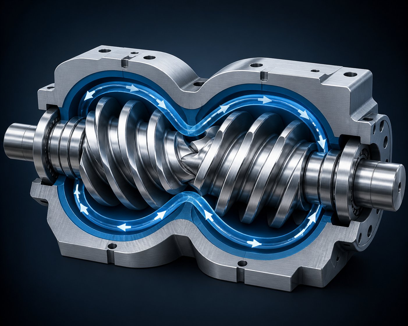
Picture two screws positioned side by side inside a figure-eight-shaped barrel bore. The flights of one screw reach into the channel of the other - this is the intermeshing zone, and it is where the real magic happens. The intermeshing geometry creates a positive conveying action that physically pushes material forward rather than relying solely on frictional drag against the barrel wall.
Even more important is the self-wiping behavior this geometry produces. In a corotating twin screw configuration, the surface velocities at the intermesh point move in opposite directions, causing material to be transferred from one screw to the other in a figure-eight pattern along the length of the barrel. No polymer sits idle. No dead zones form. Material that might otherwise stagnate and degrade gets continuously swept forward, which is especially critical when you are processing heat-sensitive experimental formulations.
This self-wiping effect also enforces a first-in, first-out flow sequence that produces a defined residence time distribution (RTD). Why does RTD matter for your experiments? Because a narrow, predictable RTD means every particle of your formulation experiences a nearly identical thermal and mechanical history. The result is superior experimental reproducibility - run the same parameters twice, and you get the same product twice. The degree of screw fill directly influences this distribution: more filled screws yield a tighter RTD, while starved conditions widen it.
How Twin Screws Generate Mixing and Conveying Forces
Inside the barrel, three fundamental flow mechanisms work simultaneously to move and mix material during twin screw extrusion:
Drag flow is the primary conveying mechanism. The rotating screw surfaces grip the polymer melt and pull it forward along the channel. Think of it as the engine that keeps material progressing toward the die.
Pressure flow works in the opposite direction. Whenever material encounters a restriction - a kneading block, a reverse element, or the die itself - pressure builds and drives some material backward against the conveying direction. This back-and-forth interplay is actually beneficial because it increases the mixing exposure each particle receives.
Leakage flow occurs in the tiny gaps between screw flights and the barrel wall, and between the two screws themselves. Material passing through these narrow clearances experiences intense shear, contributing to dispersive mixing. A cross-sectional analysis of any twin screw reveals five distinct shear regions - from the low-shear channel center to the high-shear overflight gap between screw tip and barrel wall - each contributing differently to the overall mixing result.
The ability to modulate shear intensity is one of the most powerful capabilities researchers gain with twin screw equipment. By adjusting screw RPM, selecting different element geometries, and controlling barrel temperatures to manage melt viscosity, you can dial in precisely the shear rate your material needs. Processing a shear-sensitive pharmaceutical compound? Run gentler distributive mixing elements at lower speeds. Need to break up stubborn filler agglomerates in a polymer blend? Deploy aggressive kneading blocks at higher RPMs. This level of control is why the twin screw dominates mixing-intensive research applications.
Compared to single-screw systems - where polymer tends to stay in relatively the same radial position within the channel, limiting turnover - twin screw designs offer a fundamentally different mixing paradigm. The key advantages include:
- Superior mixing homogeneity: Full channel-to-channel material transfer between screws ensures every particle gets uniformly processed, unlike single-screw channels where stratified velocity profiles leave portions of the melt under-mixed.
- Self-wiping capability: Eliminates dead zones and material stagnation, reducing degradation risk and ensuring consistent residence time across the melt.
- Flexible screw configuration: Modular, segmented screw elements can be rearranged to create virtually limitless combinations of conveying, mixing, and back-pressure zones tailored to each experiment.
- Better feeding consistency: Starve-fed operation decouples feed rate from screw speed, giving researchers independent control over throughput and mixing intensity simultaneously.
These mechanical advantages are not merely theoretical - they translate directly into the kind of experimental flexibility and data quality that lab-scale research demands. Yet the real depth of that flexibility only becomes clear when you understand what each specification on an extruder data sheet actually controls and why it matters for your specific application.
Key Technical Specifications Every Researcher Should Understand
Open a manufacturer's data sheet for any laboratory twin screw extruder and you will encounter a dense cluster of numbers - diameters, ratios, torque ratings, RPM ranges, zone counts. Individually, each figure tells you something useful. Together, they define the operational boundaries of your experiments and determine whether a particular screw extruder can actually handle the materials and processes you have planned. The problem is that most spec sheets assume you already know what each parameter means in practice. Let's fix that.
Screw Diameter and L/D Ratio Demystified
Screw diameter is the single most defining specification of any laboratory extruder. It sets the throughput ceiling, dictates the available free volume inside the barrel, and directly influences how much material you need per experimental run. For lab-scale units, screw diameters typically range from roughly 10 mm to 30 mm. A comprehensive review in AAPS PharmSciTech notes that pharmaceutical R&D efforts are commonly performed on twin screw extruders with screw outside diameters in the 10-30 mm range, with flight depths as small as 1 to 3 mm on smaller machines.
Why does this matter for your work? Smaller diameters - say 10 to 16 mm - let you run meaningful experiments with as little as a few hundred grams of raw material. That is a significant advantage when your formulation includes an expensive active pharmaceutical ingredient or a novel biopolymer available only in limited quantities. Larger lab-scale diameters around 20 to 30 mm increase throughput capacity and can bridge the gap toward pilot-scale trials, but they require proportionally more material per run.
Then there is the L/D ratio, or length-to-diameter ratio. This value is calculated by dividing the total length of the processing section by the screw diameter. If a laboratory twin screw extruder has a 20 mm screw diameter and an 800 mm processing length, the L/D ratio is 800 divided by 20, or 40:1. Cut that processing length to 400 mm and the L/D drops to 20:1.
What does this ratio actually control? Think of it as a measure of how much processing real estate you have available. A higher L/D ratio means a longer barrel, which translates into more room for barrel zones and screw element combinations. You can fit additional mixing sections, venting ports, side-feeding locations, and cooling zones along the processing length. For complex formulations that demand multiple sequential operations - melting, mixing, venting, downstream ingredient addition, and final pumping - a 40:1 or 48:1 L/D provides the flexibility to stage all those operations without crowding.
Conversely, a shorter L/D such as 20:1 or 24:1 works well for simpler processes that only require basic compounding and discharge. It also means shorter residence time, which can be an advantage for highly heat-sensitive materials that degrade with prolonged thermal exposure. The key takeaway: L/D ratio is not a "bigger is better" metric. It is a process-matching decision that balances residence time, processing flexibility, and material sensitivity.
Torque, RPM, and Barrel Zone Configuration
If screw diameter and L/D ratio define the geometry of your processing space, torque and RPM define the energy and speed you can put into your material.
Torque represents the rotational force the motor and gearbox can deliver to the screws. In practical terms, torque limits determine the maximum viscosity of materials you can process. High-viscosity polymers, heavily filled compounds, and formulations with large proportions of solid additives all demand significant torque to convey and mix effectively. If your extruder's torque capacity is too low for the material, you will see motor overloads, inconsistent output, or simply an inability to process the formulation at all. The torque transmission chain - from motor through gearbox to screw shafts - is often the limiting factor for power available to process materials, especially on segmented-screw designs where shaft cross-section constrains maximum load.
Maximum RPM controls how fast the screws rotate, and by extension, the shear rate imposed on the material. Higher RPM generates more shear and reduces residence time. Lower RPM reduces shear intensity and extends how long material spends in the barrel. This is not just about speed - it is about process control. When you are working with a shear-sensitive pharmaceutical blend, running at a lower RPM with gentle mixing elements protects the active ingredient from degradation. When you need to break down agglomerates in a filled compound, higher RPM with aggressive kneading blocks delivers the dispersive energy required. The ability to decouple RPM from feed rate in a starve-fed system makes this control even more precise: you adjust screw speed for mixing quality independently of how much material you are feeding per hour.
Barrel zone configuration is the third pillar of process control, and it is one that often gets overlooked during initial equipment evaluation. Each barrel zone is an independently heated and cooled segment of the barrel, typically 4 to 5 L/D in length per zone. Heating is commonly achieved via cartridge heaters embedded in the barrel body, while cooling uses internal bores for liquid circulation or, on simpler designs, external air blowers.
Why does the number of zones matter? More zones give you finer temperature profiling along the length of the extruder. Imagine you need a gradual temperature ramp in the feed section to prevent premature melting, a high-temperature mixing zone for thorough plastication, and a cooled metering zone before the die to manage melt viscosity. With only three or four zones, you are painting with broad strokes. With six, eight, or more zones, you can sculpt the temperature profile with precision - holding each section within tight tolerances and responding quickly to process changes. For experimental work where you are isolating the effect of temperature on formulation performance, this granularity is indispensable.
The table below consolidates these key specifications into a single reference. Rather than listing specific numbers that vary by manufacturer, it explains what each parameter controls and why it matters for your research decisions.
| Specification Parameter | What It Controls | Why It Matters for Lab-Scale Research |
|---|---|---|
| Screw Diameter | Throughput capacity, free volume, and minimum batch size | Determines how much material you need per experiment; smaller diameters conserve expensive or scarce raw materials |
| L/D Ratio | Available processing length for staging unit operations (mixing, venting, feeding, pumping) | Higher ratios accommodate complex multi-step processes; lower ratios suit simpler formulations and limit residence time for heat-sensitive materials |
| Maximum RPM | Shear rate and residence time; decoupled from feed rate in starve-fed operation | Enables shear intensity control - critical for balancing mixing quality against degradation risk in experimental formulations |
| Torque | Maximum processable material viscosity and filler loading | Sets the upper boundary for the toughest materials you can run; insufficient torque causes overloads and limits formulation range |
| Number of Heating/Cooling Zones | Temperature profiling resolution along the barrel length | More zones provide finer thermal control, enabling precise isolation of temperature effects during formulation studies |
| Throughput Range | Minimum and maximum material feed rates achievable with consistent process stability | Defines the experimental window - too low and feeding becomes unreliable; too high and you waste material on screening runs |
One detail worth highlighting: these parameters do not exist in isolation. Torque, RPM, and barrel temperature interact dynamically during every run. A high-viscosity melt demands more torque at any given RPM, and raising barrel temperature reduces viscosity, which in turn reduces torque demand. Understanding these interdependencies is what separates a researcher who simply operates a laboratory extruder from one who truly controls the process.
Specifications tell you what the machine can do. But the way those two screws rotate relative to each other - co-rotating or counter-rotating - determines the fundamental character of the mixing and conveying forces at play, and that choice shapes everything from shear intensity to pressure generation.
Co-Rotating vs Counter-Rotating Screws for Lab Applications
You know the specs. You understand the flow mechanics. But before you run your first experiment, one fundamental design decision will shape every result you collect: do the two screws rotate in the same direction, or in opposite directions? This is not a minor engineering footnote. The rotation configuration of a co rotating and counter rotating twin screw extruder determines shear intensity, mixing quality, pressure generation, and even the range of materials you can process reliably. Choosing the wrong one means fighting the machine instead of letting it work for you.
Co-Rotating Twin Screws and Their Research Advantages
In a co rotating twin screw extruder, both screws turn in the same direction - typically toward each other at the top of the barrel. This seemingly simple arrangement produces a cascade of processing advantages that have made it the dominant configuration in research and development labs worldwide.
The most significant advantage is what happens at the intermesh zone. Because the screw surfaces move in opposite directions at the point where they meet, material is actively transferred from one screw to the other in a continuous figure-eight pattern. This motion generates strong shear stress between the screws, driving both dispersive and distributive mixing simultaneously. Stubborn filler agglomerates get broken apart. Polymer blend domains get stretched, folded, and redistributed. The result is a level of mixing homogeneity that single-screw systems or even counter-rotating designs struggle to match.
Equally important is the self-wiping capability this geometry provides. The flight tip of one screw continuously sweeps the root of the other, preventing material from stagnating on any surface. Imagine processing a heat-sensitive pharmaceutical compound - the last thing you want is a pocket of material sitting against a hot barrel wall for minutes, degrading and contaminating the rest of your batch. Self-wiping eliminates those dead zones entirely. As Technovel notes, the fully intermeshing co-rotating design "automatically scrapes off material that adheres to the screw surface and to the inside of the barrel," suppressing gelation and thermal degradation while maintaining stable heat transfer efficiency.
These characteristics explain why co-rotating parallel twin screw extruder designs dominate three major research areas:
- Polymer compounding research: High shear and thorough distributive mixing are essential for developing new polymer blends, nanocomposites, and filled systems where uniform additive dispersion defines product quality.
- Reactive extrusion studies: The balance between shear intensity and residence time control allows researchers to promote chemical reactions - grafting, crosslinking, chain extension - while avoiding chain scission from excessive energy input.
- Hot-melt pharmaceutical extrusion: Self-wiping prevents active ingredient degradation from material stagnation, and the narrow residence time distribution ensures every particle of the formulation receives a consistent thermal and mechanical history.
When Counter-Rotating Configuration Makes Sense
Counter-rotating screws turn in opposite directions - one clockwise, the other counterclockwise. The flow behavior this creates is fundamentally different from co-rotating designs. Instead of the vigorous channel-to-channel material transfer that co-rotating screws produce, counter-rotating screws create a calender-like effect in the intermesh region. Material gets squeezed between the screws in a more contained, pressurized manner.
The practical consequence? Lower shear stress than the co-rotating type, which is actually desirable for materials where heat generation from shear should be avoided - think PVC dry blends, certain thermoset precursors, or formulations where preserving molecular weight is critical. The calender-like flow also generates higher localized pressure, making counter-rotating configurations effective for applications that demand significant die pressure without relying on high-shear mixing elements.
A specialized subset worth knowing is the conical twin screw extruder. Unlike parallel designs where both screws share the same diameter from feed to discharge, conical machines feature screws that taper from a larger diameter at the feed end to a smaller diameter at the output. This geometry provides two practical benefits: a large feed opening that accepts bulky, low-bulk-density materials more easily, and natural compression along the barrel length that builds pressure progressively. Conical designs appear most often in profile extrusion trials and PVC processing, where gentle conveying and consistent pressure matter more than intensive mixing.
The table below puts these differences side by side so you can see the trade-offs at a glance.
| Parameter | Co-Rotating | Counter-Rotating |
|---|---|---|
| Mixing Intensity | High - strong dispersive and distributive mixing from channel-to-channel material transfer | Moderate - gentler mixing with less aggressive material turnover |
| Shear Level | High - large shear stress generated at the intermesh zone | Lower - reduced shear stress, less viscous heat generation |
| Self-Wiping Capability | Excellent - continuous flight-to-root wiping eliminates dead zones | Limited - less effective self-cleaning, higher risk of material stagnation |
| Pressure Generation | Moderate - relies on downstream restriction elements and die design for pressure buildup | High - calender effect in intermesh zone generates strong localized pressure |
| Typical Lab Applications | Polymer compounding, reactive extrusion, hot-melt pharmaceutical extrusion, nanocomposite development | PVC processing, profile extrusion trials, gentle conveying of shear-sensitive formulations, pressure-demanding die experiments |
Choosing the Right Configuration for Your Experiment
Sounds like co-rotating wins every time? Not quite. The right choice depends entirely on what you are trying to accomplish with your lab scale twin screw extruder. A co-rotating machine excels when mixing quality is the primary concern - and for the majority of R&D applications, it is. But forcing a co-rotating design into a role that demands gentle, high-pressure conveying creates unnecessary process challenges.
Here is a practical guide matching common research objectives to the configuration best suited to deliver results:
- Polymer blend development and nanocomposite compounding: Co-rotating - high shear breaks down agglomerates and distributes minor-phase domains uniformly.
- Reactive extrusion (grafting, crosslinking, chain extension): Co-rotating - precise control of shear and residence time enables reaction promotion without polymer degradation.
- Hot-melt pharmaceutical extrusion and amorphous solid dispersion screening: Co-rotating - self-wiping protects active ingredients from thermal degradation caused by stagnation.
- Masterbatch and color concentrate development: Co-rotating - distributive mixing ensures pigment and additive uniformity at low loading levels.
- PVC dry-blend processing and rigid profile trials: Counter-rotating - lower shear prevents PVC degradation while generating the die pressure needed for profile extrusion.
- Shear-sensitive material evaluation: Counter-rotating - reduced viscous heat generation preserves molecular weight and material integrity.
- Low-bulk-density powder feeding trials: Counter-rotating conical - tapered feed section accommodates fluffy materials and builds compression gradually.
For most researchers purchasing their first lab-scale machine, a co-rotating configuration covers the broadest range of experimental needs. The fully intermeshing co-rotating compounding extruder has become the mainstream precisely because it delivers the best combination of mixing performance, self-cleaning reliability, and process flexibility. Counter-rotating models serve real and important purposes, but they occupy a narrower application niche - one that typically becomes relevant only when specific material constraints or processing goals demand it.
Of course, choosing between co-rotating and counter-rotating is only half the configuration story. The real granularity of process control lives in the individual screw elements themselves - the conveying segments, kneading blocks, and reverse elements that you arrange along the shaft to build a processing profile tailored to each unique experiment.
Screw Element Configuration and Modular Design Principles
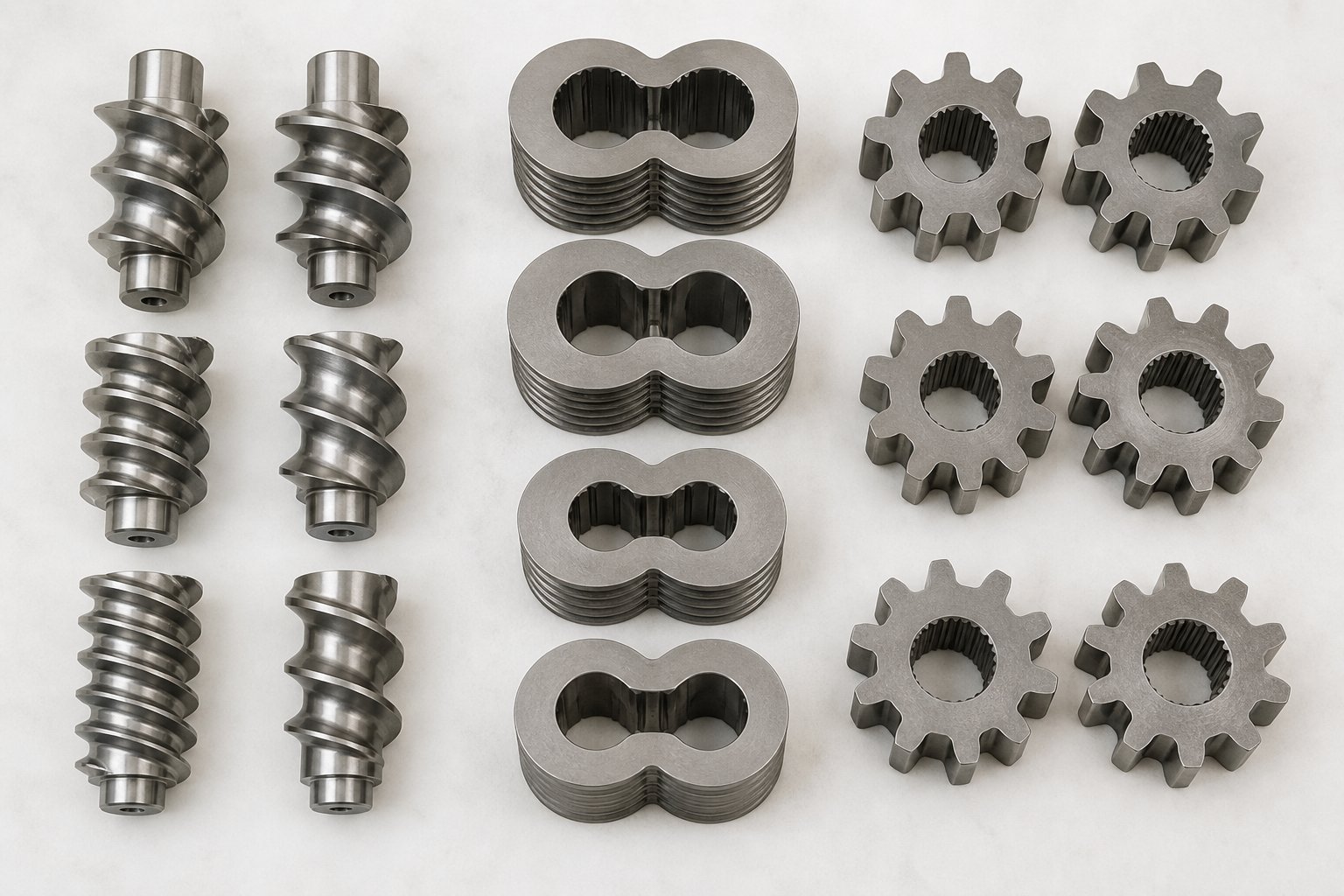
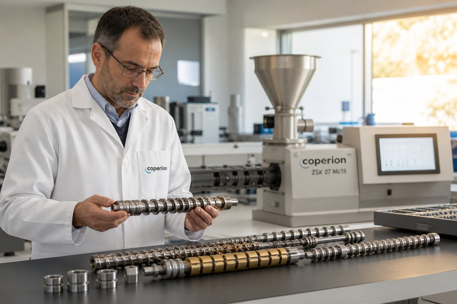
Here is a concept that changes how you think about your lab scale twin screw extruder: the screws are not fixed, monolithic shafts. They are assembled from individual, interchangeable segments - each one performing a distinct job - that slide onto a common splined shaft like building blocks. Swap one segment for another, rearrange the sequence, and you fundamentally change how the machine processes your material. This modular architecture is what makes twin screw extruders true research instruments rather than one-trick production tools. And yet, it is one of the most overlooked topics when researchers evaluate equipment.
Understanding Modular Screw Elements and Their Functions
Every extruder screw configuration is built from a handful of element families, each engineered to do something specific to the material passing through it. Think of them as the vocabulary of your process - the more fluently you understand each element type, the more precisely you can "speak" to your material.
Conveying elements are the workhorses. Shaped like traditional helical flights, they grip material and push it forward along the barrel. Their primary variable is pitch - the axial distance between consecutive flights. Larger pitch moves material faster with less compression, which is ideal for the feed zone where you need to accept incoming pellets or powder without jamming. Smaller pitch slows material down, increases compression, and builds pressure - useful near the die where consistent output matters. While conveying elements do generate some shear as material slides along the helical channel, they are not designed as primary mixing tools. Their real contribution is controlling fill level and pressure development along the barrel, which directly influences how every downstream element performs.
Kneading blocks are where the serious mixing happens. Picture a series of elliptical discs stacked on the shaft, each offset from the previous one by a defined stagger angle. Three design variables control their behavior: disc width, the number of discs in the block, and that stagger angle. Narrower discs create more frequent flow disruptions and higher local pressure fluctuations, boosting dispersive mixing - the kind that breaks apart stubborn filler agglomerates. Wider discs produce smoother flow and gentler distributive mixing, spreading components evenly without imposing extreme stress. Low stagger angles promote forward pumping with moderate shear, while high stagger angles reduce net throughput, increase back-mixing, and significantly ramp up shear intensity. This tunability is what makes kneading blocks the most powerful mixing tools in any twin screw system.
Kneading blocks also come in three orientations that further expand your options:
- Forward kneading blocks: Provide a net positive conveying action while delivering strong mixing. Useful when you need shear without sacrificing too much throughput.
- Neutral kneading blocks: Have nearly zero net conveying capacity, causing material to oscillate back and forth. This dramatically increases residence time and back-mixing in the local zone - ideal for intensive mixing stages.
- Reverse kneading blocks: Push material backward against the overall flow direction, creating strong pressure buildup upstream and generating high-stress, long-residence-time conditions. These are particularly effective for high-intensity dispersive mixing and creating melt seals for devolatilization.
Distributive mixing elements take a different approach. Rather than imposing brute-force shear, they repeatedly split, stretch, and recombine the melt flow. Examples include gear-shaped elements, turbine mixing elements, and interrupted conveying elements with offset channels. These are your go-to choice when you want to spread colorants, additives, or minor-phase polymers evenly throughout the melt without generating excessive heat - a frequent requirement for heat-sensitive formulations.
Reverse conveying elements (also called left-handed or back-conveying elements) function like speed bumps in your process. Placed strategically, they push material backward and force the upstream zone to fill completely, building pressure and extending residence time in the preceding section. Researchers use them to create melt seals ahead of vent ports - ensuring gases can escape without melt following them out - and to increase fill level before mixing zones so kneading blocks encounter a continuous melt phase rather than partially filled, inconsistent material.
Designing a Screw Configuration for Different Experiments
Knowing what each element does is one thing. Sequencing them into a coherent configuration that matches your experimental goals is where the real skill lies. Fortunately, there is a general logic that applies across most applications on a lab scale twin screw extruder. Think of it as a recipe template that you then customize for each specific material and process objective.
- Feed zone - large-pitch conveying elements: The screw section directly below the hopper uses wide-pitch conveying elements to grip incoming material and move it forward without restriction. As Granuwel's screw configuration principles note, a large lead in the feeding section ensures a large screw groove volume that can accommodate pellets, powders, or fibrous additives smoothly. Cramping this zone with tight-pitch elements or premature kneading blocks is a recipe for bridging and feed instability.
- Melting and plasticizing zone - transitional conveying elements followed by kneading blocks: Pitch gradually decreases to compress material against the heated barrel wall, initiating melting. Forward kneading blocks then convert mechanical shear energy into thermal energy, completing the melt transition. The key is restraint - overly aggressive kneading in the melting section causes excessive temperature rise far beyond what is needed, wasting energy and risking degradation. Interspersing conveying elements between kneading blocks distributes the energy input over a longer axial distance, keeping melt temperature controlled.
- Primary mixing zone - kneading blocks and distributive mixing elements for dispersion and homogenization: This is where your formulation actually gets compounded. Kneading blocks with 45-degree and 60-degree stagger angles deliver the shear needed to disperse fillers, break down agglomerates, and blend polymer phases. Gear-shaped or turbine distributive elements can supplement kneading blocks when you want thorough spatial distribution without piling on more shear stress. Conveying elements should still be interspersed here - continuous runs of kneading blocks without conveying breaks cause excessive shearing and can spike torque beyond safe limits.
- Venting zone - reverse elements for melt sealing, large-pitch conveyors for degassing: If your process requires devolatilization, a reverse element or reverse kneading block upstream of the vent port creates a pressure seal that prevents melt from exiting the vent. Directly beneath the vent, large-pitch conveying elements reduce fill level, creating a thin melt layer with maximum exposed surface area for moisture and volatile removal.
- Metering zone - progressively tighter conveying elements for consistent output: The final section uses conveying elements with gradually decreasing pitch to build stable, uniform pressure at the die. This prevents surging and ensures dimensional consistency in your extrudate. Some configurations use single-flighted elements here to enhance discharge capability.
That is the general template. The real art is in how you adapt it. Consider three common research scenarios and how the extruder screw configuration shifts for each:
Polymer compounding with mineral fillers: The mixing zone gets the most attention. You will use aggressive kneading blocks - narrow discs, high stagger angles - to deliver enough dispersive force to break filler agglomerates. A reverse kneading block at the end of the mixing section increases residence time in the high-shear zone, ensuring thorough deagglomeration. The trade-off is higher melt temperature, so barrel cooling in this zone is typically set aggressively.
Hot-melt pharmaceutical extrusion: Protecting the active pharmaceutical ingredient from thermal and mechanical degradation is paramount. Kneading blocks are shorter, with wider discs and lower stagger angles that favor gentle distributive mixing over intense dispersive shear. Conveying elements make up a larger proportion of the overall configuration. Residence time is kept short and tightly distributed to ensure every particle of the formulation experiences the same thermal history - critical for reproducible amorphous solid dispersion results.
Reactive extrusion for grafting or crosslinking: Here, residence time is the key variable. The configuration includes extended mixing sections with neutral kneading blocks that hold material in high-shear zones longer, promoting the desired chemical reaction. Reverse elements downstream create additional back-pressure, further extending residence time. However, these elements must be balanced carefully against temperature rise - if the reaction is exothermic, excessive residence time combined with shear heating can push the melt past its thermal stability limit.
Screw configuration is arguably the most powerful process variable researchers control on a lab scale twin screw extruder - more influential than barrel temperature, more impactful than screw speed, and the single biggest determinant of whether a formulation succeeds or fails during development.
The beauty of modular screw extruders at lab scale is that testing a new configuration takes minutes, not days. Pull the screws, rearrange the elements, reassemble, and run. This rapid iteration capability means you can systematically isolate the effect of each element change on your product quality - building a data-driven understanding of your process rather than relying on guesswork. That same systematic approach becomes even more valuable when you move beyond screw design and consider the full landscape of applications and material challenges that lab-scale extrusion is uniquely positioned to address.
Applications and Material Considerations for Lab Scale Extrusion
Screw configurations give you the tools. Applications give you the reason to pick them up. Every element arrangement, barrel temperature profile, and RPM setting ultimately exists to solve a specific material processing problem - and the range of problems that a lab scale twin screw extruder can tackle is remarkably broad. From polymer blend development to pharmaceutical formulation screening, the common thread is always the same: researchers need answers from small quantities of material, fast turnaround, and data they can trust enough to build a scale-up strategy around.
Polymer Compounding and Material Development
Polymer compounding is where twin screw extrusion earned its reputation, and it remains the most common application for lab-scale equipment. When you are developing a new polymer blend - say, a polypropylene matrix loaded with glass fibers and a compatibilizer - you need to answer a cascade of questions before anyone commits to a production run. What filler loading gives the right balance of stiffness and impact resistance? Does the compatibilizer actually improve interfacial adhesion, or does it just add cost? What happens to mechanical properties when you push filler content from 20% to 35%?
A compounding twin screw extruder at lab scale lets you answer all of those questions in a single day. Batch sizes as small as a few hundred grams mean you can run five or six formulation variations from a single kilogram of base resin. Each run produces enough extrudate for tensile bars, impact specimens, and rheological characterization - real data from real melt-processed material, not predictions from a simulation.
This efficiency transforms the development workflow. Instead of selecting two or three candidate formulations based on educated guesses and committing them to expensive pilot-scale trials, you can screen dozens of variations at the bench. Additive packages, coupling agent levels, pigment dispersions, nucleating agent concentrations - all can be iterated rapidly on a compounding extruder sized for the lab. The result is that your pilot-scale trials become confirmation runs rather than exploration exercises, saving weeks of machine time and potentially hundreds of kilograms of raw material.
Material considerations at this scale, however, deserve careful attention. Minimum batch sizes depend on the free volume of the barrel and the screw diameter. On a 16 mm extruder, you might need at least 50 to 100 grams to achieve steady-state processing conditions and collect meaningful samples. Hygroscopic resins like nylon or PET require thorough pre-drying before feeding - moisture levels that are merely inconvenient at production scale can cause severe hydrolytic degradation in a lab-scale barrel where residence times are short but surface-to-volume ratios are high. Heat-sensitive formulations, including many bioplastics and specialty elastomers, demand precise barrel temperature control and conservative screw configurations to avoid localized overheating in the small-diameter channel.
Pharmaceutical Hot-Melt Extrusion and Specialty Applications
Pharmaceutical research has embraced twin screw extrusion with particular enthusiasm over the past decade, and much of that work begins - and often stays for extended periods - at the lab scale. The reason is straightforward: active pharmaceutical ingredients (APIs) are expensive, sometimes costing thousands of dollars per gram during early development, and they are rarely available in quantities that justify pilot-scale experiments.
Hot-melt extrusion (HME) at lab scale enables a category of pharmaceutical development work that would be impractical any other way. The most prominent example is amorphous solid dispersion (ASD) screening, where a poorly soluble drug compound is molecularly dispersed into a polymer carrier matrix to improve bioavailability. A research team at Boehringer Ingelheim demonstrated exactly this approach, using a 9 mm twin screw mini-extruder to develop and screen ASD formulations of an insoluble BCS Class II compound with batch sizes as small as 5 to 20 grams. That lab-scale work - consuming roughly 500 grams of API total - generated enough data to successfully scale the HME process to clinical batch manufacture within seven months.
Beyond ASD development, a hot melt extruder at lab scale serves several other pharmaceutical applications:
- Taste-masking studies: Bitter APIs can be coated or embedded in polymer matrices through extrusion, and lab-scale trials let formulators test multiple polymer-API combinations quickly.
- Controlled-release formulation trials: Matrix tablets and multiparticulate systems with tailored release profiles can be prototyped using minimal API quantities.
- Co-crystal and co-amorphous system formation: HME can promote in situ co-crystal formation between APIs and coformers, a process that benefits enormously from rapid screening at small scale.
The pharmaceutical space is not the only specialty area driving demand for lab-scale extrusion. Biodegradable polymer research - including PLA, PHA, and starch-based blends - relies heavily on small-batch extrusion trials because these materials are often sensitive to both temperature and shear, requiring careful process optimization before any attempt at volume production. Masterbatch development uses lab-scale extruders to dial in pigment and additive concentrations with precision. Food-grade compounding trials, especially those involving novel protein-based or plant-fiber formulations, benefit from the small batch sizes and tight process control that lab equipment provides. Reactive extrusion studies - grafting maleic anhydride onto polyolefins, crosslinking silane-modified polymers, or chain-extending recycled PET - use the extruder for polymer modification as both a reactor and a processor, demanding the kind of residence time and temperature control that only a well-configured lab-scale machine can deliver with experimental-grade precision.
Material Challenges Unique to Lab Scale Processing
Here is where theory meets friction - sometimes literally. Processing materials at lab scale introduces a set of practical challenges that production-scale operators rarely encounter, and ignoring them will compromise your data quality.
Feeding difficulties with low-bulk-density powders top the list. Imagine trying to feed a fluffy, electrostatic-prone pharmaceutical excipient or a low-density fumed silica into a 16 mm barrel opening at a rate of a few grams per minute. The powder bridges in the hopper, clumps in the feed throat, and delivers material in erratic surges rather than a smooth stream. Research published in AAPS PharmSciTech found that even with gravimetric feeders, powder feed uniformity at low throughputs was a dominant source of product variability in lab-scale extrusion - and that feeder coupling geometry and nozzle design modifications were required to reduce moisture content variability in extrudates by a full order of magnitude.
Achieving consistent starve-fed operation at low throughputs is closely related. Twin screw extruders are typically operated in starve-fed mode, where the feeder controls throughput independently of screw speed. At production scale, this works smoothly because feed rates of tens or hundreds of kilograms per hour fall comfortably within the operating range of standard gravimetric feeders. At lab scale, you might need a feed rate of 200 grams per hour or less - a regime where feeder accuracy and uniformity degrade significantly. Small fluctuations in feed rate that would be negligible at high throughput become proportionally large at low throughput, directly affecting fill level, residence time, and product consistency.
Minimum viable batch sizes present another practical constraint. You need enough material to fill the barrel, purge any previous formulation from the system, reach steady-state processing conditions, and then collect sufficient extrudate for characterization. On a very small extruder - a 9 mm unit, for example - this might require only 5 to 20 grams per run. On a larger lab-scale machine with an 18 mm screw diameter, expect to need several hundred grams at minimum. Planning your material budget around these realities prevents the frustrating situation of running out of an expensive compound mid-experiment.
Strategies for processing expensive or limited-availability materials can make the difference between a productive study and a costly dead end. Experienced researchers use sacrificial purge materials - inexpensive polymers that fill and clean the barrel before and after each experimental run - to minimize how much precious formulation is wasted on startup and shutdown. Running the extruder at the lowest stable throughput reduces material consumption per data point. And careful experiment sequencing - starting with the lowest additive concentration and progressing upward - minimizes cross-contamination between runs without requiring full system disassembly between each variation.
The table below summarizes material types that are well-suited to lab-scale twin screw processing, along with the specific challenges each category tends to present:
- Thermoplastics (PE, PP, PA, PET, PC): Generally straightforward to process; hygroscopic grades (PA, PET) require thorough pre-drying to avoid hydrolytic degradation in the short, high-surface-area barrel environment.
- Thermoset precursors (epoxy pre-polymers, phenolic resins): Must be processed below cure initiation temperature; short residence times at lab scale can be advantageous, but cleaning between runs is critical to prevent cross-contamination and buildup.
- Pharmaceutical blends (API-polymer dispersions): Extremely sensitive to temperature, shear, and residence time uniformity; feeder accuracy at very low throughputs is the dominant process challenge.
- Biopolymers (PLA, PHA, starch-based materials): Often moisture-sensitive and prone to thermal degradation; narrow processing windows demand precise multi-zone temperature control and conservative screw configurations.
- Filled compounds (glass fiber, mineral fillers, carbon nanotubes): Filler feeding and dispersion quality are the primary challenges; a twin screw compounding extruder with aggressive kneading elements is essential for breaking agglomerates, but abrasive fillers accelerate wear on small-diameter screws and barrel liners.
Each of these material categories benefits from the core strengths of lab-scale processing - low material consumption, rapid iteration, and precise parameter control. But the value of all that careful formulation work only materializes if the data you generate at the bench actually translates to larger equipment. That translation - from lab-scale extrudate to production-scale product - is where many promising formulations stall, and understanding the principles that bridge the two scales is what separates a successful development program from an expensive collection of small-batch samples.
Scaling Up from Lab to Production Twin Screw Extrusion
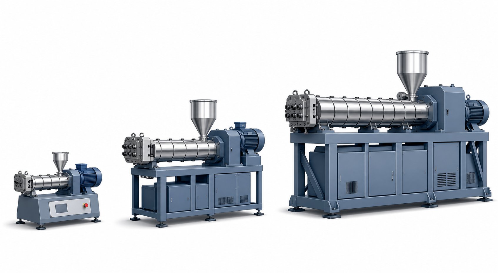
A perfectly optimized lab-scale formulation means nothing if it falls apart the moment you try to run it on a larger machine. And that scenario is far more common than most researchers expect. The physics of extrusion do not scale linearly - double the screw diameter and you do not simply get double the throughput with identical product quality. You get a fundamentally different thermal environment, altered shear conditions, and shifted residence time behavior. Understanding these non-linear relationships is what separates a smooth commercialization path from months of frustrating pilot-plant troubleshooting.
Scale-Up Principles from Lab to Production
Three foundational principles govern how laboratory extrusion data translates to larger twin screw extruders, and ignoring any one of them invites process failure at the next scale.
Geometric similarity is the starting point. When the lab extruder and the production extruder share proportional screw geometry - the same L/D ratio, the same ratio of outer diameter to inner diameter (OD/ID), and analogous screw element design philosophy - you create a framework where process parameters can be meaningfully compared across scales. As Thermo Fisher Scientific's scale-up research emphasizes, geometric similarity does not eliminate the need for parameter adjustment, but it makes parameter-based scale-up achievable. Without it, you are essentially transferring a process between two fundamentally different machines, and predicting behavior becomes exponentially harder.
Specific mechanical energy (SME) matching is the most critical process parameter to preserve. SME quantifies the mechanical work input per unit mass of material - essentially, how much energy the screws deliver into your compound. A case study published by Dow demonstrates this vividly: a masterbatch optimized on a 26 mm lab extruder at an SME of 0.083 kWh/kg was scaled to a 40 mm pilot machine. When the initial pilot run produced an SME of only 0.055 kWh/kg - roughly 34% lower - the result was phase separation, poor mixing, and material that could not even be pelletized. Only after screw design, temperature profile, and screw speed were adjusted to bring SME back to 0.079 kWh/kg did the process stabilize. The same pattern repeated at the 92 mm production scale, where initial SME dropped to a catastrophic 0.026 kWh/kg before corrective changes restored it to 0.086 kWh/kg.
Residence time distribution (RTD) alignment completes the triad. RTD defines how long material is exposed to thermal and mechanical stress. Larger extruders can exhibit different fill levels and altered residence time profiles even when running at proportionally scaled parameters. If your lab process relies on a tight, narrow RTD to ensure every particle receives uniform treatment - as pharmaceutical amorphous solid dispersions demand - a wider RTD at production scale can introduce variability in dissolution performance, melt homogeneity, or amorphous stability.
Why is direct throughput scaling not linear? Because when screw diameter increases, surface area grows with the square of the diameter while volume grows with the cube. This shifting ratio means larger machines have proportionally less barrel surface area per unit of material volume. Heat transfer control degrades dramatically as diameter rises, and thermal management strategies that worked effortlessly on a small double screw extruder may prove insufficient on a production-scale machine. Maximum throughput at the larger scale is typically estimated using either a volumetric approach (cube of the diameter ratio, for power-limited processes) or a surface-area approach (square of the diameter ratio, for heat-transfer-limited processes) - but both are starting estimates, not guarantees.
Bridging Lab Data to Pilot and Full-Scale Operations
If scale-up success hinges on preserving the material's experience across equipment sizes, you need to capture the right data during every lab-scale run. Think of your lab extruder not just as a sample-making tool but as a data-generation instrument. The quality of your scale-up prediction is only as good as the data you collect at the bench.
Four data points deserve rigorous attention during laboratory extrusion trials:
- Specific mechanical energy: Calculate SME for every experimental condition using motor power draw, screw speed, and throughput rate. This becomes your primary scale-up reference value - the number you will work to match at pilot and production scale.
- Melt temperature profiles: Record actual melt temperature at the die exit, not just barrel set-point temperatures. The difference between set temperature and actual melt temperature reveals how much viscous dissipation your screw configuration generates - information that is critical when the thermal balance shifts at larger diameters.
- Pressure drop across the die: Die pressure reflects melt viscosity, flow rate, and die geometry. Monitoring it provides an indirect but powerful indicator of melt quality and process stability.
- Torque readings at various RPMs: Torque as a function of screw speed maps the relationship between energy input and processing conditions. This relationship should remain consistent across scales when SME is properly matched.
L/D ratio consistency between your lab and target production equipment facilitates smoother transitions. When both machines share the same L/D - say, 40:1 - you can use the same relative screw element sequence, place kneading blocks and venting zones at proportionally equivalent positions along the barrel, and expect broadly similar processing behavior. The Dow case study used geometrically similar co-rotating twin screw extruders at 26 mm, 40 mm, and 92 mm - all with an L/D of 44 and an OD/ID ratio of 1.55 - precisely to enable meaningful parameter-based scale-up.
The table below highlights the practical differences between lab-scale and production-scale twin screw extruders, illustrating why both remain essential at different stages of development.
| Parameter | Lab Scale | Production Scale |
|---|---|---|
| Typical Screw Diameter | ~10-30 mm | ~60-200+ mm |
| Throughput Range | Grams to low kg/hr | Hundreds to thousands of kg/hr |
| Material per Experiment | Grams to a few kilograms | Tens to hundreds of kilograms |
| Cost per Experimental Run | Low - minimal raw material and energy | High - significant material, energy, and labor costs |
| Staffing Requirements | Single researcher | Full operations team (operators, QC, maintenance) |
| Experimental Flexibility | High - screw swaps and parameter changes within minutes | Low - configuration changes require scheduled downtime |
| Heat Transfer Control | Excellent - high surface-area-to-volume ratio | Challenging - reduced A/V ratio demands careful thermal design |
| Primary Purpose | Formulation screening, process understanding, data generation | Commercial manufacturing, continuous output, cost-optimized production |
Why Lab Scale Experiments Remain Indispensable
Some teams question whether lab-scale work is necessary at all - especially when pilot equipment is available. The cost argument alone makes a compelling case. Screening ten formulation variations on a lab machine might consume one or two kilograms of material total. Running those same ten formulations on a production-scale extruder could require hundreds of kilograms per trial, plus the labor of a full operations crew and the opportunity cost of tying up a commercial production line. For pharmaceutical applications where API costs can reach thousands of dollars per gram, the math is overwhelming.
But the value of lab-scale work extends beyond material savings. A lab scale twin screw extruder is not a miniaturized production unit - it is a precision research instrument designed for data generation and process understanding. The high surface-area-to-volume ratio that complicates direct scale-up is actually an advantage during development because it provides excellent thermal control. The small batch sizes that seem limiting are actually liberating because they let you fail fast, learn quickly, and iterate without financial pain. And the SME, RTD, melt temperature, and pressure data you capture at the bench become the quantitative foundation that makes every subsequent scale-up decision defensible rather than speculative.
Consider the Dow masterbatch example one more time. The 26 mm lab extruder identified the optimal SME of 0.083 kWh/kg. That single number became the reference point that guided every troubleshooting decision at both the 40 mm and 92 mm scales. Without it, the team would have been adjusting screw designs, temperature profiles, and feed configurations with no quantitative anchor - essentially guessing. With it, they could diagnose each problem (SME too low), identify the root cause (insufficient energy transfer due to lubrication effects or altered thermal dynamics), and implement targeted fixes that brought the process back to proven territory.
That is the real role of laboratory extrusion in any development program: it generates the process knowledge that de-risks everything downstream. The formulations you optimize and the data you collect at the bench are your insurance policy against expensive surprises at scale. Yet even the most carefully generated lab data can be undermined by operational mistakes that compromise data quality before scale-up ever begins - and those pitfalls deserve their own focused discussion.
Common Mistakes and Troubleshooting Lab Scale Extruder Issues
Every researcher who has spent time behind a lab scale twin screw extruder has a story about a run that went sideways - inconsistent strands, a torque alarm that killed a promising experiment, or an extrudate riddled with bubbles that should not have been there. The frustrating part? Most of these failures are preventable. They stem from a handful of recurring operational mistakes that, once you recognize them, become straightforward to avoid. The problem is that troubleshooting guidance written for production-scale equipment does not translate cleanly to lab-scale work, where smaller dimensions amplify certain errors and create entirely new ones that larger machines never encounter.
Feeding and Throughput Problems
If your extruder system is producing inconsistent output, the root cause is almost always upstream of the screws - in the feeding section. At production scale, feed-related issues are a nuisance. At lab scale, they can render your data meaningless.
Bridging in hoppers is the most common culprit. Imagine a fine pharmaceutical powder or a low-bulk-density additive forming an arch inside your small-diameter hopper, suspending itself above the feed throat while the screws below spin empty. The extruder feed barrel receives material in erratic clumps instead of a steady stream, and every downstream measurement - torque, melt pressure, die output - oscillates in response. On production equipment with large hoppers, mechanical agitators or vibration systems keep material flowing. On a benchtop unit with a compact hopper, bridging can occur with startling frequency, especially with cohesive powders, electrostatic-prone granules, or fibrous additives with irregular particle shapes.
The fix starts with understanding what causes the bridge. High humidity makes particles sticky and prone to clumping. Irregular particle geometry lets materials interlock into stable arches. And an oversized or poorly shaped hopper transition - where the hopper narrows toward the feed throat - creates the geometric conditions for arch formation. Practical solutions include installing a small vibratory device on the hopper wall, using anti-bridging inserts that break arch formation continuously, and storing raw materials in dry, climate-controlled environments to prevent moisture-induced clumping before feeding even begins.
Flood feeding versus starve feeding mistakes trip up researchers who are new to twin screw operation. In a flood-fed configuration, the hopper gravity-feeds material directly into the screws, and the screw speed determines throughput. In starve-fed operation - the standard mode for most twin screw work - a separate feeder meters material at a controlled rate, and the screws run partially filled. Starve feeding gives you independent control over throughput and screw speed, which is essential for decoupling mixing intensity from feed rate. The mistake happens when researchers inadvertently flood-feed their extruder by setting the feeder output too high, overfilling the screw channels. The result is torque spikes, inconsistent residence time, and a loss of the independent process control that makes twin screw extrusion so valuable for research.
Feeder calibration at low throughputs deserves special attention because it is a challenge unique to lab-scale work. At production rates of 50 or 100 kg/hr, a gravimetric feeder delivers smooth, accurate flow. At lab-scale rates of 200 grams per hour or less, the same feeder technology struggles - small fluctuations that are proportionally insignificant at high throughput become major percentage swings at low rates. Recalibrating with the actual material you plan to process, rather than a substitute, is critical. Volumetric feeders are simpler but less accurate; gravimetric feeders offer better control but require clean, properly zeroed load cells to function at their best in these low-rate regimes.
One often overlooked contributor to feeding problems is the screw element choice directly beneath the feed throat. If you place tight-pitch conveying elements or, worse, kneading blocks in the feed zone, incoming material has nowhere to go. The screws cannot accept material fast enough, feed-throat pressure builds, and material backs up into the hopper. The solution is always the same: use large-pitch conveying elements in the feed section to maximize the open volume available for material intake. This ensures a smooth handoff from feeder to screw channel, regardless of your material's flow characteristics.
Temperature, Degradation, and Die Swell Issues
Temperature management on a lab-scale extruder is simultaneously easier and harder than on a production machine. Easier because the high surface-area-to-volume ratio of a small barrel gives heating and cooling systems excellent leverage over melt temperature. Harder because that same ratio means small errors in temperature setpoints produce outsized effects on the material. Set a barrel zone 15 degrees too high on a 90 mm production extruder and the thermal mass of the melt may buffer the error. Set it 15 degrees too high on a 16 mm lab extruder and you can push your polymer past its degradation threshold in seconds.
Thermal degradation from incorrect temperature profiling manifests as discoloration, loss of molecular weight, bubble formation, and deteriorated mechanical properties in your extrudate. The telltale sign is a brown or yellow tint in a material that should be clear or white. Common causes include setting the mixing zone too hot (relying on barrel heat for melting instead of letting shear energy from kneading blocks do part of the work), failing to ramp temperatures gradually from the feed zone forward, or neglecting to activate barrel cooling in high-shear zones where viscous dissipation generates significant heat. For heat-sensitive materials like PVC or biodegradable polyesters, adjusting the temperature profile to match the specific polymer's processing window is not optional - it is the difference between usable data and wasted material.
Surging caused by inadequate back-pressure shows up as rhythmic pulsation in your extrudate strand - thicker, then thinner, then thicker again. This oscillation means the melt is not being delivered to the die at a constant rate. On lab-scale equipment, surging often traces back to insufficient back-pressure in the metering zone. Without enough restriction ahead of the die, the screws pump material in irregular bursts rather than a steady flow. Adding a reverse conveying element or a neutral kneading block before the discharge zone creates the back-pressure needed to stabilize flow. Die geometry also plays a role - a die with too large an opening provides too little restriction, amplifying any upstream flow inconsistency.
Die swell management becomes a concern when the extrudate expands noticeably after exiting the die, distorting the intended cross-sectional geometry. Die swell results from the elastic recovery of polymer chains that were stretched and oriented while flowing through the die land. At lab scale, where die dimensions are small, even modest die swell can significantly alter your sample geometry. Managing it requires attention to die land length (longer lands allow more chain relaxation before exit), melt temperature (higher temperatures reduce elasticity but risk degradation), and extrusion rate (slower rates reduce shear history and the resulting elastic memory).
Proper venting is the quiet hero of clean extrudate. Moisture trapped in hygroscopic resins or volatiles released during reactive extrusion must escape the barrel before reaching the die, or they create bubbles, surface roughness, and internal voids that compromise your samples. Lab-scale extruders typically offer one or two vent port locations along the barrel. Ensuring these ports are open, that the upstream melt seal (created by a reverse element or reverse kneading block) is functioning correctly, and that vacuum assist is applied when processing high-moisture materials can eliminate an entire category of defects that would otherwise contaminate your experimental results.
Avoiding Screw Design Mistakes in Lab Experiments
Of all the operational errors that plague lab-scale extrusion, one stands above the rest in both frequency and consequence: using a single, generic screw configuration for every material and every application. It is the extruder equivalent of using the same recipe for bread and for cake - technically you are baking in both cases, but the results will disappoint.
Different polymers and formulations impose different demands on the screw profile. A high-viscosity engineering thermoplastic loaded with glass fiber needs aggressive kneading blocks to break filler agglomerates and enough torque headroom to handle the mechanical resistance. A shear-sensitive pharmaceutical blend with an active ingredient that degrades above 160 degrees Celsius needs gentle distributive mixing elements with minimal energy input. Running either material through a screw configuration designed for the other produces poor mixing in one case and degradation in the other - and both generate misleading data that will not translate at scale.
Here are the most common and consequential screw design pitfalls researchers encounter:
- Incorrect kneading block intensity for the material: Overly aggressive kneading blocks (narrow discs, high stagger angles) generate excessive shear and temperature rise for heat-sensitive polymers, causing degradation. Conversely, overly gentle blocks fail to achieve adequate dispersion for filled or immiscible blends, producing inhomogeneous extrudate that yields inconsistent test results.
- Insufficient or excessive back-pressure elements: Too few reverse elements or neutral kneading blocks result in low fill levels and erratic flow. Too many choke the barrel, spike torque, and can cause material backup into the vent ports or feed throat.
- Inadequate venting: Omitting a proper melt seal upstream of the vent port allows polymer to escape through the vent instead of volatiles. Placing the vent in a high-pressure zone rather than a low-fill conveying section defeats the purpose entirely.
- Wrong barrel temperature profile: A flat temperature profile across all zones ignores the reality that different barrel sections serve different functions. The feed zone needs lower temperatures to prevent premature melting and bridging, mixing zones need enough heat to maintain processable viscosity, and the metering zone may need cooling to stabilize melt properties before the die.
- Neglecting die design: The die is not an afterthought. A die with incorrect land length, an oversized opening that provides no back-pressure, or a poor surface finish that induces melt fracture at the wall will undermine even a perfectly optimized screw and barrel configuration.
The challenge for many R&D teams - especially university labs and small research groups - is that screw design expertise is not something you pick up from a manual. It requires understanding the interplay between element geometry, material rheology, and process objectives at a level that takes years of hands-on experience to develop. Teams that lack in-house screw design engineering often default to the factory-standard configuration that shipped with their equipment, adjusting barrel temperatures and screw speed endlessly when the real solution is a different arrangement of elements on the shaft.
This is where specialized support services become genuinely valuable. NANHAIYA's Custom Screw Design Services, for example, provide R&D teams and university labs with expert screw and barrel design consultation tailored to specific materials and experimental goals. Rather than spending weeks on trial-and-error with generic configurations, a team processing a novel biopolymer or a challenging pharmaceutical formulation can get a screw layout designed for their exact material and objectives - eliminating the most consequential variable from their troubleshooting list before the first experiment even begins.
Operational mistakes erode data quality. Screw design mistakes erode the entire experimental foundation. Addressing both is essential, but even a flawlessly operated and configured lab extruder only delivers its full value when you choose the right machine in the first place - and that selection process involves its own set of criteria that deserve careful evaluation.
How to Select the Right Lab Scale Twin Screw Extruder
Knowing how to operate a lab scale twin screw extruder and troubleshoot its quirks is valuable - but only if you are standing in front of the right machine in the first place. The selection process itself is where many researchers stumble, overwhelmed by spec sheets from multiple twin screw extruder manufacturers, uncertain which parameters actually matter for their work, and tempted to make decisions based on twin screw extruder price alone. A more systematic approach pays dividends for years.
Evaluation Criteria for Comparing Lab Extruder Options
When you browse a twin screw extruder for sale listing or request quotes from vendors, every machine looks impressive on paper. The challenge is knowing which specifications align with your actual research needs and which are marketing padding. The table below organizes the criteria that genuinely differentiate one laboratory scale extruder from another - ranked by their practical impact on experimental flexibility and long-term value.
| Evaluation Criterion | What to Look For | Why It Matters |
|---|---|---|
| Custom Screw Design Availability | Vendor offers bespoke screw element design and consultation for specific materials and processes | Lab work frequently involves novel materials that demand non-standard element sequences; without custom options, you are locked into generic configurations that limit experimental depth |
| Screw Diameter Range | Options spanning the range your throughput and batch size requirements demand | Determines minimum material consumption per run and maximum achievable throughput |
| Available L/D Ratios | Multiple L/D options (e.g., 32:1, 40:1, 48:1) or modular barrel extension capability | Longer L/D accommodates complex multi-zone processes; shorter L/D suits simpler formulations and heat-sensitive materials |
| Torque Capacity | Sufficient torque for the highest-viscosity materials you plan to process | Inadequate torque causes motor overloads and restricts your formulation range - especially with heavily filled compounds |
| Maximum RPM | Wide speed range with stable low-end operation | Enables shear rate control from gentle distributive mixing to aggressive dispersive processing |
| Modular Barrel Flexibility | Segmented barrel design with interchangeable sections for venting, side feeding, and liquid injection | Allows process reconfiguration without purchasing entirely new equipment |
| Ease of Disassembly and Cleaning | Quick-open barrel mechanism and tool-free screw removal | Reduces downtime between formulation changes - critical when running multiple experiments per day |
| Available Die Options | Multiple die geometries (strand, film, sheet, profile) with quick-change capability | Different sample types require different die configurations; limited die options restrict the characterization methods you can employ |
| Data Acquisition Capability | Real-time logging of torque, melt temperature, pressure, and screw speed with export functionality | Scale-up depends on quantitative process data; machines without robust data capture generate samples but not the information needed to transfer processes to larger equipment |
| Vendor Support for Custom Configurations | Responsive technical support, application engineering assistance, and willingness to develop non-standard solutions | Lab-scale research evolves - your needs in two years will differ from today, and a vendor who can adapt with you protects your investment |
Notice that custom screw design availability sits at the top of the list - not by accident. Every other specification defines what the machine can theoretically do. Custom screw design determines what it actually delivers with your specific material, in your specific process, for your specific research goals.
Why Custom Screw and Barrel Design Support Matters
Here is a distinction that catches many first-time buyers off guard. When purchasing production-scale equipment, standard screw configurations often perform adequately because the materials being processed are well-characterized and the process conditions are established. Lab-scale work is the opposite. You are frequently processing novel materials, exploring unconventional conditions, and pushing formulations into territory where no standard configuration has been optimized. A twin-screw extruder machine purchased with a factory-default screw layout may handle your first application reasonably well - but the moment your research direction shifts, that generic setup becomes a constraint rather than a tool.
Custom screw and barrel design support becomes essential in scenarios where standard configurations simply cannot deliver the precision your experiments demand:
- Processing novel biopolymers: Materials like PHA blends or starch-based composites have narrow processing windows and unusual rheological behavior that require tailored element sequences to avoid degradation while achieving adequate mixing.
- Pharmaceutical hot-melt applications with active ingredient sensitivity: APIs that degrade above specific shear or temperature thresholds need screw designs that deliver sufficient mixing energy without crossing those limits - a balance that generic configurations rarely achieve.
- Reactive extrusion requiring precise residence time control: Grafting, crosslinking, and chain extension reactions depend on material spending exactly the right amount of time in high-shear zones. Custom element arrangements with calculated reverse-element placement and kneading block sequencing are essential.
- Processing materials with unusual rheological behavior: Shear-thinning, shear-thickening, or yield-stress fluids respond unpredictably to standard screw geometries, often requiring bespoke element designs to achieve stable conveying and uniform mixing.
For R&D labs, pilot-line operators, universities, and small-batch processing teams, maintaining full-time screw design engineering staff is rarely practical or cost-effective. This is precisely where external expertise fills a critical gap. NANHAIYA's Custom Screw Design Services provide tailored screw and barrel design for specialized materials and compact equipment - giving research teams access to application-specific design consultation without the overhead of an in-house engineering department. The practical benefit is significant: instead of cycling through generic configurations and hoping one works, you start with a design matched to your material and objectives, compressing the time from equipment setup to publishable data.
Making a Confident Selection Decision
With evaluation criteria defined and the importance of custom design support established, the final step is a decision-making framework you can apply regardless of which twin-screw extruder manufacturer you are evaluating. Four principles, followed in sequence, consistently lead to a well-matched purchase:
Define your primary application first. Are you mainly compounding filled thermoplastics? Screening pharmaceutical hot-melt dispersions? Developing biodegradable blends? Your dominant application dictates whether you prioritize torque capacity, temperature control precision, or gentle mixing capability. Trying to find a machine that excels at everything usually means settling for one that excels at nothing.
Match specifications to your material requirements. List the highest-viscosity material you expect to process, the most temperature-sensitive formulation in your research plan, and the smallest batch size you need to run meaningfully. Cross-reference these against the torque, temperature zoning, and screw diameter options on your shortlist. Any machine that cannot handle your most demanding material is a machine you will outgrow.
Prioritize modularity and vendor support. Research directions change. A laboratory scale extruder with a modular barrel, interchangeable screw elements, and a responsive vendor who offers application engineering assistance adapts with you. A rigid, fixed-configuration machine becomes obsolete the moment your research pivots - and in a lab environment, pivots are inevitable.
Verify that custom screw element options are available for future experimental flexibility. This is the criterion most often skipped during purchasing and most often regretted afterward. Ask your vendor directly: can you supply custom-designed kneading blocks, mixing elements, and conveying elements tailored to specific materials? If the answer is no - or if lead times stretch into months - factor that limitation into your decision. Your first project may use a standard configuration, but your third or fourth almost certainly will not.
Selecting a lab scale twin screw extruder is not about finding the cheapest option or the most feature-laden spec sheet. It is about matching a precision research instrument to the work you need it to do - today and in the experiments you have not yet imagined. Get the evaluation criteria right, secure access to custom design support, and you build a foundation that turns every gram of material and every hour of run time into data you can trust, scale, and defend.
Frequently Asked Questions About Lab Scale Twin Screw Extruders
1. What is the typical screw diameter range for a lab scale twin screw extruder?
Lab scale twin screw extruders generally feature screw diameters between 10 mm and 30 mm. Smaller diameters (10-16 mm) allow experiments with as little as a few hundred grams of raw material, making them ideal for expensive APIs or scarce novel polymers. Larger lab-scale diameters (20-30 mm) offer higher throughput and can serve as a bridge toward pilot-scale trials, though they require proportionally more material per run. The screw diameter you choose directly determines your minimum batch size, free volume inside the barrel, and the overall throughput ceiling of every experiment.
2. What is the difference between co-rotating and counter-rotating twin screw extruders?
Co-rotating twin screw extruders have both screws turning in the same direction, generating high shear and excellent distributive and dispersive mixing through active channel-to-channel material transfer. They are self-wiping, which prevents material stagnation and thermal degradation - making them the dominant choice for polymer compounding, reactive extrusion, and pharmaceutical hot-melt extrusion. Counter-rotating extruders turn screws in opposite directions, producing lower shear with a calender-like flow and higher localized pressure generation. They suit shear-sensitive materials like PVC dry blends and profile extrusion trials. For most R&D applications, co-rotating configurations cover the broadest experimental range.
3. How do you scale up from a lab scale twin screw extruder to production?
Successful scale-up relies on three core principles: geometric similarity (maintaining proportional screw geometry and L/D ratios across scales), specific mechanical energy (SME) matching (ensuring equivalent energy input per unit mass), and residence time distribution alignment. Researchers should capture SME values, actual melt temperatures at the die, pressure drop data, and torque readings at various RPMs during lab runs. These quantitative benchmarks serve as reference targets when adjusting screw design, temperature profiles, and feed rates on larger equipment. Direct throughput scaling is not linear because heat transfer behavior changes as the surface-area-to-volume ratio shifts with increasing screw diameter.
4. Why is modular screw design important for lab scale extrusion research?
Modular screw design allows researchers to swap individual elements - conveying segments, kneading blocks, distributive mixing elements, and reverse elements - along a common splined shaft. This means you can fundamentally change how the machine processes material in minutes rather than days. Different experiments demand different configurations: polymer compounding needs aggressive kneading sections for filler dispersion, pharmaceutical hot-melt extrusion requires gentler mixing to protect active ingredients, and reactive extrusion demands extended residence time zones. Custom screw design services, such as those offered by NANHAIYA (nhyscrews.com), can help teams optimize element arrangements for specific materials and goals without costly trial-and-error.
5. What are the most common mistakes when operating a lab scale twin screw extruder?
The most frequent and damaging mistakes include using a single generic screw configuration for every material, incorrect kneading block intensity that causes degradation or poor dispersion, hopper bridging from cohesive powders, improper starve-fed versus flood-fed operation, and setting flat barrel temperature profiles that ignore the different functional requirements of each zone. Feeding issues at low throughputs are especially problematic at lab scale because small fluctuations in feed rate create proportionally large process variations. Neglecting die design and omitting proper venting for moisture removal are also common oversights that compromise extrudate quality and data reliability.
Written by
Nanhaiya Technical Team
Zhoushan Nanhaiya Plastic Machinery Co., Ltd.
The Nanhaiya technical team supports screw and barrel manufacturing projects through application review, technical communication, custom manufacturing coordination, and production and quality control.
Discuss Your Application
Related Articles
More insights on screw barrel technology and plastics processing.
WPC Profile Extrusion Machine Decoded: Raw Blend To Flawless Profile
Oct 15, 2026
Learn how a WPC profile extrusion machine works — from extruder types and temperature zones to troubleshooting, wear management, and emerging co-extrusion trends.
Read Article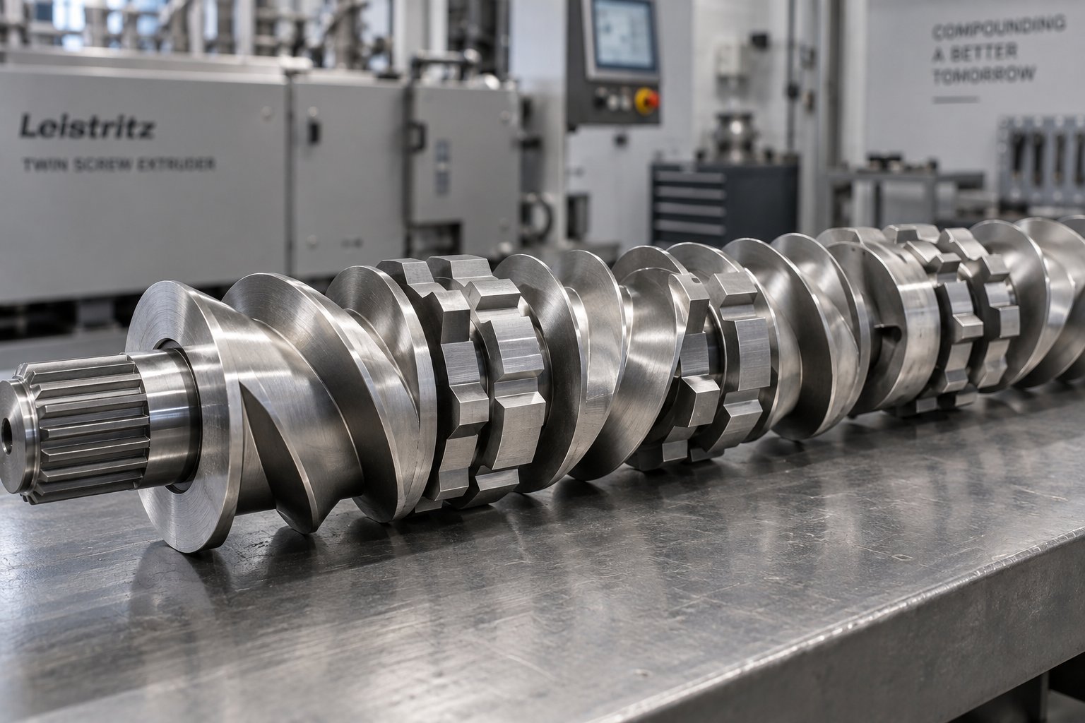
Twin Screw Extruder Screw Decoded: Geometry, Wear & Profile Fixes
Oct 14, 2026
Master twin screw extruder screw design: geometry parameters, kneading block stagger angles, element classification, wear mechanisms, and profile troubleshooting fixes.
Read Article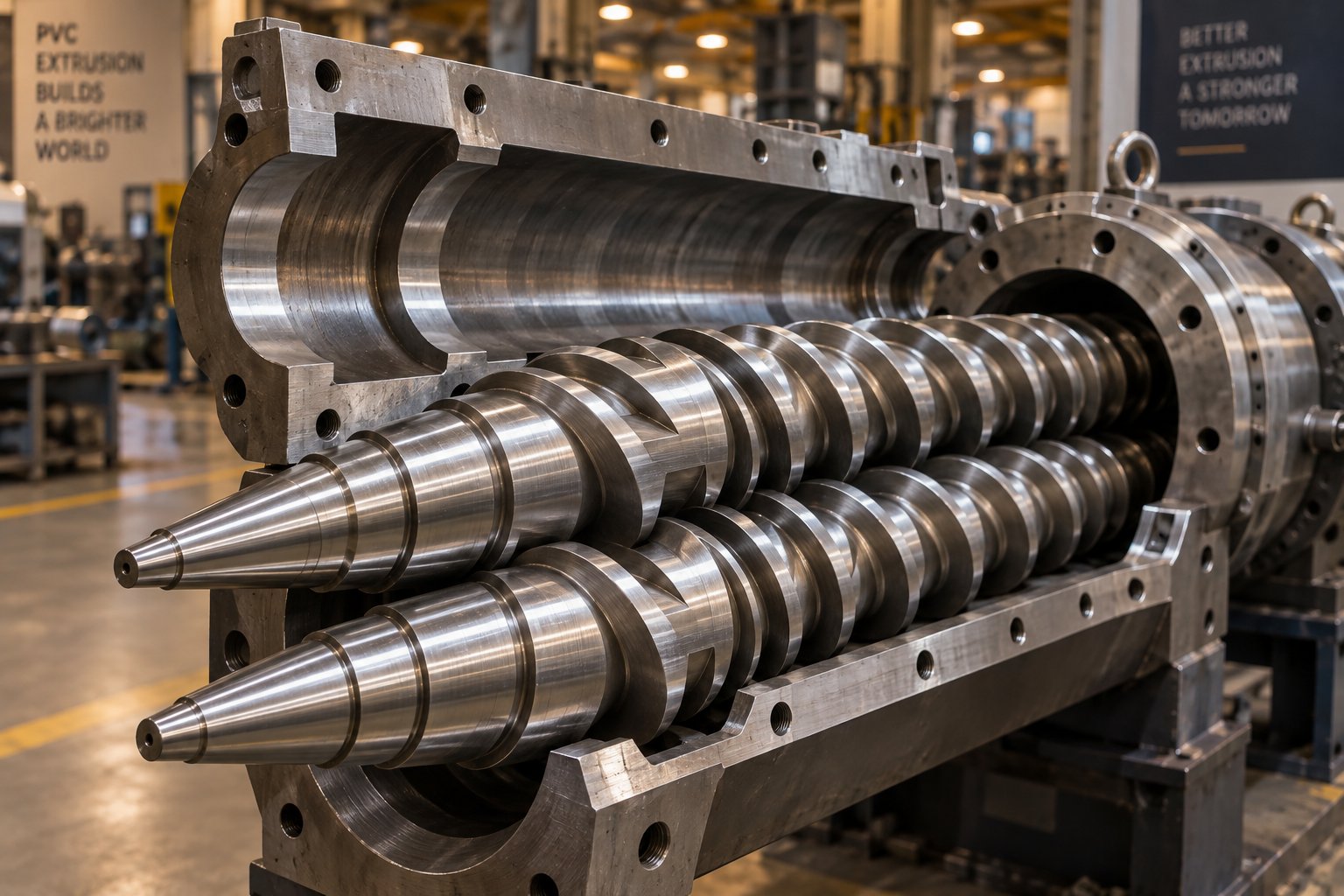
Your Extruder Screw Barrel For PVC Is Burning Resin — Here's Why
Oct 14, 2026
PVC burns resin when screw barrel geometry, metallurgy, or temperature zoning is wrong. Learn the exact specs, alloys, and wear fixes for PVC extrusion.
Read ArticleLooking for something else?
Search by material, symptom or product and jump straight to the relevant page.
These are navigation suggestions based on keyword matching — not a quotation, not a delivery commitment, and not a substitute for engineering review. Final specification is confirmed by our engineers against your drawings and processed material.
Need help with screw barrel selection?
Share your machine model, processed material and application. Our team can help with pricing and technical support.