

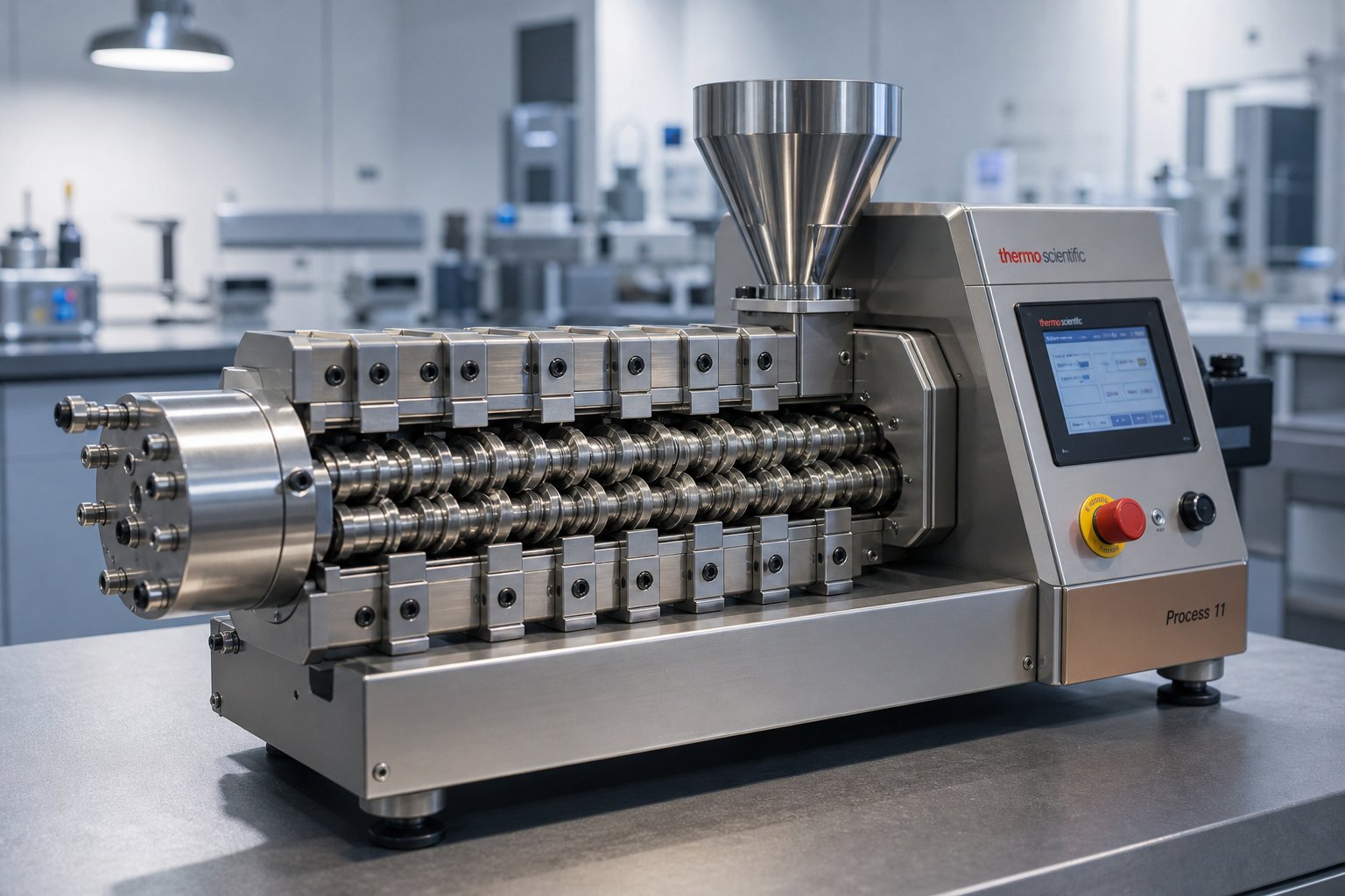
What Is a Lab Co-Rotating Twin Screw Extruder
Imagine you have a promising new polymer blend, a novel bioplastic formulation, or an experimental drug compound, but only a handful of grams to work with. Running a full production line is out of the question. A benchtop mixer won't replicate real-world extrusion conditions. This is exactly the gap a lab co-rotation twin screw extruder fills.
Defining the Lab Co-Rotating Twin Screw Extruder
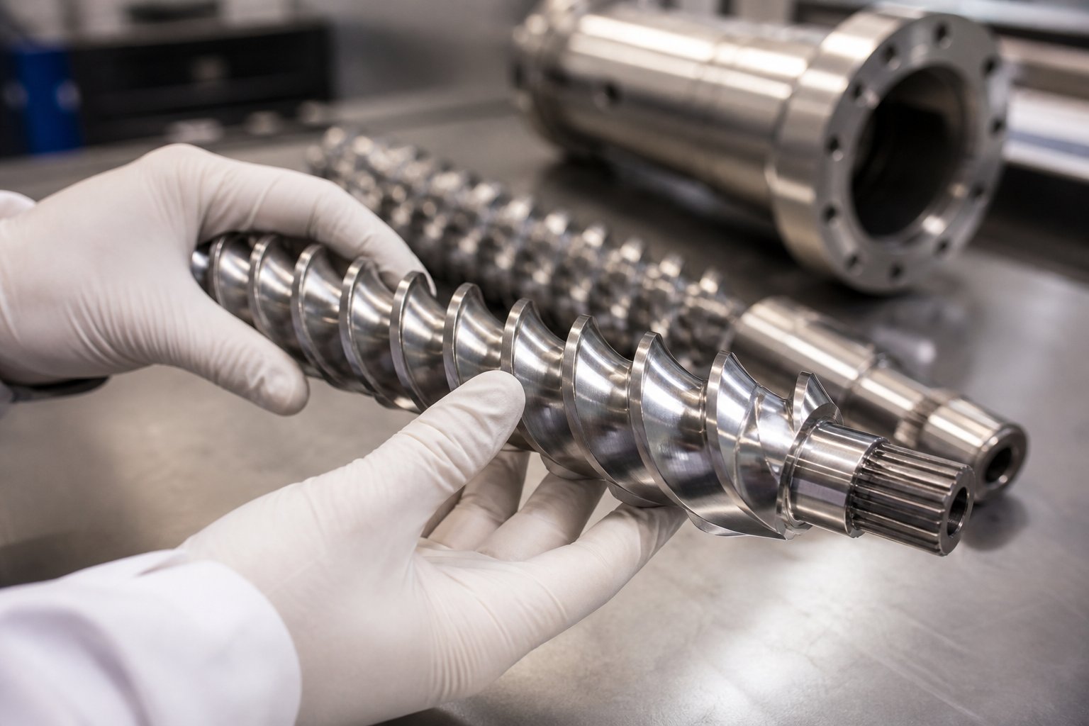
A lab co-rotating twin screw extruder is a compact, modular extrusion system in which two intermeshing screws rotate in the same direction inside a heated barrel, engineered specifically for research, development, and small-batch material processing.
Three technical terms show up repeatedly in catalogs and spec sheets, and understanding how they connect saves a lot of confusion. "Co-rotating" means both screws turn in the same direction, producing a figure-eight material flow path and a self-wiping action that keeps the barrel clean. "Parallel" describes the screw geometry: both screws share a constant diameter along their entire length, distinguishing them from conical designs. "Intermeshing" refers to the way the screw flights overlap, which forces material through tight clearances for thorough mixing. Put them together and you get a parallel twin screw extruder with co-rotating, intermeshing screws, the configuration most widely used in R&D environments.
What separates a lab-scale machine from its industrial counterpart is scale and intent. Production extruders commonly feature screw diameters of 40 mm and above, optimized for high throughput. A lab-scale double screw extruder machine, by contrast, typically operates with screw diameters in the 12 to 26 mm range and processes material at rates measured in grams or low kilograms per hour. The priority shifts from volume to flexibility: rapid screw changes, precise temperature control across multiple barrel zones, and the ability to run experiments with minimal material waste.
Who Uses Lab-Scale Co-Rotating Extruders
The user base for these machines is broader than most people expect. University polymer labs rely on them for fundamental studies of melt behavior and blend morphology. Pharmaceutical R&D teams use them to develop hot-melt extrusion formulations where precise shear and temperature control protect expensive active ingredients. Food science researchers explore textured proteins and starch-based products. Pilot-line operators validate formulations before committing to production-scale trials. Materials scientists working on nanocomposites, bioplastics, and advanced fiber composites depend on the co rotating twin screw extruder platform for its unmatched mixing capability at small volumes.
In every case, the lab extruder serves a critical role: it bridges the gap between benchtop mixing, where conditions rarely mirror real extrusion, and full production, where trial-and-error is prohibitively expensive. The data generated at lab scale, including torque curves, melt temperatures, and specific energy inputs, becomes the foundation for every decision that follows.
Yet the real power of these machines lies not just in their size or user base, but in how material actually moves through them, zone by zone, from hopper to die.
How Co-Rotating Twin Screw Extrusion Works Step by Step
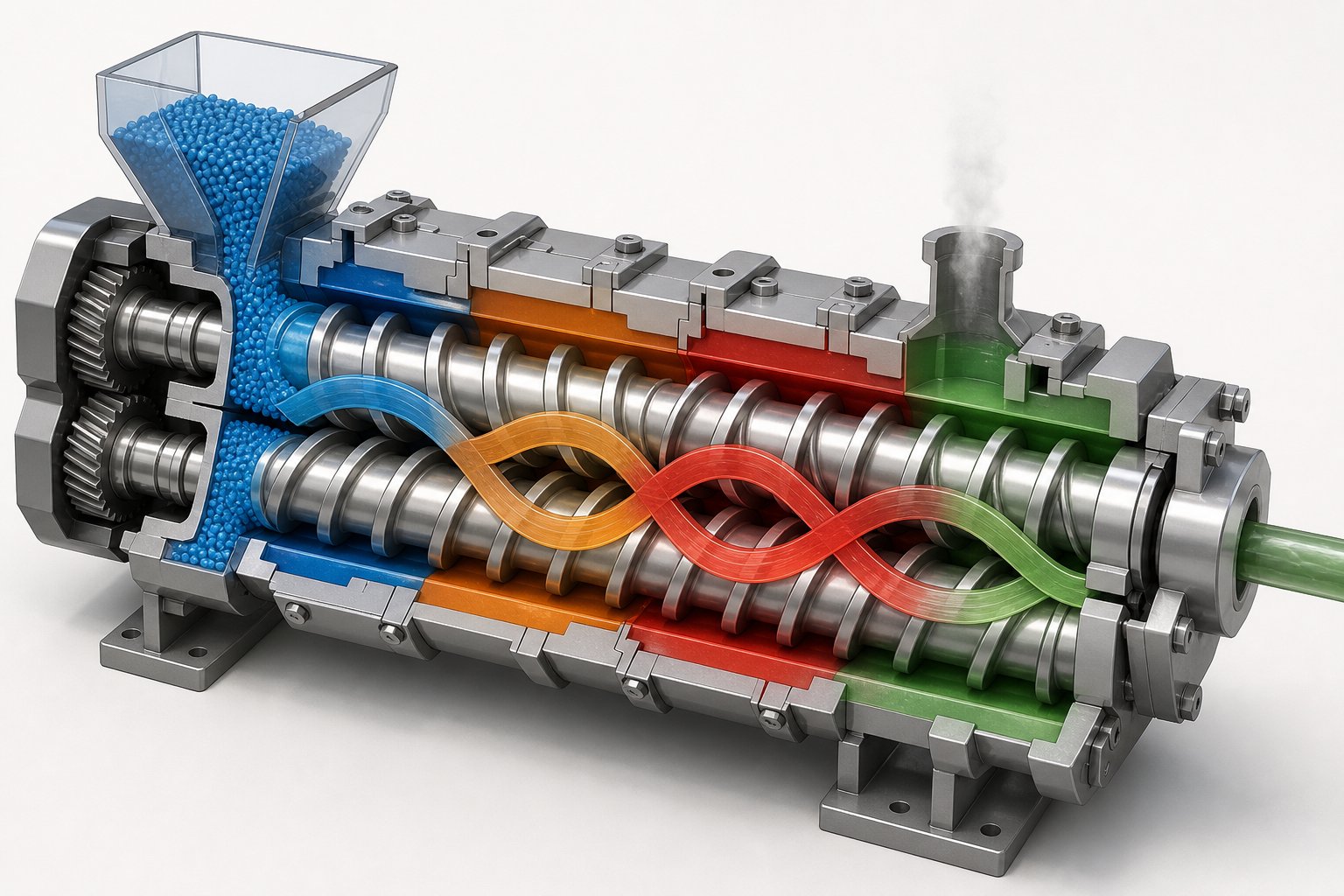
Catalogs list barrel zones, torque ratings, and throughput numbers, but they rarely walk you through what actually happens to your material once it drops into the feed throat. For researchers running precious, often irreplaceable samples, that gap in understanding can mean the difference between a successful experiment and a wasted batch. Here is a zone-by-zone look at how a lab co-rotating twin screw extruder processes material, with the practical nuances that matter most at small scale.
Material Conveying and Feeding Zone
Everything starts at the feeder. In production-scale twin-screw extruders, feeding thousands of kilograms per hour is routine. At lab scale, you might need to deliver as little as 100 grams per hour with consistent accuracy. That is an entirely different engineering challenge.
Lab machines predominantly use starve-feeding, where the feeder meters material into the barrel at a controlled rate rather than letting gravity flood the feed opening. Why does this matter? In starve-fed operation, the screw speed and feed rate are decoupled. You set the screw RPM independently of how much material enters the machine, giving you direct control over shear, residence time, and fill level. This is the standard operating mode for co-rotating twin-screw extruders used in compounding research, and it is essential for reproducing experimental conditions run after run.
Flood-feeding, where the hopper is kept full and the screws pull material in at their natural conveyance rate, is more common in single-screw systems. In a lab co-rotating setup, flood-feeding limits your ability to fine-tune processing parameters and can cause erratic torque spikes with small batches.
The practical headache at lab scale is feeder precision. Gravimetric feeders, which continuously weigh material on a loss-in-weight basis, offer the best accuracy for gram-level dosing. Volumetric feeders are simpler and cheaper but less precise, especially with powders that tend to bridge, rat-hole, or fluctuate in bulk density. Feeding specialists emphasize that understanding your ingredient's flow properties, including particle size, cohesion, and moisture content, is critical before selecting a feeder type. For labs working with experimental fillers or irregularly shaped additives, even small inconsistencies at the feed throat cascade into large variability at the die.
Melting, Mixing, and Devolatilization Zones
Once material enters the barrel, the co-rotating screw geometry takes over. Picture two screws turning in the same direction with their flights overlapping. As one screw's flight enters the channel of the other, material is swept forward in C-shaped pockets. This positive displacement mechanism means the machine pushes material forward mechanically rather than relying on friction alone, making it far more reliable for sticky, low-friction, or powdery feeds that a single screw would struggle to convey.
The melting zone is where solid pellets, powders, or granules transition into a molten state. Heat comes from two sources simultaneously: the electrically heated barrel zones and the mechanical shear generated by the screws. In a lab context, where sample volumes are small, the barrel heaters do proportionally more of the work. Kneading block elements positioned in this zone intensify shear, accelerating melting without requiring excessive barrel temperatures that could degrade sensitive materials.
Downstream of the melt zone, mixing sections handle the core job of any twin screw compounding extruder: blending polymers, dispersing fillers, and distributing additives uniformly. Two types of mixing occur here. Dispersive mixing breaks apart agglomerates, like clumps of pigment or nano-filler particles, by forcing them through tight clearances under high stress. Distributive mixing spreads those broken-down particles evenly throughout the melt. The beauty of the co-rotating design is its self-wiping action: the flank of one screw continuously scrapes material off the root of the other. This prevents dead zones where material could stagnate, overheat, and degrade, a property that is especially valuable for researchers who frequently switch between materials and cannot afford cross-contamination.
Devolatilization occurs when the screw profile creates a partially filled, low-pressure zone aligned with a vent port in the barrel. Applying vacuum at this opening draws out moisture, trapped air, residual solvents, or reaction byproducts. The screws continuously renew the melt surface exposed to vacuum, dramatically improving mass transfer efficiency. As devolatilization experts note, the zone must be properly sealed by pressure-generating elements both upstream and downstream to prevent the vacuum from disrupting adjacent barrel sections. At lab scale, even trace moisture can ruin a small experimental batch, so effective venting is not optional; it is foundational.
Die Exit and Downstream Processing
At the end of the barrel, the fully compounded melt is forced through a die that shapes it for downstream collection. What happens next depends on the experiment's goals. Strand pelletizing, where the melt exits as thin strands, is cooled in a water bath, and chopped into pellets, is the most common setup for a plastic twin screw extruder in a lab. Film casting dies produce thin films for optical or mechanical testing. Some researchers skip traditional downstream equipment entirely, collecting the melt directly for rheological analysis or microscopy.
One of the underappreciated advantages of lab-scale machines is how quickly you can swap dies. Changing from a strand die to a flat film die or a small profile die often takes minutes, not hours. This flexibility lets a single extruder serve multiple experimental objectives in a single day, something that would be impractical on a production line optimized for continuous output.
For a clear mental map, here are the key functional zones material passes through in sequence:
- Feeding zone — controlled material intake via gravimetric or volumetric feeder
- Conveying zone — forward transport by intermeshing screw flights
- Melting zone — solid-to-melt transition through barrel heat and screw shear
- Mixing zone — dispersive and distributive blending of polymers, fillers, and additives
- Devolatilization zone — vacuum-assisted removal of moisture, gases, or volatiles
- Pressure buildup zone — melt compression to generate stable flow toward the die
- Die zone — shaping the melt for downstream pelletizing, film casting, or direct analysis
Each of these zones is defined not by fixed barrel segments but by the screw elements installed along the shaft. Swap a conveying element for a kneading block and you transform a transport section into a high-shear mixing region. This modularity is what makes the co-rotating platform so powerful for research, and it raises an important question: how do you actually read a spec sheet to understand what a given machine can do?
Lab Extruder Specification Decoder for Researchers
Spec sheets from manufacturers like Coperion, Berstorff, or CPM Century Extrusion pack dense columns of numbers into tidy tables. Screw diameter, L/D ratio, torque density, barrel zone count — they all look important, but which ones actually determine whether a machine fits your experiment? Think of this section as a translator between catalog language and lab reality.
Screw Diameter and L/D Ratio Explained
Screw diameter is the single number that anchors every other specification. In a lab co-rotating twin screw extruder, diameters typically fall between 12 mm and 26 mm. A smaller diameter, say 16 mm, lets you run meaningful trials with as little as 50 to 100 grams of material. A 26 mm machine handles larger batches and bridges the gap toward pilot-scale validation. In practical terms, diameter sets the floor on how much material you need per run and the ceiling on how much throughput the machine can deliver.
L/D ratio — the screw's working length divided by its diameter — tells you how many processing stages you can fit along that length. A short ratio like 20:1 provides room for basic conveying, melting, and mixing. Stretch that to 40:1 and you gain enough barrel real estate for additional kneading sections, multiple feed ports, and one or more devolatilization zones. Industry data confirms that twin screw extruders commonly span L/D ratios from 20:1 to 48:1, with lab-scale machines most often configured between 20:1 and 40:1. Higher L/D ratios also increase residence time, which benefits reactive extrusion and thorough devolatilization but risks thermal degradation of heat-sensitive materials. Choosing the right ratio is ultimately about matching barrel length to the number of processing tasks your experiment demands.
Torque, RPM, and Barrel Zone Specifications
Torque density is a specification that confuses many first-time buyers. It represents the rotational force available per unit of screw cross-sectional area, and it determines whether the machine can process high-viscosity melts, heavily filled compounds, or stiff engineering polymers without stalling. A lab extruder with inadequate torque will hit its limit precisely when you need it most — during demanding formulations that push the motor to its maximum load.
RPM range controls shear rate. Higher screw speeds generate more shear energy, which intensifies mixing but also raises melt temperature through viscous dissipation. Most lab machines offer ranges from roughly 50 to 600 RPM, giving researchers the flexibility to dial in gentle blending for heat-sensitive biopolymers or aggressive mixing for nanocomposite dispersion.
Barrel zone count refers to how many independently heated and cooled segments line the barrel. More zones mean finer thermal resolution along the screw length. A four-zone barrel provides basic control; six to ten zones allow precise temperature profiling for complex experiments involving multiple processing stages.
| Specification | Typical Lab-Scale Range | Why It Matters |
|---|---|---|
| Screw Diameter | 12 – 26 mm | Sets minimum sample size and maximum throughput capacity |
| L/D Ratio | 20:1 to 40:1 | Determines available processing zones, residence time, and mixing intensity |
| Torque Density | Varies by manufacturer; check Nm/cm3 | Governs ability to process high-viscosity or heavily filled materials without motor stall |
| Screw Speed (RPM) | 50 – 600 RPM | Controls shear rate and mechanical energy input into the melt |
| Barrel Zones | 4 – 10 independent zones | Enables precise temperature profiling for multi-stage processing |
| Temperature Accuracy | ±1 °C per zone | Critical for small-volume experiments sensitive to thermal fluctuation |
Temperature Control and Precision
Why does ±1 °C accuracy matter so much at lab scale? Imagine heating a 20 mm barrel containing a few cubic centimeters of melt versus a 90 mm production barrel holding liters. The smaller volume responds to thermal disturbances almost instantly. A brief overshoot of five degrees on a production machine may have negligible impact on kilograms of flowing polymer. That same overshoot on a lab extruder can degrade a heat-sensitive API in a pharmaceutical formulation or trigger premature crosslinking in a reactive blend.
Precision comes from two sides: heating and cooling. Electrically heated barrel zones use PID-controlled cartridge or band heaters to reach target temperatures quickly. Cooling, typically through water jackets or forced air on each zone, prevents overshoot and enables the sharp thermal transitions needed for experiments where one zone must stay well below the adjacent zone's set point. Lab extruder specifications frequently cite PLC-based temperature control with thermocouple accuracy of ±1 °C, and for good reason — this level of precision is what separates a research-grade instrument from a scaled-down production tool.
Researchers evaluating a new machine should also ask about thermal response time: how quickly can a zone reach its set point from a cold start, and how fast can it recover after a process upset? These details rarely appear in catalogs, yet they directly affect how many experimental runs you can complete in a day.
Specifications, however, only describe what the machine can do in theory. The real performance lever — the one that transforms a standard lab extruder into a precision research instrument — is how you configure the screw elements along the shaft.
Modular Screw Configuration Design for Lab Applications
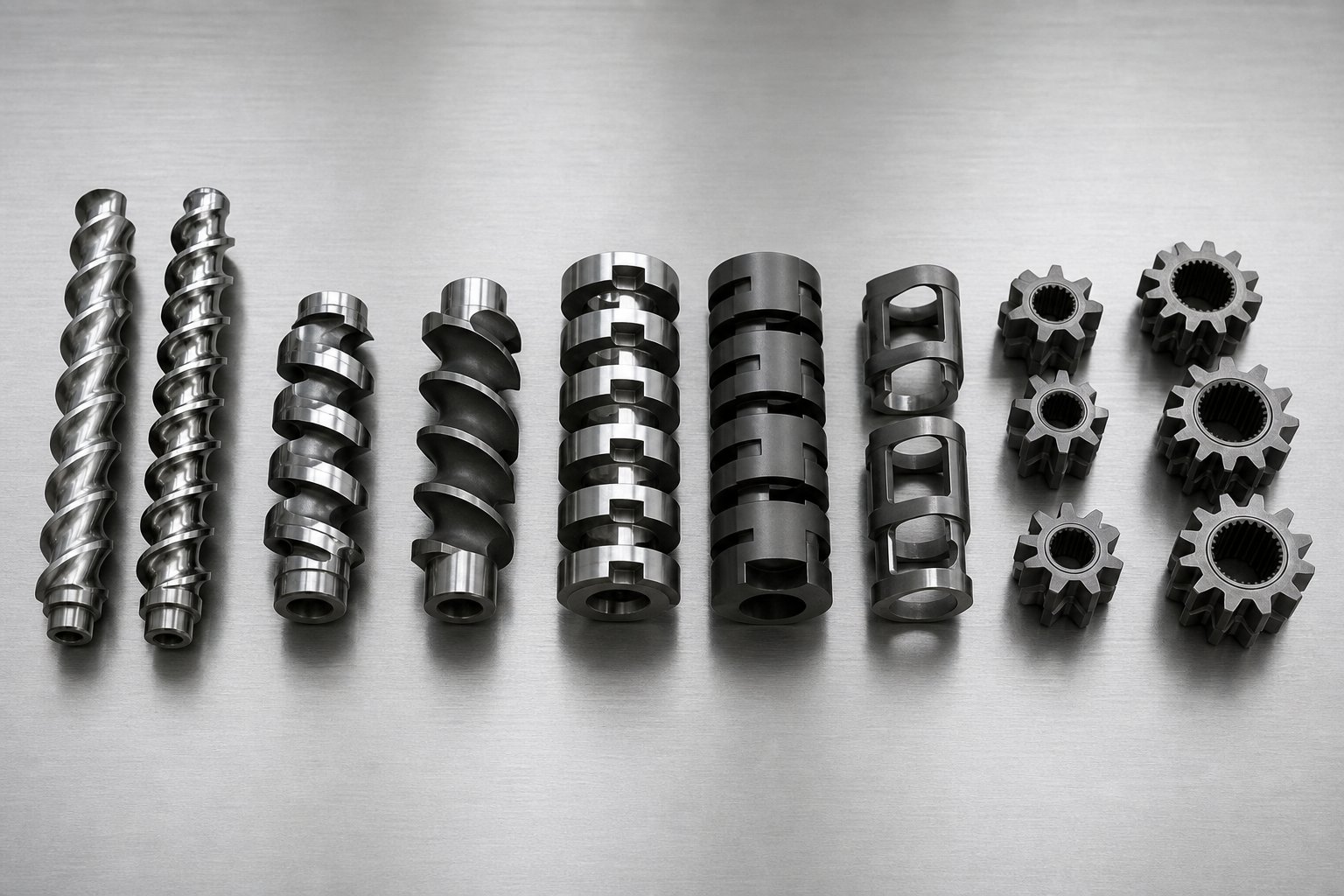
A lab co-rotating twin screw extruder ships with a default screw configuration. Most researchers run it as-is, at least initially. But here is what catalogs rarely explain: that default profile is a compromise designed to work reasonably well for a broad range of materials. It is not optimized for your specific polymer, your particular filler loading, or the exact shear window your experiment demands. The real capability of these machines lives in their modularity — the ability to slide individual screw elements on and off a keyed shaft, rearranging the processing profile in minutes. Understanding which elements do what, and how to sequence them, is arguably the most valuable skill a lab extrusion researcher can develop.
Understanding Screw Element Types
Every screw profile on a co-rotating twin screw extruder is assembled from a library of discrete elements, each with a specific job. The nomenclature varies between manufacturers — a Werner & Pfleiderer twin screw extruder uses different part codes than a Berstorff extruder or a Brabender system — but the functional categories remain consistent across the industry. Think of them as three families, each controlling a different aspect of how material behaves inside the barrel.
- Conveying elements (forward and reverse pitch): These are the workhorses of material transport. Forward-pitch conveying elements feature deep helical flights that move material toward the die with minimal shear input. Increasing the pitch (the distance between flights) increases the conveying rate, while shorter pitch elements slow material down and begin to build pressure. Reverse-pitch elements — sometimes called re-conveying or left-handed elements — push material backward, creating a deliberate restriction. This back-pressure is essential for sealing zones, such as isolating a vacuum vent from adjacent barrel sections.
- Kneading blocks (narrow, medium, and wide disc angles): Kneading blocks are stacked discs offset at specific angles relative to one another. The disc width and stagger angle determine whether the element favors distributive mixing (spreading components evenly) or dispersive mixing (breaking apart agglomerates under high stress). Narrow kneading discs promote distributive blending with moderate shear intensity. Wider discs generate substantially more dispersive shear, making them the go-to choice for breaking down pigment clusters or delaminating nano-clay platelets. The offset angle matters too: forward-staggered kneading blocks convey material while mixing, neutral (90-degree) blocks halt forward transport and maximize energy input, and reverse-staggered blocks actively push material backward for the most aggressive shear and longest local residence time.
- Specialized mixing elements (TME, ZME, and similar designs): Toothed mixing elements, often designated as ZME in systems descended from the Werner & Pfleiderer extruder platform, use rows of interlocking teeth rather than continuous flights. They excel at distributive mixing with very low dispersive shear, making them ideal for blending heat-sensitive components or achieving homogeneous color distribution without degrading the polymer matrix. Other specialized designs — such as screw mixing elements (SME) and turbine mixing elements (TME) — provide additional options for fine-tuning the balance between mixing intensity and material protection.
Each element type directly influences four critical processing variables: shear intensity, residence time, local pressure, and back-mixing behavior. A forward conveying element moves material quickly with low shear and low pressure buildup. A reverse kneading block does the opposite — it traps material, elevates shear stress, and builds pressure upstream. As NC State Extension's screw design guide puts it, designing a screw profile is a blend of art and science because no gold standard exists that optimizes flow for all materials and extruder geometries.
Designing a Screw Profile for Your Experiment
Imagine the screw shaft as a blank timeline. Your job is to arrange processing events along that timeline in a sequence that transforms raw ingredients into a uniformly compounded melt, without degrading anything along the way. Here is the general logic most experienced compounders follow.
Start with conveying. The first several elements after the feed opening are always forward-pitch conveying elements with generous flight depth. Their sole purpose is to grab incoming material — pellets, powder, or a combination — and transport it reliably into the barrel. Restricting flow too early causes feed-throat bridging and erratic torque. Keep this section open and simple.
Transition to melting. Once the material has been conveyed into the heated barrel, a sequence of kneading blocks initiates the solid-to-melt transition. The standard approach uses progressively more aggressive kneading: start with narrow, forward-staggered kneading discs for initial softening, then introduce wider or neutral-angle blocks where full melting is needed. The combination of barrel heat and mechanical shear generated in these blocks creates a fully molten stream. On a Berstorff extruder or similar lab platform, you might use three to five kneading elements in succession here, adjusting the total length depending on how easily your polymer melts.
Add mixing elements for blending. Downstream of the melt zone, distributive mixing elements — toothed elements, narrow kneading blocks at forward angles, or specialized mixing geometries — ensure that additives, fillers, and secondary polymers are spread uniformly through the melt. This is where side-fed components (glass fiber, mineral fillers, liquid additives) typically enter the barrel through a downstream feed port, and the screw profile must accommodate their incorporation without excessive fiber breakage or filler attrition.
Seal before the vent. If your process requires devolatilization, you need a pressure seal just upstream of the vent port. A short reverse-pitch conveying element or a reverse kneading block forces the screw to run completely full at that point, isolating the vacuum zone from the upstream barrel. Without this seal, vacuum pulls air backward through partially filled screw channels and devolatilization efficiency collapses. Downstream of the vent, the screw transitions back to conveying elements, and a second seal — often the die itself — prevents vacuum from disrupting the discharge section.
Build pressure for the die. The final elements are tight-pitch forward conveying elements that compress the melt, generate stable pressure, and push it through the die. Insufficient pressure buildup in this section causes pulsating output and inconsistent strand or film quality.
The beauty of a lab-scale co-rotating machine is how quickly you can rearrange this sequence. Screw elements slide onto a splined or keyed shaft and are held in place by a tip bolt. Swapping a neutral kneading block for a forward one, or adding a toothed mixing element where a conveying element used to sit, takes minutes with basic hand tools. This rapid reconfiguration is what makes the platform so powerful for systematic studies where you want to isolate the effect of a single processing variable — say, shear intensity in the mixing zone — while keeping everything else constant.
Configuration Examples for Common Research Tasks
There is no universal screw profile. Every formulation and research objective demands a tailored approach. However, a few general strategies give you a reliable starting framework.
Gentle blending (low shear): When you are working with thermally sensitive biopolymers, pharmaceutical dispersions, or shear-sensitive additives like long glass fibers, minimize the number and intensity of kneading blocks. Use primarily forward conveying elements with just enough narrow, forward-staggered kneading discs to achieve melting. Replace aggressive wide kneading blocks with toothed mixing elements that provide distributive blending without the high dispersive stress. Keep screw speed moderate. The goal is to melt and homogenize the material while preserving its molecular weight and structural integrity.
Intensive compounding (high shear): Nanocomposite research, aggressive pigment dispersion, and reactive extrusion often require the opposite approach. Stack multiple wide kneading blocks, include neutral (90-degree) stagger angles to maximize energy input, and consider a reverse kneading block at the end of the mixing section to extend local residence time. This configuration delivers the high shear stress needed to intercalate clay layers, deagglomerate carbon nanotube bundles, or drive melt-phase reactions to completion. Monitor torque and melt temperature closely — aggressive profiles push the motor harder and can overshoot the thermal processing window.
Devolatilization-focused profiles: For removing residual solvents, moisture, or reaction byproducts, the screw profile revolves around creating an effective vent zone. Position a short reverse element or reverse kneading block immediately upstream of the vent port to build the pressure seal. Follow it with forward conveying elements that keep the barrel partially filled under the vent opening, maximizing the surface area of melt exposed to vacuum. As devolatilization practitioners recommend, each vent stage can reduce volatile concentration by roughly an order of magnitude, so multi-vent configurations on higher L/D machines allow stepwise removal to very low residual levels.
The critical takeaway is this: your screw configuration is not a fixed feature of the machine. It is an experimental variable, one you control with the same intentionality as temperature, feed rate, or screw speed. Researchers who treat screw design as a static default leave significant performance on the table. Those who learn to read their material's response and adjust element placement accordingly unlock results that no off-the-shelf profile can deliver.
Of course, choosing the right screw layout also depends on understanding the broader platform choice — specifically, why co-rotating geometry dominates lab environments while counter-rotating machines serve a different niche entirely.
Co-Rotating vs Counter-Rotating Twin Screw Extruders Compared
You have two screws inside a barrel. They can either spin in the same direction or in opposite directions. Sounds like a minor detail, right? In practice, that single choice — co-rotating or counter-rotating — reshapes the entire flow field, dictates the mixing mechanism, and ultimately determines whether the machine belongs on your lab bench or in a PVC pipe plant. Most comparisons of co rotating and counter rotating twin screw extruder designs focus on industrial production. Here is why the distinction matters just as much, if not more, when you are working at lab scale with grams instead of tons.
Mechanical and Processing Differences
Picture the intermeshing region where the two screws meet. In a co-rotating design, both screws turn in the same direction. Material approaching the nip is swept around one screw, handed off to the other, and carried forward in an open, figure-eight flow path. This continuous handoff produces the self-wiping action that defines co-rotating geometry: the flight of one screw physically scrapes material from the root of the other, preventing stagnation and keeping the barrel interior clean. Intense shear fields develop both between the screws and between the screw and barrel wall, and the addition of kneading blocks introduces elongational flow components that further enhance mixing.
Counter-rotating screws tell a completely different story. Because the screws turn in opposite directions, material entering the intermeshing zone gets compressed between them rather than transferred. The result is a calendering effect — think of a two-roll mill squeezing material through a tight gap. This generates high localized pressure under relatively gentle shear conditions. Transport relies heavily on screw rotation itself, and the machine typically runs at a high degree of fill and comparatively low RPM. The lower shear stress means less viscous heat generation, which is exactly why counter-rotating extruders dominate rigid PVC processing, a material notorious for degrading under excessive thermal and mechanical stress.
The mechanical implications extend further. Co-rotating screws push the intermeshing region apart, distributing forces symmetrically across the barrel. Counter-rotating screws pull toward each other at the nip, concentrating wear and creating higher bearing loads. For a lab machine that needs to run reliably across dozens of different experimental formulations, the more balanced load distribution of the co-rotating design translates into longer component life and lower maintenance overhead.
Why Co-Rotation Dominates Lab and R&D Settings
Walk into virtually any polymer research lab, pharmaceutical development suite, or university extrusion facility and you will find a co-rotating machine. The reasons are practical, not theoretical.
Fast material changeovers. Lab researchers rarely run the same formulation all day. You might compound a nanocomposite in the morning, test a bioplastic blend after lunch, and run a color masterbatch trial before the day ends. The self-wiping geometry of the co-rotating design means residual material from the previous experiment is continuously scraped off internal surfaces during operation. Purging between runs is faster, cross-contamination risk drops, and you spend more time generating data than cleaning barrels.
Modular screw flexibility. As the previous section on screw configuration illustrated, co-rotating platforms use segmented, interchangeable elements on a splined shaft. You can reconfigure the entire processing profile — from gentle distributive mixing to aggressive dispersive compounding — in minutes. Counter-rotating machines, particularly conical designs, generally offer far less modularity. For a lab where the screw profile is itself an experimental variable, this difference is decisive.
Wider processing window. Co-rotating extruders handle a broader range of polymers, viscosities, and filler loadings without requiring fundamental hardware changes. The ability to independently control screw speed and feed rate through starve-feeding gives researchers fine-grained command over shear rate and residence time. Counter-rotating machines, optimized for specific material classes like rigid PVC, operate best within a narrower parameter space.
Superior mixing for compounding research. When your goal is to disperse nano-fillers, develop polymer alloys, or study reactive extrusion kinetics, the high-intensity mixing of co-rotating geometry is essential. The combination of shear fields at the screw-screw and screw-barrel interfaces, supplemented by kneading blocks and specialized mixing elements, delivers both dispersive and distributive mixing that counter-rotating calendering action simply cannot match. For a co extruder setup in a research environment, this mixing versatility is non-negotiable.
Does this mean counter-rotating machines have no place in a lab? Not entirely. If your research focuses specifically on PVC formulations, profile extrusion behavior, or processes that demand minimal shear, a counter-rotating lab extruder can be the right tool. But for the vast majority of R&D applications — polymer compounding, pharmaceutical hot-melt extrusion, bioplastics development, nanocomposite research — the co-rotating configuration is the clear standard.
The following table puts the key differences side by side:
| Criterion | Co-Rotating Twin Screw | Counter-Rotating Twin Screw |
|---|---|---|
| Self-Wiping Ability | Excellent — continuous self-cleaning action between intermeshing flights | Limited — calendering action does not produce equivalent self-wiping |
| Mixing Efficiency | High dispersive and distributive mixing through shear fields and kneading elements | Moderate — relies on compressive and elongational deformation at the nip |
| Pressure Generation | Moderate — adequate for die extrusion, not optimized for high-pressure forming | High — calendering effect generates strong localized pressure at low shear |
| Modularity | Highly modular — segmented screw elements allow rapid reconfiguration | Limited modularity, especially in conical designs |
| Ease of Cleaning | Fast purging and disassembly; self-wiping reduces residual buildup | Slower changeover; more manual cleaning typically required |
| Shear and Heat Input | Higher shear stress, controllable through screw design and RPM | Lower shear stress, better suited for thermally sensitive materials like rigid PVC |
| Typical Lab Applications | Polymer compounding, nanocomposites, pharmaceutical HME, bioplastics R&D, reactive extrusion | PVC formulation studies, profile extrusion research, low-shear processing trials |
Researchers sometimes ask whether used single screw extruders could serve as a budget alternative to either twin screw configuration. Single screw machines are simpler and cheaper, but they lack the positive conveying, self-wiping, and intensive mixing capabilities that make twin screw platforms viable for compounding research. A single screw is a melting and pumping device; a co-rotating twin screw is a mixing and compounding instrument. For serious formulation development, they are fundamentally different tools.
With the mechanical rationale for co-rotating geometry established, the natural next question is where, specifically, these machines make the biggest impact — across industries and research disciplines that stretch far beyond traditional plastics compounding.
Research Applications Across Industries and Disciplines
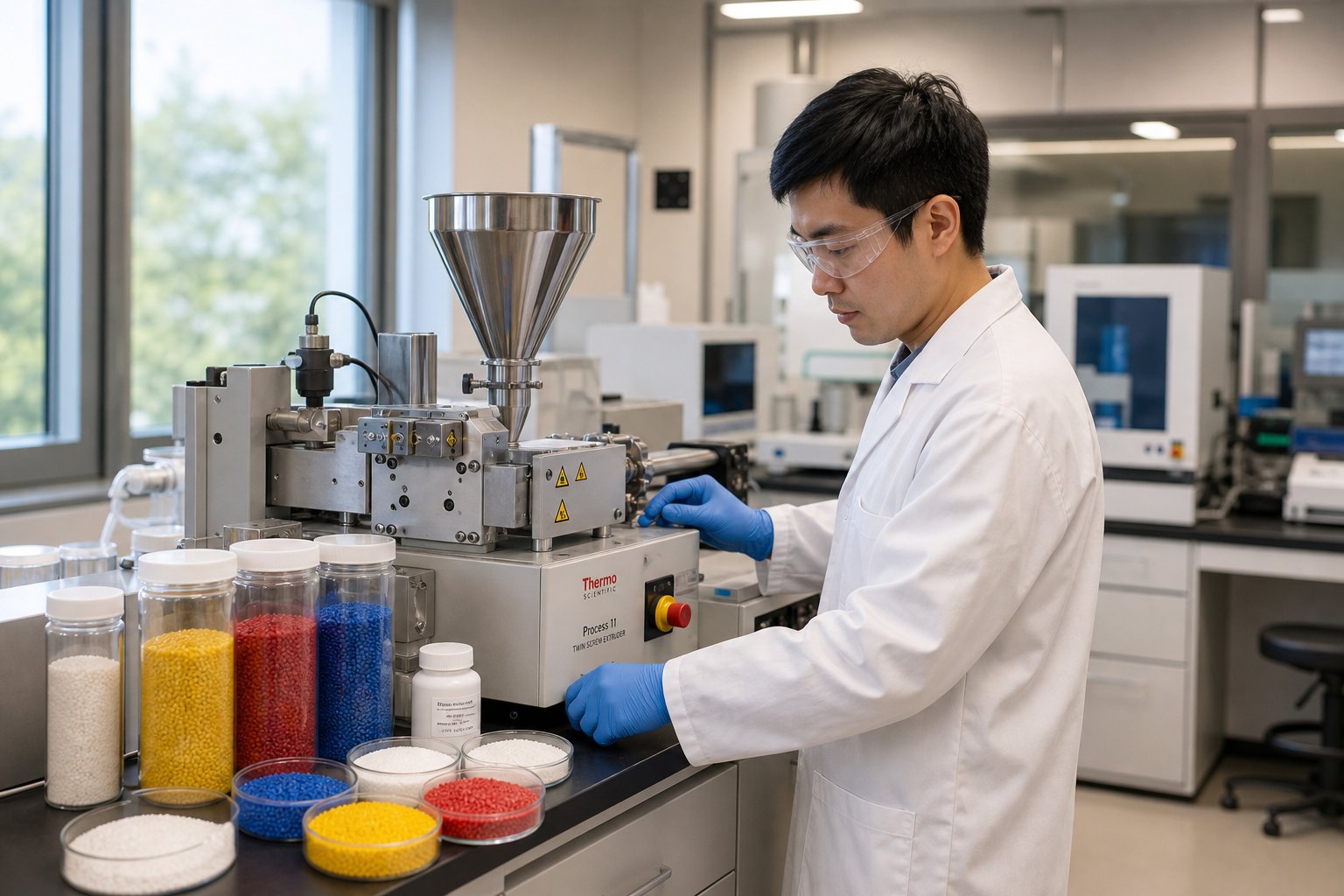
A lab co-rotating twin screw extruder is not a polymer-only tool. Its combination of precise thermal control, modular screw design, and small-batch capability makes it relevant wherever researchers need to melt, mix, react, or texturize materials under tightly controlled conditions. The growing twin screw extruders market reflects this breadth — demand stretches across pharmaceuticals, sustainable materials, advanced composites, food technology, and beyond. Here is how the machine earns its keep in each discipline.
Pharmaceutical Hot-Melt Extrusion Research
Poorly soluble drugs are one of the biggest challenges in pharmaceutical development. Hot-melt extrusion (HME) addresses this by molecularly dispersing an active pharmaceutical ingredient (API) into a polymer carrier, forming an amorphous solid dispersion (ASD) that dramatically improves bioavailability. The catch? APIs are expensive, often available in quantities of only a few hundred grams during early development.
Lab-scale co-rotating extruders solve this directly. A study published in AAPS PharmSciTech demonstrated systematic ASD development using a 9 mm co-rotating twin screw mini-extruder at batch sizes as small as 5 to 20 grams, then successfully scaled the process to 16 mm and 18 mm Leistritz extruders for clinical manufacturing — all with less than 500 grams of total API consumed. The PVP VA64-based dispersion achieved four-times higher bioavailability compared to crystalline tablet formulations in dog pharmacokinetic studies.
Precise temperature and shear control matters immensely here. Many APIs degrade above narrow thermal thresholds, and the screw profile must balance sufficient mechanical energy for dissolution in molten polymer against the risk of generating impurities. The same study found that even small changes — adding a surfactant during extrusion versus extra-granularly — shifted total impurity levels from 0.17% to over 9%. For pharmaceutical scientists, the lab extruder is not just a formulation tool; it is a process understanding instrument where every parameter can be isolated, measured, and optimized before committing to larger-scale batches.
Bioplastics and Sustainable Materials Development
Imagine you are developing a new PLA-based blend intended to replace conventional petroleum-derived packaging film. You have identified a promising bio-based toughening agent, but you need to find the right concentration, optimize the extrusion temperature profile, and characterize the resulting morphology — all before requesting pilot-line time that costs thousands of dollars per day.
This is exactly the workflow a lab co-rotating extruder enables. Recent research on PLA/poly(butylene sebacate) blends used a twin screw extrusion compounding process preceded by Design of Experiment simulations to optimize screw speed, feed rate, and temperature profile. The team varied PBSe content from 10 to 40 wt%, discovering that just 10 wt% PBSe delivered the highest fracture toughness improvement — roughly 7.5 kJ/m2 — outperforming other biopolymer tougheners like PCL and PBAT at equivalent loadings. Morphological analysis revealed that small, well-dispersed rubbery domains were essential; excessive PBSe caused coalescence and mechanical property degradation.
Researchers working with PHA, starch-based compounds, and natural fiber composites follow similar workflows. The lab extruder lets them screen dozens of formulation variants, map processing windows, and identify the blend ratios worth scaling up — all while consuming kilograms rather than tons of material.
Nanocomposite Compounding and Color Masterbatch
Dispersing nano-fillers uniformly through a polymer matrix is one of the most demanding compounding tasks. Whether you are working with nanoclay platelets, graphene nanosheets, or carbon nanotube (CNT) bundles, the challenge is the same: these materials arrive as tightly packed agglomerates that must be separated and distributed evenly at the nanoscale. Incomplete dispersion means inconsistent barrier properties, uneven conductivity, or mechanical weak points in the final product.
A lab co-rotating twin screw extruder configured with aggressive kneading blocks and optimized screw speed provides the high shear stress needed to intercalate or exfoliate nano-fillers. Because the screw profile is modular, researchers can systematically test how kneading block angle, sequence length, and RPM affect dispersion quality — then correlate processing parameters with TEM images, XRD patterns, or rheological data. Equipment platforms from manufacturers like Brabender and others offer the precision and modularity these studies demand, enabling reproducible results even at sub-kilogram batch sizes.
Color masterbatch development follows a parallel logic. Pigment loading, carrier resin selection, and dispersion quality all need optimization before committing to production quantities. Running small-batch trials on a lab co extruder setup lets colorists test dozens of pigment-to-carrier ratios in a single day, evaluating color strength, particle fineness, and filter pressure value with minimal material waste.
Food Science and Specialty Applications
Twin screw extrusion is a core technology in food processing, particularly for creating textured vegetable proteins (TVPs) used in plant-based meat analogues. A study using a co-rotating intermeshing twin screw extruder with an 11 mm screw diameter and 40:1 L/D ratio demonstrated that manipulating die temperature and screw speed directly controlled the expansion ratio, density, water absorption, and texture of soy protein isolate-based TVPs. Die temperatures above 200 degrees Celsius at moderate screw speeds yielded the most desirable sponge-like microstructures, while excessive thermal or mechanical energy degraded the protein network.
Beyond food texturization, lab extruders serve specialty niches including reactive extrusion of thermoset precursors, compounding of conductive polymer blends for electronics research, and development of medical-grade polymer composites. The common thread across all these applications is the same: small scale, high precision, and the ability to treat every processing parameter as an experimental variable.
For a quick reference, here are the key application domains where lab co-rotating twin screw extruders deliver the most research value:
- Pharmaceutical R&D — amorphous solid dispersions, hot-melt extrusion for bioavailability enhancement, continuous manufacturing process development
- Bioplastics and sustainable materials — PLA, PHA, and starch-based blend optimization, natural fiber composite development
- Nanocomposite compounding — clay, graphene, and CNT dispersion studies requiring controlled high-shear processing
- Color masterbatch development — pigment loading trials, carrier resin screening, and dispersion quality testing
- Food science — textured protein extrusion, snack puff development, and starch modification research
- Specialty polymer research — conductive blends, reactive extrusion, medical-grade composites, and advanced fiber-reinforced systems
Each of these disciplines generates rich processing data at lab scale — torque curves, specific energy inputs, melt temperature profiles, and residence time distributions. That data does not just serve the immediate experiment. It becomes the foundation for one of the most critical, and least discussed, challenges in extrusion research: scaling up from a 16 mm lab barrel to a 50 mm or larger production machine without losing what made the formulation work in the first place.
Scaling Up from Lab Extruder to Production Line
Here is the uncomfortable truth about lab extrusion: generating beautiful data on a 16 mm or 26 mm machine means nothing if that formulation falls apart the moment it hits a 92 mm production extruder. Torque curves flatten, melt temperatures drift, pressure fluctuations appear out of nowhere, and the pellets that looked flawless at lab scale suddenly show phase separation or unmolten material. The jump from lab to production is where promising research either becomes a commercial product or dies quietly in a troubleshooting log.
Yet catalogs for lab co-rotating twin screw extruders almost never discuss scale-up. They list specifications, show pellet photos, and stop. The assumption seems to be that scaling is someone else's problem. In reality, the entire value of a lab extruder hinges on how reliably its data predicts production-scale behavior. Understanding the principles, pitfalls, and proven strategies of scale-up transforms your lab machine from a standalone research tool into the first link in a commercial manufacturing chain.
Why Lab-Scale Data Is Essential for Scale-Up
Every experiment you run on a lab extruder generates process data that production engineers will eventually need. The question is whether you collect it deliberately or scramble to reconstruct it later. Four parameters matter most.
Specific mechanical energy (SME) is the single most important scale-up reference point. It quantifies the energy per unit mass transferred from the motor, through the screws, and into your compound. SME is calculated from motor torque, screw speed, and throughput rate. When you optimize a formulation on a 26 mm machine and record an SME of, say, 0.083 kWh/kg, that number becomes your target for every larger extruder downstream. A Dow case study on masterbatch scale-up demonstrated this directly: initial runs on a 40 mm pilot extruder produced phase-separated, unpelletizable material at an SME of only 0.055 kWh/kg — roughly 34% below the lab-scale benchmark. Only after adjusting screw design, temperature profile, and screw speed to bring SME back to 0.079 kWh/kg did the process stabilize and produce homogeneous pellets.
Residence time distribution (RTD) captures how long material spends inside the barrel and how broadly that time varies across the melt stream. Two formulations can have identical average residence times but completely different distributions — one narrow and uniform, the other broad with long tails indicating stagnation. Pharmaceutical HME scale-up research using 11 mm, 16 mm, and 24 mm co-rotating extruders showed that matching RTD across scales required adjusting feed rate beyond what simple geometric scaling predicted — the residence time matched perfectly only when specific mechanical energy consumption (SMEC) was also matched.
Melt temperature profiles reveal how much thermal energy the compound absorbs from barrel heaters versus viscous dissipation. At lab scale, barrel heating dominates. At production scale, mechanical shear contributes proportionally more, often pushing melt temperatures higher than expected. Recording zone-by-zone melt temperatures during lab trials gives you a thermal baseline that production engineers can use to anticipate — and prevent — overheating.
Torque measurements indicate how hard the motor works to process your formulation. Torque trends during lab runs expose whether you are operating near the motor's capacity limit and how much headroom exists for production machines with different drive characteristics. Sudden torque spikes also flag feeding instabilities or formulation incompatibilities that will only worsen at larger scale.
Geometric similarity ties all of this together. When your lab and production extruders share similar L/D ratios and outer-diameter-to-inner-diameter (OD/ID) ratios, the flow patterns, shear fields, and mixing mechanisms remain comparable across scales. The Dow study used 26 mm, 40 mm, and 92 mm extruders that were all co-rotating, fully intermeshing, and geometrically similar — with an L/D ratio of 44 and an OD/ID ratio of 1.55 across all three sizes. This consistency is what made SME a reliable bridge between scales.
Common Scale-Up Challenges and Strategies
If scaling up were simply a matter of running a bigger machine at the same settings, every lab formulation would translate flawlessly to production. It does not work that way, and the reasons are rooted in physics.
Heat transfer shifts dramatically with barrel diameter. The area-to-volume (A/V) ratio of a twin screw extruder decreases as the diameter increases. A 26 mm lab barrel has a large surface area relative to the small volume of melt inside it, so barrel heaters and cooling jackets exert tight thermal control. Scale to a 92 mm barrel and that ratio shrinks significantly. The barrel surface can no longer inject or remove heat as efficiently per unit of material. This is why production extruders often rely more heavily on mechanical energy input — and why temperature profiles optimized on a lab machine cannot simply be copied to a larger one.
Shear rate changes at constant tip speed. A common scale-up rule maintains constant screw tip speed (the product of screw diameter and RPM) across machine sizes. But shear rate in the channel depends on the gap between screw and barrel, which does not scale linearly with diameter. Running a production extruder at the same RPM as the lab machine typically reduces shear rate, resulting in under-mixed or under-melted material. The Dow case study illustrated this vividly: applying lab-optimized conditions directly to the 92 mm extruder produced solid, unmolten polymer pellets exiting through the diverter valve, with an SME of only 0.026 kWh/kg — 69% below the lab benchmark.
Feeding behavior evolves unpredictably. Materials that flow smoothly into a 16 mm feed throat can bridge, flood, or segregate when gravity and hopper geometry change at larger scale. Bulk density variations, electrostatic charging, and moisture absorption all behave differently at higher throughput rates. Gravimetric feeders that performed flawlessly at 500 grams per hour may require completely different calibration at 50 kilograms per hour.
The practical response to these challenges is volumetric scale-up — using the cube of the diameter ratio to estimate the maximum throughput rate if the process is power/volume limited, or the square of the diameter ratio if heat transfer is the constraint. For geometrically similar extruders, the power/volume approach (rate scales with D3) gives the theoretical maximum. The heat-transfer approach (rate scales with D2) gives a more conservative estimate when thermal control is tight.
Simply increasing screw speed on the bigger machine to compensate for lower shear does not replicate lab conditions — it changes residence time, fill level, and energy dissipation patterns simultaneously. Instead, experienced process engineers adjust multiple variables together: screw design (more aggressive mixing sections), temperature profile (often cooler barrel settings to offset viscous heating), and throughput rate, always checking whether the resulting SME falls within the range validated at lab scale.
Matching specific mechanical energy across scales is not just a rule of thumb — it is the most reliable single-parameter indicator that your compound is receiving equivalent processing intensity, regardless of extruder size. When SME drifts, product quality follows.
From Pilot Line to Full Production
The typical commercialization pathway follows three stages, and skipping any of them dramatically increases risk.
Stage 1: Lab-scale formulation and optimization. This is where you develop the recipe, optimize screw configuration, identify the processing window, and collect baseline SME, RTD, melt temperature, and torque data. A well-instrumented lab co-rotating twin screw extruder — even a modest 16 mm or 20 mm unit — generates all the foundational data needed for subsequent scaling. The Dow masterbatch study achieved its optimized SME of 0.083 kWh/kg entirely on a 26 mm machine before attempting any scale-up.
Stage 2: Pilot-line validation. Intermediate-scale extruders, typically in the 35 to 50 mm range, serve as a proving ground. They reveal heat transfer limitations, feeding issues, and process instabilities that the lab machine's favorable A/V ratio masked. This stage is also where you generate customer samples, conduct application testing, and confirm that product quality holds at higher throughput. The pharmaceutical scale-up study found that moving from an 11 mm to a 16 mm extruder required only a feed rate adjustment, but scaling further to a 24 mm system demanded both feed rate and screw speed changes — illustrating how each scale transition introduces new constraints.
Stage 3: Production transfer. Armed with validated processing parameters from both lab and pilot stages, the production team configures the full-size machine (often 65 mm and above) to match the proven SME target. Even at this stage, adjustments are common. Root-cause analysis may reveal material behaviors — like the lubricating effect that disrupted the 92 mm Dow trial — that only become apparent at production barrel diameters. The key is that these adjustments are guided by quantitative benchmarks from earlier scales, not guesswork.
Labs sometimes face budget constraints that make acquiring new pilot or production equipment impractical. In these situations, sourcing used extrusion equipment for intermediate-scale trials can be a pragmatic option. Reliable used extrusion equipment for sale from reputable dealers can provide the pilot-line capability needed for validation without the capital outlay of a new machine. A quality used extruder with verified screw element availability and a compatible control system bridges the gap between lab discovery and production commitment — provided you verify barrel wear, drive condition, and geometric similarity to your lab platform before purchasing.
What matters most across all three stages is continuity of data. The SME you measure on your lab extruder, the RTD you characterize at pilot scale, and the torque profiles you monitor in production are chapters of the same story. Break that chain — by skipping pilot validation, by failing to record lab-scale baselines, or by switching to a geometrically dissimilar extruder family — and you risk learning lessons on the production floor that should have been learned on the benchtop.
Scale-up strategy, however, is only one piece of the broader decision matrix. Choosing the right lab machine in the first place — balancing screw diameter, modularity, vendor support, and budget — is what sets the entire development program up for success or frustration.
How to Choose the Right Lab Twin Screw Extruder
Knowing the theory behind scale-up, screw configuration, and processing zones is essential — but eventually every researcher faces a more immediate question: which machine do I actually buy? The answer depends on a tangle of factors that catalogs treat as obvious but rarely explain. Budget, screw diameter, vendor support, barrel modularity, and even whether to buy new or used all compete for priority. Getting this decision right determines whether your lab runs smoothly for years or becomes a case study in expensive regret.
New vs Used Lab Extruder Considerations
For well-funded corporate R&D centers, purchasing a new lab co-rotating twin screw extruder is the straightforward path. You get a full manufacturer warranty, the latest control system software, custom barrel and screw configurations matched to your application, and direct vendor support for troubleshooting. Lead times can stretch to several months, but the tradeoff is a machine delivered exactly to your specifications.
Budget-conscious labs — university departments, startup material companies, or pilot programs with limited capital — often explore the used twin screw extruder market. Reliable used extruders for sale from reputable dealers can cut acquisition costs by 30 to 60 percent compared to new equipment. That discount, however, comes with risks that demand careful due diligence.
Pros of Buying Used
- Significantly lower upfront investment, freeing budget for materials, feeders, or downstream equipment
- Faster delivery — used extruder equipment is typically available immediately rather than requiring months of manufacturing lead time
- Proven operational history in some cases, with maintenance records that confirm reliability
Cons and Risks of Buying Used
- Screw element availability: Modular screw elements are proprietary to each manufacturer. If the original manufacturer has discontinued the model or changed element geometry, sourcing replacement conveying elements, kneading blocks, or specialized mixing elements becomes difficult and expensive. Verify element availability before committing.
- Barrel condition: Worn barrel liners reduce mixing efficiency and processing consistency. Ask for bore diameter measurements at multiple points along the barrel length. Even minor wear at lab scale — where clearances between screw and barrel are measured in tenths of a millimeter — can degrade performance noticeably.
- Control system compatibility: Older PLC platforms may lack modern data logging, recipe storage, or communication protocols. Retrofitting an outdated control system can cost nearly as much as the used twin screw extruder for sale price itself, erasing the savings that motivated the purchase.
- Gearbox and drive condition: The gearbox is the most expensive single component in any twin screw extruder. Request torque test data or, ideally, a supervised test run under load before purchasing. Worn bearings or damaged gear teeth are not visible from the outside.
A practical middle ground exists for labs that want the cost savings of used extruders without the risk: purchase the base machine used, then invest in new screw elements and barrel liners from a vendor who can manufacture to the original specifications. This approach delivers a mechanically sound platform with fresh wear components at a fraction of full new-equipment pricing.
Key Selection Criteria for Lab Buyers
Whether you are buying new or sourcing used equipment, the same technical criteria determine whether the machine fits your research program. The table below distills these into a practical evaluation framework.
| Selection Criterion | What to Look For | Why It Matters |
|---|---|---|
| Screw Diameter Range | 12 – 26 mm for lab scale; consider 35 mm+ if pilot-scale trials are anticipated | Determines minimum batch size and maximum throughput; smaller diameters conserve expensive or scarce materials |
| L/D Ratio Options | At least 32:1; 40:1 or 48:1 preferred for complex processing tasks | Higher L/D provides more barrel real estate for additional mixing, feeding, or devolatilization zones |
| Torque Capacity | Sufficient Nm/cm3 for your highest-viscosity target material; verify overload protection is included | Inadequate torque causes motor stalls during high-fill or high-viscosity formulations, limiting your experimental range |
| Maximum RPM | 300 – 600+ RPM with variable frequency drive for precise adjustment | Controls shear rate and mechanical energy input; wider RPM range supports both gentle blending and intensive compounding |
| Number of Barrel Zones | 6 – 10 independently heated and cooled zones for lab machines with L/D of 40:1 | More zones enable sharper temperature transitions and finer thermal profiling for multi-stage experiments |
| Control System Sophistication | PLC with touchscreen HMI, PID temperature control (±1 °C), data logging, recipe storage, and export capability | Reproducible experiments require precise parameter recording; data export enables systematic analysis and scale-up planning |
| Modularity of Screw and Barrel | Segmented barrel sections with quick-open or clamshell access; keyed or splined screw shaft accepting interchangeable elements | Rapid reconfiguration is the core advantage of a lab platform — limited modularity defeats the purpose of lab-scale work |
| Vendor Support for Custom Configurations | Ability to design and supply application-specific screw elements, custom barrel ports, and specialized mixing geometries | Off-the-shelf configurations rarely optimize novel materials; custom design support accelerates results for unconventional formulations |
That last row — vendor support for custom configurations — deserves special attention. Many labs purchase a capable machine but then struggle because the standard screw element library does not address their specific material challenges. A bioplastic researcher working with high-starch formulations needs different kneading geometries than a pharmaceutical team extruding amorphous solid dispersions. Labs processing specialty or experimental materials benefit enormously from vendors who offer custom screw and barrel design services tailored to their formulations and compact equipment constraints. NANHAIYA's Custom Screw Design Services, for example, support R&D labs, universities, and pilot-line operators who need application-specific screw elements and barrel configurations designed around their unique materials — a service that can make the difference between months of trial-and-error and a screw profile that works from the first run.
Practical Tips for Lab Changeover and Maintenance
A lab extruder that cannot be cleaned quickly between experiments is a lab extruder that wastes research hours. When you are switching from a carbon-black-filled compound to a transparent PLA blend, even trace contamination ruins the next batch. Yet changeover and maintenance procedures are among the least-discussed topics in extruder buyer guides.
Purging between materials. The fastest cleanup method is processing a purging compound through the machine before switching formulations. Commercial purging compounds — available in grades optimized for different temperature ranges and polymer types — scour residual material from screw channels, barrel walls, and die passages. For labs running frequent changeovers, a two-step purge often works best: first, a high-viscosity resin (such as HDPE) to physically push out bulk residual material, followed by a specialized purging grade that chemically loosens any remaining deposits. Davis-Standard's maintenance guidelines recommend running the purge at 25 to 40 percent of normal operating speed for best cleaning action.
Barrel disassembly for thorough cleaning. When purging alone is insufficient — for example, after processing highly pigmented masterbatches or thermally degraded materials — full disassembly is necessary. Lab extruders with quick-open barrel designs or clamshell barrel housings make this practical. Remove the screw assembly, pull individual screw elements off the shaft, and clean each one separately with brass or copper tools that will not scratch hardened steel surfaces. Inspect barrel liner surfaces for scoring, buildup, or discoloration that indicates wear. The barrel's quick-open structure is specifically highlighted by manufacturers as a key feature that simplifies cleaning and reduces downtime between formula trials.
Screw element inspection. Each time you disassemble the screw, inspect kneading blocks and mixing elements for edge wear, chipping, or surface erosion. Worn kneading disc edges lose their ability to generate consistent shear, introducing variability into experiments that should be reproducible. Replace worn elements before they compromise data quality — not after you have spent a week troubleshooting inconsistent dispersion results.
Use the following checklist as a routine maintenance guide:
- Purge the barrel with appropriate purging compound after every material change
- Inspect screw elements for edge wear, surface erosion, and buildup at least monthly or after every 40 hours of operation
- Measure barrel bore diameter at the feed zone, mixing zone, and die end quarterly to track liner wear
- Verify thermocouple accuracy by cross-checking zone temperatures with a calibrated probe at least twice per year
- Lubricate gearbox per manufacturer schedule and check oil for metal particles that indicate gear or bearing wear
- Clean vacuum vent ports after each run to prevent blockages that degrade devolatilization performance
- Inspect and clean feeder mechanisms — especially loss-in-weight feeder load cells and auger flights — to maintain dosing accuracy
- Test emergency stop and overload protection systems monthly
- Document all maintenance actions, screw configurations, and barrel measurements in a log tied to each experiment for traceability
Consistent maintenance is not glamorous, but it is what separates labs that produce publishable, reproducible data from labs that constantly chase ghost variables. A well-maintained machine with the right screw configuration — whether sourced from the original equipment manufacturer or designed by a specialized vendor like NANHAIYA — delivers consistent performance run after run, which is ultimately the entire point of investing in a lab-scale platform.
Equipment selection and upkeep, however, are just the infrastructure. The real question is how to translate all of these decisions — screw design, machine selection, maintenance discipline — into a cohesive lab extrusion program that accelerates your research and delivers results no off-the-shelf setup can match.
Maximizing Your Lab Extrusion Results with the Right Setup
You have the machine, the spec sheet makes sense, and the maintenance log is up to date. Yet somehow, the compound coming out of the die still does not match what your simulation predicted. The pellets look fine under visual inspection, but TEM images reveal patchy filler dispersion. Or the melt temperature keeps climbing past the degradation threshold of your experimental biopolymer, no matter how you adjust barrel zone settings. Sound familiar?
More often than not, the bottleneck is not the extruder itself. It is the screw configuration — specifically, the gap between what a standard element library offers and what your particular material actually needs. Closing that gap is where lab extrusion shifts from routine processing to genuine discovery.
Why Custom Screw Design Unlocks Lab Extruder Potential
Every lab co-rotating twin screw extruder ships with a standard set of conveying elements, kneading blocks, and perhaps a handful of mixing elements. For conventional polymer compounding — blending well-characterized resins with common fillers — those standard elements perform adequately. The trouble starts when your research pushes into territory the original equipment manufacturer did not anticipate.
Consider a few real-world scenarios. A pharmaceutical team developing an amorphous solid dispersion with a thermally labile API needs kneading blocks that deliver sufficient dispersive energy to dissolve the drug in a polymer carrier, but at substantially lower peak shear stress than standard wide-disc blocks generate. A bioplastics researcher compounding high-starch formulations encounters excessive torque spikes because the standard conveying elements cannot handle the rheological behavior of partially gelatinized starch. A nanocomposite group working with graphene nanoplatelets finds that standard 60-degree kneading blocks provide either too much shear (damaging the platelets) or too little (leaving agglomerates intact), with nothing in between.
In each case, the machine is perfectly capable. The screw elements are the limiting factor. Off-the-shelf configurations represent a manufacturer's best guess at what most users need — a reasonable compromise, but a compromise nonetheless. When you are investigating novel materials, unconventional formulations, or niche processing windows, that compromise can cost months of trial-and-error cycling through standard element combinations that were never designed for your specific challenge.
Custom-designed screw elements change the equation entirely. A toothed mixing element with modified tooth geometry can deliver the exact dispersive-to-distributive mixing ratio your nano-filler demands. A kneading block with a non-standard disc angle — say 45 degrees instead of the typical 30, 60, or 90 — can thread the needle between adequate melting and thermal degradation for a heat-sensitive compound. Conveying elements with adjusted channel depth can accommodate the unusual bulk density of a bio-based powder that standard flights cannot grip reliably.
The key insight is this: your screw profile is not just a machine setting. It is an integral part of your experimental design. Treating it as a fixed constraint rather than a designable variable leaves performance on the table — performance that no amount of temperature adjustment or RPM tweaking can recover. As screw design specialists emphasize, the screw configuration shapes the character of the process more strongly than the extruder itself. The same machine behaves in completely different ways once the screw formation changes.
Building Your Lab Extrusion Capability
Whether you are setting up a brand-new extrusion lab or upgrading an existing one, a systematic approach prevents expensive missteps. Jumping straight to equipment procurement — browsing listings for a twin screw extruder for sale or comparing twin screw extruder price quotes — before defining your research scope is like buying a camera before deciding what you want to photograph. The lens selection, sensor size, and accessory kit all depend on the subject matter.
Here is a step-by-step framework that experienced lab managers follow when building or expanding their extrusion capability:
- Define your research objectives clearly. Are you optimizing formulations for scale-up? Screening dozens of blend ratios? Running reactive extrusion with long residence times? Your objectives dictate every downstream decision — screw diameter, L/D ratio, barrel zone count, and downstream equipment needs.
- Select the appropriate screw diameter and L/D ratio. Match diameter to your typical batch size and material availability. A 16 mm machine conserves precious materials; a 26 mm platform bridges toward pilot scale. Choose an L/D ratio that accommodates all the processing zones your experiments require — melting, mixing, side feeding, devolatilization — with room for future expansion.
- Invest in a comprehensive modular screw element library. Do not settle for the minimum kit. Purchase conveying elements at multiple pitch lengths, kneading blocks across the full range of disc widths and stagger angles, and at least one type of specialized mixing element. The broader your element inventory, the more experimental configurations you can test without waiting weeks for new parts to arrive.
- Partner with a vendor that understands lab-scale constraints. Production-focused suppliers sometimes treat lab equipment as a scaled-down afterthought. Seek out vendors who actively support small-batch processing with custom screw and barrel design capabilities. NANHAIYA's Custom Screw Design Services exemplify this approach — their team works directly with R&D labs, universities, and pilot-line operators to design application-specific screw elements and barrel configurations for specialized materials and compact extruders. Having a design partner who can translate your material's rheology into optimized screw geometry shortens the path from concept to publishable results.
- Establish rigorous data collection protocols from day one. Record SME, torque, melt temperature, screw speed, feed rate, and screw configuration for every run. This discipline transforms isolated experiments into a coherent dataset that supports scale-up, publication, and reproducibility — the three pillars of lab extrusion value.
- Plan for eventual scale-up. Even if production is years away, choose a lab extruder whose geometry (L/D ratio, OD/ID ratio) aligns with the production platforms common in your target industry. Geometric similarity between your lab and future pilot or production machines makes scale-up data transfer far more reliable.
This sequence is not arbitrary. Each step builds on the previous one, creating a foundation that supports not just your current project but every future study that passes through the lab. Researchers who skip the planning stages — purchasing a plastic extruder machine for sale because the price was right, rather than because the specifications matched their needs — inevitably spend more time and money compensating for the mismatch than they saved on the initial purchase.
The same logic applies to labs shopping the secondary market. If you are evaluating plastic extruders for sale or browsing twin screw extruders for sale listings, run every candidate through the selection criteria table from the previous chapter before making an offer. A bargain machine with incompatible screw geometry, an obsolete control system, or no path to custom element sourcing is not a bargain at all.
The most impactful upgrade most labs can make is not a bigger motor or a faster control system — it is a screw profile engineered for their specific materials, designed by someone who understands both the polymer science and the mechanical constraints of compact, lab-scale equipment.
A lab co-rotating twin screw extruder is more than a piece of hardware. It is the starting point for every formulation that will eventually become a commercial product, a published finding, or a patented process. The researchers who extract the most value from these machines are the ones who treat every component — from feeder calibration to screw element selection to maintenance discipline — as part of an integrated system designed to generate reliable, scalable data. And when standard components reach their limits, a design partnership with a specialist like NANHAIYA turns the extruder from a general-purpose tool into a precision instrument matched to the exact demands of your research.
Frequently Asked Questions About Lab Co-Rotating Twin Screw Extruders
1. What is the typical screw diameter range for a lab co-rotating twin screw extruder?
Lab co-rotating twin screw extruders generally use screw diameters between 12 mm and 26 mm. A smaller diameter such as 16 mm allows meaningful experiments with as little as 50 to 100 grams of material, making it ideal for costly APIs or scarce experimental polymers. Larger diameters like 26 mm handle bigger batches and serve as a bridge toward pilot-scale validation. The diameter you choose sets both the minimum sample size per run and the maximum throughput ceiling, so matching it to your typical batch requirements and material availability is the first decision in any equipment evaluation.
2. How does a co-rotating twin screw extruder differ from a counter-rotating one for lab use?
In a co-rotating design, both screws turn the same direction, creating a figure-eight flow path with continuous self-wiping action that prevents material stagnation and simplifies cleaning between experiments. Counter-rotating screws turn in opposite directions, generating high calendering pressure at the nip but offering limited self-cleaning and less screw modularity. For R&D environments where researchers switch formulations frequently and need to reconfigure screw profiles for different experiments, co-rotating machines dominate because they offer faster changeovers, broader processing windows, and superior dispersive and distributive mixing capabilities essential for compounding research.
3. Why is specific mechanical energy (SME) important when scaling up from a lab extruder?
SME quantifies the mechanical energy transferred from the motor through the screws into each kilogram of compound. It serves as the most reliable single-parameter bridge between lab-scale and production-scale processing. When you record an optimized SME value on your lab machine, that number becomes the target for every larger extruder in the scale-up pathway. If SME drifts significantly during scale-up — due to changes in heat transfer, shear rate, or screw design — product quality deteriorates, often manifesting as phase separation, incomplete melting, or inconsistent dispersion. Tracking SME from the very first lab run creates a quantitative benchmark that guides every subsequent scale transition.
4. Can I use custom screw elements in a lab twin screw extruder?
Yes, and doing so is often the most impactful upgrade a lab can make. Standard screw element libraries represent a manufacturer's general-purpose compromise, which works for conventional compounding but falls short for novel materials, unconventional formulations, or narrow processing windows. Custom-designed elements — such as kneading blocks with non-standard disc angles or toothed mixing elements with modified geometry — let you match the screw profile precisely to your material's rheology and processing needs. Vendors like NANHAIYA offer custom screw design services specifically for R&D labs and pilot-line operators working with specialized materials on compact extruders, shortening the path from concept to optimized results.
5. What maintenance tasks are most critical for a lab twin screw extruder?
The highest-priority maintenance tasks include purging the barrel with a suitable purging compound after every material change to prevent cross-contamination, inspecting screw elements for edge wear and surface erosion at least monthly or every 40 operating hours, and measuring barrel bore diameter quarterly to track liner wear. Thermocouple accuracy should be verified with a calibrated probe twice per year, and gearbox oil should be checked for metal particles on the manufacturer's recommended schedule. Vacuum vent ports need cleaning after each run to maintain devolatilization performance. Documenting every maintenance action alongside screw configurations and barrel measurements ensures traceability and supports reproducible experimental results.
Written by
Nanhaiya Technical Team
Zhoushan Nanhaiya Plastic Machinery Co., Ltd.
The Nanhaiya technical team supports screw and barrel manufacturing projects through application review, technical communication, custom manufacturing coordination, and production and quality control.
Discuss Your Application
Related Articles
More insights on screw barrel technology and plastics processing.

What Nobody Tells You About Screw Barrel For Plastic Machine Design
Oct 10, 2026
Learn how screw barrel for plastic machine design affects melt quality, throughput, and wear life. Covers geometry, resin matching, troubleshooting, and sourcing.
Read Article
Single Screw Extruder for Sheet: Stop Guessing, Start Specifying
Oct 9, 2026
Learn how to specify a single screw extruder for sheet production. Covers screw geometry, resin-specific processing, troubleshooting, and maintenance best practices.
Read Article
PE Pipe Extruder Machine: What Datasheets Won't Tell You
Oct 9, 2026
Learn how a PE pipe extruder machine works, key specs explained, material grade selection, maintenance tips, and buyer guidance beyond the datasheet.
Read ArticleLooking for something else?
Search by material, symptom or product and jump straight to the relevant page.
These are navigation suggestions based on keyword matching — not a quotation, not a delivery commitment, and not a substitute for engineering review. Final specification is confirmed by our engineers against your drawings and processed material.
Need help with screw barrel selection?
Share your machine model, processed material and application. Our team can help with pricing and technical support.