

What Is a Kneading Block and Why It Matters
If your extrudate quality is inconsistent, your melt temperatures are drifting, or you're battling undispersed fillers, there's a good chance the answer sits right on your screw shaft. The kneading block is the single most influential element in a co-rotating twin screw extruder, and small configuration mistakes can cascade into major process headaches.
What Is a Kneading Block in Twin Screw Extrusion
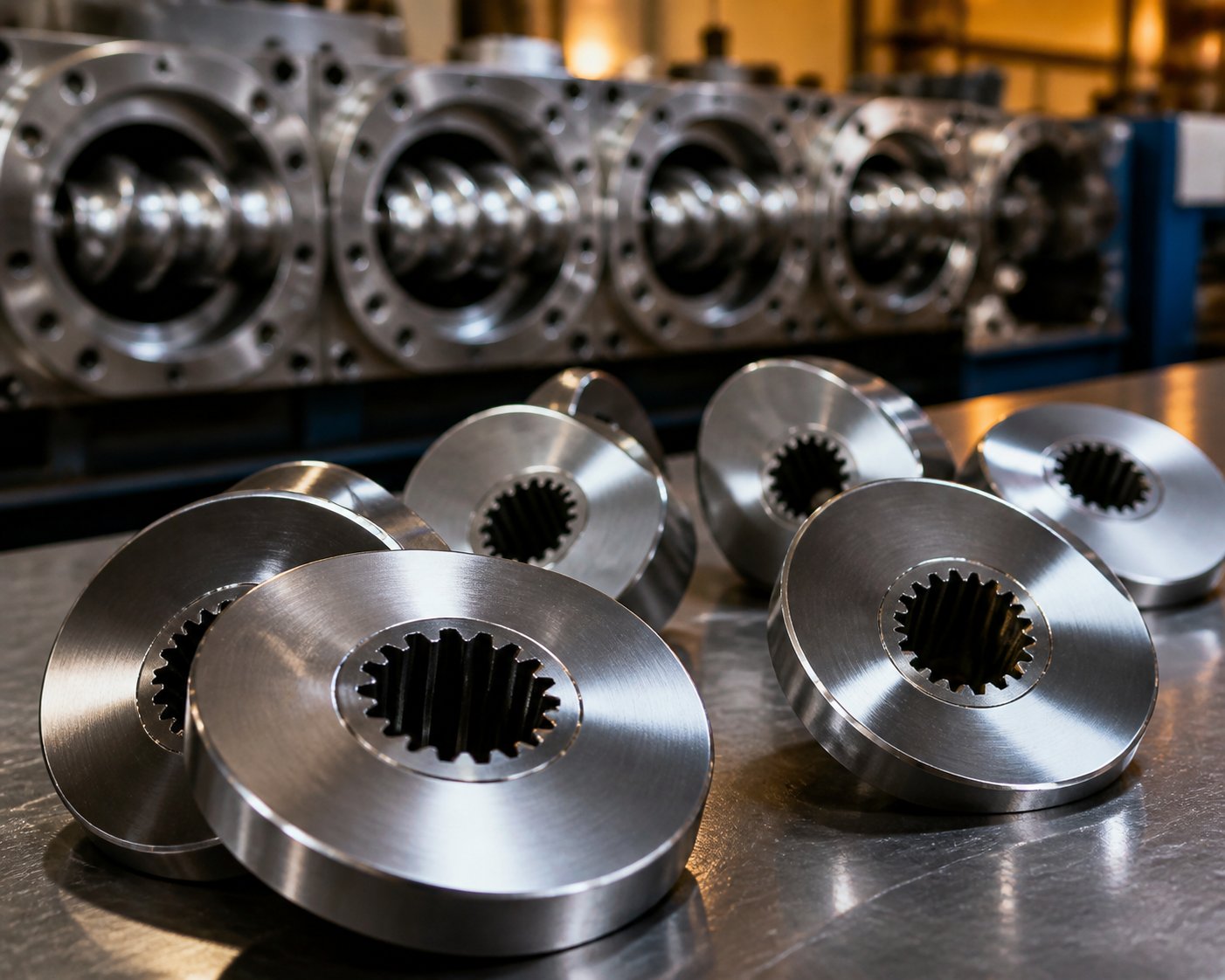
Imagine a series of elliptical discs stacked along a shared spline shaft, each disc deliberately offset at an angle from its neighbor. That's a kneading block — a modular screw element engineered to apply shear, heat, and mixing energy to polymer melts and other process materials. While conveying screw elements use helical flights to transport material downstream with minimal energy input, kneading blocks work differently. Their disc-to-disc offset forces the melt through narrow gaps, stretching and folding it repeatedly to generate the intense mechanical work that conveying elements simply cannot deliver.
A kneading block is a series of elliptical discs mounted at staggered offset angles on a spline shaft within a co-rotating twin screw extruder. It serves as the primary mixing element, responsible for both dispersive mixing (breaking down agglomerates and droplets) and distributive mixing (homogenizing the spatial distribution of all components).
This dual mixing capability is what makes these elements indispensable. Dispersive mixing applies high shear stress to fracture filler clusters, break up immiscible polymer droplets, or deagglomerate pigment bundles. Distributive mixing, on the other hand, rearranges material spatially so that every component is evenly spread throughout the melt — think of it as shuffling a deck of cards rather than crushing individual cards. A twin screw extruder kneading block handles both tasks simultaneously, and the balance between them depends entirely on configuration choices you'll explore throughout this guide.
Why Kneading Blocks Matter for Process Performance
No other screw element exerts as much control over your process outcomes. The configuration of each kneading block twin screw extruder section directly governs specific mechanical energy (SME) input, melt temperature, residence time distribution, and ultimately, the quality of your finished product. As demonstrated in scaleup case studies across 26-mm to 92-mm extruders, even modest changes in screw design and SME can mean the difference between a homogeneous melt and a product riddled with phase separation and unmolten particles.
You'll notice this influence at every level of operation. A poorly chosen stagger angle can overheat a thermally sensitive polymer. An undersized kneading zone can let filler agglomerates pass through untouched. A misplaced reverse element can spike torque and stall production. These aren't theoretical risks — they're everyday realities on compounding lines worldwide.
This article consolidates everything you need to make smarter decisions about these critical elements — from Erdmenger disc geometry and stagger angle selection, through disc width interactions and placement strategy, to application-driven configuration, troubleshooting, wear metallurgy, and sourcing. Rather than treating the topic as a footnote within broader screw design content, the goal here is a single, definitive reference that connects the engineering principles to the practical choices you face on the production floor.
The logical starting point for that deeper understanding is the geometry itself — specifically, the self-wiping disc profile that makes modern twin screw mixing possible in the first place.
Erdmenger Geometry and the Science Behind Kneading Blocks
Every kneading block in a twin screw extruder owes its shape to a single engineering breakthrough from the 1950s. Understanding that foundational geometry is the key to grasping why certain configurations outperform others — and why seemingly small dimensional changes can dramatically shift your process results.
The Erdmenger Self-Wiping Profile Explained
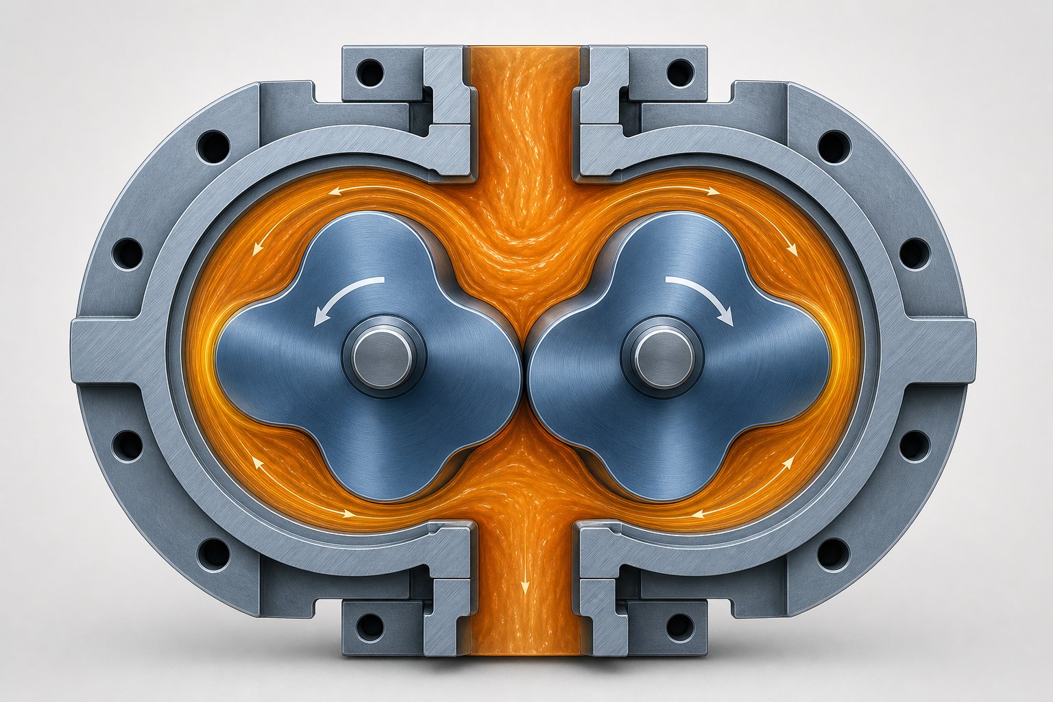
Picture two intermeshing screws rotating in the same direction inside a figure-eight barrel bore. Each disc on one shaft is shaped so that its lobes perfectly sweep the channels of the neighboring shaft's disc. This is the essence of the Erdmenger profile, first patented by Rudolf Erdmenger in 1957 (U.S. Patent No. 2,814,472). The cross-sectional shape of each disc is derived from conjugate profile geometry — a mathematical relationship ensuring that every point on one element's surface has a matching wipe point on its partner.
Why does this matter on your production floor? Self-wiping action prevents material from stagnating in dead zones between the screws. Stagnant polymer degrades, discolors, and eventually contaminates your product stream. The Erdmenger profile eliminates those pockets, giving kneading blocks twin screw extruder designs their characteristic resistance to material buildup and thermal degradation.
Two primary disc cross-sections dominate modern screw design: bi-lobal (double-flighted) and tri-lobal (triple-flighted) profiles. The choice between them shapes everything from free volume to shear intensity. Here's how they compare:
| Attribute | Bi-Lobal (Double-Flighted) | Tri-Lobal (Triple-Flighted) |
|---|---|---|
| Number of Lobes | 2 | 3 |
| Free Volume | Higher — deeper channels provide more material capacity | Lower — shallower channels reduce available volume |
| Shear Intensity | Moderate — fewer tip passes per revolution | Higher — more tip passes generate additional shear events |
| Self-Wiping Efficiency | Good — two contact arcs per rotation | Excellent — three contact arcs improve surface renewal |
| Typical Application Suitability | Standard compounding, filled systems, high-throughput processes | High-shear applications, reactive extrusion, small-diameter extruders |
Most co-rotating twin screw extruders — including platforms from KraussMaffei and other major OEMs — use bi-lobal geometry as the standard. Tri-lobal designs appear in specialized situations where intensified shear per revolution is needed, though they sacrifice some volumetric throughput capacity in the process. If you're sourcing kneading blocks for KraussMaffei or similar equipment, you'll almost always be working with bi-lobal elements unless your application specifically demands otherwise.
How Disc Geometry Translates to Mixing Action
Imagine squeezing toothpaste between your thumb and a flat surface. The paste is forced outward through the narrowing gap, experiencing intense elongational and shear stress in the process. That's essentially what happens inside each kneading block — material is squeezed through two critical narrow gaps with every shaft rotation.
The first gap is the tip clearance: the space between the outermost edge of each disc lobe and the barrel wall. The second is the intermesh gap: the clearance between the lobes of the two meshing discs. As the screws rotate, material is repeatedly dragged into these converging zones, stretched thin, and released — a squeeze-flow mechanism that delivers the high stress needed for dispersive mixing. Each pass through the gap breaks down agglomerates, ruptures immiscible droplets, and refines particle distribution.
The intensity of this squeeze-flow depends heavily on the screw's OD/ID ratio — the relationship between the outer diameter (the disc tip) and the inner diameter (the screw root). A larger OD/ID ratio means deeper channels and a greater difference between the tip speed and root speed, which increases the maximum shear rate the element can generate. This ratio is fixed by the extruder platform, so it's a constraint you design around rather than a variable you adjust. A higher ratio also means more free volume, affecting kneading block pitch selection and how aggressively you can configure the mixing zone without flooding or starving the element.
With multiple terms now in play, here's a concise reference glossary that ties them together:
- Stagger Angle: The angular offset between consecutive discs within a single kneading block element. Controls forward conveying tendency, residence time, and shear intensity.
- Disc Width: The axial thickness of each individual disc. Wider discs intensify dispersive mixing; narrower discs increase the number of angular transitions per unit length, favoring distributive mixing.
- Tip Clearance: The radial gap between the disc tip and the barrel wall. Smaller clearances increase shear stress on the material passing through.
- Lobe Geometry: The cross-sectional profile of each disc — bi-lobal or tri-lobal — which determines the number of shear events per revolution and the available free volume.
- OD/ID Ratio: The ratio of the screw's outer diameter to its inner (root) diameter. Defines the channel depth and maximum achievable shear rate for a given extruder platform.
These five parameters interact with each other in ways that aren't always intuitive. The stagger angle, in particular, deserves its own deep examination — because it's the single variable that processors adjust most frequently and misunderstand most often.
Stagger Angle Reference Guide for Every Kneading Block Configuration
Of all the variables you can change on a kneading block, the stagger angle is the one that has the most immediate and dramatic impact on process behavior. It's also the one most frequently chosen based on habit rather than logic. A technician reaches for a 60° element because "that's what we always use," while a 45° or 90° block might be exactly what the application demands. This section breaks down every standard angle, ranks them side by side, and — more importantly — gives you a decision framework for picking the right one based on your specific process goal.
Stagger Angle Definitions from 30° to 90°
The stagger angle is simply the angular offset between consecutive discs within a single kneading block element. When you look down the shaft axis of a five-disc block, each disc is rotated by this angle relative to the one before it. A small angle — say 30° — means the discs are nearly aligned, creating a geometry close to a conveying element. A large angle — 90° — means every disc sits perpendicular to its neighbor, producing maximum flow disruption and zero forward pumping.
That angular offset controls a fundamental balance inside the barrel: forward conveying thrust versus shear resistance. Small offsets preserve most of the forward driving force, moving material quickly downstream with gentle mixing and minimal heat generation. Large offsets slash that driving force, trapping material in the kneading zone longer and subjecting it to progressively more intense shear and frictional heating. At 90°, the element loses all axial conveying ability entirely — material can only pass through when pushed by upstream pressure.
The following table consolidates the performance characteristics of all four standard stagger angles in one place. Rather than hunting through fragmented sources, you'll find the complete comparison here:
| Attribute | 30° Stagger | 45° Stagger | 60° Stagger | 90° Stagger |
|---|---|---|---|---|
| Forward Conveying Capacity | High — geometry close to conveying elements | Moderate — stable forward transport maintained | Low — conveying drops significantly | Zero — no axial conveying; material passes only via upstream pressure |
| Shear Intensity | Low — gentle, distributive shear dominates | Moderate — balanced shear sufficient for general homogenization | High — strong dispersive stretching and breaking action | Very High — maximum radial shear force, peak stress on material |
| Residence Time Effect | Minimal increase — fast material passage | Slight increase — material dwells moderately longer | Notable increase — extended dwell in kneading zone | Maximum increase — material is fully retained until pushed through |
| Backpressure Generation | Low | Low to Moderate | Moderate to High | High — acts as a flow restriction or melt seal |
| Melt Temperature Rise | Minimal — fast flow reduces frictional heating | Moderate — manageable for most general-purpose resins | Significant — extended residence converts mechanical energy to heat | Peak — extreme frictional heat generation; highest degradation risk |
| Best-Fit Applications | Heat-sensitive polymers; initial softening in the melting zone; gentle distributive blending | General-purpose plastics; primary melting section; preliminary homogenization | Polymer alloys with viscosity mismatch; mineral filler dispersion (CaCO3, talc, TiO2); agglomerate breaking | Melt seal before vent ports; final dispersion of glass fiber and heavy fillers; extreme homogenization at end of mixing sections |
The performance rankings across these four angles follow a consistent hierarchy. Axial conveying capacity runs 30° > 45° > 60° > 90°, while shear intensity and energy dissipation both run in the exact opposite order: 90° > 60° > 45° > 30°. These aren't subtle differences — they represent fundamentally different processing behaviors from elements that look similar on a shelf.
Choosing the Right Angle for Your Process Goal
Knowing what each angle does is useful. Knowing why you'd choose one over another is where real process improvement happens. Instead of defaulting to a familiar configuration, consider the decision as a series of trade-offs anchored to your material's properties and your quality targets.
Start with thermal sensitivity. If the polymer degrades, discolors, or loses molecular weight within a narrow temperature window — think PVC, certain biopolymers, or heat-sensitive pigment systems — your primary constraint is melt temperature rise. In these cases, a 30° kneading block is the safest starting point. It provides mild shear with strong forward conveying, minimizing the time material spends under mechanical stress and the frictional heat that comes with it. You sacrifice mixing intensity, but you preserve the material. For slightly less sensitive formulations, a 45° block offers a meaningful step up in homogenization while keeping temperature rise manageable.
Then evaluate mixing demand. If your process requires breaking hard agglomerates — calcium carbonate clusters, carbon black bundles, or poorly wetted glass fibers — gentle distributive mixing won't cut it. You need the high-stress squeeze-flow that only 60° or 90° stagger angles deliver. A 60° element is often the workhorse here: it provides powerful dispersive shear while still retaining some forward conveying capacity, making it the most common general-purpose choice for filled polymer compounding and polymer alloy blending. Numerical simulation studies confirm that increasing the stagger angle directly increases mixing degree and particle dispersion, with higher offsets promoting greater backflow between adjacent discs and broader residence time distributions.
Reserve 90° for specific functional roles. A backpressure kneading block set at 90° offset is not a general mixing element — it's a process tool with a very specific purpose. Because it generates zero forward conveying, it forces a complete fill of the upstream barrel section, creating an effective melt seal. This makes it indispensable before devolatilization vent ports, where you need a pressure drop immediately downstream but a tight seal upstream to prevent gas from traveling backward. It also serves as a final homogenization barrier in mixing sections where every last agglomerate must be broken before the melt exits to the die. The trade-off is severe: energy dissipation is at its peak, and overlong 90° segments easily trigger localized molecular degradation, discoloration, or scorching.
Consider left kneading block elements for extreme cases. Reverse (left-handed) configurations push material backward against the flow direction, creating even more intense backpressure and local fill than a 90° neutral element. They're covered in depth in the next section, but the decision logic ties directly to the stagger angle framework: if a 90° block at the end of your mixing zone still doesn't deliver adequate dispersion, a reverse element can force additional residence time and shear. This approach is common in kneading blocks for Wenger and Baker Perkins food and feed extruders, where breaking down fibrous or highly viscous raw materials demands aggressive mechanical input.
The underlying principle connecting all of these choices is a single trade-off:
Higher stagger angles increase both mixing intensity and melt temperature. The optimal angle is always determined by the narrowest constraint — either the material's thermal degradation limit or the minimum mixing intensity required for acceptable product quality.
Practically, most screw profiles don't rely on a single stagger angle. They combine multiple angles in sequence — a 30° or 45° block for initial plasticization, followed by 60° elements for primary mixing, with a 90° block as a melt seal or final barrier. The art of screw design lies in sequencing these angles to deliver just enough shear at each stage without overshooting the material's thermal window at any point along the barrel.
Stagger angle, however, is only one dimension of the picture. A 60° block with wide discs behaves very differently from a 60° block with narrow discs — and the number of discs in each element introduces yet another layer of interaction that reshapes conveying, fill level, and temperature rise in ways the angle alone cannot predict.
Forward, Neutral, and Reverse Kneading Block Configurations
Stagger angle tells you how aggressively each disc offsets from its neighbor — but there's a second, equally critical variable hiding in plain sight: the direction of that offset. Two kneading blocks can share the same 45° stagger angle and identical disc geometry yet produce completely opposite effects on material flow, simply because one is arranged in a forward-pumping spiral and the other reverses that spiral to push material upstream. Understanding this directional distinction is essential for controlling pressure profiles, fill levels, and residence time throughout your screw.
Forward Kneading Blocks and Their Conveying Action
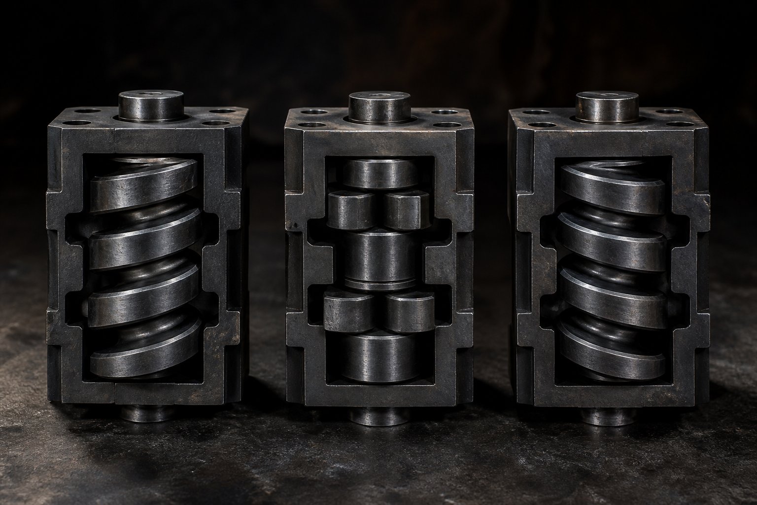
A forward kneading block has its discs offset in the same rotational direction as standard conveying elements — typically right-handed on co-rotating twin screw extruders. This means each disc nudges the melt downstream as the shaft turns, combining mixing action with positive forward transport. The result is a dual-function element that simultaneously shears the polymer and moves it toward the die.
You'll find forward-configured blocks in virtually every screw profile because they deliver exactly this balance. As Kenneth Russell explains, a 30° forward element pulls feed material into the melting zone with minimal backflow, while a 60° forward element provides stronger work input with reduced but still positive conveying. The lower the stagger angle, the more the element behaves like a conveying screw; the higher the angle (up to just below 90°), the more shear dominates and forward transport diminishes. This sliding scale gives processors a finely tunable tool: pick a low-angle forward block for gentle plasticization of heat-sensitive resins, or step up to a higher-angle forward block for more aggressive melting and mixing — all without sacrificing the basic downstream flow direction.
Neutral Kneading Blocks at 90° Offset
At exactly 90°, something fundamental changes. The disc-to-disc offset no longer creates any net axial pumping in either direction. Material enters the element and simply stays there, being sheared and folded, until upstream pressure physically pushes it through. This makes a 90° neutral block a powerful restrictive element — it forces the upstream barrel section to fill completely, raises local pressure, and extends the time material spends under mechanical stress.
That restriction is precisely why neutral elements are indispensable before devolatilization vent ports. A fully filled section of melt upstream of the vent creates an effective melt seal, preventing vapor from traveling backward through the barrel while allowing volatile gases to escape downstream through the vent opening. Without this seal, vacuum applied at the vent would pull air back through the feed zone rather than stripping volatiles from the melt.
The trade-off is substantial energy input. Because no conveying action carries material away, every bit of shear work converts to heat within a concentrated zone. On thermally robust polymers, this is manageable. On heat-sensitive formulations, the residence time increase can push melt temperatures past safe limits in a hurry.
Reverse Kneading Blocks and Back Pressure Generation
Reverse — or left-handed — kneading blocks take the restriction concept a step further. Instead of passively holding material in place, they actively pump it backward against the process flow direction. This creates intense local backpressure, dramatically increasing the fill level, shear stress, and residence time in the upstream kneading zone. The effect is far more aggressive than a 90° neutral block: material is essentially trapped between the forward-pumping upstream elements and the backward-pumping reverse element, creating a high-energy mixing region where even stubborn agglomerates and high-viscosity phases are forced to break down.
A backward kneading block for Baker Perkins or a backward kneading block for Wenger food and feed extruders serves the same fundamental purpose as one on a plastics compounder — it forces additional mechanical work into materials that resist mixing under gentler conditions. On food extruders, fibrous proteins and starchy doughs may require this level of restriction to achieve full transformation. On plastics lines, a backward pumping kneading block for Baker Perkins or backward pumping kneading block for Wenger platforms targets hard mineral fillers, poorly wetted glass fibers, or immiscible polymer blends that demand extreme dispersive stress.
Here's a practical summary of where each configuration fits in a real screw profile:
- Forward kneading blocks: Primary melting and plasticization zones; initial mixing after feed entry; distributive blending of color concentrates and low-loading additives; any section where mixing must occur without choking material flow.
- Neutral (90°) kneading blocks: Melt seals upstream of atmospheric or vacuum vent ports; final homogenization barriers at the end of intensive mixing zones; restriction points to increase fill level and residence time in specific barrel sections.
- Reverse kneading blocks: Melt seals requiring stronger backpressure than 90° blocks alone; intensive dispersive mixing of hard-to-break fillers (glass fiber, carbon black, mineral clusters); high-viscosity polymer alloys needing extreme shear for phase breakup; secondary mixing zones where side-fed additives must be fully incorporated under challenging conditions.
However, reverse elements demand respect. Overusing them — stacking multiple left-handed blocks or placing them where material is not yet fully molten — invites serious problems. Torque spikes become a real risk as the motor fights to push material past an aggressive restriction. Localized overheating follows, since the mechanical energy trapped in the backpressure zone converts almost entirely to heat. And if the polymer's degradation temperature is exceeded, you'll see discoloration, molecular weight loss, or outright charring at the die. A good rule of thumb from experienced screw designers: keep the length of any reverse element shorter than the screw diameter to prevent excessive pressure peaks and material damage.
Direction and stagger angle together define what a kneading block does to the material flow. But how hard it works the material at any given angle and direction depends on a third factor that interacts with both: the width of each individual disc and the total number of discs stacked in the element.
Disc Width and Parameter Interactions That Shape Mixing
Two kneading blocks can share identical stagger angles and directional configurations yet deliver dramatically different results on your extrudate. The hidden variable? Disc width — and how it interacts with the number of discs and the stagger angle to create combined effects that none of these parameters can produce alone.
How Disc Width Affects Shear and Residence Time
Think of each disc in a kneading block as an individual shear event. When the melt passes over a disc's lobe tip, it gets squeezed through the narrow gap between that tip and the barrel wall. A wider disc extends the length of that squeeze zone, holding the material under high stress for a longer stretch along the screw axis. The result is stronger dispersive mixing — more energy input per disc, more force applied to break agglomerates, and greater peak temperatures within the element. This is exactly what you want when dispersing stubborn mineral fillers like calcium carbonate or talc into a polymer matrix.
Narrow discs flip the priority. Each individual disc still creates a shear event, but it's shorter and less intense. The advantage is that you can fit more discs — and therefore more angular transitions — into the same overall element length. Every angular transition forces the melt to change direction, reorienting material packets and redistributing minor components across the cross section. That's distributive mixing in action: spatial rearrangement rather than brute-force particle breakup.
Practical guidance follows directly from this distinction:
- Narrow discs are preferred for color masterbatch production, distributive blending of low-loading additives, and applications where homogeneity of distribution matters more than agglomerate size reduction.
- Wide discs suit filler dispersion, breaking agglomerates in heavily loaded mineral compounds, and applications demanding high-stress squeeze-flow to fracture hard particles.
Material properties should guide your selection further. For thermally sensitive polymers — PVC, certain biodegradable resins, or formulations with heat-sensitive pigments — narrow discs combined with low stagger angles (30° or 45°) limit peak temperatures by reducing the duration and intensity of each shear event. Wider discs at higher angles push significantly more mechanical energy into the melt, which is productive on robust polyolefins but destructive on materials with tight thermal processing windows.
Combined Parameter Effects and Interaction Logic
Here's where it gets interesting — and where most technical resources stop short. Disc width, stagger angle, and the number of discs don't act independently. They interact in a three-way relationship that fundamentally changes the element's behavior.
Imagine two kneading blocks of roughly the same overall length. One has five narrow discs at 30° offset. The other has three wide discs at 60° offset. Despite occupying similar space on the shaft, they behave in fundamentally different ways. The five-disc/narrow/30° block produces many angular transitions (four total offset steps) with gentle shear at each step and strong forward conveying — making it ideal for distributive blending. The three-disc/wide/60° block generates fewer transitions (just two offset steps) but each one delivers intense, prolonged shear with reduced forward pumping — targeting dispersive filler breakup instead.
Research from Paderborn University quantifies this interaction clearly. In 3D CFD simulations comparing a short (12 mm) five-disc 90° kneading block against a longer (24 mm) five-disc 90° block on a ZSK25 extruder, the wider-disc KB24 achieved an MQ distributive mixing index of approximately 0.92 at 400 rpm, while the narrower-disc KB12 lagged behind at roughly 1.34. The wider discs provided enough sustained flow disruption to redistribute particles far more effectively, despite having the same number of discs and the same stagger angle. Meanwhile, a separate CFD study on highly filled graphite compounds found that two narrow 90° kneading blocks matched the distributive mixing coefficient (0.75) of three narrow 45° blocks — demonstrating that a higher stagger angle can compensate for fewer elements when narrow discs are used.
The underlying principle is straightforward: the total number of angular transitions drives distributive mixing, while individual disc width and stagger angle drive dispersive mixing. The table below illustrates how three representative combinations stack up:
| Configuration | Dispersive Mixing | Distributive Mixing | Forward Conveying | Fill Level | Temperature Rise |
|---|---|---|---|---|---|
| Narrow discs / 30° / 5 discs | Low — short, gentle shear events | High — four angular transitions redistribute material repeatedly | Strong — geometry close to conveying element | Low — material moves through quickly | Minimal — low energy input per disc |
| Wide discs / 60° / 3 discs | High — prolonged squeeze-flow at each disc | Moderate — only two transitions limit redistribution | Low — high offset reduces pumping action | Moderate to High — restricted flow increases local fill | Significant — extended shear converts to heat |
| Wide discs / 90° / 3 discs | Very High — maximum shear stress at each disc | Moderate — two transitions, but full fill improves cross-channel movement | Zero — no axial pumping; material held until pushed through | High — complete fill upstream of element | Peak — highest risk of thermal degradation |
This table reveals why a one-size-fits-all kneading block doesn't exist. Every application demands a specific balance point between these competing effects, and the only way to hit that balance is by adjusting disc width, angle, and disc count together — not in isolation. Any reliable kneading block supplier or kneading block factory should be able to provide elements across the full range of these configurations, because locking into a single standard combination means leaving process performance on the table.
Understanding how these parameters interact gives you the engineering foundation. The next logical step is translating that foundation into application-specific decisions — matching real-world materials and process goals to the configuration that delivers the best result without exceeding the material's limits.
Application-Driven Kneading Block Selection Across Industries
You understand the geometry. You know how stagger angles, disc widths, and directional configurations shape mixing behavior. But here's the question that matters most on a production floor: which combination should you actually use for your material and your process? The answer depends less on textbook theory and more on the specific demands your application places on the melt — demands that vary enormously between a mineral-filled polyolefin compound and a heat-sensitive color masterbatch.
Kneading Block Selection by Application Category
Different compounding applications impose fundamentally different constraints on the kneading zone. A configuration optimized for pigment distribution would destroy fiber length in a glass-reinforced compound. An aggressive setup designed for mineral dispersion would scorch a PVC formulation. The key is matching the mixing intensity and residence time profile to what the material actually needs — nothing more, nothing less.
Here are the recommended configurations for the most common application categories, drawn from established compounding practice and twin screw design principles:
- Filled polymer compounding (CaCO3, talc, TiO2, BaSO4): High-shear wide discs at 60° stagger form the backbone of most mineral filler dispersion zones. The extended squeeze-flow per disc breaks down agglomerates effectively, while the 60° offset provides enough residence time for stress to act on hard particle clusters. For highly loaded systems above 50% filler, a short reverse element or 90° block at the end of the kneading zone ensures complete wetting and breakup before the melt exits to conveying sections. A durable backward kneading block for KraussMaffei or similar OEM platforms handles this duty reliably in heavy-duty compounding lines.
- Color masterbatch production: Narrow discs at 30° to 45° offset deliver the distributive mixing that pigment dispersion demands — many angular transitions redistribute pigment particles across the melt cross section without generating the excessive heat that degrades organic pigments or shifts color values. The priority here is homogeneity of spatial distribution, not brute-force agglomerate breakup. If certain inorganic pigments (carbon black, iron oxides) require additional dispersive stress, a short 60° wide-disc section can be added, but it should remain brief to avoid overheating.
- Reactive extrusion (grafting, coupling, chain extension): Controlled residence time is the critical variable. Reactions need enough time under shear to reach target conversion, but excess residence triggers side reactions, crosslinking, or degradation. Neutral 90° blocks placed strategically create defined high-fill zones where reactant concentration and mixing intensity peak — ideal for maleic anhydride grafting or silane crosslinking. Toothed mixing elements downstream of the reaction zone distribute the product without adding unnecessary thermal history.
- Devolatilization (monomer stripping, moisture removal): A 90° melt seal block placed immediately upstream of the vacuum vent port is essential. It creates a fully filled, pressurized zone that prevents vapor from migrating backward through the barrel. Downstream of the vent, deep-flight conveying elements with no kneading blocks maximize free surface area for volatile escape. Getting this wrong — using a forward block instead of a neutral or reverse seal — results in melt flooding the vent port or inadequate volatile removal.
- Recycling applications (post-consumer PE, PP, PET): Variable feedstock quality defines this category. Contamination levels, moisture content, viscosity swings, and mixed polymer fractions all fluctuate batch to batch. Moderate shear configurations — 45° to 60° forward blocks with medium-width discs — provide enough mixing to homogenize inconsistent feed without the aggressive energy input that would degrade already-stressed polymer chains. A durable backward kneading block for Wenger or similar food-grade extruder platforms follows the same logic when processing recycled starch-based or biopolymer feedstocks, where thermal sensitivity compounds the variability challenge.
Matching Configuration to Material Properties
Behind every application category sits a set of material properties that actually dictates which kneading block parameters will work and which will cause problems. Three properties matter most: melt viscosity, filler loading, and thermal sensitivity. Each one pulls the optimal configuration in a different direction — and real-world formulations almost always involve trade-offs between them.
Melt viscosity determines how much shear stress the material generates internally as it flows through the kneading zone. High-viscosity engineering polymers like PA66, PC, and PEEK need higher stagger angles — 60° or above — to generate sufficient stress for melting and homogenization. The catch is that high viscosity also means high viscous dissipation: more of the mechanical energy converts to heat inside the melt itself, raising temperatures faster than with low-viscosity resins at the same screw speed. The practical response is to use higher angles but keep the kneading zone shorter, or to increase barrel cooling in the mixing section. As industry guidelines for screw element selection emphasize, spreading kneading blocks across multiple shorter zones separated by conveying elements prevents localized overheating while still delivering adequate total energy input.
Filler loading and particle hardness create a second axis of tension. Heavily filled compounds — 40% to 70% mineral content — demand strong dispersive mixing to break filler agglomerates and fully wet particle surfaces. Wide discs at high stagger angles deliver that stress. But abrasive fillers like glass fiber, silica, and wollastonite simultaneously accelerate wear on the kneading disc tips and barrel wall. The harder you push dispersion, the faster you consume your elements. This is where metallurgical selection becomes inseparable from geometric configuration: a cobalt-based backward kneading block for KraussMaffei platforms, for example, pairs aggressive mixing geometry with wear-resistant alloy construction to sustain performance under abrasive conditions far longer than standard nitrided tool steel.
Thermal sensitivity imposes the hardest constraint. Materials like plasticized PVC, EVOH, certain biopolymers (PLA, PHA), and formulations containing heat-sensitive flame retardants or organic pigments have narrow processing windows — sometimes as tight as 10° to 15°C between adequate melting and the onset of degradation. For these materials, the gentlest effective configuration is the only safe option: narrow discs, low stagger angles (30° or 45°), minimal or no reverse elements, and the shortest kneading zone that still achieves acceptable mixing. Every degree of additional shear intensity is a gamble against the degradation limit.
The optimal kneading block configuration is always a compromise between mixing adequacy and thermal-mechanical damage limits. No single geometry is universally "best" — the right choice is the one that delivers just enough mixing intensity to meet product specifications without exceeding the material's tolerance for heat and shear stress.
This compromise plays out differently in every plant and on every formulation. But the logic is consistent: identify your tightest constraint (thermal window, dispersion requirement, throughput target, or wear budget), then configure the kneading zone to satisfy that constraint first. Adjust all other parameters around it. That disciplined approach consistently outperforms the common alternative — copying a generic screw design and hoping it fits.
Selecting the right elements for each application is half the challenge. The other half — and one that's equally underappreciated — is deciding where along the screw those elements should sit. Placement within the overall barrel profile shapes whether your carefully chosen kneading blocks actually deliver their intended effect or work against the process flow.
Strategic Kneading Block Placement in the Screw Profile
You could have the perfect stagger angle, ideal disc width, and the exact right directional configuration — and still get poor results if those elements sit in the wrong position along the barrel. Placement determines whether your kneading block encounters material that's ready to be mixed or material that's barely begun to soften. Get the sequencing wrong, and you're either grinding solid pellets against hardened steel or gently folding a melt that needed aggressive work three barrel zones earlier.
Where to Place Kneading Blocks Along the Screw
Every barrel zone in a twin screw extruder has a specific job — feeding, melting, mixing, venting, metering — and kneading blocks must align with those jobs to function as intended. A kneading section positioned too early in the screw, before the polymer has absorbed enough thermal energy to soften, forces partially solid pellets through narrow disc gaps. The result? Excessive torque loads on the motor, accelerated wear on the disc tips, and an unstable process that surges as chunks of unmelted material periodically break through. On the other end, placing intensive mixing elements too close to the die leaves insufficient barrel length for conveying elements to rebuild the stable pressure needed for consistent output and dimensional control.
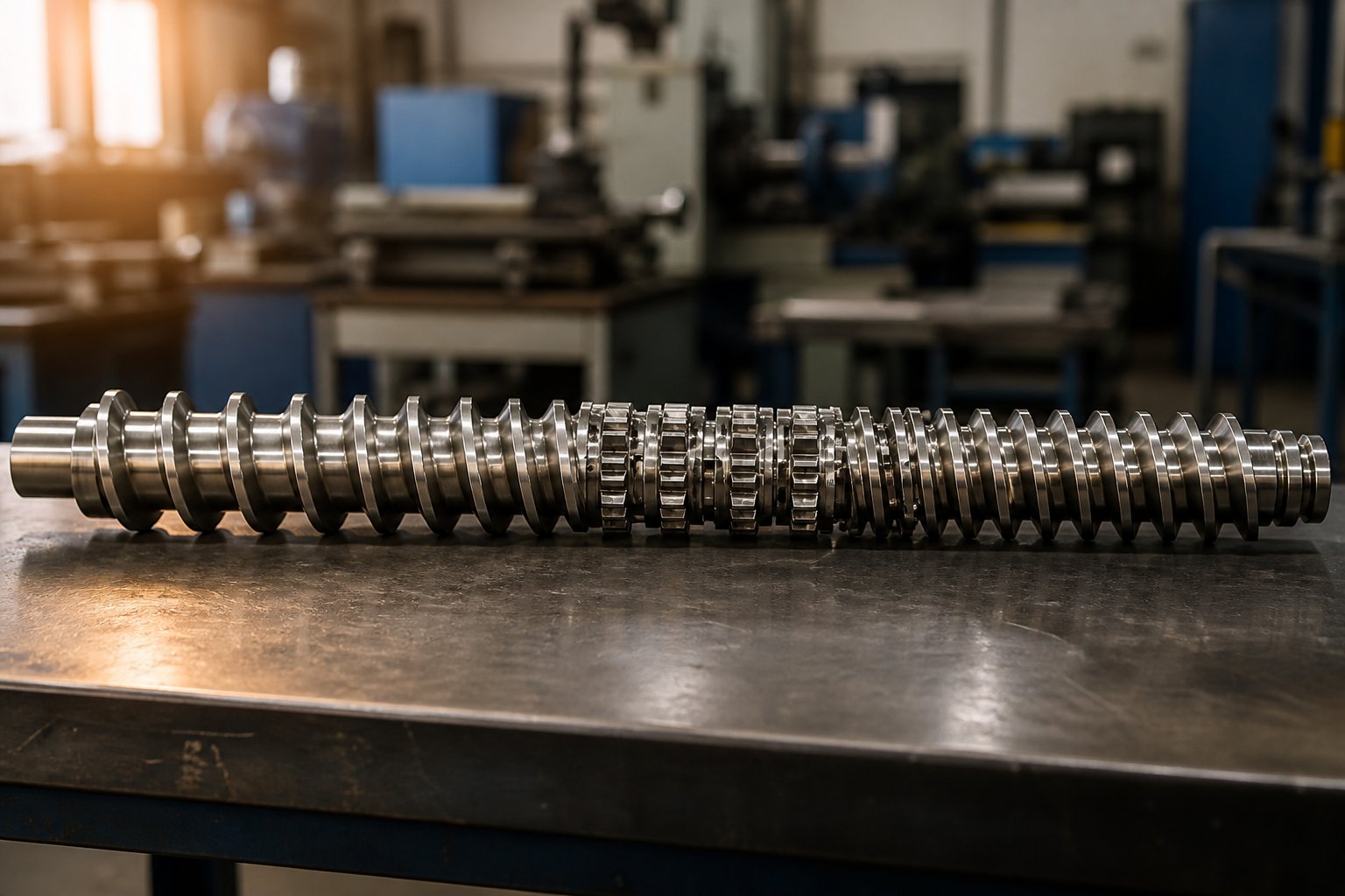
The typical screw profile for a co-rotating twin screw extruder follows a logical progression that mirrors how the material transforms as it moves from feed throat to die face:
- Feed zone: Large-pitch conveying elements grip incoming pellets or powder and push them forward with minimal compression. No kneading blocks belong here — the material isn't ready for shear, and aggressive elements would cause bridging and torque spikes.
- Melting and plasticization zone: Forward kneading blocks at moderate stagger angles (30° to 45°) begin the transition from solid to melt. These elements apply enough shear to initiate frictional heating and pellet deformation while maintaining strong forward conveying so material doesn't stall. The pitch of the upstream conveying elements typically tightens just before this zone to increase compression and ensure the kneading discs engage a consistent bed of material.
- Primary mixing zone: More intensive kneading blocks — 60° wide-disc elements for dispersive work or narrow-disc elements for distributive blending — handle the bulk of the mixing task. By this point, the polymer should be fully or nearly fully molten, meaning the kneading discs are working on a viscous fluid rather than fighting unmelted solids. This is where fillers, pigments, and additives get dispersed and distributed.
- Melt seal before vent ports: A 90° neutral block (or a short reverse element) creates a fully filled, pressurized section that prevents vapor migration upstream. This seal is non-negotiable for effective devolatilization — without it, vacuum applied at the vent pulls air backward through the barrel instead of stripping moisture or volatiles from the melt surface.
- Metering and pressurization zone: Conveying elements with progressively tighter pitch rebuild stable die pressure. Kneading blocks are typically absent from this final section, since the priority shifts entirely to smooth, consistent flow delivery.
This sequence isn't arbitrary. It mirrors the material's physical state at each position — solid granules at the inlet, a softening bed in the melting zone, a fully developed melt in the mixing section, and a pressurized, homogeneous stream at the die. Every kneading block placement decision should answer one question: is the material in the right state to benefit from what this element does?
Sequencing Logic for Multi-Zone Screw Profiles
Many compounding processes — especially those involving side-fed fillers, downstream liquid injection, or multiple devolatilization stages — require two or more separate kneading zones along the barrel. The logic is straightforward: the first kneading zone handles melting and initial homogenization of the base polymer, while the second (or third) zone provides targeted mixing after new components are introduced further downstream.
Consider a glass-fiber-reinforced polyamide compound. The base PA resin melts and homogenizes in the first kneading zone near barrel zones 3 through 5. Chopped glass fibers enter via a side stuffer at barrel zone 7. A second kneading zone immediately downstream — typically gentler than the first, using moderate-angle forward blocks to preserve fiber length — wets and distributes the fibers without excessive breakage. Separating these zones with conveying elements serves a critical purpose: it allows pressure to rebuild between kneading sections, prevents the fill level from dropping to the point where the downstream blocks run starved, and gives barrel cooling zones an opportunity to pull excess heat from the melt before it enters the next shear-intensive section.
The transition from kneading blocks back to conveying elements deserves particular attention. An abrupt shift from an aggressive 90° or reverse element directly into a large-pitch conveying screw can create a sudden pressure drop, momentarily starving the downstream barrel and causing output surging at the die. Experienced screw designers typically use a short intermediate conveying element with moderate pitch — bridging the pressure transition rather than letting it happen all at once.
If you're designing or modifying a screw profile and need a systematic approach, follow this framework for determining kneading block placement:
- Map the material's physical state along the barrel. Identify where the feedstock transitions from solid to partially molten to fully molten. Your first kneading zone should begin only after enough thermal energy has entered the material to soften it — typically after two to four barrel zones of conveying and compression.
- Identify every downstream addition point. Side feeders, liquid injection ports, and vent locations each define where new kneading zones may be needed or where they must be avoided. A kneading block placed directly at a side-feed opening will block filler entry; it belongs immediately downstream of that port instead.
- Assign a mixing objective to each kneading zone. Is the zone responsible for melting, dispersive filler breakup, distributive blending, or creating a melt seal? Each objective dictates the stagger angle, disc width, and directional configuration, as covered in the preceding sections.
- Insert conveying sections between kneading zones. These recovery zones rebuild pressure, manage fill level, and allow barrel temperature control to counteract shear-generated heat. Skipping this step — stacking kneading zones back to back without conveying relief — invites torque overloads and uncontrolled temperature rise.
- Place melt seals before every vent port. Use a 90° neutral or short reverse element to create a fully filled section upstream of each atmospheric or vacuum vent. Verify that the seal is long enough to hold pressure but short enough to avoid excessive energy input.
- Reserve the final barrel zones for pressure building. Tight-pitch conveying elements in the last two to three barrel sections stabilize die pressure and ensure consistent extrudate dimensions. Adding kneading blocks here risks destabilizing the output.
- Verify torque and temperature margins. After laying out the profile, check that the cumulative energy input from all kneading zones stays within the motor's torque capacity and the material's thermal window. If either limit is exceeded, reduce kneading zone length, lower stagger angles, or replace dispersive elements with milder distributive alternatives.
Any kneading blocks twin screw extruder manufacturer or kneading blocks twin screw extruder supplier should be able to provide the full range of element geometries — forward, neutral, and reverse configurations across all standard stagger angles and disc widths — so that your placement decisions aren't constrained by limited inventory. A well-stocked kneading blocks twin screw extruder factory will carry modular elements compatible with your specific OEM shaft spline, making it practical to experiment with placement variations without commissioning custom parts for every trial.
Placement and sequencing give you control over where mixing happens and in what order. But even a perfectly positioned screw profile can underperform — or fail outright — if the elements themselves aren't delivering the expected mixing intensity. That's where diagnostics come in: reading the symptoms your extrudate and process data are giving you, and tracing them back to specific kneading block causes.
Troubleshooting Common Kneading Block Problems
Your screw profile follows the textbook layout. The stagger angles match the application. The placement logic checks out. Yet the extrudate still shows problems — color streaks, undispersed filler specks, unexplained torque spikes, or barrel zones running hotter than any setpoint can control. When a well-designed profile underdelivers, the root cause almost always traces back to a mismatch between what the kneading block configuration promises on paper and what it actually does to the material under real operating conditions. The gap between theory and production floor reality is where troubleshooting lives.
Diagnosing Poor Dispersion and Inhomogeneous Output
Imagine pulling a strand from the die and finding tiny white specks scattered through a dark compound, or color swirls that refuse to disappear no matter how long you run the line. These visual defects are direct evidence that the kneading zone isn't finishing its job.
Underdispersed output — visible filler agglomerates, gel particles, pigment streaks, or unmelted polymer fragments — tells you that the material passed through the mixing zone without receiving enough shear stress or residence time to break down its components. The fixes work in escalating order of intensity:
- Increase the stagger angle (step from 45° to 60°, or from 60° to 90°) to raise shear stress per disc.
- Switch to wider discs to extend the squeeze-flow zone and intensify dispersive action.
- Add a short reverse element at the end of the kneading zone to increase local fill and residence time.
- Extend the overall kneading zone length by inserting additional forward kneading blocks before the existing ones.
Each step adds energy to the melt, so monitor melt temperature after every change. The goal is to reach adequate dispersion — not to maximize shear for its own sake.
Overdispersed or degraded output presents the opposite symptom set: discoloration (yellowing, browning, or darkening), reduced mechanical properties, brittleness, or a noticeable drop in melt viscosity that signals molecular weight loss. These signs mean the material spent too long under too much stress. The corrective direction reverses: reduce stagger angles, swap wide discs for narrow ones, remove reverse elements, or shorten the kneading zone entirely. As USEON's troubleshooting guidance emphasizes, the objective of screw configuration is not maximum shear — it's providing enough mixing to complete the required process without unnecessary energy input.
A subtler variant of inhomogeneity is inconsistent output quality that fluctuates between acceptable and defective strands within the same run. This often points to unstable fill levels in the kneading zone — the elements are cycling between fully engaged mixing and partially starved operation, typically caused by feed rate fluctuations or improper pressure transitions between conveying and kneading sections. Check feeder stability and verify that conveying elements upstream of the kneading zone maintain consistent material delivery before adjusting the blocks themselves.
Resolving High Torque, Overheating, and Barrel Wear
Process symptoms that show up on your control panel — torque alarms, barrel zone temperatures that refuse to come down despite active cooling, rising die pressure trends, or output rate fluctuations — each have specific kneading block causes that the following troubleshooting matrix maps out:
| Symptom | Probable Kneading Block Cause | Recommended Configuration Adjustment |
|---|---|---|
| Excessive torque or motor overload | Too many reverse elements or 90° blocks creating aggressive restriction; kneading zone positioned before material is fully molten | Replace reverse blocks with neutral (90°) elements; reduce stagger angles in the first kneading zone; shift kneading blocks downstream to allow more pre-melting |
| High melt temperature that won't respond to barrel cooling | Overly intensive kneading configuration generating more shear heat than the cooling system can extract; excessive total kneading zone length | Shorten the kneading zone; reduce stagger angles (e.g., 60° to 45°); switch from wide to narrow discs; insert conveying sections between kneading zones for heat removal |
| Accelerated barrel wear concentrated at kneading zones | Abrasive fillers (glass fiber, silica, mineral fillers) combined with tight tip clearances on standard-metallurgy elements | Upgrade to wear-resistant alloy kneading elements (cobalt-based or nickel-based); consider slightly opening tip clearance if product quality allows |
| Vent flow problems (melt flooding vent port or poor volatile removal) | Insufficient melt seal upstream of vent — forward kneading blocks used where a 90° or reverse block is needed | Replace the element immediately upstream of the vent port with a 90° neutral block or short reverse element to establish a proper melt seal |
| Surging or pulsating output at the die | Unstable fill level in the kneading zone caused by abrupt pressure transitions; starving downstream of aggressive restriction elements | Add intermediate-pitch conveying elements between kneading and metering zones; reduce reverse element length; verify feeder consistency |
A few of these symptoms deserve deeper explanation because they're the ones most frequently misdiagnosed on the production floor.
High torque is often the first alarm that fires when a screw profile is too aggressive. The instinct is to reduce screw speed, but that can worsen the problem by increasing fill level and residence time in the restriction zone. A more effective first step is evaluating the reverse elements in the profile. As covered in the directional configuration section, reverse kneading blocks actively pump material backward, creating enormous local pressure. If you're running multiple reverse blocks or placing them where the polymer is still partially solid, the motor fights against a restriction it can't overcome efficiently. Replacing one reverse block with a 90° neutral element — or shortening its length — often resolves the torque issue while preserving most of the mixing benefit.
Barrel wear concentrated specifically at the kneading zones is one of the clearest diagnostic signals you'll encounter. It tells you that the high-shear, high-fill region is grinding abrasive particles against the barrel wall and disc tips at rates that standard nitrided tool steel cannot sustain. This pattern appears most frequently in heavily filled compounds — 40% or more calcium carbonate, glass fiber, or talc — where the mineral particles act like sandpaper under the intense squeeze-flow conditions kneading discs create.
The metallurgical response depends on the wear mechanism. For abrasion-dominated applications, cobalt-based alloys (such as Stellite overlays) dramatically extend element life. A cobalt-based backward kneading block for Wenger food extruders or a nickel-based backward kneading block for KraussMaffei compounding lines represents this principle in action — matching the alloy to the specific wear environment the element faces. Corrosive compounds (acidic resins, halogenated flame retardants, reactive extrusion byproducts) demand nickel-based alloys instead, since corrosion resistance matters more than hardness in those environments.
When wear reaches the point where increased tip clearance is visible — or when product quality begins declining without any process parameter changes — replacement is the only reliable fix. Sourcing those replacement elements matters as much as the metallurgy itself. Dimensional precision, spline profile compatibility with your specific OEM shaft, and consistent heat treatment across batches all determine whether the new element performs like the original or introduces new problems. Specialized kneading block suppliers like NANHAIYA focus specifically on modular twin screw extruder segments — kneading blocks, conveying elements, and mixing elements — built to match major OEM platforms including KraussMaffei, Wenger, Baker Perkins, and others. That kind of dedicated focus on segment screw manufacturing tends to deliver tighter tolerances and more reliable metallurgical consistency than generic aftermarket sources, particularly for wear-critical elements in compounding and recycling extruders.
Troubleshooting, at its core, is pattern recognition: match the symptom to the cause, then adjust one variable at a time. Resist the temptation to change multiple kneading block parameters simultaneously — doing so makes it impossible to isolate which adjustment actually solved the problem. Document what you change and what effect it produces. Over time, that log becomes the most valuable screw design resource in your plant.
Solving an immediate process problem is essential, but it's equally important to understand why kneading elements wear out in the first place and how your sourcing decisions affect long-term reliability. Wear mechanisms, metallurgical options, and supplier evaluation criteria all play directly into whether your next set of replacement elements delivers months of trouble-free running or repeats the same failure cycle.
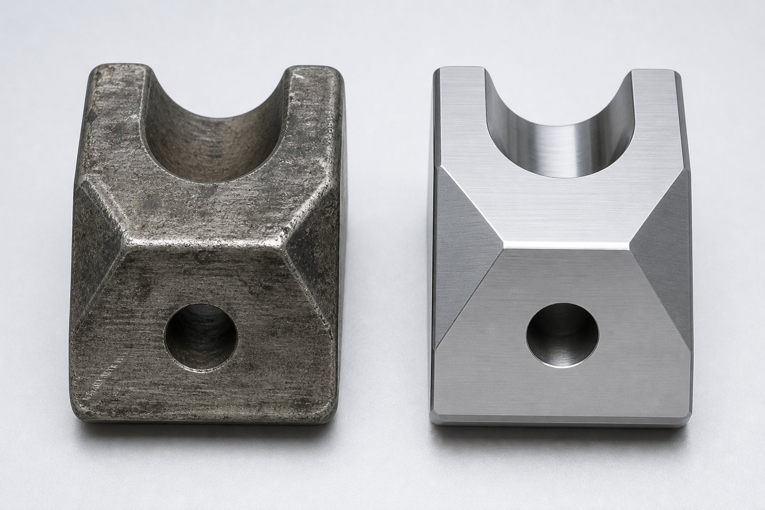
Kneading Block Wear, Metallurgy, and Sourcing Strategy
A perfectly configured screw profile solves today's process problem. But kneading blocks don't last forever — and the way they degrade over time determines how often you're pulling shafts, replacing elements, and absorbing unplanned downtime. For maintenance and procurement professionals, understanding the wear mechanisms at work inside each mixing zone is just as important as understanding the geometry itself. It's also the foundation for making smarter sourcing decisions that lower your true cost per kilogram of output.
Wear Mechanisms and Material Considerations
Three distinct wear modes attack kneading elements during operation, and most real-world applications involve a combination of all three acting simultaneously.
Adhesive wear occurs when polymer melt under high pressure creates metal-to-metal contact between the disc tips and the barrel wall. Under the intense squeeze-flow conditions inside a kneading zone, thin melt films can momentarily rupture, allowing direct surface contact that transfers microscopic metal particles from one surface to the other. This mode dominates in unfilled or lightly filled polymer processing where no hard particles are present, and it accelerates at higher screw speeds and tighter tip clearances.
Abrasive wear is the primary concern for any compounder running mineral fillers. Calcium carbonate, glass fiber, talc, silica, wollastonite — these particles act like fine sandpaper as they're forced through the narrow gaps between disc lobes and barrel bore. The harder and sharper the filler particles (measured on the Mohs hardness scale), the faster they erode element surfaces. As noted in industry wear data, standard tool steel elements in compounds loaded above 40% hard mineral filler can wear out in as few as 500 to 1,000 operating hours — a replacement frequency that quickly becomes the dominant cost driver for the entire compounding line.
Corrosive wear targets the element surface chemistry rather than its hardness. Reactive extrusion byproducts, acidic decomposition gases from flame retardants, moisture in hygroscopic resins, and halogenated compounds all chemically attack the metal surface, weakening it and accelerating mechanical wear. PVC processing is a classic example: hydrochloric acid released during thermal degradation aggressively corrodes standard steel alloys, demanding corrosion-resistant metallurgy regardless of filler loading.
Matching the right alloy to the dominant wear mode is the single most impactful decision you can make for element longevity:
- Nitrided tool steel — the standard baseline for general-purpose compounding of unfilled or lightly filled polymers. Adequate hardness (58-62 HRC) at reasonable cost, but limited life in abrasive or corrosive environments.
- Cobalt-based alloys (e.g., Stellite) — engineered for high-abrasion environments. These alloys maintain hardness at elevated temperatures and resist the gouging action of glass fiber, mineral fillers, and carbon black far longer than nitrided steel. Ideal for heavily filled polyolefin and engineering polymer compounds.
- Nickel-based alloys (e.g., Hastelloy-type) — prioritize corrosion resistance over pure abrasion hardness. The right choice for fluoropolymer processing, PVC compounding, and reactive extrusion involving acidic or halogenated chemistries where chemical attack is the primary failure mode.
Knowing when to replace worn elements before they compromise product quality is equally critical. Watch for these indicators that signal replacement is overdue:
- Increased tip clearance — measurable with feeler gauges during shaft pulls. Even a 0.1 mm increase beyond specification reduces shear stress and dispersive mixing effectiveness.
- Visible scoring or galling on disc lobe surfaces, indicating adhesive or abrasive material removal that will only accelerate.
- Dimensional out-of-tolerance measurements on the disc OD or spline bore, signaling that the element no longer maintains proper intermesh geometry.
- Declining product quality — increasing agglomerate counts, color inconsistency, or rising filter pressure values — without any change in process parameters, which points to reduced mixing capability from worn elements.
Sourcing Quality Kneading Block Elements
Recognizing that an element needs replacement is straightforward. Finding a supplier that delivers the right geometry, the right metallurgy, and the right dimensional precision — consistently, across repeat orders — is where procurement decisions get more complex. Whether you're sourcing wholesale kneading block elements for a scheduled rebuild or urgently replacing a single worn segment mid-campaign, the evaluation criteria remain the same.
Four factors separate reliable suppliers from risky ones: dimensional precision (tight tolerances on OD, bore, and disc thickness ensure proper intermesh and tip clearance), metallurgical consistency (uniform hardness and alloy composition across every element in a batch), OEM shaft spline compatibility (elements must mate perfectly with the shaft profiles used by your specific extruder manufacturer — KraussMaffei, Wenger, Baker Perkins, Coperion, Leistritz, and others), and range of available configurations (a supplier limited to a few standard angles and disc widths forces you to compromise your screw design around their inventory rather than your process needs).
The table below compares the three primary sourcing channels against these evaluation criteria, giving procurement teams a structured framework for vendor selection:
| Sourcing Channel | Dimensional Precision | Metallurgical Range | OEM Compatibility | Configuration Breadth | Cost Position | Lead Time |
|---|---|---|---|---|---|---|
| Specialized segment manufacturer (e.g., NANHAIYA) | High — dedicated tooling and QC for modular screw segments | Full range: nitrided steel, cobalt-based, nickel-based alloys | Broad — engineered to fit major OEM platforms including KraussMaffei, Wenger, Baker Perkins, and others | Comprehensive: all standard stagger angles, disc widths, forward/neutral/reverse configurations | Competitive — manufacturing scale in segment screw production reduces per-unit cost | Moderate — stock programs for common sizes; custom builds on order |
| OEM direct sourcing | High — original specifications guaranteed | Limited to OEM-standard grades; specialty alloys may require extended lead times | Guaranteed — elements designed for the specific machine | Full for that OEM's platform only | Premium — OEM margins built into pricing | Often long — OEM supply chains prioritize new machine builds |
| Generic aftermarket suppliers | Variable — quality depends heavily on the individual manufacturer's capabilities | Often limited to standard tool steel; premium alloys may be unavailable or inconsistent | Verify carefully — dimensional compatibility is not always guaranteed across all OEM shafts | Narrow — typically only high-volume standard configurations | Lowest — but hidden costs from poor fit or premature wear can offset savings | Short for stock items; unpredictable for non-standard requests |
For compounders and recyclers running kneading blocks twin screw extruder platforms from multiple OEMs — a common reality in plants that have expanded equipment over decades — a supplier like NANHAIYA that engineers elements for cross-platform compatibility eliminates the need to maintain separate vendor relationships for each machine. Their focus on twin screw extruder segments — kneading blocks, conveying elements, and mixing elements for compounding, pelletizing, masterbatch, and recycling applications — means the wholesale kneading blocks twin screw extruder buyer gets access to the full configuration range without the premium pricing of OEM-direct channels.
When evaluating any kneading blocks twin screw extruder for sale from a new supplier, request a first-article dimensional inspection report and a metallurgical certification for the specific alloy grade. Fit-check the first delivery on your shaft before committing to a bulk order. And keep records of element service life by position on the screw — that data becomes your most powerful tool for optimizing both your screw design and your sourcing strategy over time. The compounders who track hours-to-replacement by element position consistently make better purchasing decisions than those who simply reorder the same parts on a calendar schedule.
Whether you're sourcing kneading blocks twin screw extruder China manufacturers or evaluating local aftermarket options, the decision framework stays the same: prioritize dimensional accuracy and metallurgical reliability first, then optimize on cost and lead time. The cheapest element that wears out in half the time — or doesn't fit the shaft properly — is never actually cheap.
Frequently Asked Questions About Kneading Blocks
1. What is the function of a kneading block in a twin screw extruder?
A kneading block serves as the primary mixing element on a co-rotating twin screw extruder. It consists of elliptical discs mounted at staggered angles on a spline shaft. As the screws rotate, material is forced through narrow gaps between disc tips and the barrel wall, generating intense shear and elongational stress. This squeeze-flow action performs two essential tasks: dispersive mixing, which breaks down filler agglomerates and immiscible polymer droplets, and distributive mixing, which redistributes all components evenly throughout the melt. No other screw element exerts as much control over specific mechanical energy input, melt temperature, and final product homogeneity. Suppliers like NANHAIYA (nhyscrew.com) manufacture modular kneading block segments in all standard configurations to fit major OEM extruder platforms.
2. How do I choose the right kneading block stagger angle for my application?
Stagger angle selection depends on two competing constraints: the minimum mixing intensity your product requires and the maximum melt temperature your material can tolerate. A 30-degree angle provides gentle distributive mixing with strong forward conveying, making it ideal for heat-sensitive polymers and color masterbatch. A 45-degree angle balances moderate shear with stable transport for general-purpose plastics. A 60-degree angle delivers high dispersive shear suited to mineral filler dispersion and polymer alloy blending. A 90-degree angle generates zero forward conveying and maximum shear, used primarily as a melt seal before vent ports or for final intensive homogenization. Start by identifying your material's thermal degradation limit, then select the highest angle that stays safely below that threshold while still achieving adequate dispersion.
3. What is the difference between forward, neutral, and reverse kneading blocks?
The distinction lies in the direction of the disc offset spiral. Forward kneading blocks offset discs in the same direction as standard conveying elements, combining mixing with positive downstream transport. They are the most commonly used configuration across melting and primary mixing zones. Neutral blocks use a 90-degree offset that creates no net axial pumping in either direction, forcing material to stay in the shear zone until pushed through by upstream pressure - essential for creating melt seals before devolatilization vents. Reverse (left-handed) blocks actively pump material backward, generating intense backpressure and dramatically increasing local fill, shear stress, and residence time. Reverse elements are reserved for the most demanding dispersive tasks but carry higher risks of torque spikes, overheating, and polymer degradation if overused.
4. Why do kneading blocks wear out faster in filled polymer compounding?
Mineral fillers such as glass fiber, calcium carbonate, silica, and talc act as abrasive particles inside the high-shear kneading zone. As the melt is forced through the tight gap between the disc tip and barrel wall, these hard particles grind against both metal surfaces under significant pressure, causing rapid material removal. Compounds loaded above 40 percent hard mineral filler can wear standard nitrided tool steel elements in as few as 500 to 1,000 operating hours. The solution is matching the alloy to the wear mode: cobalt-based alloys like Stellite resist abrasion, while nickel-based alloys handle corrosive chemistries. Specialized manufacturers such as NANHAIYA offer kneading blocks in multiple metallurgical grades engineered for these demanding environments.
5. Where should kneading blocks be placed in a twin screw extruder screw profile?
Kneading block placement must align with the material's physical state at each barrel position. The feed zone uses only conveying elements since the material is still solid. The first kneading zone begins after two to four barrel sections of conveying, once the polymer has absorbed enough heat to soften. Forward blocks at 30 to 45 degrees handle initial melting. More intensive 60-degree or reverse elements follow for primary dispersive mixing after the melt is fully developed. A 90-degree neutral block sits immediately upstream of each vent port to create a melt seal. The final barrel sections use tight-pitch conveying elements to rebuild stable die pressure. Multiple kneading zones separated by conveying sections are common in profiles with side-fed fillers or multiple devolatilization stages.
Written by
Nanhaiya Technical Team
Zhoushan Nanhaiya Plastic Machinery Co., Ltd.
The Nanhaiya technical team supports screw and barrel manufacturing projects through application review, technical communication, custom manufacturing coordination, and production and quality control.
Discuss Your Application
Related Articles
More insights on screw barrel technology and plastics processing.
WPC Profile Extrusion Machine Decoded: Raw Blend To Flawless Profile
Oct 15, 2026
Learn how a WPC profile extrusion machine works — from extruder types and temperature zones to troubleshooting, wear management, and emerging co-extrusion trends.
Read Article
Twin Screw Extruder Screw Decoded: Geometry, Wear & Profile Fixes
Oct 14, 2026
Master twin screw extruder screw design: geometry parameters, kneading block stagger angles, element classification, wear mechanisms, and profile troubleshooting fixes.
Read Article
Your Extruder Screw Barrel For PVC Is Burning Resin — Here's Why
Oct 14, 2026
PVC burns resin when screw barrel geometry, metallurgy, or temperature zoning is wrong. Learn the exact specs, alloys, and wear fixes for PVC extrusion.
Read ArticleLooking for something else?
Search by material, symptom or product and jump straight to the relevant page.
These are navigation suggestions based on keyword matching — not a quotation, not a delivery commitment, and not a substitute for engineering review. Final specification is confirmed by our engineers against your drawings and processed material.
Need help with screw barrel selection?
Share your machine model, processed material and application. Our team can help with pricing and technical support.