

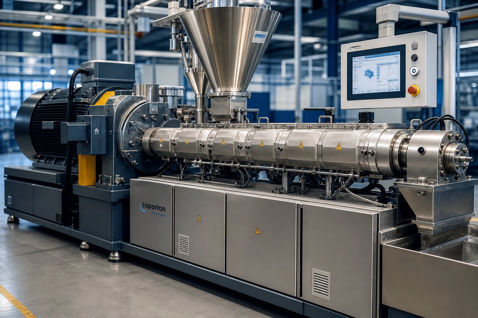
What Is an Intermeshing Twin Screw Extruder and Why It Matters
When you hear the term "twin screw extruder," it is easy to assume all dual-screw machines work the same way. They don't. The single detail that separates one twin screw extruder from another - and ultimately determines its mixing power, conveying behavior, and self-cleaning ability - is whether the screws intermesh.
Defining the Intermeshing Twin Screw Extruder
An intermeshing twin screw extruder is a processing machine in which the flights of one screw extend into the channels of the adjacent screw, creating a geometric interlock that produces controlled material conveying, intensive mixing, and a continuous self-wiping action along the barrel length.
That geometric interlock is the key distinction. In a non-intermeshing design, the two screws rotate side by side with a gap between them - they never physically engage. Material can pass freely between the screws, shear forces stay low, and there is no self-cleaning mechanism built into the geometry itself. A single screw extruder, by contrast, relies entirely on friction between the polymer and the barrel wall to push material forward, offering no screw-to-screw interaction at all.
An intermeshing twin screw extruder changes all of that. Because the flight tip of one screw reaches into the channel of its partner, the material has nowhere to stagnate. It is continuously scraped, redirected, and reoriented as it moves through the barrel. This is not a minor geometric detail - it fundamentally reshapes how energy transfers into the melt, how additives disperse, and how long any individual particle spends inside the machine.
These machines come in two primary variants. In co-rotating configurations, both screws turn in the same direction, and the flight of one screw approaches and wipes the root of the other in a sweeping motion. This produces a characteristic figure-eight material flow path and strong self-wiping behavior. In counter-rotating configurations, the screws turn in opposite directions, and the intermeshing zone creates enclosed, C-shaped chambers that act more like a positive displacement pump - forcibly pushing material forward with each rotation, similar to the calendering effect seen in gear pumps.
Why Intermeshing Designs Dominate Modern Processing
Imagine trying to blend a handful of fine pigment powder into a thick polymer melt using a single rotating screw. The pigment clumps. Dead zones form. Residence time varies wildly from one pellet to the next. Twin-screw extruders with intermeshing geometry solve these problems through three mechanisms that non-intermeshing and single screw machines simply cannot replicate:
- Self-wiping capability: The tight clearance between flight tip and opposing screw root prevents material buildup, minimizes thermal degradation, and keeps the barrel interior clean during operation.
- Controlled conveying: Whether through drag flow in co-rotating designs or positive displacement in counter-rotating ones, intermeshing twin-screw extruders give engineers precise control over how fast and how gently material travels through each processing zone.
- Superior mixing intensity: The repeated splitting, recombining, and reorienting of material streams across the intermeshing zone delivers both distributive and dispersive mixing far beyond what independent screws can achieve.
This combination of advantages explains why intermeshing configurations have become the most widely used twin screw architecture across polymer compounding, pharmaceutical hot-melt extrusion, food texturization, and reactive extrusion. They are not just popular - they are the engineering default for any application that demands tight residence time control, thorough additive incorporation, or processing of thermally sensitive formulations.
Yet most available resources either oversimplify the mechanics into a bullet-point feature list or bury them in academic notation that practicing engineers rarely have time to decode. This article bridges that gap. You'll find process-engineering depth on how intermeshing geometry actually drives material behavior - starting with the physical mechanism itself.
How the Intermeshing Twin Screw Mechanism Works at a Mechanical Level
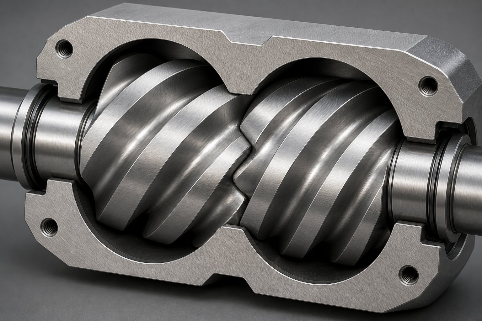
Picture two helical screws placed side by side inside a figure-eight-shaped barrel bore. The flight - the raised spiral ridge - of one screw reaches deep into the channel - the valley between flights - of the other. This physical overlap is what "intermesh" actually means in practice: no open gap exists between the two screws, so every cubic millimeter of material is forced to interact with both screw surfaces as it travels forward. That single geometric fact governs everything from shear intensity to residence time uniformity. But the way this interlock behaves depends entirely on which direction the twin screws rotate.
The Self-Wiping Effect in Co-Rotating Designs
When both screws turn in the same direction, something remarkable happens at the intermeshing zone. As one screw's flight sweeps forward, it approaches the root - the lowest-diameter surface - of the adjacent screw at a slight angle. Because both are spinning the same way, the flight tip traces a path that continuously scrapes material off the opposing screw's root surface and pushes it back into the open channel space.
Imagine dragging your thumb along the grooves of a spinning bolt. That wiping motion is constant and self-renewing. In a self-wiping twin screw extruder, the tight clearance between flight tip and opposing root - often less than a millimeter on production-scale machines - means polymer melt or powder has virtually no place to sit still. Dead zones disappear. Material that would otherwise overheat and degrade in a stagnant pocket gets swept away within fractions of a second.
This continuous renewal creates what engineers call a narrow residence time distribution. Every particle spends roughly the same amount of time inside the extruder, which is critical for thermally sensitive formulations and reactive extrusion processes where even a few seconds of excess heat exposure can trigger degradation. The material follows a figure-eight flow path, transferring from one screw to the other at the intermeshing region, constantly being split, reoriented, and recombined.
Closed C-Shaped Chambers in Counter-Rotating Designs
Counter-rotating twin screws flip the physics. Here, the two screws spin in opposite directions, and the intermeshing zone becomes a meeting point rather than a passing zone. As the flights converge from opposing rotational directions, they form enclosed, C-shaped pockets of material between the screw flights and the barrel wall.
You can think of each C-shaped chamber as a small, sealed compartment. With each rotation, these chambers physically carry a fixed volume of material forward along the barrel axis - much like individual buckets on a conveyor belt. This is true positive displacement conveying: the throughput becomes nearly independent of the material's viscosity or friction characteristics. Whether you're processing a slippery powder or a high-viscosity melt, each screw rotation advances the same volume.
The trade-off is shear. Because the opposing flights meet head-on, material in the intermeshing zone experiences a calendering effect - it gets squeezed between converging surfaces rather than swept along them. This generates localized pressure on the screws and barrel, which is one reason counter-rotating machines traditionally operate at lower speeds than their co-rotating counterparts.
How Geometric Interlock Controls Material Flow
The distinction between these two intermeshing twin screw mechanism types comes down to two fundamentally different conveying principles: drag flow and positive displacement.
In co-rotating designs, material transport is primarily driven by drag flow. The rotating screw surface drags polymer forward through frictional and viscous forces, while the intermeshing geometry prevents the material from simply spinning in place. The wiping action ensures constant surface renewal, but the actual forward movement depends on the interaction between screw speed, channel geometry, and melt viscosity. This makes co-rotating extruders highly flexible - engineers can adjust fill level, throughput, and mixing intensity somewhat independently by varying screw speed and feed rate.
In counter-rotating designs, the closed chambers dominate transport. Material is physically trapped and advanced regardless of its rheological properties. This positive displacement characteristic gives operators predictable, stable output - but it also means throughput is more rigidly tied to screw geometry and rotation speed, with less room to independently tune mixing conditions.
Here's the practical takeaway: co-rotating intermeshing geometry excels when you need aggressive mixing, thorough dispersion, and flexibility in screw profile design. Counter-rotating intermeshing geometry excels when gentle, predictable conveying matters more than mixing intensity - particularly for heat-sensitive materials that cannot tolerate the higher shear environment of co-rotating twin screws.
Both configurations share the core advantage that defines the intermeshing twin screw extruder: because one screw's flight occupies the other screw's channel, material cannot take shortcuts, cannot stagnate, and cannot avoid being processed. The geometric interlock is the engine behind every mixing, conveying, and self-cleaning benefit these machines deliver. How those benefits manifest across specific operating parameters, however, depends on the configuration chosen - a comparison that reveals even sharper contrasts when examined side by side.
Co-Rotating vs Counter-Rotating Intermeshing Configurations Compared
Knowing that co-rotating and counter-rotating twin screw extruder designs use the same intermeshing principle in fundamentally different ways raises an obvious question: which one should you actually choose? The answer depends on far more than rotation direction. Conveying mechanism, shear profile, mixing behavior, pressure generation, and even how you classify the machine within its own family all shift dramatically between configurations.
Co-Rotating Intermeshing Extruder Characteristics
A co-rotating twin screw extruder moves material primarily through drag flow. The rotating screw surfaces pull polymer forward via viscous and frictional forces, while the intermeshing geometry ensures that material constantly transfers between screws in a figure-eight path. This open-channel conveying approach means the extruder typically runs starve-fed - the feed rate is set by external feeders, and the screw speed is adjusted independently to optimize mixing intensity.
That independence is a powerful engineering lever. You can increase screw speed to boost shear and dispersive mixing without changing throughput, or raise feed rate while holding speed constant to reduce residence time. The high shear fields generated both at the intermeshing zone and between the screw flights and barrel wall make co-rotating designs exceptionally effective at breaking apart filler agglomerates, controlling polymer blend morphology, and driving reactive extrusion processes.
Mixing performance is equally impressive on the distributive side. Kneading blocks, gear-type mixing elements, and other modular screw components can be freely arranged along the shaft to impose complex deformation histories on the melt. The self-wiping action keeps residence time distribution narrow, which prevents thermal degradation and ensures batch-to-batch consistency. Typical screw speeds range from 200 to well over 1,200 rpm on modern machines, and throughputs scale aggressively with diameter.
Counter-Rotating Intermeshing Extruder Characteristics
The counter-rotating twin screw extruder plays by a different set of rules. Its closed C-shaped chambers act as positive displacement pumping elements, which means throughput is directly proportional to screw speed and largely independent of melt viscosity. Material gets trapped between converging flights and advanced forward in discrete volumetric packets.
This positive displacement character delivers exceptionally uniform pressure output - a major advantage when feeding dies that require stable flow. Shear intensity, however, stays comparatively low. Rather than the aggressive wiping action found in co-rotating designs, mixing in the counter-rotating intermeshing zone relies on a calendering effect: material is squeezed and stretched between converging screw surfaces under compressive and elongational deformation rather than high-shear rotational flow.
The result is gentle dispersion. Additives get incorporated without excessive heat generation, and materials with poor thermal stability - rigid PVC being the classic example - can be processed at temperatures much closer to their decomposition threshold without risk. Counter-rotating machines typically operate at higher fill levels and lower screw speeds, sometimes below 50 rpm for sensitive formulations. Self-wiping capability exists but is less aggressive than in co-rotating systems, meaning slightly wider residence time distributions are a practical trade-off.
HSEI vs LSLF Counter-Rotating Classifications
Here is where most comparison articles stop, and where the real nuance begins. Not all counter-rotating intermeshing extruders behave the same way. The industry recognizes two distinct operational families that share counter-rotating geometry but deliver radically different processing outcomes.
High-Speed Energy Input (HSEI) twin screw extruders operate at screw speeds up to 1,200 rpm or more. They use segmented screw elements on high-torque splined shafts, modular liquid-cooled barrels, and starve-fed operation - characteristics that, in practice, make them behave much more like co-rotating machines than traditional counter-rotating ones. HSEI extruders are designed for compounding, reactive processing, and devolatilization, where intensive energy input and aggressive mixing are required. The co-rotating intermeshing configuration dominates this HSEI category, though counter-rotating and non-intermeshing variants also serve specialty roles.
Low-Speed Late Fusion (LSLF) twin screw extruders operate at the opposite end of the spectrum - typically below 50 rpm. These are exclusively counter-rotating machines designed to mix at low shear and pump at uniform pressures. The "late fusion" label reflects their processing strategy: rather than melting material early through aggressive shear energy, LSLF designs allow the polymer to remain in a partially fused state further along the barrel before gentle compressive forces complete the melt. This approach is ideal for PVC pipes, profiles, and sheets where premature melting and excessive shear would trigger decomposition.
The practical implication? When someone says "counter-rotating twin screw extruder," you should immediately ask: HSEI or LSLF? The two share a rotation direction but almost nothing else in terms of processing philosophy, energy input, screw speed, or application range.
The following table puts all three major twin screw architectures side by side across the parameters that matter most to process engineers:
| Parameter | Co-Rotating Intermeshing | Counter-Rotating Intermeshing | Non-Intermeshing |
|---|---|---|---|
| Conveying Mechanism | Drag flow (starve-fed) | Positive displacement (flood-fed or starve-fed depending on HSEI/LSLF) | Drag flow with minimal screw interaction |
| Shear Rate | High (adjustable via screw speed and element selection) | Low to moderate (LSLF) or high (HSEI) | Low |
| Mixing Type | Strong dispersive and distributive mixing | Primarily compressive/elongational (calendering effect); moderate dispersive | Primarily distributive; weak dispersive |
| Pressure Generation | Moderate; relies on discharge elements | High and uniform; inherent to positive displacement geometry | Low; limited pressure-building capability |
| Self-Wiping Ability | Excellent; continuous flight-to-root wiping | Good but less aggressive than co-rotating | None; screws do not engage |
| Typical Throughput | High; scales aggressively with OD cubed | Moderate; limited by screw speed and chamber volume | Low to moderate |
| Residence Time Distribution | Narrow (tight control via self-wiping and starve feeding) | Narrow for LSLF at high fill; broader for HSEI at low fill | Broad; minimal geometric control |
| Primary Applications | Polymer compounding, reactive extrusion, masterbatch, pharmaceutical HME, food processing | PVC pipe and profile (LSLF); specialty compounding (HSEI counter-rotating) | Specialty blending, heat-sensitive materials, soft PVC |
One pattern stands out in this comparison: the co-rotating intermeshing configuration offers the widest operational flexibility, which is why it dominates the HSEI market across industries. The counter-rotating intermeshing design fills a critical niche wherever gentle positive displacement conveying and low shear outweigh the need for aggressive mixing - a niche that, for PVC processing alone, represents billions of kilograms of annual production.
These configuration-level differences, however, only tell part of the story. The actual performance you extract from either machine depends on something more granular: the specific geometric parameters of the screws and barrel that define free volume, torque capacity, and shear rate at every point along the processing length.
Key Screw Geometry Parameters That Drive Extruder Performance
Specification sheets for twin screw extruder screw design are packed with numbers - ratios, diameters, depths - yet most manufacturer pages never explain what those numbers actually control. If you have ever stared at an equipment data sheet wondering why one 60 mm machine outperforms another at the same screw speed, the answer almost always hides in a handful of geometric parameters. Understanding them is the difference between selecting an extruder that fits your process and inheriting someone else's compromise.
Understanding L/D Ratio and Its Processing Impact
The length-to-diameter ratio - L/D - describes how long the barrel is relative to the screw diameter. A 60 mm extruder with a 40:1 L/D has a barrel roughly 2,400 mm long. Sounds simple, but L/D dictates how many distinct processing zones you can fit along the screw profile: feeding, melting, mixing, venting, and pressure buildup each need physical space. A short L/D compresses these zones together, forcing trade-offs between mixing thoroughness and devolatilization efficiency.
Modern co-rotating intermeshing machines commonly range from 32:1 to 52:1 L/D. At the lower end, you'll find machines suited for straightforward blending tasks where a single mixing zone suffices. At 48:1 or above, engineers gain enough barrel real estate for multiple kneading sections, sequential vent ports, and dedicated reaction zones - critical for reactive extrusion or multi-stage devolatilization where residence time and sequential unit operations both matter. As a practical guideline, every additional 4 to 8 L/D segments give you roughly one more functional processing zone.
OD/ID Ratio, Flight Depth, and Free Volume
If L/D controls how many zones you get, the OD/ID ratio - outer screw diameter divided by inner screw diameter (the root) - controls how much material each zone can handle. A higher OD/ID ratio means deeper flight channels, greater free volume per diameter, and higher throughput capacity at equivalent screw speed.
Consider a real-world comparison: a 70 mm extruder with a 1.55 OD/ID ratio offers approximately 240 cc/diameter of free volume, while a 75 mm machine with a 1.66 OD/ID ratio delivers around 300 cc/diameter - a 30% increase in volumetric capacity despite only a modest jump in screw diameter. For volume-limited processes like low-bulk-density powders or highly filled compounds, that extra free volume directly translates to higher attainable throughput rates.
The trade-off? A higher OD/ID ratio reduces the cross-sectional area of the screw shaft, which limits torque transmission. Torque-limited processes - think fractional melt index HDPE or high-viscosity engineering resins - may actually benefit from a lower OD/ID ratio that sacrifices some free volume in exchange for a thicker, stronger shaft capable of transmitting more power. Flight depth, pitch, and helix angle all interact with this balance: deeper flights increase volumetric capacity and reduce average shear rate, while shallower flights boost pressure generation and intensify shear across the overflight gap.
Parallel vs Conical Barrel Geometry
Beyond these screw-level parameters, barrel geometry itself shapes what the extruder can do. A parallel twin screw extruder maintains a constant screw diameter from feed throat to discharge. This uniform bore is what makes modular screw element design possible - kneading blocks, conveying elements, and mixing discs all share the same diameter envelope, so engineers can rearrange the screw profile at will to match different formulations without changing the barrel. That modularity is the single biggest reason parallel configurations dominate compounding, masterbatch, and pharmaceutical applications.
A conical twin screw extruder takes the opposite approach. Its screws taper from a larger diameter at the feed end to a smaller one at the discharge. This tapered geometry creates a natural compression ratio along the barrel length - material is progressively squeezed as it advances, building pressure without requiring tight-pitch metering elements. Conical designs also allow larger center distances at the feed end, accommodating bigger bearings and higher torque transmission relative to the discharge diameter. PVC pipe and profile extrusion lines frequently use conical counter-rotating machines for exactly this reason: the gentle, progressive compression suits heat-sensitive materials, and the high torque capacity handles the demanding rheology of rigid PVC dry blends.
The table below summarizes how each geometric parameter influences processing performance:
| Parameter | Definition | Typical Range | Primary Processing Effect |
|---|---|---|---|
| L/D Ratio | Barrel length divided by screw diameter | 32:1 to 52:1 (co-rotating); 22:1 to 34:1 (conical counter-rotating) | Determines number of available processing zones, residence time, and devolatilization stages |
| OD/ID Ratio | Outer screw diameter divided by inner (root) diameter | 1.22 to 1.80 | Controls free volume, throughput capacity, shaft torque limits, and average shear rate |
| Free Volume (cc/dia) | Available channel volume per unit screw diameter | 100 to 300+ cc/diameter | Determines volumetric throughput ceiling; critical for low-bulk-density feeds |
| Flight Depth | Radial distance from screw root to flight tip | Varies with OD/ID ratio and screw diameter | Deeper flights increase capacity and lower shear; shallower flights raise pressure and shear |
| Pitch | Axial distance per full flight revolution | 0.5x to 1.5x screw diameter | Larger pitch increases conveying rate; smaller pitch builds pressure and extends residence time |
| Helix Angle | Angle of flight relative to the screw axis | Linked to pitch; typically 15 to 30 degrees | Influences drag flow efficiency and axial velocity of material along the screw |
| Barrel Geometry | Parallel (constant diameter) vs conical (tapered) | Parallel: uniform bore; Conical: 2:1 to 3:1 taper ratio | Parallel enables modular screw design; conical provides natural compression and high torque at feed end |
Every parameter in this table interacts with the others. A high OD/ID ratio paired with a long L/D gives you maximum free volume and maximum processing flexibility - but it also demands a drive system capable of transmitting enough torque through a relatively thin shaft at high speeds. Conversely, a conical twin screw extruder sidesteps some of those torque constraints through geometry alone, at the cost of screw profile modularity.
These geometric foundations set the stage for the real art of twin screw processing: deciding which specific screw elements to place along that barrel length, and how their arrangement creates the sequential processing zones that transform raw material into finished product.
Screw Element Configuration and Profile Design Essentials
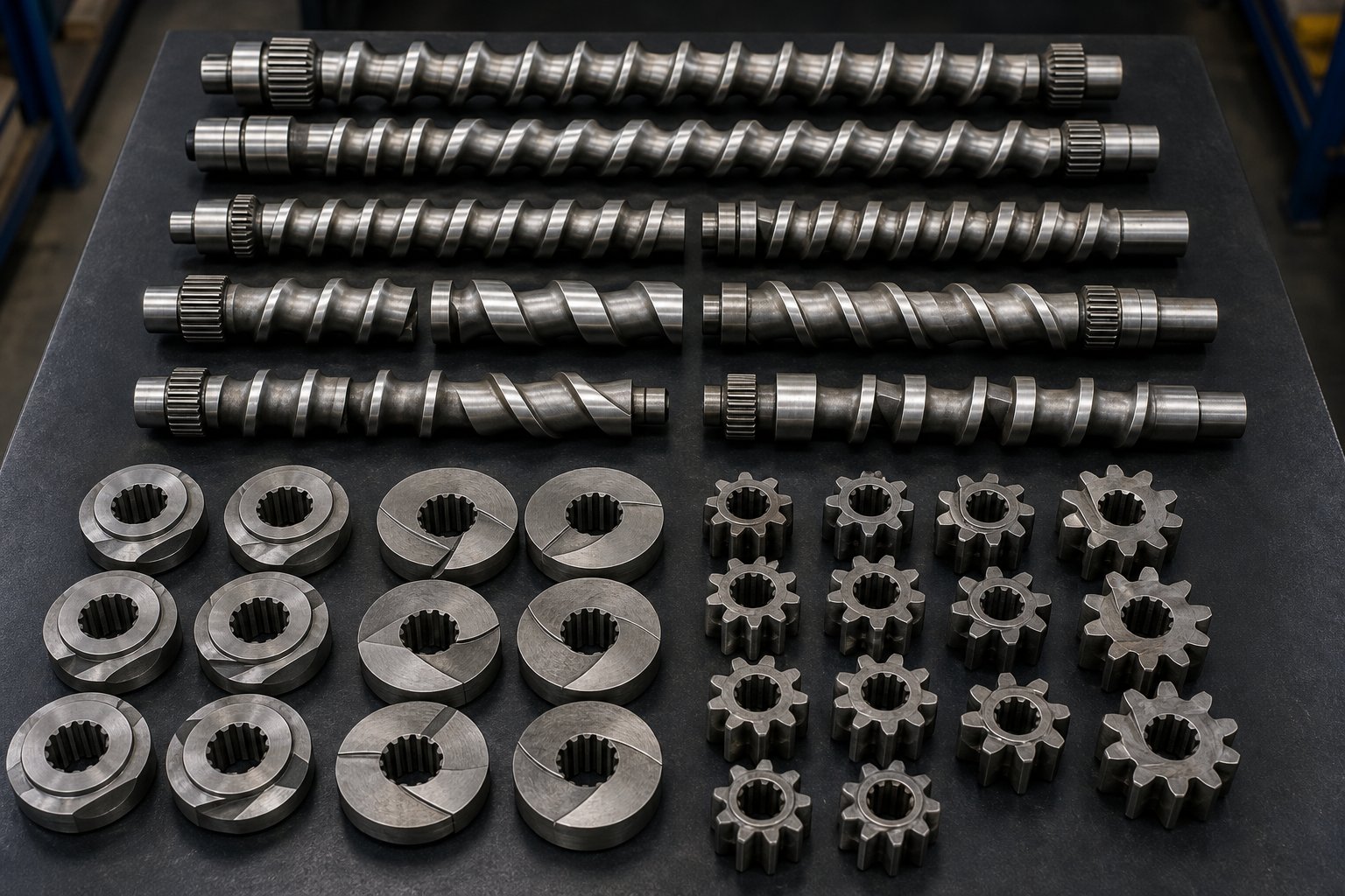
Barrel length and screw diameter define how much physical space you have to work with. The far more consequential decision is what you fill that space with. Every intermeshing twin screw extruder built on a modular platform uses interchangeable twin screw extruder screw elements - discrete components that slide onto a common splined shaft in whatever sequence the process demands. Swap one element for another, and you change how the machine melts, mixes, conveys, or pressurizes material. The entire personality of the extruder lives in the screw profile.
Three categories of elements make up the toolkit: conveying elements, kneading blocks, and specialized mixing elements. Each operates on different physical principles, and understanding those principles is what separates intentional screw design from trial-and-error guesswork.
Conveying Elements and Pitch Variation
Conveying elements are the workhorses of material transport. Visually, they look like traditional helical extruder screws - continuous flights wrapping around a cylindrical root. Their primary job is to move material forward (or backward) along the barrel, control fill level in each processing zone, and build pressure where needed.
The single most important variable is pitch - the axial distance between consecutive flights. Imagine two conveying elements sitting side by side on a shaft: one has a pitch equal to 1.5 times the screw diameter, the other a pitch of just 0.5 times the diameter. The large-pitch element acts like an aggressive conveyor belt, pulling material forward quickly and keeping the channel only partially filled. The small-pitch element slows things down, compresses the melt, and increases local pressure.
That relationship gives engineers a surprisingly powerful lever. By varying pitch along the screw length, you can create zones with dramatically different fill levels, residence times, and pressure profiles - all without changing screw speed or feed rate. A large-pitch element near the feed throat grips pellets or powder aggressively and prevents bridging. A tight-pitch element near the die builds stable pressure for consistent extrusion through the downstream tooling.
Conveying elements also come in reverse configurations. A left-handed flight on an otherwise right-handed screw pushes material backward against the main flow direction. This sounds counterproductive, but it serves a critical function: reverse conveying elements create a flow restriction that increases fill level and pressure upstream. Engineers use them to build melt seals ahead of vent ports, force material through kneading zones, and ensure that gases can escape at devolatilization openings without melt leaking out.
What conveying elements do not do particularly well is mix. They generate some shear as material passes over the flight tip and through the overflight gap, but compared to dedicated mixing elements, their distributive and dispersive capabilities are modest. Their contribution to mixing is indirect - by controlling fill level and pressure, they determine how effectively downstream kneading blocks and mixing elements can do their jobs.
Kneading Block Design and Mixing Intensity
If conveying elements are the workhorses, kneading blocks are the precision instruments. These elements consist of multiple disc-shaped lobes stacked along the shaft, each offset from its neighbor by a defined stagger angle. Three geometric variables - disc width, stagger angle, and the number of discs per block - give process engineers remarkably fine control over whether mixing is primarily distributive or dispersive.
Disc width controls how abruptly the melt's cross-sectional flow pattern changes as it passes each disc. Narrow discs create more frequent transitions, generating higher local pressure fluctuations and more intense shear peaks. This promotes dispersive mixing - the kind needed to fracture stubborn pigment agglomerates or break apart filler clusters. Wider discs produce smoother, more gradual flow transitions, favoring distributive mixing that spreads components evenly without necessarily breaking them apart.
Stagger angle - the angular offset between neighboring discs - is arguably the most influential single parameter. A low stagger angle, such as 30 degrees, maintains a net forward-pumping action through the kneading zone. Material passes through with moderate shear and reasonable residence time. As the stagger angle increases toward 60 degrees or steeper, net forward conveying drops, back-mixing intensifies, and shear stress rises sharply. At 90 degrees - a so-called neutral kneading block - the element has essentially zero conveying capacity. Material oscillates in place, experiencing maximum residence time and intense shear, until upstream pressure finally pushes it through.
Reverse kneading blocks take this one step further. Their stagger angle is oriented to push material backward, creating a powerful flow restriction and an extreme shear zone. They are indispensable for building melt seals and achieving the most aggressive dispersive mixing, but they also generate significant viscous heating and torque spikes, so their use demands careful attention to the material's thermal stability.
The practical shorthand is straightforward:
- Distributive mixing emphasis: Wide discs, low stagger angle (30 degrees), forward orientation - spreads additives evenly with moderate shear and low temperature rise
- Dispersive mixing emphasis: Narrow discs, high stagger angle (60 to 90 degrees), neutral or reverse orientation - breaks agglomerates through intense shear and pressure fluctuations, at the cost of higher melt temperature and torque
In real screw profiles, you rarely see a single kneading block type in isolation. A melting zone might start with forward kneading blocks at 30 degrees to begin softening pellets, transition to 60-degree blocks for aggressive melt completion, and finish with a short neutral block to ensure full plastication before the material enters a conveying-dominated mixing zone. Every combination is a deliberate trade-off between mixing intensity, energy input, and thermal exposure.
Building a Complete Screw Profile
Specialized mixing elements round out the toolkit. Gear-type mixing elements - sometimes called toothed or ZME (Zahnmisch) elements - feature rows of interlocking teeth that repeatedly split and recombine the melt stream without imposing the high shear stress characteristic of kneading blocks. They excel at distributive blending tasks: homogenizing color, incorporating liquid additives, or achieving uniform temperature distribution in the melt. Because their shear contribution is minimal, they are particularly valuable in fiber-reinforced compounds where preserving fiber length is critical, or in formulations where over-shearing would degrade sensitive additives.
Other specialty elements include interrupted-flight or "comb" conveying elements that divide melt streams for enhanced distribution, and slotted or perforated mixing discs designed for specific extensional-flow effects. The choice depends on the material system and the exact mixing mode required at that point in the profile.
When you assemble all three element categories in sequence along the shaft, the result is a complete screw profile - a tailored processing program built in hardware. A typical intermeshing twin screw extruder profile follows a logical zone progression:
- Feeding and solids conveying zone: Large-pitch conveying elements grip incoming pellets, powder, or flakes and transport them forward with minimal compression, keeping the channel partially filled to prevent feed-throat bridging
- Melting and plasticizing zone: A transition from conveying elements to progressively aggressive kneading blocks softens and melts the material through a combination of barrel heat conduction and viscous shear energy
- Primary mixing zone: Kneading blocks and distributive mixing elements disperse pigments, fillers, and additives into the molten matrix - this is where the core compounding work happens
- Devolatilization and venting zone: Reduced-pitch or large-pitch conveying elements lower local pressure and increase exposed melt surface area, allowing moisture, solvents, or reaction byproducts to escape through open vent ports; reverse elements or neutral kneading blocks upstream create the melt seal that prevents vent stuffing
- Secondary mixing and homogenization zone (optional): Additional distributive mixing elements or mild kneading blocks complete blending and equalize melt temperature without adding excessive shear
- Metering and pressure buildup zone: Tight-pitch conveying elements generate stable, uniform pressure to push melt through downstream screens, dies, or pelletizing equipment
This zone-by-zone logic is not a rigid template - it is a starting framework. A reactive extrusion process might include multiple sequential kneading and venting zones to handle staged reagent injection and byproduct removal. A masterbatch line processing carbon black might front-load dispersive kneading elements to break agglomerates early, then rely on distributive gear mixers downstream to achieve streak-free uniformity. A glass-fiber compound might deliberately minimize kneading intensity and use side-feeding downstream to preserve fiber length.
The engineering art lies in matching element selection to material behavior at each stage of the process. Screw extruders built on modular platforms make this iterative - you can pull the screws, rearrange elements, and test a revised profile in a matter of hours. That flexibility is one of the defining advantages of the intermeshing twin screw platform, and it is why experienced process engineers often maintain libraries of validated screw profiles organized by material family and application type.
Still, even the most carefully designed screw profile can only perform as intended when it operates within the right geometric envelope. How deeply the screws actually intermesh - whether fully, partially, or not at all - introduces another layer of processing trade-offs that many engineers overlook entirely.
How the Degree of Intermeshing Shapes Processing Outcomes
Most discussions about intermeshing twin screw extruder design treat the concept as binary - either the screws intermesh or they don't. In reality, intermeshing exists on a spectrum. The gap between a screw flight tip and the opposing screw root can be razor-thin or deliberately widened, and that dimensional choice reshapes nearly every processing characteristic the machine delivers. Engineers who overlook this variable often find themselves puzzled by performance differences between machines that appear identical on paper.
Fully Intermeshing vs Partially Intermeshing Designs
In a fully intermeshing twin screw extruder, the flight tip of one screw comes as close as physically practical to the root of the adjacent screw. Clearances are typically kept below one millimeter on production-scale machines - just enough to prevent metal-to-metal contact while maintaining aggressive self-wiping action. Imagine two gears meshing so tightly that nothing can slip between the teeth. That is the operating principle: material has virtually no opportunity to sit idle in the channel, because every rotation cycle sweeps the entire root surface clean.
This tight engagement produces several measurable effects. Dead zones - pockets where material can stagnate, overheat, and degrade - are functionally eliminated. Residence time distribution narrows dramatically because every particle follows a nearly identical path through the barrel. Thermal history becomes uniform, which matters enormously for heat-sensitive polymers and reactive formulations where even a few seconds of extra exposure can trigger crosslinking, chain scission, or discoloration.
A partially intermeshing design introduces a deliberate gap between the flight tip and the opposing root. You can think of it as loosening the engagement between those two gears. The screws still interact - one screw's flights still enter the other screw's channels - but the clearance is wide enough that material can pass through the gap without being fully wiped. This partial overlap sacrifices some self-cleaning effectiveness in exchange for practical benefits: lower localized shear stress in the intermeshing zone, reduced mechanical forces on the screw shafts, and greater tolerance for throughput fluctuations.
Why would anyone want less intermeshing? Consider a twinscrew application processing a highly filled compound with 70% calcium carbonate. The abrasive filler accelerates flight-tip wear, and the enormous particle loading demands high volumetric throughput. A partially intermeshing configuration reduces the mechanical intensity at the screw-to-screw interface, lowering wear rates and allowing higher fill levels without the torque penalties that a fully intermeshing geometry would impose. The trade-off is a broader residence time distribution and less precise mixing control - acceptable compromises when the material itself does not demand tight thermal uniformity.
How Intermeshing Degree Affects Residence Time and Mixing
The practical consequences of intermeshing degree ripple through five critical processing parameters, and understanding these trade-offs is what separates routine machine operation from genuine process engineering.
Material transport efficiency peaks in fully intermeshing designs. The tight geometry means the screw channel acts as a well-defined conduit with minimal leakage flow across the flight tip. In partially intermeshing configurations, some material leaks backward through the enlarged gap, reducing net forward conveying efficiency and making throughput slightly more sensitive to melt viscosity changes.
Mixing intensity follows a similar pattern. Full intermeshing forces every melt stream through the narrow gap between flight and root, subjecting it to intense shear deformation with each screw rotation. Partial intermeshing dilutes this effect - material that bypasses the gap entirely receives less mechanical work. For distributive mixing tasks where gentle blending suffices, this reduction may not matter. For dispersive challenges like breaking carbon black agglomerates or delaminating nanoclay platelets, the lost shear intensity becomes a real limitation.
Heat generation is the flip side of mixing intensity. Fully intermeshing screws convert more mechanical energy into viscous heating at the intermeshing zone. In processes where melt temperature must stay low - PVC compounding, for example, or biodegradable polymer blending - partially intermeshing geometry offers a natural way to moderate heat input without reducing screw speed. Non-intermeshing designs take this principle to its logical endpoint, eliminating screw-to-screw shear entirely and relying on rotor elements for mixing with minimal thermal buildup.
Pressure building capability also shifts with intermeshing degree. Tighter engagement reduces leakage flow, which means more of the screw's pumping action translates into downstream pressure. Partially intermeshing screws leak more, requiring longer metering zones or higher screw speeds to achieve the same die pressure - a constraint that shows up as reduced energy efficiency in pressure-limited applications like profile extrusion.
The table below puts these relationships into a structured comparison across all three configurations:
| Parameter | Fully Intermeshing | Partially Intermeshing | Non-Intermeshing |
|---|---|---|---|
| Self-Wiping Capability | Excellent; continuous flight-to-root wiping eliminates stagnation | Moderate; enlarged clearance allows some material bypass | None; screws operate independently with no geometric engagement |
| Residence Time Distribution | Narrow; uniform thermal history across all material streams | Moderate; some broadening due to leakage flow through gaps | Broad; material can circulate freely with minimal geometric constraint |
| Shear Intensity | High at intermeshing zone; adjustable via screw speed and element choice | Reduced at intermeshing zone; lower mechanical energy input per rotation | Low; shear generated primarily between screw flights and barrel wall |
| Throughput Flexibility | Moderate; tight geometry limits maximum fill level before torque constraints arise | High; relaxed clearances accommodate higher fill levels and throughput surges | High; open geometry accepts wide range of feed rates |
| Dead Zone Potential | Minimal; geometry prevents material accumulation | Low to moderate; bypass zones can develop at enlarged clearances | Significant; material can stagnate in inter-screw region |
| Heat Generation | Higher; tight clearance converts mechanical energy into viscous heat | Moderate; reduced screw-to-screw shear lowers energy dissipation | Lowest; minimal mechanical interaction between screws |
| Pressure Building Efficiency | High; minimal leakage flow across flight tips | Moderate; increased leakage reduces net pumping efficiency | Low; independent screws generate pressure less effectively |
| Wear Sensitivity | High; tight clearances amplify the impact of abrasive materials on flight tips | Lower; relaxed clearances reduce contact pressure and wear rates | Lowest; no screw-to-screw wear mechanism |
One critical point emerges from this comparison that specification sheets rarely mention: intermeshing degree is not fixed for the life of the machine. As flight tips wear from processing abrasive fillers, a fully intermeshing extruder gradually drifts toward a partially intermeshing condition. Self-wiping effectiveness declines, residence time distribution broadens, and mixing performance degrades - all without any visible change in screw speed, feed rate, or barrel temperature setpoints. This silent degradation is one of the most overlooked causes of product quality drift in long-running compounding operations.
Recognizing which degree of intermeshing your process actually requires - and monitoring whether wear has shifted that geometry away from its design intent - is a practical engineering discipline that pays dividends across every application sector. The choice between tight and relaxed engagement ultimately depends on the material you're processing and the specific performance demands of your industry, factors that vary dramatically from polymer compounding to pharmaceutical extrusion to PVC pipe production.
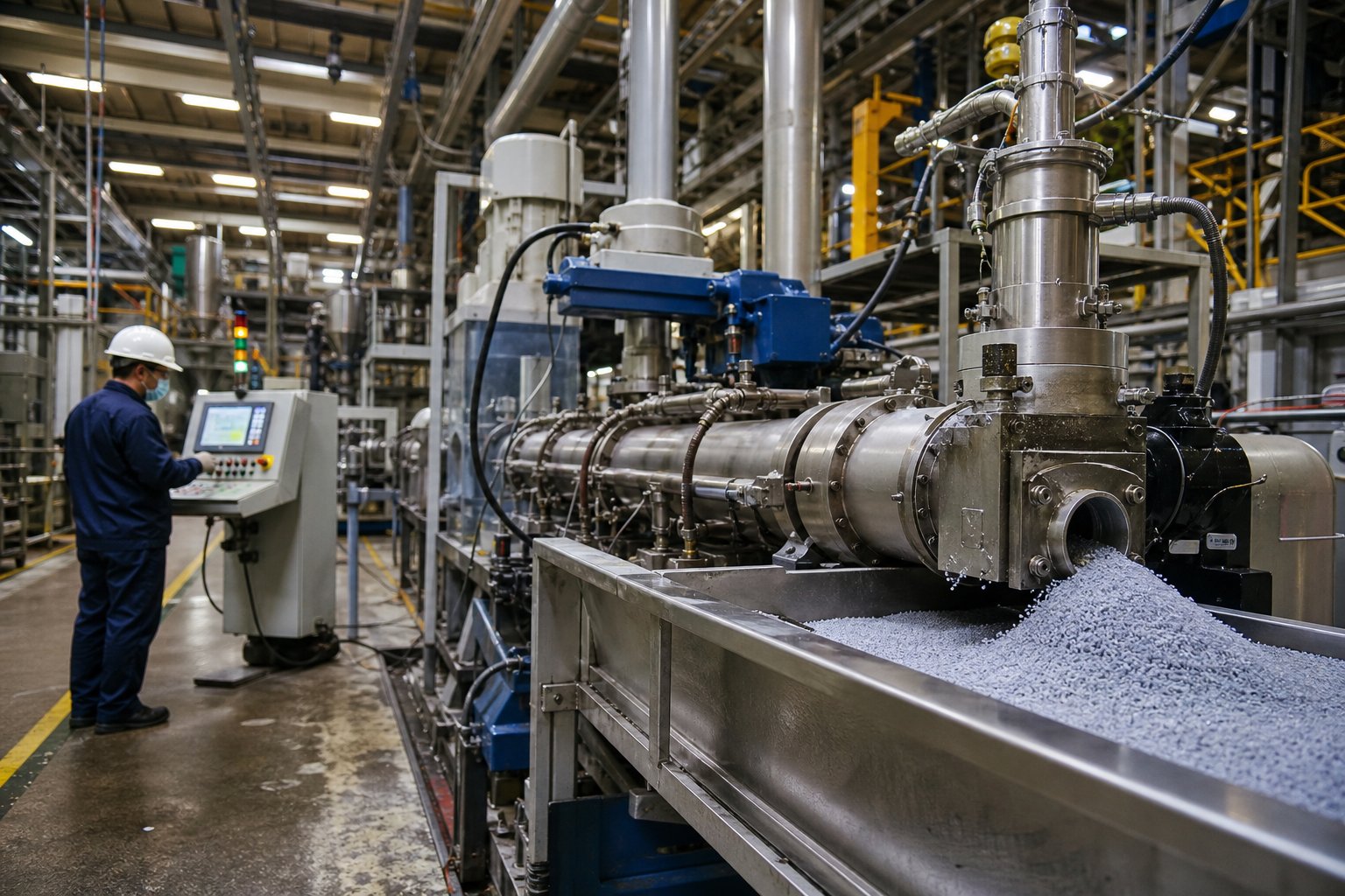
Industry Applications and Why Each Sector Chooses Its Configuration
Material behavior dictates machine selection - not the other way around. Every industry that relies on twin screw extrusion has landed on its preferred intermeshing configuration through decades of processing failures, reformulations, and hard-won optimization. The reasons behind those choices reveal far more about the technology than any feature list ever could.
The following summary maps each major application sector to its preferred intermeshing configuration and the core reason driving that choice:
- Polymer compounding (filled and reinforced thermoplastics): Co-rotating intermeshing - superior dispersive mixing intensity and high throughput capacity for breaking filler agglomerates and distributing reinforcements uniformly
- Masterbatch production: Co-rotating intermeshing - aggressive kneading capability needed to disperse pigments and additives at high concentrations without streaking
- PVC pipe and profile extrusion: Counter-rotating intermeshing (LSLF) - gentle positive-displacement conveying protects heat-sensitive PVC from thermal decomposition
- Pharmaceutical hot-melt extrusion: Co-rotating intermeshing - narrow residence time distribution and precise temperature control enable uniform API dispersion in polymer carriers
- Food processing and texturization: Co-rotating intermeshing - flexible screw profiles accommodate diverse ingredient mixing, moisture control, and structural transformation
- Reactive extrusion: Co-rotating intermeshing - controlled reaction environments with sequential feeding, mixing, and devolatilization zones along a single barrel
Each of these bullet points contains a story worth unpacking. The real value lies in understanding the material-specific processing logic that makes one configuration succeed and another fail.
Polymer Compounding and Masterbatch Production
Polymer compounding is where the co-rotating intermeshing configuration earns its dominance. A twin screw compounding extruder processing glass-fiber-reinforced nylon faces a completely different set of challenges than one running calcium-carbonate-filled polyolefin - yet both demand the same fundamental capability: intense, controllable mixing inside a self-wiping barrel.
Consider glass-fiber-filled nylon 6,6. The fibers arrive as chopped strands that must be wetted by the polymer melt, distributed uniformly throughout the matrix, and - critically - preserved at a target length that delivers the mechanical properties the end product requires. Too much shear and the fibers break down to dust, destroying tensile and impact performance. Too little mixing and fiber bundles survive intact, creating weak spots and surface defects. The solution is a carefully staged screw profile: aggressive kneading blocks in the early melting zone to plasticize the nylon quickly, followed by side-feeding the glass fiber downstream into an already molten matrix so it bypasses the highest-shear region entirely. Distributive gear-type mixing elements downstream then spread the fibers without fracturing them. Barrel temperatures run high - typically 270 to 290 degrees Celsius - and screw speeds stay moderate to balance dispersion against fiber breakage.
Calcium-carbonate-filled polyolefin presents the opposite problem. The mineral filler is inexpensive and non-reinforcing, so the goal is maximum loading at minimum cost, with uniform particle distribution and no agglomerates that would create surface defects in film or sheet. Here, screw profiles lean heavily on dispersive kneading blocks with 60- to 90-degree stagger angles to fracture CaCO3 clusters. Barrel temperatures drop to the 180 to 220 degree Celsius range typical for PE or PP, and screw speeds push higher - 400 to 800 rpm - because there is no fragile fiber to protect. The co-rotating architecture handles this naturally, since its drag-flow conveying accommodates high filler loadings without the torque penalties that a counter-rotating machine's positive displacement geometry would impose at elevated speeds.
Masterbatch production amplifies these dispersive mixing demands to an extreme. Color masterbatch, for example, may contain 40 to 60 percent pigment by weight - concentrations that create enormous viscosity spikes and stubborn agglomerates. Carbon black masterbatch is especially challenging because the primary particle aggregates resist breakup unless subjected to repeated high-shear passes. Co-rotating twin screw extruder applications in this space rely on multiple sequential kneading zones, often with neutral 90-degree blocks to maximize residence time in the high-shear region. The self-wiping action prevents pigment buildup on screw surfaces, which would otherwise cause color contamination during product changeovers - a practical advantage that saves hours of purging time in operations running multiple colors on the same line.
PVC Processing and Heat-Sensitive Materials
PVC turns the selection logic on its head. Polyvinyl chloride begins to degrade at temperatures only slightly above its processing window - rigid PVC compositions can start releasing hydrogen chloride gas at around 180 to 200 degrees Celsius, depending on stabilizer loading. The high-shear, high-speed environment that makes co-rotating machines so effective for compounding engineering resins becomes a liability here. Localized hot spots from aggressive kneading, combined with the viscous heat generated in the intermeshing zone at elevated screw speeds, can push PVC past its decomposition threshold before the material even exits the barrel.
Counter-rotating intermeshing extruders in the LSLF (low-speed late fusion) configuration solve this problem through fundamental physics rather than careful workaround. Their closed C-shaped chambers transport PVC dry blend forward at screw speeds below 50 rpm, generating minimal frictional heat. The "late fusion" processing strategy keeps material in a partially fused, powder-like state through most of the barrel length, delaying complete melting until the final zones where compression and moderate barrel heat finish the plasticization. This approach minimizes the total thermal history the PVC experiences, preserving stabilizer effectiveness and preventing the yellowing, black specks, and off-gassing that plague PVC processed on co-rotating equipment.
The positive displacement conveying inherent to counter-rotating geometry also provides stable, pulsation-free melt delivery to the die - a requirement for PVC pipe and profile extrusion where dimensional consistency directly determines product quality. Conical counter-rotating twin screw extruders are particularly popular in this segment. Their tapered geometry creates natural compression without requiring aggressive metering elements, and the larger feed-end bearings handle the high torque demands of rigid PVC dry blends without shaft deflection issues.
This same low-shear logic extends to other heat-sensitive materials. CPVC, certain biodegradable polymers like PLA blends, and wood-plastic composites (WPC) all benefit from the gentle conveying and controlled energy input that counter-rotating intermeshing machines provide. The key insight is that these applications don't need less mixing - they need mixing delivered through compressive and elongational deformation rather than rotational shear, which is precisely what the counter-rotating calendering effect supplies.
Pharmaceutical, Food, and Reactive Extrusion Applications
Pharmaceutical hot-melt extrusion represents perhaps the most demanding twin screw extruder application from a process control perspective. When you are dispersing an active pharmaceutical ingredient into a polymer carrier to create an amorphous solid dispersion, every variable matters: residence time must be tightly controlled to prevent API degradation, temperature profiles must stay within narrow windows to maintain amorphous stability, and mixing must be thorough enough to achieve molecular-level dispersion without over-shearing the formulation.
Co-rotating intermeshing machines dominate pharmaceutical twin screw extrusion for exactly the reasons outlined in earlier sections of this article. Their self-wiping action delivers narrow residence time distributions - residence times as short as 5 seconds are achievable on properly configured machines, with most pharmaceutical processes operating in the 20- to 60-second range. That consistency means every granule of API experiences the same thermal and mechanical history, which directly translates to batch-to-batch uniformity in dissolution performance. Modular screw profiles allow pharmaceutical engineers to place kneading zones, vent ports, and side-feeding points precisely where the formulation chemistry demands them, often within a compact 20:1 to 40:1 L/D barrel.
Food processing shares many of the same requirements. Texturization of plant-based proteins, starch modification, and flavor encapsulation all demand controlled mixing with precise thermal management. Co-rotating twin screw extrusion handles the wide range of rheological behaviors encountered in food systems - from low-viscosity slurries to stiff doughs - because its drag-flow conveying adapts naturally to viscosity changes along the barrel. The ability to inject water, oils, or flavor compounds at multiple downstream points through liquid injection ports makes the co-rotating platform uniquely versatile for food formulations that evolve chemically as they travel through the process.
Reactive extrusion pushes the co-rotating platform even further. In-barrel polymerization, grafting reactions, and controlled degradation processes all require the extruder to function simultaneously as a chemical reactor and a mixing device. The sequential zone architecture - feed, melt, react, devolatilize, pump - maps naturally onto co-rotating screw profiles with enough L/D to support each unit operation. Reaction byproducts like water, methanol, or CO2 are removed through vacuum vent ports positioned downstream of the reaction zone, with melt seals created by reverse kneading blocks or reverse conveying elements preventing vent flooding. The figure-eight material flow path inherent to co-rotating geometry ensures thorough mixing of reagents and uniform reaction conversion, while the narrow residence time distribution prevents over-reaction of early-arriving material.
One nuance worth noting: while co-rotating machines dominate pharmaceutical and reactive applications, research has shown that HSEI counter-rotating intermeshing extruders can sometimes deliver even narrower residence time distributions for specific formulations. A 2012 study comparing the two modes for compounding a poorly soluble API found reduced mean residence time and variance in counterrotation. This suggests the choice is not always automatic - process engineers working with novel formulations should evaluate both configurations on their merits rather than defaulting to co-rotating simply because it is the industry standard.
Across every one of these sectors, a consistent pattern emerges: the application's material sensitivity, mixing demands, and throughput targets determine which intermeshing configuration succeeds. Choosing the wrong one doesn't just reduce efficiency - it can make the process fundamentally unworkable. Yet even the correct configuration will eventually underperform if the machine itself deteriorates through operational wear, feed instabilities, or unchecked process drift - challenges that every production environment must learn to diagnose and correct.
Twin Screw Extruder Troubleshooting: Solving the Five Most Common Operational Failures
A perfectly configured screw profile running inside a well-specified barrel will still produce bad product if operational issues go undiagnosed. And in an extruder twin screw environment, the symptoms of trouble are often subtle - a creeping torque increase over several shifts, a gradual broadening of pellet size distribution, or a faint discoloration that only becomes obvious after downstream testing. By the time the alarm triggers or the product fails quality control, the root cause has usually been active for hours or days.
Effective twin screw extruder troubleshooting demands a systematic approach: recognize the symptom, trace it to a root cause, and apply a corrective action that prevents recurrence. The five failure modes covered here account for the vast majority of unplanned downtime and quality losses in intermeshing twin screw operations across compounding, masterbatch, recycling, and pelletizing applications.
Diagnosing Torque Overload and Feed Problems
Your motor current spikes. The overload alarm trips. The line goes down. Sound familiar? Torque overload is one of the most disruptive events in twin screw extrusion, and it almost always traces back to one of three causes: the machine is being asked to do too much work, the material is resisting that work more than expected, or the screw design itself is too aggressive for the operating conditions.
When feed rate exceeds the screw's conveying capacity at a given speed, material accumulates in the feed zone and compresses upstream of the first kneading section. This creates an enormous pressure spike that the drive system must overcome, pushing motor current past its rated limit. The fix sounds simple - reduce feed rate or increase screw speed - but the underlying question is why the imbalance developed. Common culprits include a feeder calibration drift that went unnoticed, a change in raw material bulk density between lots, or a hopper bridging event that caused intermittent surges of material into the feed throat.
Barrel temperatures that are too low in the melting zone create the same torque symptom through a different mechanism. Unmelted polymer pellets resist the shearing action of kneading blocks, forcing the screws to grind through solid particles rather than deform a viscous melt. The motor sees this as a sudden load increase. Checking barrel zone temperatures against the material's actual melting point - not just the setpoint on the HMI screen, but verified with an independent handheld thermometer - often reveals a failed heater band or a thermocouple reading several degrees off its true value.
Screw design itself can be the culprit. An overly aggressive kneading zone - too many narrow-disc, high-stagger-angle blocks in sequence - generates enormous shear stress that the drive must support. If a screw profile was designed for a low-viscosity polymer and then reused without modification for a high-viscosity engineering resin, the torque demand can easily exceed the gearbox rating. The solution is not always mechanical: sometimes simply rearranging one or two kneading blocks to reduce the peak shear intensity resolves the overload without sacrificing mixing quality.
Feed-zone bridging deserves special attention because it produces intermittent symptoms that mimic other problems. Bridging occurs when material forms an arch across the hopper throat or feed opening, momentarily starving the screws before collapsing and flooding them with a surge of material. The motor current oscillates, melt pressure fluctuates at the die, and pellet quality degrades - all without a clear, continuous alarm. Materials with irregular particle shapes, high moisture content, or electrostatic charging tendencies are especially prone to bridging. Installing a hopper agitator, maintaining feed-throat cooling at 20 to 40 degrees Celsius to prevent premature softening, and ensuring consistent pellet or powder sizing are the most effective preventive measures.
The distinction between starve feeding and flood feeding also matters here. Co-rotating intermeshing extruders are designed to run starve-fed, where the gravimetric feeder controls throughput independently of screw speed. Accidentally flooding a co-rotating machine - by setting the feed rate higher than the screw can convey at a given speed - fills channels to capacity, eliminates the partially filled zones that allow independent speed and throughput control, and drives torque toward the motor's upper limit. Monitoring percent torque relative to rated capacity in real time is the single most effective habit for preventing this failure mode.
Recognizing Barrel and Screw Wear Patterns
Wear is the silent thief of extruder performance. Unlike a torque overload that announces itself with an alarm, wear creeps in over weeks and months. Flight tips lose material. Barrel bore diameters grow. The tight clearances that define the intermeshing self-wiping effect gradually open up, and the machine drifts from a fully intermeshing condition toward a partially intermeshing one - with all the mixing, conveying, and residence time consequences discussed in earlier sections.
The primary drivers of barrel and screw wear fall into three categories. Abrasive wear comes from hard particles - glass fibers, mineral fillers like talc and calcium carbonate, and recycled materials containing contaminants - physically grinding against metal surfaces. Corrosive wear results from chemically aggressive additives, flame retardants, or degradation byproducts that attack the barrel liner at processing temperatures. Adhesive wear occurs when metal-to-metal contact develops due to screw deflection, misalignment, or inadequate lubrication in bearing surfaces.
Four zones within the extruder experience disproportionately high wear. The feed zone, where solid particles first contact barrel and screw surfaces under high frictional loads. The filler-addition zone, where side-fed glass fibers or minerals enter a partially filled channel and create intense localized abrasion. The mid-barrel region, where axial pressure and slight screw deflection cause the screw body to rub against the barrel wall. And the discharge zone, where gravity-induced sag in the cantilevered screw end creates uneven contact with the barrel bore.
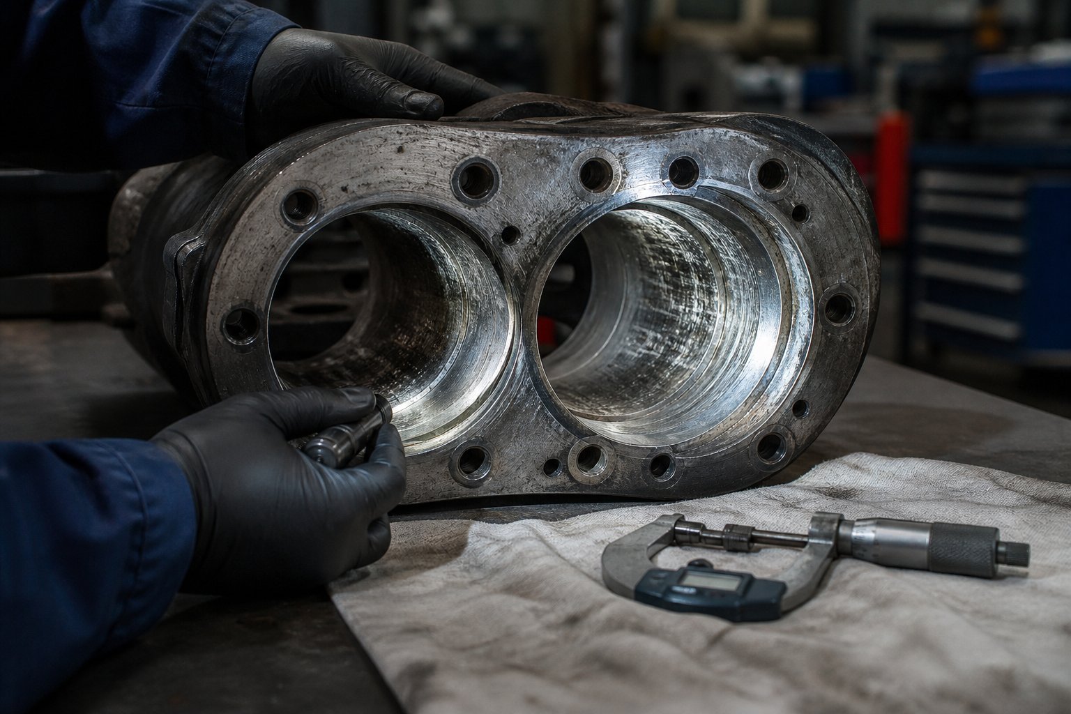
How do you know wear has become a problem? The symptoms accumulate gradually: a slow decline in output at constant screw speed, wider pellet size distribution, visible streaking in masterbatch products that previously ran clean, increased specific energy consumption, and broader residence time distribution that shows up as thermal degradation in heat-sensitive formulations. Measuring screw element diameters with a micrometer during scheduled maintenance is the definitive check - a wear limit of roughly 0.2 mm beyond nominal diameter is a common threshold beyond which mixing efficiency drops noticeably.
Addressing wear means matching barrel and screw metallurgy to the specific wear conditions your process imposes. Abrasive fillers demand hardened liners and flight tip coatings - bimetallic barrel liners with tungsten carbide or boron-based alloys resist particle erosion far longer than standard nitrided steel. Corrosive environments call for nickel-based alloys or stainless steel liners that withstand chemical attack at elevated temperatures. High-temperature processing of engineering resins like PPS or PEEK requires barrel materials that maintain hardness above 280 degrees Celsius, where conventional steels begin to soften.
When replacement becomes necessary, the quality and engineering specificity of the replacement barrel directly affects how long the machine runs before the next wear-related performance decline. Generic barrels may restore dimensions but often lack the metallurgical optimization needed for demanding applications. For compounding producers, recycling plants, and masterbatch manufacturers dealing with high-wear processing environments, sourcing barrels purpose-engineered for specific abrasion and corrosion conditions is a measurable investment in uptime. NANHAIYA's Parallel Twin Screw Barrel line, for example, is designed for exactly these scenarios - offering custom and replacement barrels tailored to the wear profiles encountered in filled compounds, recycled feedstocks, and high-pigment masterbatch operations where standard components simply do not hold up.
Preventing Material Degradation and Vent Flow Issues
Material degradation in an intermeshing twin screw extruder can stem from excessive residence time, excessive shear, or excessive temperature - and the three frequently compound each other. A worn kneading block that no longer generates efficient dispersive mixing forces the operator to increase screw speed to compensate, which raises shear heating. The higher melt temperature reduces viscosity, which extends residence time in partially filled zones. The combination pushes thermal exposure past the material's degradation threshold, producing yellowing, black specks, off-gassing, or measurable molecular weight reduction.
The troubleshooting discipline here is methodical. First, verify that barrel temperatures match the material's recommended processing window - not just the setpoint, but the actual temperature measured independently. A faulty thermocouple reading 10 degrees low causes the control system to overpower the heater, pushing the real barrel temperature well above target. Second, check the screw profile for unnecessary shear intensity. If kneading blocks were arranged for a previous product and never reconfigured for the current one, the melt may be receiving far more mechanical energy than needed. Third, inspect vent ports. Blocked vents trap volatile degradation byproducts inside the barrel, which accelerates further decomposition in a destructive feedback loop.
Vent flow problems deserve their own diagnosis because they interact with nearly every other failure mode. Vent stuffing - material flowing out through the vent port instead of gases escaping through it - is almost always a melt seal failure. The reverse kneading block or reverse conveying element upstream of the vent is supposed to create a full-channel plug of pressurized melt that prevents upstream material from reaching the vent opening. If that melt seal is inadequate - because the reverse element is worn, the fill level upstream is too high, or the barrel temperature in the sealing zone is too low for complete plasticization - material pushes through to the vent, clogs the vacuum line, and destroys devolatilization performance.
Excessive throughput is another common vent stuffing trigger. When feed rate exceeds what the screw can convey through the venting zone at a comfortable fill level, back-pressure forces melt into the vent opening. The corrective action is straightforward: reduce feed rate by 10 to 15 percent, verify that vent-zone conveying elements have adequate pitch to maintain low fill, and ensure that upstream kneading elements are generating a proper melt seal. Cleaning blocked vents with non-metallic tools during scheduled stops, rather than waiting for vacuum loss to force an unplanned shutdown, should be standard operating practice.
The following table consolidates the five most common operational challenges into a quick-reference troubleshooting guide:
| Problem | Common Causes | Symptoms | Corrective Actions |
|---|---|---|---|
| Torque Overload | Feed rate too high relative to screw speed; barrel temperatures too low in melting zone; screw profile too aggressive for material viscosity; material bulk density change between lots | Motor current exceeds rated limit; overload alarm trips; drive system shuts down automatically; intermittent current spikes during feed surges | Reduce feed rate or increase screw speed to restore balance; verify barrel zone temperatures with independent measurement; replace failed heater bands; reconfigure kneading blocks to reduce peak shear intensity; recalibrate gravimetric feeder |
| Barrel and Screw Wear | Abrasive fillers (glass fiber, CaCO3, talc) eroding flight tips and barrel liner; corrosive additives attacking metal surfaces; screw deflection causing metal-to-metal contact; operation beyond rated torque or speed limits | Gradual output decline at constant speed; wider pellet size distribution; visible streaking or color inconsistency in masterbatch; increased specific energy consumption; broader residence time distribution | Measure screw element diameters during scheduled maintenance (replace if wear exceeds 0.2 mm); upgrade to bimetallic or PM-steel barrel liners for abrasive applications; check and correct screw alignment; source replacement barrels engineered for specific wear conditions |
| Material Degradation | Excessive residence time from low fill or incorrect screw speed; excessive shear from overly aggressive kneading blocks; barrel temperature above material stability threshold; blocked vents trapping volatile decomposition products | Yellowing or discoloration of extrudate; black specks or carbonized particles; burning odor at die or vent; measurable drop in molecular weight or mechanical properties; bubble formation in extrudate | Verify actual barrel temperatures against setpoints using handheld thermometer; reduce kneading intensity by substituting lower-stagger-angle blocks; increase screw speed to shorten residence time; clean vent ports and restore vacuum level; pre-dry hygroscopic materials to below 0.05% moisture |
| Feed-Zone Bridging | Material arching in hopper or feed throat; premature softening from insufficient feed-throat cooling; irregular particle size or shape; high moisture or electrostatic charge in feed material | Intermittent torque and pressure fluctuations; surging output followed by brief starvation; uneven pellet quality within the same production run; audible changes in motor load | Install hopper agitator or vibrator; maintain feed-throat cooling water at 20-40 degrees Celsius; ensure consistent pellet or powder sizing; use anti-caking agents for hygroscopic additives; switch from flood feeding to controlled starve feeding with gravimetric feeder |
| Vent Stuffing | Inadequate melt seal from worn or incorrectly positioned reverse elements; excessive throughput overwhelming vent-zone conveying capacity; insufficient plasticization upstream of vent creating porous melt seal; vacuum level set too high | Material overflowing from vent port; sharp drop in vacuum level; loss of devolatilization efficiency; increased volatile content in finished product; material buildup in vacuum line | Verify upstream melt seal integrity by checking reverse element condition; reduce feed rate by 10-15%; ensure vent-zone conveying elements have adequate pitch; clean vent port and vacuum line; reduce vacuum setpoint to -0.06 to -0.07 MPa and increase gradually |
A pattern runs through every row of that table: most operational failures in intermeshing twin screw extruders trace back to a mismatch between what the machine was configured to do and what the current process actually demands. Material lots change. Screw elements wear. Feeders drift out of calibration. The operators who keep their lines running consistently are the ones who treat twin screw extruder troubleshooting as a continuous discipline - not a reactive scramble when the alarm sounds - and who invest in monitoring the machine's mechanical condition, especially wear-critical components like barrel liners and flight tips, with the same rigor they apply to process parameters.
Resolving these operational challenges, however, is only half the equation. The longer-term question - which intermeshing configuration, screw profile, and component specification should you choose in the first place to minimize the likelihood of these problems - requires a structured selection framework that ties every decision back to your specific material, throughput, and quality targets.
Selecting the Right Intermeshing Twin Screw Setup for Your Process
Every troubleshooting table, every wear pattern, every torque overload event described in the preceding sections shares a common thread: most operational problems originate in decisions made before the machine ever starts running. The wrong configuration for your material. An undersized drive for your throughput target. A barrel metallurgy that doesn't match your filler chemistry. Getting these foundational choices right eliminates entire categories of downstream headaches - and the decision process itself is more structured than most buyers realize.
Matching Configuration to Material and Process Requirements
Imagine you're specifying a new twin-screw extruder machine for a production line that will run three different compound families over the next five years. How do you avoid a choice that works brilliantly for one material and fails for the other two? The answer is a disciplined, step-by-step evaluation that weighs your material's thermal sensitivity, your mixing demands, your throughput targets, and your downstream equipment constraints against the capabilities of each intermeshing configuration.
The following decision process distills the engineering logic covered throughout this article into a practical sequence any process engineer or procurement team can follow:
- Characterize your material's thermal sensitivity. Identify the processing window - the gap between the minimum temperature for adequate melting and the onset of degradation. Materials with a narrow window below 20 degrees Celsius (rigid PVC, certain biodegradable blends, heat-stabilized CPVC) strongly favor counter-rotating intermeshing LSLF configurations that minimize shear heating and allow late fusion. Materials with a wide processing window (polyolefins, nylon, ABS) accommodate co-rotating designs without thermal risk.
- Define your mixing requirements. Determine whether your formulation demands primarily dispersive mixing (breaking agglomerates of pigments, nanofillers, or flame retardants), distributive mixing (spreading pre-dispersed additives evenly), or both. Dispersive-dominant applications favor co-rotating intermeshing machines with aggressive kneading block configurations. Distributive-only applications may succeed on either platform, though co-rotating designs offer greater screw profile flexibility.
- Establish your throughput target and scale it against screw diameter. Co-rotating intermeshing extruders scale throughput roughly with the cube of screw diameter - a 90 mm machine can produce roughly three times the output of a 60 mm machine at equivalent specific throughput. Counter-rotating LSLF machines scale more linearly with chamber volume. Match your production rate requirement to the manufacturer's documented throughput range for your material class, not generic maximum ratings.
- Evaluate pressure generation needs. If your downstream equipment - a profile die, sheet die, or underwater pelletizer - requires stable, high melt pressure, counter-rotating intermeshing geometry provides inherently uniform positive-displacement pumping. Co-rotating machines can generate adequate pressure through tight-pitch metering elements, but pressure stability depends more on maintaining consistent fill level and screw speed control.
- Assess filler type and loading level. Abrasive fillers above 30% loading accelerate flight tip and barrel wear in fully intermeshing designs. If your formulation includes glass fiber above 20%, mineral fillers above 40%, or recycled streams with metal or grit contamination, factor accelerated wear into the selection by specifying appropriate barrel metallurgy and planning for shorter maintenance intervals - or consider partially intermeshing configurations that reduce contact pressure at the screw-to-screw interface.
- Confirm downstream equipment compatibility. Your extruder must deliver melt at the viscosity, temperature, and pressure range your die, pelletizer, or calendering stack requires. A double screw extruder machine feeding an underwater pelletizer needs consistent die pressure within a tight band. One feeding a flat die for sheet extrusion needs exceptional melt temperature uniformity. Verify that the configuration you've selected can meet these downstream specifications under your actual operating conditions, not just at the manufacturer's test stand.
- Plan for formulation flexibility. If your production schedule includes frequent material changes, co-rotating intermeshing extruders with modular screw profiles offer the fastest changeover capability. Their self-wiping geometry reduces purging time between colors or compounds, and the ability to rearrange screw elements without changing the barrel gives you latitude to optimize for each new formulation. Counter-rotating machines, while excellent within their niche, offer less profile flexibility and longer purging cycles.
This sequence is not a checklist to rush through - it is a prioritization framework. Material sensitivity comes first because it can eliminate an entire configuration category from consideration before you ever discuss throughput or mixing. An extrusor that delivers perfect dispersion at 800 rpm means nothing if the polymer degrades at the shear rates that speed produces.
Barrel and Screw Specification as Performance Multipliers
Selecting the right intermeshing configuration gets you to the right machine architecture. Specifying the right barrel and screw components determines whether that architecture actually delivers its potential in production.
Barrel metallurgy must match the chemical and mechanical aggression of your process. This is not an abstract principle - it is a concrete cost calculation. A nitrided 4140 steel barrel processing 40% glass-filled PA66 may wear through its hardened case in as few as 4,000 operating hours, while a bimetallic barrel with tungsten carbide liner in the same application can exceed 20,000 hours. That five-fold difference in service life translates directly into fewer unplanned shutdowns, more consistent product quality, and a dramatically lower total cost of ownership - even though the bimetallic barrel costs three to four times more upfront.
Screw element selection follows the same logic. Kneading blocks, conveying elements, and mixing discs must balance mixing intensity against energy input for your specific polymer system. An element configuration optimized for carbon black masterbatch - narrow discs, 90-degree stagger angles, multiple sequential kneading zones - would destroy fiber length in a glass-reinforced nylon compound within seconds. The screw profile is not a one-time decision; it is a living specification that should evolve as your product portfolio changes, your raw material sources shift, and your quality targets tighten.
Corrosive processing environments add another layer. PVC, halogenated flame retardants, and fluoropolymers all generate acidic byproducts at processing temperatures. Standard carbon steel barrels corrode measurably within months under these conditions. Nickel-based bimetallic liners or Stellite-overlaid screw flights resist chemical attack at rates eight to twelve times lower than nitrided steel - a specification detail that determines whether a barrel lasts one season or several years.
Building a Reliable Supply Chain for Replacement Components
Even the best-specified barrel and screw assembly is a consumable. Wear is not a defect - it is an engineering reality of processing abrasive, corrosive, or high-temperature materials at industrial throughputs. What separates well-run operations from reactive ones is whether replacement components are sourced proactively, with the same engineering rigor applied to the original specification, or panic-ordered when performance degrades past the point of acceptable product quality.
Three principles guide effective replacement component procurement. First, document your wear patterns. Record screw element diameters and barrel bore measurements at every scheduled maintenance interval. Trend data - not single measurements - tells you when replacement is approaching and which zones wear fastest, allowing you to stock the specific elements and barrel segments that your process consumes rather than maintaining expensive inventories of parts you rarely need.
Second, match replacement metallurgy to your actual wear mechanism. A barrel that failed due to abrasive wear from mineral fillers needs a different liner chemistry than one that failed from corrosive attack by PVC degradation products. Specifying a generic "wear-resistant" replacement without diagnosing the failure mode guarantees you'll repeat the same service life - or worse.
Third, qualify suppliers who engineer barrels and screws for specific processing conditions rather than offering one-size-fits-all commodity parts. For compounding producers, masterbatch manufacturers, recycling plants, and plastic pelletizing operations dealing with demanding wear environments, this means working with partners who understand the relationship between barrel metallurgy, screw geometry, and process performance. NANHAIYA's Parallel Twin Screw Barrel product line represents one such option - purpose-built for applications requiring stable conveying, consistent mixing performance, and durability under high-wear conditions including heavily filled compounds and recycled feedstocks. Evaluating suppliers like this alongside your existing sources gives you the comparative data to make procurement decisions based on documented performance rather than habit.
The broader point matters more than any single supplier recommendation: your intermeshing twin screw extruder is only as capable as the weakest component in its wear path. Configuration selection, screw profile design, barrel metallurgy, and replacement component sourcing are not four separate decisions - they are four facets of a single integrated engineering choice. Get them aligned, and the machine delivers its design potential shift after shift. Let any one drift out of specification, and the troubleshooting table from the previous section becomes your daily operating reality.
Frequently Asked Questions About Intermeshing Twin Screw Extruders
1. What is the difference between intermeshing and non-intermeshing twin screw extruders?
In an intermeshing twin screw extruder, the flights of one screw physically extend into the channels of the adjacent screw, creating a geometric interlock. This produces self-wiping action, controlled conveying, and intensive mixing. In a non-intermeshing design, the two screws rotate side by side with a gap between them — they never physically engage. Material can pass freely between the screws, shear forces remain low, and there is no built-in self-cleaning mechanism. The intermeshing design delivers narrower residence time distribution, superior additive dispersion, and reduced dead zones compared to non-intermeshing configurations, which is why it dominates applications in polymer compounding, pharmaceutical hot-melt extrusion, and food processing.
2. Why is a co-rotating twin screw extruder preferred over counter-rotating for polymer compounding?
Co-rotating intermeshing extruders generate high shear fields through their figure-eight material flow path and aggressive self-wiping action, making them ideal for breaking apart filler agglomerates, controlling polymer blend morphology, and achieving thorough dispersive and distributive mixing. They also allow independent control of screw speed and feed rate (starve-fed operation), giving engineers the flexibility to optimize mixing intensity without changing throughput. Counter-rotating machines, by contrast, rely on positive displacement conveying with lower shear — better suited for heat-sensitive materials like PVC but insufficient for the intense mixing demands of filled and reinforced thermoplastics, masterbatch, or reactive extrusion processes.
3. What does the OD/ID ratio mean on a twin screw extruder and why does it matter?
The OD/ID ratio is the outer screw diameter divided by the inner (root) diameter. A higher OD/ID ratio means deeper screw channels, greater free volume per unit diameter, and higher throughput capacity at equivalent screw speed — critical for processing low-bulk-density powders or highly filled compounds. However, increasing the OD/ID ratio reduces shaft cross-sectional area, which limits torque transmission. Torque-limited processes involving high-viscosity resins may benefit from a lower OD/ID ratio that sacrifices some free volume for a stronger shaft. Typical values range from 1.22 to 1.80, and the right choice depends on balancing volumetric capacity against the mechanical power your formulation demands.
4. How do you prevent vent stuffing in an intermeshing twin screw extruder?
Vent stuffing occurs when material flows out through the vent port instead of allowing gases to escape. The root cause is almost always a failed or inadequate melt seal upstream of the vent. To prevent it, ensure the reverse kneading block or reverse conveying element upstream of the vent is in good condition and properly positioned to create a pressurized melt plug. Reduce feed rate by 10 to 15 percent if throughput is overwhelming the vent-zone conveying capacity. Verify that vent-zone conveying elements have sufficient pitch to maintain low fill levels, and clean vent ports and vacuum lines during scheduled maintenance stops rather than waiting for vacuum loss to force unplanned downtime.
5. What is the difference between HSEI and LSLF counter-rotating twin screw extruders?
HSEI (High-Speed Energy Input) counter-rotating extruders operate at screw speeds up to 1,200 rpm or more, using segmented screw elements and starve-fed operation. They behave much more like co-rotating machines, delivering intensive energy input for compounding, reactive processing, and devolatilization. LSLF (Low-Speed Late Fusion) counter-rotating extruders operate below 50 rpm, using positive-displacement conveying to transport material gently with minimal frictional heat. The 'late fusion' strategy keeps polymer partially fused through most of the barrel, delaying complete melting until the final zones — ideal for heat-sensitive materials like rigid PVC where premature melting and excessive shear would trigger decomposition.
Written by
Nanhaiya Technical Team
Zhoushan Nanhaiya Plastic Machinery Co., Ltd.
The Nanhaiya technical team supports screw and barrel manufacturing projects through application review, technical communication, custom manufacturing coordination, and production and quality control.
Discuss Your Application
Related Articles
More insights on screw barrel technology and plastics processing.

Extruder Machine Decoded: From Raw Pellet To Finished Product
Oct 6, 2026
Learn how an extruder machine works, compare single-screw vs. twin-screw types, and get expert guidance on specs, troubleshooting, and selection.
Read Article
PE Pipe Making Machine Decoded: From Raw Resin to Flawless Pipe
Oct 4, 2026
Learn how a PE pipe making machine works, from resin to finished pipe. Covers components, material grades, automation, troubleshooting, and buyer selection tips.
Read Article
PVC Profile Making Machine Decoded: From Raw Resin To Profit
Oct 3, 2026
Learn how a PVC profile making machine works — extrusion process steps, key technical parameters, die design, calibration methods, maintenance, and total cost of ownership.
Read ArticleLooking for something else?
Search by material, symptom or product and jump straight to the relevant page.
These are navigation suggestions based on keyword matching — not a quotation, not a delivery commitment, and not a substitute for engineering review. Final specification is confirmed by our engineers against your drawings and processed material.
Need help with screw barrel selection?
Share your machine model, processed material and application. Our team can help with pricing and technical support.