

What Is an Injection Screw Barrel and Why It Matters
Imagine running thousands of molding cycles a day, only to discover that inconsistent shot weights, surface blemishes, and dimensional drift have been quietly building for weeks. Where does the problem start? Not at the mold. Not at the clamp. It starts inside the plasticizing assembly — the component you probably inspect least.
Defining the Injection Screw Barrel
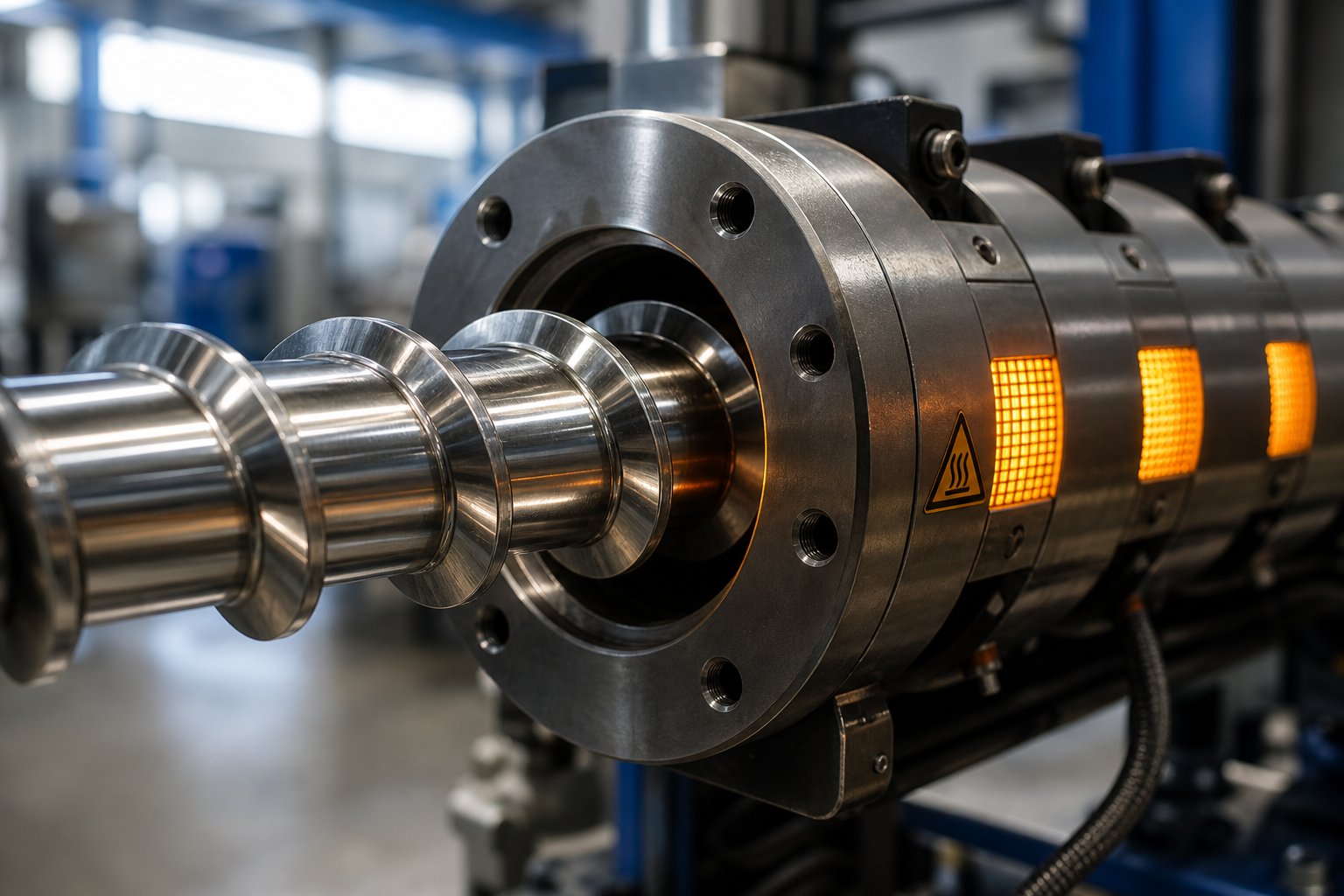
An injection screw barrel is the plasticizing core of every injection molding machine. It consists of a helical screw rotating inside a heated cylindrical barrel, working together to convey, melt, mix, and meter polymer into a precise shot that fills the mold cavity under high pressure.
The injection molding screw sits inside the injection molding barrel like a precision engine inside a cylinder block. Solid plastic pellets drop from the hopper into the rear of the barrel, where the rotating screw pushes them forward through progressively hotter zones. Friction between the screw flights and the barrel wall, combined with external heater bands, transforms those pellets into a homogeneous melt. Once enough material accumulates at the front, the screw drives forward as a ram and injects the molten polymer into the mold.
That entire sequence — conveying, compressing, melting, mixing, and injecting — depends on the condition of this single assembly. When it works correctly, you barely think about it. When it wears, every part coming off the line tells the story.
Why This Component Determines Part Quality
Your mold can't fix what the barrel messed up. If the melt reaching the cavity carries temperature variations, unmixed additives, or trapped air, those flaws show up as color streaks, weak weld lines, splay marks, and unpredictable dimensions. Shot consistency, surface finish, and dimensional stability all trace back to how well the screw and barrel plasticize the resin.
Even small increases in the clearance between screw flight and barrel bore allow molten polymer to leak backward during injection, causing shot-weight variation that compounds across every cycle. A worn non-return valve amplifies the problem further. You'll notice longer recovery times, cushion position drift, and parts that alternate between slightly short and slightly flashed — classic signs that the plasticizing heart of your machine needs attention.
Injection vs. Extrusion Screw Barrels at a Glance
At first glance, an injection molding barrel and an extrusion barrel look similar — both house a helical screw inside a heated cylinder. The operational differences, however, are significant:
- Reciprocating action: An injection molding screw both rotates and moves axially. It retracts while plasticizing, then thrusts forward to inject the shot. An extruder screw barrel only rotates continuously — it never acts as a ram.
- Non-return valve: Because the injection screw must push melt forward without backflow, it requires a check ring or ball-check valve at its tip. No extruder barrel needs this component.
- Intermittent vs. continuous operation: Extrusion is a steady-state process. Injection molding is cyclical — heat, shear, and pressure spike and relax with every shot. This intermittent cycle creates unique wear patterns and thermal stress that extruder screws and barrels never experience.
These distinctions matter because selecting an extruder screw barrel design for an injection application — or ignoring the reciprocating wear dynamics — leads to premature failure and melt quality issues that no process adjustment can overcome.
The sections ahead unpack everything you need to manage this critical assembly across its full lifecycle: internal anatomy and functional zones, screw design variations, barrel and screw material selection, resin-to-hardware matching, process settings that accelerate or slow wear, hands-on maintenance procedures, and a diagnostic troubleshooting framework for the most common failures. It's the complete picture — and the wear signs hiding inside it are the ones most processors miss.
Anatomy of the Injection Screw Barrel Assembly
Every wear symptom you chase on the production floor — cushion drift, color streaks, unexplained short shots — traces back to a specific location inside the plasticizing assembly. Understanding where each function happens, and which component handles it, is the fastest path to identifying what is actually failing. Think of this section as a map. When a problem appears, you'll know exactly where to look.
Feed, Compression, and Metering Zones Explained
The injection screw is not one uniform helix. It is divided into three distinct functional zones, each engineered for a specific stage of material transformation.
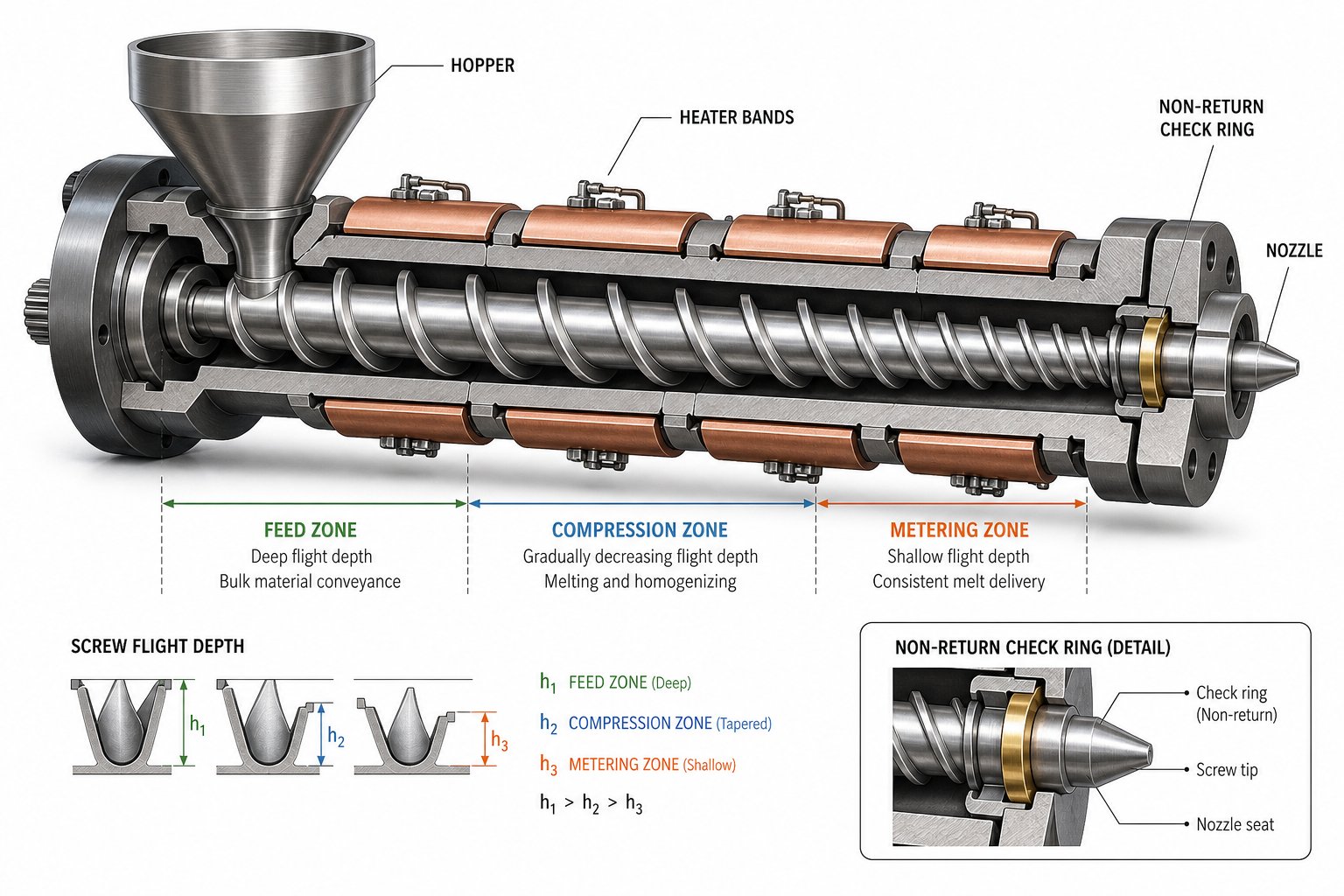
- Feed zone: This rearmost section features deep, evenly spaced flights. Its job is straightforward — accept solid pellets from the hopper and convey them forward into the barrel. Flight depth here is at its maximum, creating a large channel volume that grabs and pushes raw material ahead. No significant melting occurs yet; friction between the pellet mass, the screw root, and the barrel wall generates the initial heat that softens the outer layer of each granule.
- Compression (transition) zone: Picture the channel depth gradually shrinking as you move toward the front of the screw. That taper squeezes the solid bed against the barrel wall, dramatically increasing shear and frictional heat. This is where most melting takes place. The decreasing flight depth also forces trapped air backward, out through the feed throat, rather than allowing it to travel forward into the melt pool. A properly designed compression zone is the single biggest factor in eliminating unmelts and air entrapment.
- Metering zone: At the front end of the screw, the channel depth levels off at its shallowest. The purpose here is consistency — delivering a fully molten, thermally uniform stream of polymer at a predictable pressure and flow rate. The shallow, constant-depth channel subjects the melt to controlled shear that homogenizes temperature and mixes any remaining solid fragments, colorants, or additives into the bulk melt.
Each zone occupies roughly one-third of the overall screw length on a general-purpose design, though exact proportions shift depending on the resin being processed. The critical takeaway: wear in any single zone ripples through the entire plasticizing process. A worn feed section starves the compression zone. A damaged metering section delivers inconsistent melt to the non-return valve. Understanding the barrel and screw as a system of interdependent zones — rather than a single part — is the first step toward catching wear before it wrecks your production.
Grooved Feed Section Technology and Its Advantages
On the barrel side of the assembly, the feed throat is the opening where pellets enter from the hopper. Most standard injection barrels use a smooth-bore feed section — the interior wall is simply polished steel. This works well for the majority of commodity resins, but it has a limitation: forward conveying depends entirely on the friction difference between the pellet-barrel interface and the pellet-screw interface. If that friction differential weakens — due to pellet shape, moisture, or resin type — feeding becomes erratic.
Grooved feed sections solve this by machining longitudinal or helical grooves into the barrel bore directly beneath the feed throat. These grooves mechanically lock pellets against the barrel wall, creating a positive-conveying effect that is far less sensitive to friction variations. The result is higher and more stable throughput, lower melt temperatures (because you can run at reduced screw speeds for the same output), and improved energy efficiency. Case studies comparing grooved and smooth-bore extruder feed barrel designs have documented reduced power consumption and significantly lower melt temperatures at equivalent output rates — benefits that translate directly to injection applications processing high-viscosity polyolefins.
However, grooved feed technology requires a water-cooled feed section to prevent premature pellet melting inside the grooves and demands a matched screw geometry. You can't simply retrofit grooves into a standard barrel without redesigning the screw — a detail that matters when specifying replacement components.
Beyond the feed zone, the barrel continues with multiple heater band zones running along its length. Each zone is independently controlled via thermocouple ports that monitor barrel wall temperature. A typical barrel might have four to six zones, progressing from a moderate rear temperature (to avoid premature melting) to higher front-zone temperatures that ensure complete plastication. The barrel liner — the inner surface that contacts the melt — is the wear surface that determines barrel service life. Whether it is nitrided, bimetallic, or through-hardened, its condition directly sets the screw-to-barrel clearance that governs melt leakage and plasticizing efficiency.
Non-Return Valves and Screw Tips Demystified
Here is a component that causes more process headaches per square inch than anything else on the injection screw: the non-return valve. Seated at the very tip of the screw, its single purpose is to allow melt to flow forward during plasticating recovery and then seal completely to prevent backflow when the screw rams forward during injection.
The two most common designs are:
- Check ring (sliding ring): A three- or four-piece assembly consisting of a screw tip, a retainer, and a ring that slides along the screw tip body. During recovery, melt pressure pushes the ring forward, opening flow channels. During injection, the ring slides rearward against its seat, blocking the melt path. It's the most widely used configuration in general-purpose injection molding.
- Ball check valve: Replaces the sliding ring with a ball that seats into a conical bore. Melt pressure during recovery lifts the ball off its seat; injection pressure snaps it back closed. Ball checks tend to seal faster, but they are more sensitive to contamination and can be harder to clean during material changeovers.
Why does this matter for wear monitoring? Because a leaking non-return valve is one of the most common and most overlooked causes of shot-size inconsistency. When the ring or ball no longer seats cleanly — due to abrasive wear, corrosion pitting, or material buildup — molten polymer bleeds backward past the valve during the injection stroke. The result is cushion variation, declining shot weight, and parts that swing between short and flash from cycle to cycle. In severe cases, melt can leak so far rearward that it reaches the feed section flights, causing bridging that many processors misdiagnose as a feed throat temperature problem.
Testing for a leaking valve is surprisingly straightforward. Remove pack-and-hold pressure, fire several short shots, and line them up. If they vary noticeably in weight or size, suspect the non-return valve. A more definitive test involves adjusting shot size to various percentages of barrel capacity and watching for forward screw creep during the hold phase — any movement confirms leakage past the valve, past the barrel bore, or both.
| Assembly Component | Primary Function | Typical Failure Mode |
|---|---|---|
| Feed zone flights | Convey solid pellets forward from hopper | Flight edge rounding reduces conveying efficiency; output drops |
| Compression zone flights | Compact and melt the solid bed via shear and friction | Flight wear widens clearance, allowing unmelts to pass forward |
| Metering zone flights | Homogenize melt temperature and deliver consistent flow | Worn flights cause melt leakage backward, reducing shot control |
| Barrel liner (bore surface) | Provide wear-resistant inner surface for melt contact | Bore enlargement increases clearance; plasticizing efficiency falls |
| Feed throat | Accept pellets from hopper into barrel | Overheating or wear causes bridging and feed inconsistency |
| Heater bands | Supply external heat to barrel zones | Band burnout creates cold zones; unmelts and stalling result |
| Thermocouple ports | Monitor barrel wall temperature per zone | Faulty reading causes incorrect temperature control and degradation |
| Check ring (non-return valve) | Seal melt path during injection to prevent backflow | Wear on ring or seat allows melt leakage; shot size varies |
| Screw tip / retainer | Guide melt flow and anchor non-return valve assembly | Erosion or galling disrupts valve seating and creates dead spots |
Every row in that table represents a wear point that erodes quietly — often over thousands of hours — before symptoms surface at the press. The challenge is that most processors only inspect the screw and barrel when production problems have already become severe. Knowing exactly which component does what gives you the diagnostic vocabulary to catch subtle changes long before they become costly failures. And that brings up a critical question: does the shape and geometry of the screw itself influence how fast these components wear? It does — significantly — and different screw designs handle different resins in very different ways.
Screw Design Variations and Their Performance Impact
Screw geometry is not decoration — it is the single largest variable controlling how polymer melts, mixes, and moves through the barrel. Two screws sitting side by side on a workbench can look nearly identical yet produce dramatically different melt quality, cycle times, and wear rates. The difference comes down to flight depth profiles, channel configurations, and specialized mixing elements. Choosing the wrong geometry for your resin is like running a diesel engine on unleaded fuel: it works for a while, then the damage compounds fast.
General-Purpose Metering Screw Geometry
The general-purpose (GP) metering screw remains the most widely used design in injection molding. Its simplicity is its appeal. Three zones — feed, compression, and metering — each occupy roughly one-third of the screw length, following the classic 1:1:1 ratio. Three core parameters define its behavior:
- L/D ratio (length-to-diameter): This describes the overall working length of the screw relative to its bore diameter. Most injection molding screws fall in the 20:1 to 24:1 range. A longer L/D gives the resin more time and barrel contact for melting and mixing. Shorter ratios reduce residence time but may leave the melt less homogeneous.
- Compression ratio: This is the ratio of flight depth in the feed zone to flight depth in the metering zone. A typical GP screw runs between 2:1 and 3:1. Higher ratios increase shear and accelerate melting, but push too far and you risk thermal degradation — especially with heat-sensitive polymers like PVC.
- Flight depth: Deep feed flights grab more material per revolution. Shallow metering flights create tighter channels that homogenize the melt under controlled shear. The transition between the two — the compression zone taper — determines how aggressively the solid bed is squeezed against the barrel wall.
When does a GP screw do the job? For commodity resins like PP and PE in standard applications with moderate quality demands, it handles the workload well at a low cost. Where it falls short is with engineering-grade polymers, glass-filled compounds, or color-critical parts — situations that demand more precise melt preparation than three simple zones can deliver.
How Barrier Screw Flights Improve Melting Efficiency
Imagine the compression zone of a standard GP screw. Solid pellets and molten polymer coexist in the same channel, tumbling together as the solid bed progressively shrinks. The problem? That mixed state creates uneven shear. Molten material absorbs energy that should go toward melting the remaining solids, and fragments of unmelted resin can slip forward into the metering zone.
Barrier screws attack this inefficiency head-on with a deceptively simple innovation: a secondary flight — the barrier flight — that begins in the transition zone and creates two distinct channels running in parallel.
- Solid channel: Retains unmelted pellets and compresses them against the barrel wall where heat transfer is most intense.
- Melt channel: Collects the molten polymer that has already crossed the energy threshold.
The critical detail is the clearance between the barrier flight and the barrel wall. It is deliberately smaller than the main flight clearance — tight enough that only fully melted polymer can pass over the barrier flight into the melt channel. Solid fragments are physically trapped in the solids channel until they finish melting. The result is fewer unmelts reaching the screw tip, better thermal homogeneity, and the ability to run higher screw speeds without sacrificing melt quality.
There is a trade-off. Barrier screws cost more and must be carefully matched to the resin's melt behavior. An incorrectly specified barrier geometry can overshear sensitive polymers or underperform if the solid bed melts faster or slower than the design assumes.
Dispersive vs. Distributive Mixing Elements
Neither GP nor barrier designs are optimized for blending colorants, breaking down additive agglomerates, or achieving tight temperature uniformity across the melt stream. That role falls to dedicated mixing elements, typically installed near the discharge end of the metering zone. They split into two functional categories:
- Dispersive mixers (e.g., Maddock/Leroy mixer): Force all melt through a narrow gap between a mixing flight and the barrel wall. The high shear stress in that gap traps solid polymer fragments and breaks apart agglomerates — including pigment clusters and entangled gels — ensuring uniform particle size in the melt. Flute depth and the number of flute pairs are critical design variables; too many pairs with excessively deep flutes create dead spots where resin degrades.
- Distributive mixers (e.g., pineapple, peg, or spiral mixers): Split and recombine melt streams multiple times without applying intense shear. They excel at homogenizing color and temperature differences across the melt cross-section. Because they generate less localized heat, distributive elements are preferred for heat-sensitive materials like PVC or certain TPEs.
Many modern injection molding screws combine both types — a barrier melting section followed by a Maddock dispersive mixer is one of the most proven configurations for polyolefin processing. The mixer traps residual solids exiting the barrier section's solid channel and disperses them before the melt reaches the non-return valve.
Twin Screw Configurations and When They Apply
Single-screw designs dominate injection molding, but some applications push beyond what one screw can achieve alone. Twin screw and barrel assemblies — two screws rotating inside a shared barrel bore — unlock capabilities that single-screw geometry simply cannot match. They come in two primary configurations:
- Co-rotating intermeshing: Both screws turn in the same direction with flights that interleave. This creates an intense self-wiping action that produces excellent mixing, narrow residence-time distribution, and high throughput. Co-rotating extruder screws and barrels are the standard for compounding operations — blending fillers, reinforcements, and additives into a resin matrix before pelletizing.
- Counter-rotating intermeshing: Screws turn in opposite directions. Material is pulled into the nip between flights and conveyed forward under positive displacement, giving precise control over pressure buildup. This extruder screw and barrel configuration excels in processing rigid PVC profiles and pipe, where shear sensitivity demands tight control over energy input.
In injection molding specifically, twin screw setups appear most often in compounding-injection combinations — machines that compound raw ingredients and mold parts in a single step, eliminating the pelletizing stage entirely. For conventional injection molding of pre-compounded pellets, single-screw designs remain more practical and cost-effective.
Choosing the Right Screw Design: A Quick Comparison
- General-purpose metering screw: Best for commodity resins (PP, PE, PS) in standard applications. Low cost, high versatility, easy to source. Limited melt uniformity under demanding conditions; struggles with filled or color-critical materials.
- Barrier screw: Best for engineering resins and applications requiring consistent melt with fewer unmelts. Higher throughput at equivalent screw speeds. Higher cost and less flexibility across resin families; requires proper matching to material melt behavior.
- Mixing screw (dispersive/distributive elements): Best for color-critical parts, recycled feedstock, and filled compounds. Outstanding melt homogeneity and additive dispersion. Increased shear and back pressure may degrade heat-sensitive polymers if not carefully tuned.
- Twin screw (co-rotating or counter-rotating): Best for compounding, reactive processing, and direct-compounding-to-molding applications. Unmatched mixing and self-wiping capability. Higher investment, greater complexity, and typically not necessary for standard injection molding of pre-compounded pellets.
Screw geometry determines how efficiently energy converts solid pellets into a uniform melt — but geometry alone doesn't decide how long the assembly survives in service. The materials used to build the screw and barrel are equally critical, and that choice hinges on what resin you're running, what fillers it carries, and how aggressively those additives attack metal surfaces.
Barrel and Screw Material Selection Guide
A perfectly designed screw geometry running inside a barrel made from the wrong material is a countdown to failure. The flight profile controls how polymer melts and mixes, but the metallurgy of those surfaces determines how long they survive the relentless combination of abrasive fillers, corrosive off-gases, and high-pressure metal-to-metal contact. Most processors focus on geometry and overlook the material decision — until bore clearance doubles in half the expected time and shot consistency collapses.
Choosing the right materials for injection molding screws and barrels is not a one-size-fits-all exercise. It depends on what you're processing, how hard you're running, and what total cost of ownership you're willing to accept. Here's how the options break down.
Nitrided Steel Barrels and Their Limits
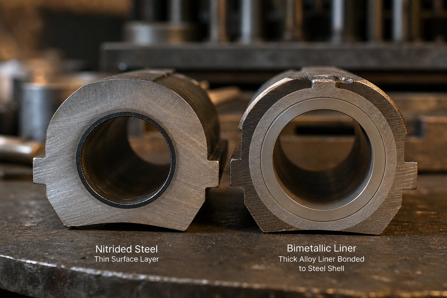
A nitrided barrel starts as a single piece of alloy steel — typically grades like 38CrMoAlA, Nitralloy 135M, or EN-41B — that is surface-hardened by diffusing nitrogen into the bore at temperatures between 500 and 550 degrees Celsius. The two primary methods are gas nitriding (exposing the bore to ammonia-rich atmospheres in a sealed furnace) and ion nitriding (using plasma discharge in a vacuum to accelerate nitrogen diffusion). Both produce a hard case on the bore surface, reaching 950 to 1100 HV (roughly 65-70 HRC equivalent), while the core retains the toughness of the base steel at around 280-320 HB.
The result is a screw barrel with excellent dimensional stability, good fatigue strength, and solid wear resistance — as long as the resin is relatively gentle. For unfilled commodity polymers like LDPE, HDPE, PP, and standard PS, nitrided barrels routinely deliver five to ten years of reliable service at roughly half the capital cost of more advanced options.
So what's the catch? Case depth. The hardened layer is only about 0.4 to 0.6 mm deep. Once abrasive wear grinds through that shallow shell, the soft core underneath is exposed and wear accelerates dramatically. There is no second line of defense. For processors running glass-filled nylon, mineral-reinforced compounds, or recycled streams with unpredictable contamination, a nitrided barrel can go from stable production to emergency replacement in a matter of months.
The key engineering limitation of a nitrided barrel is its case depth — once abrasive wear penetrates beyond 0.5 mm, the soft core is exposed and wear accelerates rapidly with no recovery.
Ion nitriding offers some improvement over conventional gas nitriding. The plasma process allows better control of the nitrogen diffusion profile, produces a more uniform case with fewer compound layers (the brittle "white layer" that can spall under impact), and permits selective nitriding — masking areas that don't need treatment. However, even the best ion-nitrided bore cannot match the wear depth or alloy flexibility of a bimetallic construction when facing aggressively filled or chemically hostile resins.
Bimetallic Barrel Construction and Alloy Lining Options
When nitriding's thin case isn't enough, bimetallic technology takes a fundamentally different approach. Instead of surface-hardening a single piece of steel, a bimetallic barrel bonds a separate wear-resistant alloy liner to the inside of a high-strength steel shell. The liner is where all the engineering magic happens — and its thickness of 1.5 to 3.0 mm gives three to six times the wear depth of nitrided case hardening.
The bonding process is centrifugal casting. Picture the barrel shell rotating at controlled speed in a furnace at approximately 1100 degrees Celsius while powdered alloy is introduced into the bore. As the barrel spins, centrifugal force drives the molten alloy outward against the inner wall, creating a metallurgical bond between the liner and the shell as everything cools. The result is a composite structure — a tough, pressure-resistant outer body with a hard, chemically tailored inner surface purpose-built to resist your specific wear mechanism.
What makes this approach powerful is that the liner alloy can be tuned to the dominant type of attack your resin creates. Three major alloy families cover the vast majority of injection molding applications:
- Iron-boron alloys: The workhorse choice for abrasive resins. These iron-based alloys achieve high hardness (58-62 HRC) and stand up well to mineral-filled and calcium-carbonate-loaded compounds. They are the standard upgrade when a nitrided barrel is wearing too fast on filled materials.
- Nickel-based alloys (Ni-Cr-B): Engineered for corrosive environments. Resins like PVC, CPVC, fluoropolymers, and flame-retardant compounds release hydrochloric acid, hydrofluoric acid, or other chemically aggressive off-gases during processing. Nickel-chromium-boron liners resist this chemical attack while maintaining reasonable abrasion resistance. For highly corrosive applications, the barrel may also use a nickel-based backing steel or a trimetallic construction to prevent corrosion from attacking the shell from the liner side.
- Tungsten carbide (WC) composites: The premium tier for extreme abrasive wear. Tungsten, titanium, or tantalum carbide particles are suspended in a corrosion-resistant matrix of nickel, cobalt, and chromium. The resulting liner can exceed 65-75 HRC and handles the most punishing applications — high-percentage glass fiber reinforcement, ceramic-filled engineering compounds, and aggressive recycled feedstock. If you're molding 30%+ glass-filled PA66, this is not a luxury; it's the minimum responsible specification.
Why does bimetallic outperform through-hardened barrels? Because wear through a bimetallic liner progresses through a homogeneous alloy with stable hardness, not a steep gradient from hard surface to soft core. The screw and barrel clearance opens slowly and predictably, giving you time to plan maintenance rather than react to sudden failure. And that service life advantage of 3 to 5 times longer in demanding applications is what makes the higher upfront price a smaller number on the total cost ledger.
Screw Surface Treatments and Hard-Facing Technologies
A wear-resistant barrel paired with a soft screw is like locking the front door while leaving the back wide open. Screws and barrels wear as a system — and neglecting the screw side of the equation is one of the most common and costly oversights in plasticizing component selection.
Several treatment and construction strategies protect screw surfaces against the same abrasive and corrosive forces attacking the barrel bore:
- Tool steel screws: Manufactured from high-alloy tool steels (D2, H13, or similar grades), these screws offer significantly higher base hardness and wear resistance compared to standard 4140 or 4340 alloy steel screws. They are a solid mid-tier choice for moderately filled resins where a commodity screw wears too fast but a fully hard-faced design isn't justified by production volume.
- PM (powder metallurgy) steel flights: Powder metallurgy steels like CPM 9V or CPM 10V achieve extraordinary combinations of hardness and toughness by distributing ultra-fine carbide particles uniformly through the steel matrix. Welded onto flight tips as a hard overlay, PM steel flights resist abrasive wear far longer than conventional tool steels — particularly against glass fiber, which acts as a continuous grinding surface against the flight lands.
- Hard-chrome plating: A thin layer of chromium electroplated onto the screw surface. It provides moderate wear resistance and excellent corrosion protection at a relatively low cost. Chrome plating is most effective in corrosive applications (PVC processing, flame-retardant compounds) where chemical attack is a bigger concern than abrasive grinding. Its limitation is thickness — typically only 0.05 to 0.15 mm — which means it wears through quickly under heavy abrasive load.
- Stellite and nickel-based hard-facing: Welded alloy overlays (commonly Stellite 6 or Colmonoy 56) applied to flight tips and root surfaces. These provide excellent protection against both abrasion and corrosion. However, selection must be coordinated with the barrel liner — some screw hard-facing alloys used in combination with carbide-lined barrels can create catastrophic wear from incompatible metal-to-metal contact.
That last point deserves emphasis. Screws and barrels must be specified as a matched pair. A tungsten-carbide-lined barrel paired with the wrong hard-facing alloy on the screw can generate accelerated adhesive wear that destroys both components faster than if you had used commodity materials. Always consult with your component supplier about metallurgical compatibility before mixing material systems.
Cost vs. Performance: The Total Ownership Calculation
The sticker price of a bimetallic screw barrel assembly can run two to three times higher than a standard nitrided unit. That number stops many procurement teams cold — but it's the wrong number to optimize against.
Consider a real-world scenario: a processor running calcium-carbonate-filled PVC on a nitrided barrel replaces it every 12 to 18 months. Each replacement means not just the barrel cost but also the screw removal, installation labor, machine downtime, startup scrap, and lost production hours. A bimetallic barrel on the same line might last 36 to 60 months. Even at double or triple the purchase price, the bimetallic option typically pays back its premium within 18 to 24 months through reduced downtime and scrap alone — before you even factor in more consistent part quality and fewer rejected lots.
Initial purchase price is the wrong KPI for plasticizing components — the right metric is cost per kilogram of in-spec output over the screw barrel's full service life.
The flip side matters equally. Over-specifying a tungsten-carbide bimetallic assembly for clean, unfilled polyethylene processing adds thousands of dollars with zero operational return. A well-made nitrided screw and barrel will deliver a decade of reliable service on virgin commodity resins. The most expensive barrel is the one that doesn't match the job.
| Material Option | Wear Resistance | Corrosion Resistance | Typical Resin Compatibility | Relative Cost Tier |
|---|---|---|---|---|
| Nitrided steel (gas/ion) | Moderate (0.4-0.6 mm case) | Low to moderate | Unfilled PP, PE, PS, ABS | $ (baseline) |
| Bimetallic — Iron-boron alloy | High (1.5-3 mm liner, 58-62 HRC) | Moderate | CaCO3-filled compounds, mineral-filled resins | $$ (2-2.5x nitrided) |
| Bimetallic — Nickel-based alloy (Ni-Cr-B) | Moderate to high | High | PVC, CPVC, fluoropolymers, FR compounds | $$$ (2.5-3x nitrided) |
| Bimetallic — Tungsten carbide composite | Very high (65-75 HRC) | High | Glass-filled PA, PBT; ceramic-filled resins; aggressive recycled streams | $$$$ (3-4x nitrided) |
| Tool steel screw (D2/H13) | Moderate to high | Low to moderate | Moderately filled engineering resins | $$ (vs. standard alloy screw) |
| PM steel flight overlay (CPM 9V/10V) | Very high | Moderate | High-GF compounds, abrasive mineral fillers | $$$ (vs. standard alloy screw) |
| Hard-chrome plated screw | Low to moderate | High | PVC, corrosive compounds, low-abrasion resins | $ (economical treatment) |
| Stellite / Ni-based hard-facing on screw | High | High | Filled and corrosive resins (must match barrel liner) | $$-$$$ (depends on alloy) |
Selecting the right material combination for your screws and barrels is half the equation. The other half — and the one most processors underestimate — is matching that hardware to the specific resin and filler system it will process. A material that performs brilliantly with mineral-filled polypropylene can fail spectacularly with glass-reinforced nylon, not because the metallurgy is wrong in absolute terms, but because the wear mechanism changed and the specification didn't change with it.
How Resin Type Drives Screw Barrel Specification
Here is one of the most expensive mistakes in injection molding: specifying a screw barrel based on machine tonnage and shot size alone, without accounting for what the resin actually demands. The polymer you process is not a passive passenger — it actively dictates the compression ratio, flight geometry, L/D ratio, and barrel metallurgy required to produce a clean, consistent melt. Get the match wrong, and you'll fight melt quality problems and premature wear that no process tweak can fix.
Different resins behave in fundamentally different ways under heat and shear. Some melt gradually across a wide temperature range; others snap from solid to liquid within a few degrees. Some carry abrasive reinforcements that grind metal surfaces; others release corrosive acids that pit and dissolve them. Every one of those characteristics points to a specific injection molding barrel and screw configuration — and ignoring the connection is one of the most common root causes of plasticizing failures across the industry.
Amorphous vs. Semi-Crystalline Resin Requirements
The molecular structure of your resin — whether amorphous or semi-crystalline — changes the energy equation inside the barrel in ways that directly affect screw design.
Amorphous polymers like ABS, polycarbonate (PC), polystyrene (PS), and PMMA soften progressively over a broad temperature window. They don't have a sharp melting point; instead, they gradually transition from glassy to rubbery to fluid as temperature rises. This forgiving melt behavior means a moderate screw compression ratio for semi-crystalline resin standards — typically 2.0:1 to 2.5:1 — handles them well. The gradual softening requires less mechanical energy input, and the wide processing window gives you room to adjust temperatures without risking degradation or unmelts.
Semi-crystalline resins are a different animal entirely. Nylon (PA6, PA66), POM (acetal), PBT, and polypropylene store energy in tightly ordered crystalline regions that resist melting until a specific temperature threshold is crossed. Once that threshold hits, the transition from solid to liquid is abrupt and narrow. The practical consequence? You need significantly more shear energy and heat to break through those crystalline structures. That translates directly to higher compression ratios — often 3.0:1 to 3.5:1 — and longer L/D ratios in the 22:1 to 26:1 range to ensure every pellet fully melts before reaching the metering zone.
Underestimate the energy requirement of a semi-crystalline polymer, and unmelts will plague your process. Overestimate it — running an aggressive compression ratio on a gentle amorphous resin — and you'll overshear the melt, generating excess heat that causes splay, degradation, and dimensional instability.
Processing Filled and Reinforced Compounds
Adding glass fibers, mineral fillers, or carbon reinforcements to a resin doesn't just change part performance — it fundamentally redefines what the screw barrel must survive. Every pellet of glass-filled nylon entering the feed throat carries thousands of microscopic abrasive particles that grind against flight tips, barrel bore, and non-return valve surfaces with each screw rotation.
Specifying a screw barrel for glass filled nylon, for example, is not optional customization — it is a survival decision for the equipment. The baseline requirements include:
- Barrel material: Bimetallic construction with an iron-boron or tungsten carbide liner. Standard nitrided barrels lose bore diameter at an accelerated rate when exposed to glass or mineral abrasion, sometimes wearing through the case layer within months.
- Screw flights: Hardened flight tips — PM steel overlays (CPM 9V or 10V) or Stellite hard-facing — to resist the continuous grinding action of reinforcement fibers against the flight lands.
- Compression ratio: Moderate, typically 2.5:1 to 3.0:1, balancing the need for thorough melting against the risk of excessive fiber breakage that reduces mechanical properties in the final part.
- Mixing elements: Distributive designs preferred over aggressive dispersive mixers, because high-shear dispersive elements tend to break long glass fibers into short fragments, undermining the very reinforcement you're paying for.
Mineral fillers like calcium carbonate and talc present a subtly different challenge. While less aggressively abrasive than glass fiber, they concentrate wear at the compression zone transition where the solid bed is compacted hardest against the barrel wall. High-loading percentages (30-40% filler by weight) can turn even a moderate resin into a barrel-eating compound. As a practical industry guideline, tungsten alloy barrel linings and screw hard-facings offer the strongest protection against abrasive wear from gritty reinforcements and hard particles.
Handling Shear-Sensitive and Heat-Sensitive Polymers
Not every resin punishes equipment through abrasion. Some destroy themselves — and your parts — if the screw design delivers too much shear or allows too much residence time.
PVC is the classic example. During processing, PVC releases hydrochloric acid (HCl) as a byproduct of thermal degradation. An injection screw design for PVC must limit both shear intensity and material residence time to minimize acid generation. That means:
- Shallow compression ratios: Typically 1.5:1 to 2.0:1 — far lower than semi-crystalline resins. The goal is gentle melting with minimal mechanical energy input.
- Shorter L/D ratios: Around 18:1 to 20:1, reducing the time resin spends inside the heated barrel.
- Corrosion-resistant materials: Nickel-based barrel liners and hard-chrome-plated screws to withstand the HCl attack. Standard nitrided or iron-boron components will pit and corrode rapidly in PVC service.
- Streamlined flow paths: No dead spots in the screw tip, non-return valve, or nozzle where material can hang up and degrade into black specks.
PMMA (acrylic) and certain optical-grade polycarbonates share a related sensitivity — not to corrosion, but to excessive shear heating. These materials demand low-shear screw geometries with generous channel depths and gentle compression transitions to preserve optical clarity and prevent yellow discoloration. Distributive mixing elements work well here; aggressive dispersive sections do not.
Fluoropolymers like PTFE and FEP push both sensitivities to the extreme. They release hydrofluoric acid during processing, which is far more aggressive than HCl. As one resin manufacturer makes clear, all equipment surfaces contacting the melt must use nickel-based alloys such as Hastelloy, Inconel, or Monel — standard chrome plating is explicitly not recommended because even small chips or cracks in the plating allow acid to attack the underlying steel.
Resin-to-Screw Barrel Matching at a Glance
- PP, PE (unfilled): GP metering screw, 2.0-2.5:1 compression, 20:1 L/D, nitrided barrel. Low cost, long service life.
- ABS, PS, SAN (amorphous commodity): GP metering screw, 2.0-2.5:1 compression, 20:1 L/D, nitrided barrel. Moderate shear tolerance, wide processing window.
- PA6, PA66, PBT, POM (semi-crystalline engineering): Barrier or high-compression GP screw, 3.0-3.5:1 compression, 22:1-26:1 L/D, bimetallic barrel (iron-boron minimum). Higher energy input required for crystalline melting.
- Glass-filled PA, PBT, PPA (abrasive engineering): Barrier screw with hardened flights (PM steel or Stellite), 2.5-3.0:1 compression, 22:1-24:1 L/D, bimetallic barrel (tungsten carbide composite for high-GF percentages). Fiber preservation requires moderate shear.
- PVC, CPVC (shear- and heat-sensitive, corrosive): Low-compression metering screw, 1.5-2.0:1 compression, 18:1-20:1 L/D, nickel-alloy bimetallic barrel with chrome-plated screw. Minimal residence time, streamlined flow paths.
- PMMA, optical PC (shear-sensitive, clarity-critical): Low-shear GP or barrier screw with distributive mixer, 2.0-2.5:1 compression, 20:1-22:1 L/D, nitrided or bimetallic barrel. Gentle melting preserves optical properties.
- Fluoropolymers (PTFE, FEP — extreme corrosion): Specialized low-compression screw, nickel-alloy barrel and screw (Hastelloy/Inconel), matched CTE between screw and barrel to prevent binding at processing temperatures.
Mismatching any of these parameters — running a high-compression screw on PVC, pairing a nitrided barrel with glass-filled nylon, or processing fluoropolymers through chrome-plated equipment — creates a failure mode that no process parameter adjustment can reverse. The damage is metallurgical and cumulative, and it shows up as accelerating wear rates, worsening melt quality, and increasingly frequent unscheduled downtime.
Matching the right hardware to the right resin sets the baseline for equipment longevity. But even a perfectly specified injection screw barrel can wear prematurely if the machine settings pushing it are wrong — and those controllable process variables often get less attention than they deserve.
Machine Settings That Affect Screw Barrel Life
You selected the right metallurgy. You matched the screw geometry to the resin. The hardware is perfectly specified — and yet the screw flights are rounding off twice as fast as expected. What went wrong? In most cases, the answer isn't the equipment. It's the process parameters driving it.
Screw speed, back pressure, and barrel temperature profile are the three settings that most directly determine how quickly your plasticizing components wear. They also happen to be the three settings most frequently treated as "set and forget" values inherited from the last process tech who touched the machine. That disconnect between controllable parameters and component longevity is where some of the most preventable damage occurs.
Screw barrel wear rate is not a fixed property of the hardware — it is heavily influenced by controllable process variables that processors adjust every day.
Screw Speed and Shear Heat Management
Every revolution of the screw does two things simultaneously: it conveys material forward, and it generates shear heat through friction between the polymer, the flight surfaces, and the barrel wall. Faster RPM means more shear energy per unit of time — which sounds beneficial for melting but carries a direct mechanical cost.
Imagine running glass-filled nylon at high screw speed. Each rotation drags abrasive glass fibers across the flight tips and barrel bore at increased velocity, accelerating the grinding action that widens the screw-to-barrel clearance. Doubling the RPM doesn't just double the shear — it can more than double the wear rate because the abrasive contact frequency and energy both increase. For filled and reinforced compounds, injection molding screw speed settings should be kept as low as practical while still achieving full recovery before the mold opens.
Shear heating also raises the actual melt temperature far beyond what the barrel heater displays indicate. As MD Plastics engineering data confirms, two machines with identical barrel temperature setpoints can produce melts differing by 20 to 40 degrees Fahrenheit — purely because of differences in screw RPM and the shear energy it generates. That hidden temperature rise has real consequences:
- Thermal degradation: Excessive screw speed on heat-sensitive resins like PVC or PMMA generates localized hot spots in the melt channel. The polymer degrades, releases corrosive byproducts, and attacks flight surfaces and barrel bore from a chemical angle — compounding the mechanical wear already underway.
- Reduced residence time: Higher RPM recovers the shot faster, which sounds efficient but shortens the time available for complete melting and homogenization. The result can be unmelted particles reaching the non-return valve, where they wedge against seating surfaces and accelerate valve wear.
- Unnecessary energy input: If the heater bands are already supplying sufficient thermal energy, cranking up the screw speed adds redundant shear heat that the barrel cooling system must then fight against — wasting energy and destabilizing the temperature profile.
A practical rule of thumb: set the screw speed so that recovery completes two to three seconds before the mold opens. This approach, supported by Avient's processing guidelines, minimizes unnecessary residence time at temperature while limiting shear to only what the process actually requires. If recovery finishes too early, reduce RPM rather than extending the idle dwell time with the melt sitting hot inside the barrel.
Back Pressure Effects on Melt Quality and Wear
Back pressure is the force applied against the screw's rearward movement during recovery. Think of it as resistance — a controlled drag that slows the screw's retreat as it accumulates melt in front of the non-return valve. It is arguably the most misunderstood setting on the machine, and getting it wrong creates problems on both ends of the spectrum.
Too little back pressure allows the screw to retract too freely. The melt in front of the screw tip is loosely packed, trapping air between poorly compressed polymer layers. The immediate symptoms are splay, voids, and inconsistent shot weight from cycle to cycle. As Fimmtech's research on backpressure optimization demonstrates, insufficient pressure produces wide shot-weight variation because the melt density changes unpredictably from shot to shot. Weight equals volume multiplied by density — and if the density fluctuates, dimensional consistency in your parts is impossible regardless of how tightly you control injection and pack.
Too much back pressure pushes in the opposite direction. Excessive resistance forces the screw to work harder during recovery, increasing shear stress on every flight surface and driving melt temperatures above the target window. For abrasive compounds, that extra mechanical energy translates directly into accelerated flight edge wear. For heat-sensitive materials, it means thermal degradation, discoloration, and potentially corrosive byproducts attacking the barrel bore.
The optimization approach is straightforward. Mold a series of injection-only shots — no pack-and-hold phase — at progressively increasing back pressure settings. Weigh ten consecutive shots at each setting and calculate the range between the heaviest and lightest. The back pressure that produces the narrowest weight range is your sweet spot: the point where melt density is most consistent without excessive shear. In the study published by Plastics Technology, this optimization produced a usable window between 500 and 700 psi of plastic pressure, with 600 psi delivering the tightest consistency.
One additional detail matters for screw barrel longevity. If splay persists after optimizing back pressure, a modest increase beyond the initial optimum is acceptable — but always monitor the melt temperature with a probe rather than relying on barrel zone displays. The back pressure injection molding screw interaction generates shear heat that the controller cannot see, and chasing splay with ever-higher pressure without measuring actual melt temperature is a reliable path to premature wear.
Optimizing Barrel Temperature Profiles
Barrel temperature is where most processors start when troubleshooting melt problems — and ironically, it is where the least control over actual melt temperature resides. Heater bands heat steel, not polymer. The actual temperature the resin experiences inside the screw channel is governed primarily by shear, screw design, back pressure, and residence time. The barrel profile's job is to support the melting process, not to drive it single-handedly.
Three primary barrel temperature profile optimization strategies exist, and choosing the wrong one for your resin creates problems that no screw speed or back pressure adjustment can fix:
- Standard ramp (ascending rear-to-front): The most common profile. Feed zone temperatures stay low — typically 120 to 150 degrees Celsius — to prevent premature pellet melting and feed throat bridging. Temperatures increase progressively through the compression and metering zones, reaching the target melt temperature at the nozzle. This works well for PP, PE, PS, ABS, and most general-purpose resins with predictable melting behavior.
- Flat profile (uniform across zones): All barrel zones run at or near the same setpoint. This is the preferred strategy for shear-sensitive polymers like PC and PMMA, where the barrel simply needs to maintain a stable thermal environment and let the screw's mechanical shear do the primary melting work. Running a ramp profile on these materials risks overheating the front zones and creating thermal degradation, yellowing, or drool.
- Reverse profile (descending rear-to-front): Zone 1 runs hottest, with temperatures stepping down toward the nozzle. This unconventional approach helps high-viscosity resins and moisture-sensitive nylons (PA6, PA66) by improving solid conveying in the feed section — hotter pellet surfaces grip the barrel wall better and resist slippage. Reverse profiles also help with glass-filled nylons, where high viscosity and abrasive content make consistent feeding a persistent challenge.
The screw barrel wear rate factors hiding in these profiles are subtle but real. A feed zone set too hot softens pellets prematurely, causing them to smear against the barrel wall instead of being conveyed forward. That smeared layer acts as an insulating film, forcing the screw to work harder and generating localized wear at the feed section flights. Conversely, a metering zone set too cold produces viscosity spikes that increase injection pressure requirements, stressing the non-return valve and screw tip under loads they weren't designed to sustain continuously.
Perhaps the most damaging mistake is assuming the displayed barrel temperatures equal the actual melt temperature. As thermal analysis from engineering studies confirms, heater band readings reflect barrel wall conditions — not polymer conditions inside the screw channel. If you're adjusting zone temperatures to chase a defect without probing the actual melt at the nozzle, you're tuning blind. The real fix often lies in adjusting RPM or back pressure to control shear-generated heat, not in nudging heater setpoints up or down by five degrees.
These three parameters — screw speed, back pressure, and temperature profile — form a triangle of interdependent controls. Change one, and the other two shift in response. Optimizing them together, rather than tweaking each in isolation, is what separates processors who get predictable equipment life from those who replace components on an emergency schedule. But even optimized settings can't prevent all wear — and knowing how to measure, monitor, and respond to the wear that does occur is what keeps a well-specified, well-run assembly producing consistent parts for as long as possible.
Wear Monitoring and Maintenance Best Practices
Optimized process settings slow the clock on wear, but they never stop it entirely. Every cycle grinds a few more microns off the flight tips, opens the barrel bore a fraction wider, and edges the non-return valve closer to the point where it no longer seals. The difference between processors who plan maintenance and those who react to emergencies comes down to one discipline: measuring wear before it announces itself through defective parts.
The problem? Most plants don't measure at all. They run until shot weight drifts, recovery time stretches, or scrap rates spike — and by then, the damage has compounded into a far more expensive repair. Injection screw barrel wear measurement is not complicated, but it does require the right tools, a consistent procedure, and a clear framework for interpreting the numbers.
Measuring Screw and Barrel Wear Accurately
You can't assess what you don't measure, and eyeballing a pulled screw tells you almost nothing about actual clearance conditions. Accurate wear assessment requires two instruments and a disciplined procedure.
Measuring the screw: The critical dimension is the flight outer diameter (OD). A standard outside micrometer handles this, but technique matters. As Adams Engineers recommends, place a parallel test bar spanning two adjacent flights and measure across the bar and the opposite flight land. This bridges the channel gap and gives a true OD reading rather than a misleading measurement taken across a single flight edge. Record the flight OD at every other flight along the full screw length, and measure the root diameter between every other flight through the feed and metering sections.
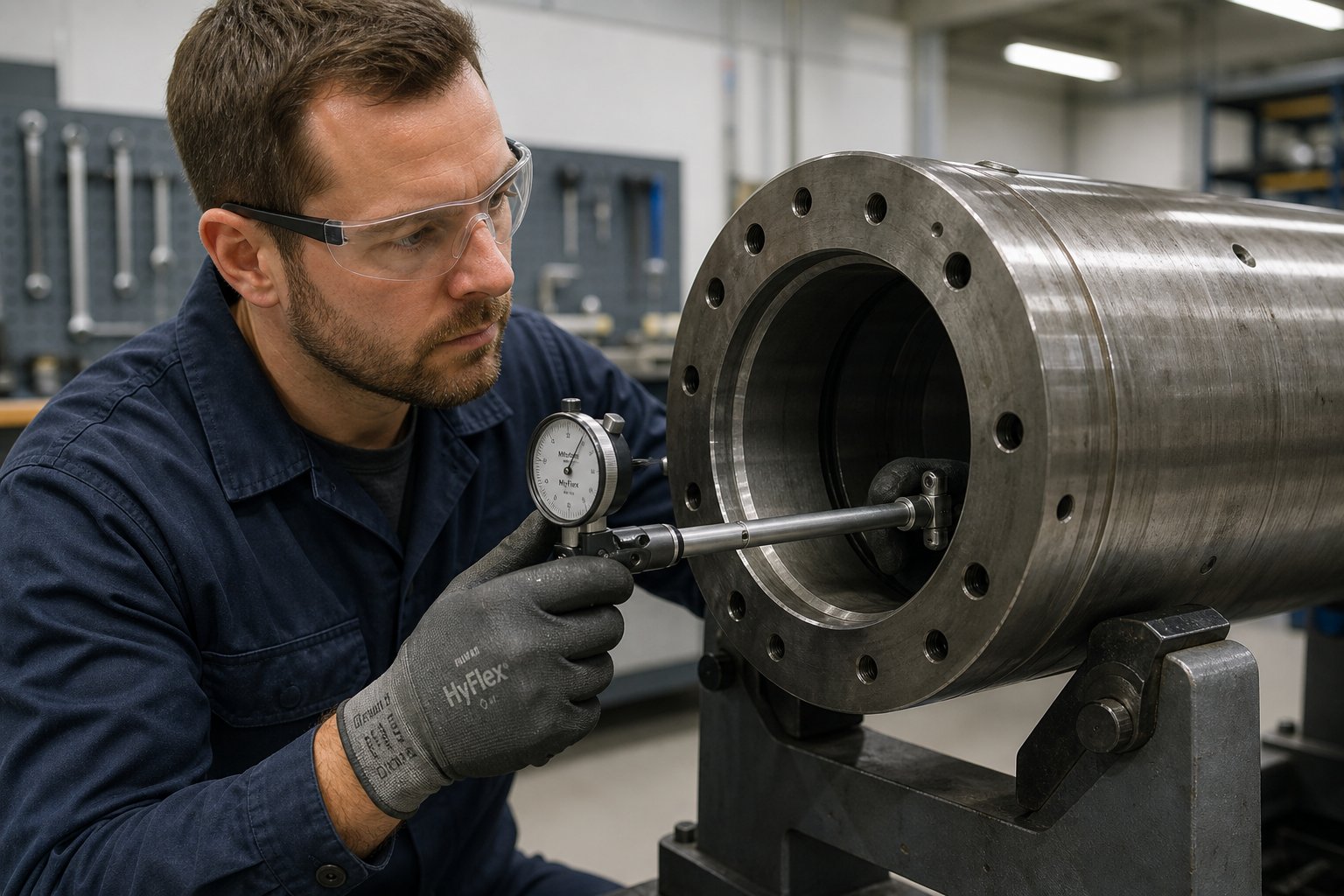
Measuring the barrel: Compared with the screw, a barrel bore gauge inspection procedure is relatively straightforward — but precision is non-negotiable. Using a dial bore gauge calibrated to the nominal barrel diameter, take measurements every two to three inches down the barrel length. That tight spacing picks up localized wear zones that wider intervals miss. Record readings at two perpendicular axes (typically 0 and 90 degrees) at each location to detect ovality — uneven bore wear that signals alignment issues between the screw and barrel.
Interpreting the clearance delta: Subtract the screw flight OD from the barrel bore ID at each corresponding position. The resulting diametral clearance is the number that matters. Compare it against the OEM specification — typically printed on the original component documentation or available from the manufacturer. The SPI Dimensional Guidelines provide industry-standard reference values for when clearance has exceeded serviceable limits. As a general principle, when diametral clearance reaches approximately twice the original specification, plasticizing efficiency begins to degrade noticeably, and replacement planning should begin.
Here is a step-by-step procedure you can hand directly to your maintenance team:
- Purge the barrel completely using an appropriate purging compound, then retract and remove the screw while the barrel is still warm enough for residual resin to release.
- Clean the screw using brass gauze or a soft wire brush while it is still hot — but avoid excessive temperatures that could cause warpage. Allow it to cool to room temperature on a clean, flat surface before measuring.
- Check screw straightness by rolling it on a granite surface table or a set of V-blocks. Watch for wobble or daylight underneath the screw body. If bent, use feeler gauges to quantify the deviation.
- Measure flight OD with an outside micrometer and parallel test bar at every other flight, recording values on a data sheet keyed to flight number and zone (feed, compression, metering).
- Measure root diameter between every other flight through the feed and metering sections. Record values alongside the flight OD data.
- Inspect the screw visually for flight edge rounding, scoring, pitting, cracks, and washout on the root surface. Examine the nose threads and shank for galling or damage.
- Clean the barrel bore with brass gauze after the screw is removed, allowing it to cool to room temperature.
- Measure barrel bore ID with a calibrated dial bore gauge at two-to-three-inch intervals, recording readings at two perpendicular axes per location.
- Inspect the feed throat area visually for cracks, washout spots, and deformation. The bore should also be examined for visible scoring or corrosion — most wear typically concentrates near the middle of the barrel where polymer melting generates the highest abrasive contact pressure.
- Calculate diametral clearance at each position by subtracting screw flight OD from barrel bore ID. Compare values against OEM specifications and previous measurements to establish a wear trend.
Inspection Intervals and Wear Indicators
Calendar-based maintenance schedules — "inspect every six months" — are a poor match for plasticizing components. A machine running three shifts on glass-filled nylon accumulates wear at a completely different rate than a single-shift press molding unfilled polypropylene. Tying inspection intervals to shot count or run hours gives you a measurement cadence that actually reflects mechanical reality.
For unfilled commodity resins processed through properly specified nitrided components, inspection intervals of every 3,000 to 5,000 run hours are generally sufficient to catch developing trends. For filled engineering compounds or corrosive materials, shorten that interval to every 1,500 to 2,500 run hours — or sooner if process indicators suggest accelerating wear. The goal isn't to catch a crisis; it's to build a wear profile over time that lets you predict when clearance will reach the replacement threshold and plan the changeover during scheduled downtime rather than during a production emergency.
Between formal measurement intervals, your press operators can watch for screw flight wear indicators that signal developing problems without pulling the screw:
- Increasing recovery time: If the screw takes progressively longer to build a full shot at the same RPM and back pressure, clearance has widened enough that melt is leaking backward past the flights instead of being conveyed forward.
- Cushion position drift: A growing inconsistency in the cushion position from shot to shot — especially when the non-return valve was recently replaced — points to barrel bore wear reducing the screw's ability to maintain a consistent melt seal.
- Declining shot weight: Weigh parts periodically. A gradual downward trend at constant process settings is one of the earliest and most reliable indicators of wear-related leakage.
- Visible flight edge rounding: When you do pull the screw, compare the flight edges in the compression and metering zones against those in the feed section. Sharp, well-defined edges in the feed zone alongside visibly rounded edges downstream confirm abrasive wear is concentrated where melting occurs — exactly as expected.
- Scoring and galling: Longitudinal scratches on the screw root or flight lands indicate metal-to-metal contact — possibly from misalignment, contamination, or a piece of tramp metal that passed through the feed throat. Scoring often appears alongside adhesive wear patterns that are distinct from the uniform polishing of normal abrasive wear.
- Corrosion pitting: Small, irregular craters on the screw surface or barrel bore — especially concentrated in the metering zone — signal chemical attack from degraded resin byproducts. This is common in PVC, fluoropolymer, and flame-retardant compound processing and indicates either insufficient corrosion resistance in the metallurgy or excessive residence time allowing degradation.
Tracking these indicators alongside your measured clearance data creates a complete picture. The numbers tell you how much wear has occurred; the visual indicators tell you what type of wear is dominant and where it is concentrated — information that directly shapes whether you rebuild or replace.
Rebuild or Replace — Making the Right Economic Call
When the measurements confirm that clearance has exceeded serviceable limits, you face a decision that carries significant cost implications in either direction: rebuild the existing components or invest in new ones? The answer depends on the extent of wear, the type of damage, and the economics of your specific production environment.
When rebuilding makes sense:
- Screw hard-facing: If the screw body is straight, the root surface is intact, and only the flight tips show significant wear, welding new hard-face alloy (Stellite, Colmonoy, or PM steel overlay) onto the flight lands restores the OD to near-original dimensions. This is typically cost-effective when the wear is confined to the flight tips and doesn't extend into the root or transition geometry. A rebuilt screw can deliver performance comparable to a new unit at 40 to 60 percent of the replacement cost.
- Barrel relining: Some bimetallic barrel manufacturers offer relining services where the worn liner is bored out and a new alloy liner is centrifugally cast in place. This is economically attractive for large-diameter barrels where the shell itself is expensive and structurally sound. Relining is less practical for smaller barrels where the cost difference between relining and a new bimetallic barrel narrows considerably.
When full replacement is the better investment:
- The screw is bent, cracked, or shows deep washout in the root surface. No amount of hard-facing fixes a compromised core geometry.
- Barrel bore wear is uneven or oval-shaped, indicating alignment problems that will quickly destroy a rebuilt screw. Replace the barrel and correct the alignment before installing a new screw.
- The wear damage extends across all three zones plus the non-return valve. At that point, the cumulative cost of rebuilding every component often approaches or exceeds the price of a matched new assembly — and the new set comes with full OEM tolerances and a warranty the rebuild cannot match.
- You're changing resin families or filler systems. If the next production campaign involves a fundamentally different material — moving from unfilled ABS to 30% glass-filled nylon, for example — rebuilding the old components to their original metallurgy doesn't make sense. Specify new components matched to the incoming material and avoid the accelerated wear that would result from running the wrong metallurgy.
The screw barrel rebuild vs replace decision should never be based on component purchase price alone — factor in downtime cost, rebuild lead time, remaining metallurgical life, and whether the application has changed since the original specification.
Expected service life varies dramatically depending on what you're processing. Unfilled commodity resins running through properly matched nitrided components can deliver many years of production before clearances reach critical thresholds. Heavily glass-filled engineering compounds can push even tungsten-carbide-lined bimetallic assemblies to their limits in a fraction of that time. The variable isn't just the hardware — it's the interaction between hardware, resin, filler loading, and the process parameters discussed in the previous section. Every one of those factors either extends or compresses the useful life of the assembly.
A wear monitoring program doesn't just tell you when components need attention — it tells you why they wore the way they did. And that diagnostic insight is exactly what separates routine maintenance from effective troubleshooting. When shot weight drops, recovery slows, or black specks start appearing in your parts, the measurement history you've built becomes the foundation for identifying root causes quickly rather than chasing symptoms across the entire machine.
Troubleshooting Common Injection Screw Barrel Problems
Measurement data tells you how much wear exists. Troubleshooting tells you what that wear is doing to your parts — and what to fix first. The frustrating reality of injection molding screw barrel troubleshooting is that symptoms rarely point to a single cause. Shot weight drops, and the culprit could be a worn check ring, an enlarged barrel bore, incorrect back pressure, or all three acting together. Black specks appear, and the root cause could live in the barrel, the hot runner, or the operator's shutdown procedure from three days ago.
What separates fast diagnosis from weeks of trial-and-error is a structured framework — one that maps visible symptoms back to their most probable origins inside the plasticizing assembly. The sections below organize the five most common screw barrel problems into exactly that kind of diagnostic map, and the summary table at the end gives your maintenance team a quick-reference tool they can carry to the press.
Diagnosing Wear-Related Performance Decline
Wear doesn't announce itself with a single dramatic failure. It whispers through subtle process shifts that compound over weeks and months until someone finally notices that parts are no longer meeting spec. Here's what to watch for — and where to look when the numbers start drifting.
Declining shot weight is often the first measurable signal. As screw flight OD decreases and barrel bore ID increases, the clearance between them widens. Molten polymer that should be conveyed forward instead leaks backward past the flights during recovery, reducing the volume of melt available for injection. You'll notice the cushion position creeping higher as the machine compensates, and part weights trending downward even though process setpoints haven't changed.
Longer recovery times follow the same mechanical logic. A worn screw loses pumping efficiency because the widened clearance allows more backflow per revolution. The screw must turn more revolutions — or run longer at the same RPM — to build the same shot volume. If recovery time has increased by 10 to 15 percent or more at constant screw speed and back pressure settings, that's a strong indicator of clearance-driven efficiency loss.
The corrective path starts with the measurement procedure outlined in the previous section. Pull the screw, measure flight OD and barrel bore ID, and calculate the diametral clearance at every zone. Compare the results against OEM specifications. If clearance has reached roughly double the original value, plasticizing performance is already degraded and replacement or rebuild planning should begin. Equally important, inspect the check ring, screw tip, and barrel for wear that affects metering stability and non-return sealing — because a worn check ring amplifies the same symptoms and can mask the true extent of barrel wear if both are deteriorating simultaneously.
Solving Melt Quality Issues and Black Specks
When parts come off the press with unmelted particles, color streaks, or dark contamination, the problem lives somewhere in the plasticizing chain — but pinpointing where requires distinguishing between two fundamentally different failure modes.
Unmelts and color streaks point to inadequate melt preparation. The polymer is reaching the non-return valve without being fully plasticized or uniformly mixed. Common culprits include:
- Worn compression zone flights that no longer generate sufficient shear to break down the solid bed against the barrel wall.
- Incorrect screw geometry for the resin — a low-compression screw trying to process a semi-crystalline polymer that demands aggressive melting energy.
- Insufficient back pressure, which allows the screw to retract too freely and packs the shot loosely with poor thermal uniformity.
- A barrel temperature profile that starves the compression zone of the heat support it needs to complete the melt transition.
Corrective actions start with verifying that the screw design matches the resin's melting characteristics. If geometry is correct, check flight wear in the compression and metering zones — rounded flight edges reduce the shear contact area and let solid fragments slip forward. Optimize back pressure and barrel profile as described in the machine settings discussion earlier.
Black specks are a different beast. Those dark particles embedded in your parts are almost always degraded polymer or carbon buildup that formed inside the screw, barrel, or hot runner and eventually broke loose into the melt stream. The injection molding black specks screw barrel connection traces back to several root causes:
- Dead spots: Areas in the screw tip assembly, non-return valve, or nozzle where melt flow stagnates. Polymer trapped in these zones sits at elevated temperature far beyond its intended residence time, degrades into carbonized fragments, and periodically flushes into the flow path.
- Excessive residence time: Running a small shot size in an oversized barrel means the bulk of the melt sits idle at processing temperature for far too long. Thermal degradation begins, and charred material contaminates subsequent shots.
- Inadequate purging: Color or material changeovers that don't fully displace previous resin leave residue clinging to screw flights and barrel walls. That residue degrades over time and appears as specks or streaking in new production runs.
- Overheated barrel zones: A failed thermocouple or a heater band running unchecked can push local barrel temperatures well above the resin's degradation threshold, cooking the polymer against the bore surface.
Fixing black speck contamination requires a systematic approach. Verify that the shot size falls within the recommended 20 to 80 percent of barrel capacity to keep residence time in check. Inspect the screw tip, check ring, and nozzle for dead spots where geometry creates stagnation. Implement purging procedures during every material changeover and after extended downtime. And confirm that every thermocouple is reading accurately — a single drifting sensor can create a localized hot zone that silently cooks resin into carbon deposits for days before the contamination surfaces in parts.
Fixing Feed Zone Bridging and Inconsistent Shots
Feed zone bridging — when material blocks the feed throat and stops the flow of pellets into the screw — is one of the most disruptive problems on any molding floor. It halts production instantly, can create dangerous pressure buildup, and is frequently misdiagnosed. Understanding the two distinct types of bridging, as injection molding expert John Bozzelli explains, is the key to applying the right fix.
- Type 1 (thermal bridging): Individual pellets stick together in the feed throat because the throat temperature is too high. You'll find a clump of mostly unmelted granules loosely bonded — they break apart easily. The fix is straightforward: lower the feed throat water temperature. This type is the less common of the two and is the only type that responds to temperature adjustment.
- Type 2 (backflow bridging): A solid mass of mostly melted plastic blocks the feed throat. This is not caused by excessive throat temperature. Instead, it signals a worn non-return valve, worn screw flights, or an enlarged barrel bore — any condition that allows molten polymer to leak backward during injection, pushing melt all the way into the feed section where it solidifies into a plug. Lowering the feed throat temperature will not solve a Type 2 bridge and can actually make the situation worse. The only real corrective action is identifying and replacing the worn component — check ring, screw, or barrel — that is allowing the backflow.
Feed zone bridging injection molding problems carry a safety concern that many processors underestimate. When a Type 2 bridge seals the feed throat, trapped air between the granules in the feed section has no vent path. Pressure builds until the plug blows out — sometimes violently enough to launch plastic and even the hopper toward the ceiling. If you see pock marks on the ceiling above your presses, you've already experienced this failure mode. Always wear eye protection before inspecting a bridged feed throat.
Inconsistent shot size — parts that swing between slightly short and slightly heavy from cycle to cycle — shares overlapping root causes with both wear-related decline and feed zone issues. The most frequent origin is inconsistent shot size screw wear at the non-return valve. A check ring that no longer seats cleanly allows variable amounts of melt to leak rearward during injection, producing shot-to-shot weight swings that no process adjustment can stabilize. Worn check rings, screw slip, and cushion variation are among the most commonly overlooked machine-condition issues driving dimensional instability.
Test for check ring leakage by removing pack-and-hold pressure and firing a series of injection-only shots. Line them up and compare size and weight. Significant variation confirms leakage. Replace or rebuild the valve assembly, then retest before adjusting any other process parameter.
Diagnostic Quick-Reference Table
| Problem | Symptoms | Root Causes | Corrective Actions |
|---|---|---|---|
| Excessive screw/barrel wear | Declining shot weight; longer recovery times; cushion position drift; gradual increase in injection pressure needed | Widened screw-to-barrel clearance from abrasive or adhesive wear; wrong metallurgy for filler type; excessive screw RPM accelerating abrasion | Measure flight OD and bore ID; compare clearance to OEM spec; rebuild flights with hard-facing or replace assembly; review metallurgy match to resin/filler; reduce screw RPM to minimum practical level |
| Poor melt homogeneity (unmelts, color streaks) | Visible unmelted particles in parts; inconsistent color distribution; streaking in clear or light-colored materials | Worn compression zone flights reducing shear; screw geometry mismatched to resin; insufficient back pressure; barrel temperature profile not supporting melt transition | Inspect compression zone flight condition; verify screw design matches resin melting behavior; optimize back pressure for tightest shot-weight range; adjust barrel profile to support — not replace — shear-driven melting |
| Black specks and material degradation | Dark particles or streaks in molded parts; contamination worsening after downtime or color changes; carbon fragments in purge shots | Dead spots in screw tip, check ring, or nozzle; excessive residence time (undersized shot in oversized barrel); inadequate purging during changeovers; failed thermocouple causing localized overheating | Inspect screw tip and valve for stagnation geometry; verify shot size is 20-80% of barrel capacity; implement purging protocols for every changeover and shutdown; calibrate all thermocouples and check heater band output |
| Inconsistent shot size | Shot-to-shot weight variation; cushion instability; parts alternating between short and flashed; dimensional drift beyond tolerance | Worn check ring or ball check not sealing during injection; barrel bore wear allowing melt leakage past flights; unstable hydraulic pressure or switchover behavior | Test check ring with injection-only shots (no pack/hold) and compare weights; replace valve assembly if variation exceeds acceptable range; measure barrel bore for wear; verify machine hydraulic and control stability |
| Feed zone bridging | Pellet flow stops; hopper empties but screw starves; pressure buildup and potential blowback; intermittent production stoppages | Type 1: Feed throat temperature too high (granules stick). Type 2: Worn check ring, screw, or barrel allows melt backflow into feed section where it solidifies | Type 1: Lower feed throat cooling water temperature. Type 2: Do NOT lower throat temperature — identify and replace worn check ring, screw, or barrel causing backflow. Inspect feed section flights for evidence of molten polymer where only solid granules should exist |
Print that table and tape it to the press. When a symptom appears, trace the row to its root causes and start with the most probable one. The diagnostic value multiplies when you combine this framework with the wear measurement history from your inspection program — trending data tells you whether a problem is developing gradually (normal wear progression) or appeared suddenly (component failure, contamination event, or process change). That distinction alone can cut your troubleshooting time in half and keep you focused on fixing real causes rather than chasing phantom adjustments across the HMI.
Of course, the best troubleshooting is the kind you never have to do. And that starts well before a problem appears — at the moment you specify and source the replacement screw barrel that will carry your next production campaign.
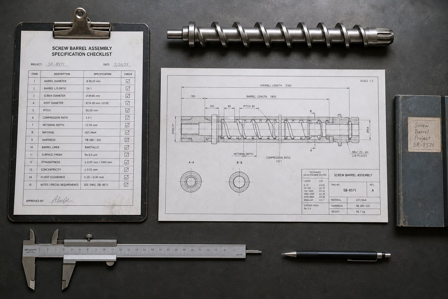
How to Specify and Source the Right Replacement Injection Screw Barrel
Diagnosing the problem is half the battle. The other half — the part that determines whether you repeat the same failure or break the cycle — is specifying the replacement correctly. A surprising number of processors default to ordering a like-for-like replacement of whatever came with the machine originally, regardless of whether the original specification was ever right for the resin, filler, or production demands they're actually running. That reflexive re-order is how mismatched equipment stays mismatched for years, and why the same wear patterns keep showing up on the same press.
Specifying a replacement injection molding screw barrel is not a purchasing task. It's an engineering decision that should account for everything the previous sections covered — resin behavior, filler abrasion, metallurgy, screw geometry, and the process conditions the assembly will face. The checklist below captures the critical questions to answer before you pick up the phone or fill out a quote request.
The Specification Checklist Every Processor Needs
Walk through these steps in order. Each answer narrows the field of appropriate options, and skipping any one of them leaves a gap that can undermine the entire specification.
- Identify your primary resin type and its melting behavior. Is it amorphous or semi-crystalline? Semi-crystalline polymers like PA66 and POM demand higher compression ratios and longer L/D ratios than amorphous materials like ABS or polycarbonate. This single distinction shapes the entire screw geometry.
- Document filler type and loading percentage. Glass fiber, mineral filler, carbon fiber, ceramic microspheres — each carries a different abrasive intensity. A 15% glass-filled compound and a 40% glass-filled compound require fundamentally different barrel metallurgies. Capture the exact grade and percentage, not just "filled nylon."
- Assess corrosive potential. Does the resin or any additive release corrosive byproducts during processing? PVC generates hydrochloric acid. Fluoropolymers release hydrofluoric acid. Flame retardants can produce halogenated gases. If the answer is yes, corrosion-resistant liners and screw treatments move from optional to mandatory.
- Record machine tonnage, bore diameter, and shot size. The replacement must match the machine's mechanical interface precisely — flange dimensions, overall length, feed throat alignment, and bore diameter. Cross-reference the machine OEM's specification sheet and measure the existing barrel rather than relying solely on documentation, since previous replacements may have altered dimensions.
- Define your critical quality requirements. Are you molding optical-grade parts that demand zero black specks and perfect clarity? Medical components with strict contamination limits? Structural parts where fiber length preservation is critical? Each quality driver points toward specific screw designs — distributive mixers for optical work, streamlined flow paths for medical, moderate-shear barrier screws for fiber-reinforced compounds.
- Estimate annual production volume and run schedule. A machine running three shifts on glass-filled resin will consume screw and barrel life at a dramatically different rate than a single-shift press molding unfilled polypropylene. High-volume, high-abrasion applications justify the upfront premium of tungsten carbide bimetallic assemblies. Low-volume runs on gentle materials may never wear through a properly specified nitrided unit.
- Evaluate whether the application has changed since the last specification. If you've switched resin families, added fillers, increased cycle rates, or changed colorant systems since the original components were installed, a like-for-like replacement is the wrong answer. Specify for what you're running now, not what the machine was built to run a decade ago.
- Set a realistic budget — but frame it as cost per kilogram of in-spec output. A cheap replacement that fails in eight months costs more than a premium assembly that lasts three years. As Nordson's engineering team emphasizes, the invoice price of a barrel is just the beginning — the true cost includes downtime, scrap, re-machining, and the quality disruption that a premature failure inflicts on your production line.
Print this list, fill in the answers for every press in your plant, and keep the completed sheets in your maintenance files. When the next replacement is needed, you'll have a specification document ready to hand to your supplier instead of a vague request for "same as last time."
What to Look for in a Screw Barrel Supplier
A correct specification only delivers results if the supplier building the components can execute it. Not every manufacturer handles every application equally well, and the differences between suppliers go far deeper than price. Here's how to evaluate a custom injection screw barrel supplier against the criteria that actually matter for long-term production performance.
- Custom engineering capability: Your resin, filler, part geometry, and cycle time create a unique combination. A supplier that only offers catalog screws in standard geometries cannot optimize for your specific application. Look for partners who design screw profiles — flight depths, compression ratios, barrier configurations, and mixing elements — around your actual processing requirements rather than forcing you into a generic template. Does the supplier ask detailed questions about your resin, filler, quality targets, and current problems? That conversation is a strong signal that engineering support exists behind the sales team.
- Breadth of material options: A supplier limited to nitrided barrels cannot serve a processor running glass-filled nylon any more than a nitrided-only screw can survive 30% mineral filler. Evaluate whether the manufacturer offers the full metallurgical spectrum — from standard nitrided steel for commodity resins through iron-boron bimetallic for moderate abrasion, nickel-alloy liners for corrosive environments, and tungsten carbide composites for the most demanding filled compounds. The same depth should apply to screw treatments: tool steel construction, PM steel flight overlays, hard-chrome plating, and compatible hard-facing alloys. A supplier like NANHAIYA, for example, engineers replacement plasticizing components and custom screw barrels specifically for injection molding operations, offering the material breadth and technical support that maintenance teams need to match hardware to their actual processing conditions.
- Technical support for geometry optimization: The best suppliers don't just build what you order — they help you specify what you should order. If your current screw produces unmelts, a knowledgeable supplier can recommend a barrier flight modification or a mixing element addition that solves the problem at the design stage rather than leaving you to chase it with process adjustments after installation.
- Quality control and traceability: Ask how the supplier verifies inlay composition, bore concentricity, and straightness. As industry analysis from Plastics Technology highlights, the composition of both the backing and the inlay should be documented with traceable metallurgical data. Centrifugal casting quality — uniform thickness, absence of porosity, consistent alloy distribution — is a critical determinant of barrel life that you cannot verify by visual inspection alone. A supplier who provides material certifications and dimensional inspection reports demonstrates the process discipline that separates reliable components from expensive gambles.
- Reasonable lead times for replacement components: A screw barrel failure doesn't wait for a twelve-week delivery schedule. Evaluate whether the supplier maintains inventory of common sizes or can expedite custom orders for emergency replacements. Equally important, ask about their capacity for the full range of bore diameters and lengths your plant requires — including older machines that may no longer be supported by the original OEM.
A quick sanity check: if a supplier quotes you a price without asking what resin you process, what filler content you run, or what quality problems you're trying to solve, they're selling commodity hardware — not engineering solutions. Move on.
Total Cost of Ownership Thinking
The screw barrel total cost of ownership calculation is where procurement thinking and production reality collide. Every maintenance manager has sat in a budget meeting where the conversation centered on unit price — "this barrel costs $4,000, that one costs $9,000, buy the cheaper one." That math ignores every cost that actually matters.
Consider what a premature replacement really costs beyond the component invoice:
- Machine downtime: Pulling and replacing a screw and barrel takes hours — sometimes a full shift or more. Every hour the press sits idle carries a burden rate that includes operator wages, lost output, and overhead allocation. On a high-cavitation mold running automotive parts, a single day of unplanned downtime can exceed the price difference between a nitrided and a bimetallic barrel several times over.
- Startup scrap: Every changeover produces scrap parts during startup — dialing in temperatures, cushion, and transfer position. Replace components twice as often, and you double that startup waste.
- Quality disruption: A worn assembly doesn't fail all at once. It degrades gradually, pushing parts closer and closer to tolerance limits. The reject rate climbs, customer complaints increase, and your quality team spends hours sorting marginal lots instead of running production. That hidden cost never appears on the component purchase order but absolutely appears on the P&L.
- Collateral damage: A poorly manufactured barrel can break during high-pressure injection and damage the screw, tip, end cap, and feed housing — turning a single-component replacement into a multi-component catastrophe. The cheapest barrel on the market becomes the most expensive one if its failure takes out adjacent hardware.
The true cost of a plasticizing assembly is not what you pay for it — it is the total of purchase price, installation downtime, startup scrap, quality losses, and collateral damage divided by the kilograms of in-spec output it produces over its working life.
Frame every sourcing decision through that lens. A bimetallic barrel running three to five times longer than a nitrided unit on abrasive resin doesn't just save on replacement frequency — it eliminates multiple downtime events, multiple startup scrap runs, and the cumulative quality erosion that creeps in during the final months of a worn assembly's life. The processor who calculates cost per kilogram of acceptable output — rather than cost per component — will consistently make better purchasing decisions and run more profitable presses.
Ultimately, the injection screw barrel is not a commodity spare part. It is the plasticizing engine that determines melt quality, shot consistency, and the upper limit of what your mold can produce. Specify it with the same engineering rigor you apply to the mold itself. Source it from a partner who understands your resin, your quality targets, and the wear mechanisms that threaten both. Measure it on total cost of ownership rather than invoice price. Do those three things, and the wear signs you've been missing will become the wear trends you manage — on your schedule, not the machine's.
Injection Screw Barrel FAQs
1. How do I know when my injection screw barrel needs replacing?
Key warning signs include declining shot weight at constant process settings, progressively longer recovery times, cushion position drift between cycles, and parts alternating between short shots and flash. To confirm, measure the screw flight outer diameter with a micrometer and the barrel bore with a dial bore gauge. When the diametral clearance between them reaches roughly double the original OEM specification, plasticizing efficiency has degraded enough to justify rebuild or replacement planning. Tracking these measurements over time helps you predict replacement timing and schedule it during planned downtime rather than reacting to production emergencies.
2. What is the difference between a nitrided barrel and a bimetallic barrel?
A nitrided barrel is a single steel cylinder with a thin surface-hardened layer (0.4-0.6 mm deep) created by diffusing nitrogen into the bore. It works well for unfilled commodity resins like PE and PP but wears quickly on abrasive or corrosive materials once the shallow case is breached. A bimetallic barrel bonds a separate alloy liner (1.5-3.0 mm thick) to the inside of a steel shell via centrifugal casting, providing three to six times the wear depth. Liner alloys can be tailored to specific threats — iron-boron for abrasive fillers, nickel-based alloys for corrosive resins, or tungsten carbide composites for extreme conditions. Although bimetallic barrels cost two to four times more upfront, they often deliver a lower total cost of ownership on demanding applications through significantly extended service life and reduced downtime.
3. What causes black specks in injection molded parts from the screw barrel?
Black specks are typically degraded polymer or carbon fragments that formed inside the plasticizing assembly and broke loose into the melt stream. Common root causes include dead spots in the screw tip or non-return valve where material stagnates and thermally degrades, excessive residence time from running a small shot size in an oversized barrel, inadequate purging during color or material changeovers, and failed thermocouples causing localized overheating. To address the issue, inspect the screw tip and check ring for stagnation points, verify the shot size falls within 20-80% of barrel capacity, implement thorough purging protocols, and calibrate every thermocouple to prevent undetected hot zones. Suppliers like NANHAIYA offer custom screw barrel designs with streamlined flow paths that minimize dead spots and reduce degradation risk.
4. How does resin type affect injection screw barrel specification?
Resin characteristics directly dictate screw geometry, compression ratio, L/D ratio, and barrel metallurgy. Semi-crystalline polymers like nylon and POM require higher compression ratios (3.0-3.5:1) and longer L/D ratios to deliver enough energy for melting their crystalline structures, while amorphous resins like ABS and PC process well with moderate 2.0-2.5:1 compression. Glass-filled compounds demand bimetallic barrels with hardened screw flights to resist abrasive wear from reinforcement fibers. Shear-sensitive materials like PVC need low-compression screws, short L/D ratios, and corrosion-resistant nickel-alloy barrel liners because they release hydrochloric acid during processing. Mismatching any of these parameters to the resin creates cumulative metallurgical damage that no process adjustment can reverse.
5. Should I rebuild or replace a worn injection screw barrel?
The decision depends on the extent and type of damage, not just the component price. Rebuilding makes sense when a screw body is straight with intact root surfaces and only the flight tips show significant wear — hard-facing can restore the OD at 40-60% of replacement cost. Barrel relining is viable for large-diameter bimetallic units where the shell is structurally sound. Full replacement is the better investment when the screw is bent or cracked, the barrel bore is oval-shaped indicating alignment issues, wear extends across all zones plus the non-return valve, or you are changing resin families and need different metallurgy. Always factor in downtime cost, startup scrap, rebuild lead time, remaining metallurgical life, and whether the application has changed since the original specification was set.
Written by
Nanhaiya Technical Team
Zhoushan Nanhaiya Plastic Machinery Co., Ltd.
The Nanhaiya technical team supports screw and barrel manufacturing projects through application review, technical communication, custom manufacturing coordination, and production and quality control.
Discuss Your Application
Related Articles
More insights on screw barrel technology and plastics processing.

What Nobody Tells You About Screw Barrel For Plastic Machine Design
Oct 10, 2026
Learn how screw barrel for plastic machine design affects melt quality, throughput, and wear life. Covers geometry, resin matching, troubleshooting, and sourcing.
Read Article
Single Screw Extruder for Sheet: Stop Guessing, Start Specifying
Oct 9, 2026
Learn how to specify a single screw extruder for sheet production. Covers screw geometry, resin-specific processing, troubleshooting, and maintenance best practices.
Read Article
PE Pipe Extruder Machine: What Datasheets Won't Tell You
Oct 9, 2026
Learn how a PE pipe extruder machine works, key specs explained, material grade selection, maintenance tips, and buyer guidance beyond the datasheet.
Read ArticleLooking for something else?
Search by material, symptom or product and jump straight to the relevant page.
These are navigation suggestions based on keyword matching — not a quotation, not a delivery commitment, and not a substitute for engineering review. Final specification is confirmed by our engineers against your drawings and processed material.
Need help with screw barrel selection?
Share your machine model, processed material and application. Our team can help with pricing and technical support.