

What an Injection Screw Does Inside Your Molding Machine
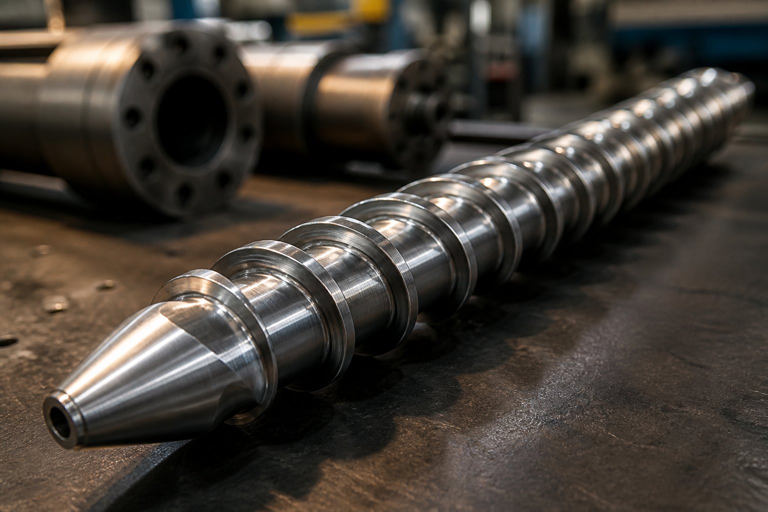
An injection screw is the rotating, helical-flighted component housed inside an injection molding machine barrel. Its job is to convey, compress, melt, and meter polymer resin before pushing it into a mold cavity to form a finished part. Every pellet of raw material that enters the hopper passes through this single component on its way to becoming a product, making it the most influential variable governing melt quality, cycle time, and part consistency.
What Is an Injection Screw and Why Does It Matter
Imagine a component that has to perform two completely different mechanical roles within the same cycle. During the plasticating phase, often called recovery, the screw rotates inside a heated barrel. Friction between the flights, the resin, and the barrel wall, combined with conducted heat from external band heaters, transforms solid pellets into a homogeneous molten pool. The screw simultaneously conveys material forward, compresses it to expel trapped air, and meters a precise volume of melt in front of its tip.
Then the role shifts entirely. During injection, the screw stops rotating and drives forward axially, acting as a hydraulic plunger. This forward stroke pushes the accumulated melt through the nozzle and into the mold cavity under high pressure. The speed, pressure, and volume of this stroke directly control fill pattern, packing density, and ultimately the dimensional accuracy of every molded part.
This dual function, rotating plasticator and reciprocating plunger, is what separates an injection screw from other plasticating devices. It also explains why even small mismatches between screw design and resin behavior can cascade into serious quality problems.
Who Needs to Understand Injection Screw Fundamentals
If you run an injection molding factory trying to optimize part quality, you need this knowledge. If you are a maintenance engineer chasing inconsistent shot weights or unexplained burn marks, screw fundamentals are where diagnosis starts. And if you are a machine rebuilder specifying replacement plasticizing components, selecting the wrong geometry can erase every other investment you make in a rebuild.
The injection screw touches every pellet of resin that becomes a finished part, making it the single most critical variable a processor can control.
Quality-management research consistently shows that many molding operations lose 10-15% of operating costs to poor quality, including scrap, rework, and unplanned downtime. A significant share of those losses traces back to the plasticizing system, and at the center of that system sits the screw.
Yet most failures do not begin with a worn flight or a cracked tip. They begin much earlier, at the selection stage, when the wrong screw design, compression ratio, or material specification is chosen for the application. Understanding why requires a closer look at the screw's physical anatomy: the three functional zones that control how resin moves, melts, and stabilizes before it ever reaches the mold.
Injection Screw Anatomy and Geometry Explained
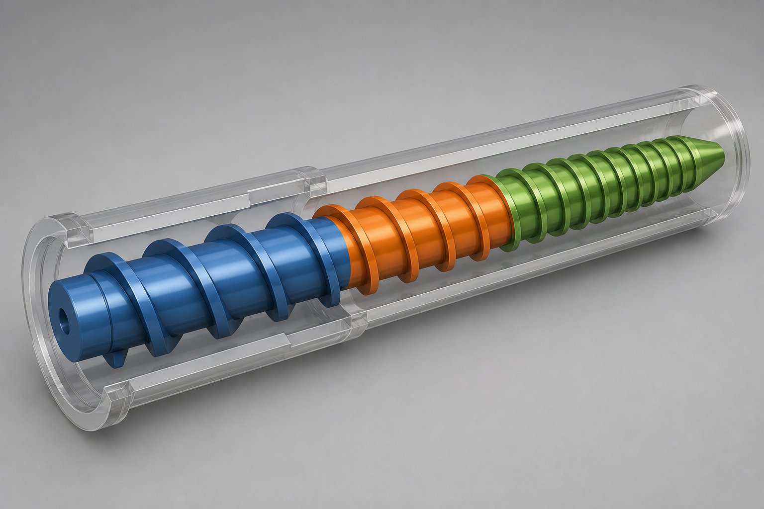
Every injection screw, regardless of brand or barrel diameter, shares a common structural blueprint. Three distinct functional zones run along its length, and each one handles a specific stage of the plasticating process. Understanding what happens inside these zones, and how a handful of geometry parameters tie them together, is essential for anyone diagnosing melt-quality issues or specifying a replacement screw.
The Three Functional Zones of an Injection Molding Screw
Picture the screw as a journey that raw pellets take from the hopper to the melt pool. That journey passes through three stages, each engineered to accomplish a different task.
Feed zone. This is where solid pellets enter the barrel. The channel between the screw flights is at its deepest here, creating maximum volume to accept incoming resin. The deep channel conveys solids forward while friction between the pellets, the barrel wall, and the screw surface begins to generate heat. According to widely referenced general-purpose screw proportions, the feed zone typically occupies about 50 percent of the total flighted length, giving the resin ample time to compact and preheat before melting begins in earnest.
Transition zone (compression zone). Here, the channel depth gradually decreases along the screw's length. This shrinking space compresses the resin, squeezing out trapped air and forcing the material against the heated barrel wall. The combination of barrel-wall conduction and intense shear energy does the heavy lifting of melting. Most of the solid-to-liquid transformation occurs in this zone, which typically spans roughly 25 percent of the flighted length.
Metering zone. The final section features a shallow, uniform channel depth. Its job is to homogenize the melt, ensuring consistent temperature and viscosity throughout, while building the pressure needed to push material through the non-return valve and into the mold. It also accounts for approximately 25 percent of the flighted length. When this zone is well-matched to the resin, you'll notice stable shot weights and uniform color dispersion cycle after cycle.
Key Geometry Parameters and How They Interact
Many processors evaluate injection molding screw geometry parameters in isolation: a flight depth here, a pitch value there. In reality, these dimensions form an interconnected system. Changing one affects the behavior of every other.
Consider flight depth and channel depth. They sound similar, and in many contexts they are used interchangeably, but channel depth specifically describes the radial distance from the screw root to the flight tip, determining how much resin the channel can hold. Reduce it in the metering zone and you increase shear rate and pressure generation. Increase it in the feed zone and you boost solids-conveying capacity. The ratio between these two depths is the compression ratio, a parameter so influential it deserves its own section later in this article.
Pitch and helix angle control how far material advances with each rotation. A square-pitch screw, the most common design, has a pitch equal to the screw diameter and a helix angle of approximately 17.66 degrees. Flight width, typically about one-tenth of the screw diameter in standard designs, affects the bearing surface that pushes resin forward and also influences the amount of shear applied to the melt film.
The table below shows how these parameters relate to one another and what each one controls in terms of melt quality and throughput.
| Geometry Parameter | Definition | Typical Range (GP Screw) | Effect on Processing |
|---|---|---|---|
| Channel Depth (Feed Zone) | Radial distance from screw root to flight tip in the feed section | Varies by diameter (e.g., 5-9 mm for a 60 mm screw) | Governs solids-conveying capacity, residence time, and overall throughput |
| Channel Depth (Metering Zone) | Same measurement in the metering section | Shallower than feed zone; set by target compression ratio | Controls shear rate, melt homogeneity, and pressure generation |
| Pitch (Lead) | Axial distance the flight advances in one full turn | Equal to screw diameter (square pitch) | Determines conveying rate per revolution and material advance speed |
| Helix Angle | Angle of the flight relative to a plane perpendicular to the screw axis | ~17.66 degrees for square pitch | Influences drag-flow efficiency and pressure-flow balance |
| Flight Width | Width of the flight land measured along the screw axis | ~1/10 of screw diameter | Affects shear on melt film, leakage flow over the flight, and wear surface area |
When you read screw specifications, resist the urge to evaluate any single parameter in a vacuum. A deep feed zone paired with a very shallow metering zone creates a high compression ratio that may over-shear heat-sensitive resins. A wide flight width increases the bearing area but reduces the channel cross-section, lowering throughput. Every dimension is a trade-off, and the best screw designs balance them for a specific resin and application.
Understanding L/D Ratio and Its Practical Significance
The length-to-diameter ratio, commonly written as L/D, is one of the first specifications you will encounter on any screw data sheet. It is calculated by dividing the total flighted length of the screw by its nominal diameter. A 60 mm screw with 1,200 mm of flighted length, for example, has an L/D of 20:1.
Most injection molding screws fall in the 20:1 to 24:1 range, while extrusion screws often extend to 30:1 or beyond. The difference exists because an extrusion screw operates continuously at a fixed position, giving it a predictable, constant melting length. An injection screw must reciprocate, meaning its effective melting length changes with every shot. A shorter L/D accommodates that reciprocation while still providing adequate residence time for most commodity and engineering resins.
A longer L/D ratio gives pellets more time under heat and shear, improving melting uniformity and mixing. However, it also increases residence time, which can degrade heat-sensitive polymers. This is why the right L/D is never simply "the longest available" but rather the value that matches the thermal stability and melting characteristics of the primary resin you process.
Geometry alone, though, does not tell the full story. The same three-zone layout and the same L/D ratio can deliver dramatically different results depending on the screw type selected. General-purpose designs handle a wide range of resins, yet they have well-documented limitations when pushed outside their comfort zone, a reality that has driven the development of barrier flights, mixing sections, and other specialized configurations.
Types of Injection Molding Screws From GP to Barrier Designs
A standard three-zone layout can only take you so far. When a general-purpose design runs into a resin or application that exposes its limitations, the solution is not to tweak process settings indefinitely. It is to choose a screw type engineered for the specific challenge. Understanding the progression from basic to advanced designs helps you recognize exactly when an upgrade is worth the investment.
The General-Purpose Metering Screw and Its Limitations
The general-purpose (GP) screw is the default choice shipped with most injection molding machines. Its simple three-zone geometry, deep feed, tapered transition, and shallow metering, handles a broad range of commodity resins like polystyrene, ABS, and polypropylene with acceptable results. For shops running multiple materials on the same press, a GP screw offers versatility without requiring frequent screw changes.
That versatility, however, comes with trade-offs. Semi-crystalline polymers such as nylon and polyethylene have sharp melting points and undergo a significant density change during the solid-to-melt transition. A GP screw's gradual compression often cannot keep pace, leaving unmelted particles in the metering zone. You might also notice poor color dispersion when running masterbatch concentrates, because the GP design provides limited mixing action beyond whatever distributive effect occurs naturally in the metering channel. Heat-sensitive resins like PVC present the opposite problem: the standard compression ratio can generate excessive shear, pushing melt temperatures into the degradation range.
In short, the general purpose vs barrier injection screw debate is not about which is "better" in the abstract. It is about recognizing when the GP design has reached its engineering ceiling for your specific application.
Barrier Screws for Improved Melting Efficiency
Barrier screw design for injection molding addresses one of the GP screw's most persistent weaknesses: uncontrolled solid-bed breakup. In a conventional screw, the solid bed can fracture as it melts, sending chunks of unmelted polymer into the metering zone where conductive heating alone struggles to finish the job. Crystalline polymers are especially prone to this because they resist softening until they reach their melting point and require additional energy to overcome the heat of fusion.
A barrier screw solves this by introducing a secondary flight, the barrier flight, that runs alongside the primary flight through the transition zone. This extra flight creates two separate channels: one for solids and one for melt. As polymer melts against the barrel wall, the liquid flows over the barrier flight into the melt channel, while remaining solids stay trapped until they are fully melted. The result is a far more thermally homogeneous melt exiting the screw, often without needing a downstream mixing section at all.
When should you consider a barrier design? Look for these indicators: you are processing semi-crystalline resins at high throughput, you see unmelted specks or gels in molded parts, or your GP screw requires excessive back pressure to achieve acceptable melt quality. Any of these signals suggests the melting demand has outgrown the conventional three-zone approach.
One important engineering detail: the barrier section's compression rate must closely match the polymer's melting rate. If the solids channel narrows too quickly, trapped material can generate enormous localized pressure, forcing the screw sideways in the barrel and causing accelerated flight wear. Proper barrier screw design balances channel geometry against the specific melting behavior of the target resin.
Mixing Sections and Specialty Screw Designs
Even a well-designed barrier screw may not deliver the level of mixing certain applications require. Color-critical parts, blends containing high percentages of regrind, and formulations with liquid additives all benefit from dedicated mixing elements added to the screw's metering end.
Mixing falls into two categories, and each demands a different hardware solution. Dispersive mixing applies high shear stress to break down agglomerates, undispersed pigment clusters, or the last remnants of unmelted material. The Maddock mixer, sometimes called a fluted mixer, is one of the most widely used dispersive elements. Melt passes over a very narrow clearance between alternating inlet and outlet flutes, experiencing intense shear that also acts as a final melting dam. Distributive mixing focuses on reorienting and recombining flow streams to spread additives or colorants uniformly throughout the melt. Pin-style mixers, pineapple mixers, and Saxton-style elements achieve this by dividing the melt stream many times and recombining it along different paths.
Some designs combine both functions. The Egan-style mixer, for example, uses undercut flights that create multiple high-shear regions along with continuous flow reorientation, delivering strong dispersive and distributive performance in a single element.
Manufacturers in the screw and barrel industry, including those in the Nordson Xaloy product line and various specialized suppliers, offer both standard catalog configurations and custom mixing geometries tailored to specific resins and applications. Choosing the right mixing element starts with identifying your primary problem: are you dealing with undispersed particles (dispersive) or uneven distribution of a well-dispersed additive (distributive)?
Here is a quick reference of the main types of injection molding screws explained by their ideal application:
- General-Purpose (GP) Screw — best for shops processing multiple commodity resins on the same machine with moderate quality requirements.
- Barrier Screw — ideal for semi-crystalline polymers, high-output applications, and any process where unmelted particles are a recurring issue.
- Maddock Mixing Section Injection Screw — used when final melting assurance and dispersive mixing are needed, particularly for pigment-sensitive or glass-filled applications.
- Distributive Mixing Screw (Pin, Pineapple, Saxton) — recommended for color concentrate blending, regrind homogenization, and liquid-additive incorporation.
- Venting Screw — designed with a decompression zone and vent port for resins with high moisture content or volatile off-gassing, eliminating the need for pre-drying in some cases.
- Low-Compression Screw — engineered for heat-sensitive materials like PVC and certain acetals, minimizing shear heating to prevent degradation.
Selecting from this range is not a matter of choosing the most sophisticated option. It is about matching the screw's capabilities to the specific demands of your resin, your throughput target, and your quality standard. And that matching process depends heavily on a parameter we have not yet examined in depth: the difference between an injection screw and its close relative, the extrusion screw, a distinction that carries real consequences when ordering replacement components.
Injection Screw vs Extrusion Screw: Key Differences That Affect Your Bottom Line
Both screws are helical, both rotate inside heated barrels, and both melt polymer. From the outside, they can look nearly identical. Yet installing one in place of the other is a fast path to inconsistent parts, wasted resin, and potential mechanical damage. The injection screw vs extrusion screw difference is not cosmetic — it is rooted in fundamentally different operating modes that dictate every aspect of design, from tip geometry to flight layout.
Functional Differences Between Injection and Extrusion Screws
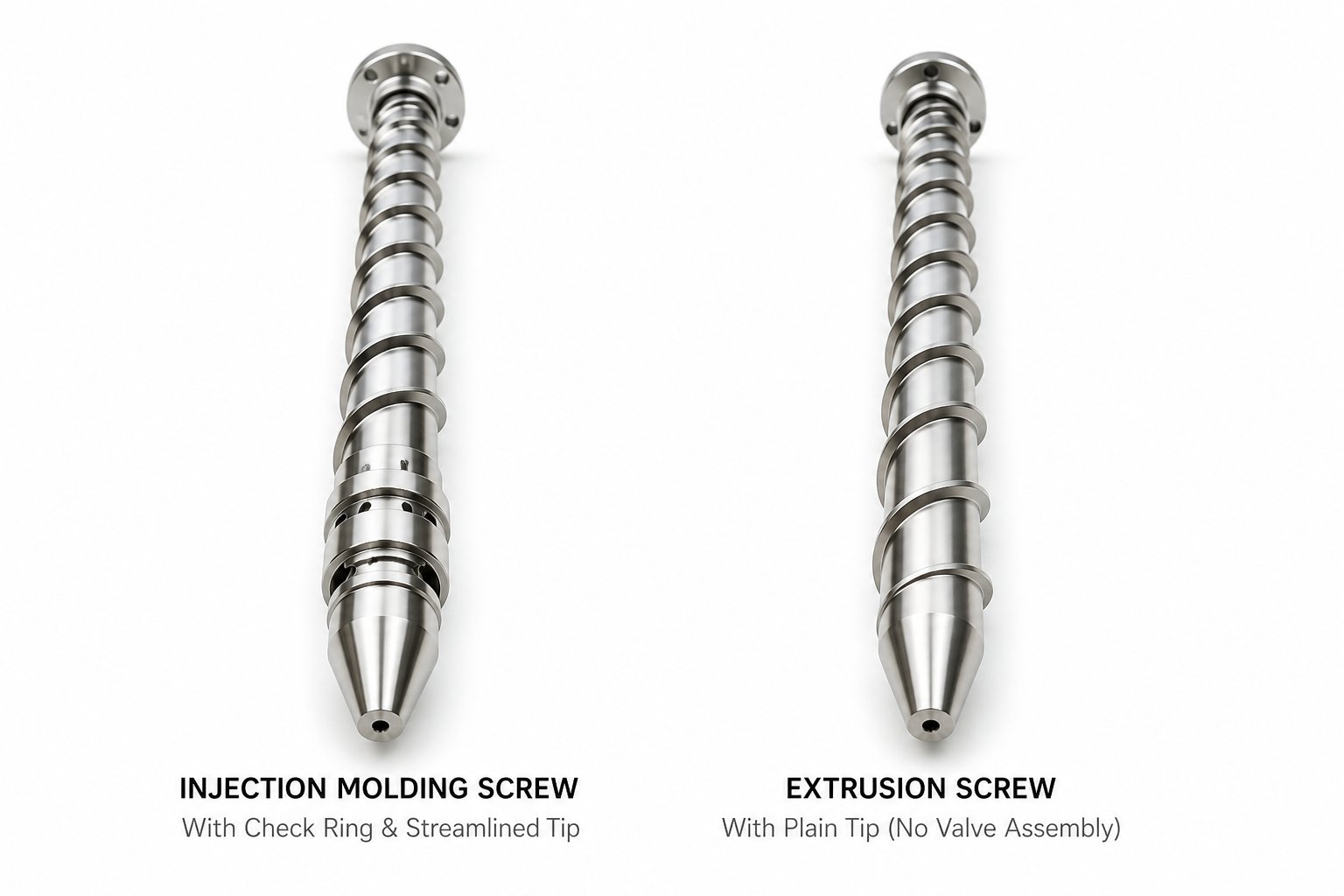
The core distinction is motion. An extrusion screw rotates continuously in a fixed axial position, pushing a steady stream of melt through a die. It never stops, never reverses, and never acts as a plunger. An injection screw, by contrast, must reciprocate. During plasticating recovery, it rotates to melt resin and retreats as the melt pool accumulates ahead of the tip. During injection, it drives forward like a piston, forcing that accumulated shot into the mold cavity.
This reciprocating vs continuous operation has cascading design consequences. Because the injection screw pushes forward to inject, it requires a non-return valve (check ring) at its tip to prevent melt from flowing backward along the flights during the injection stroke. An extrusion screw has no such valve — backflow is simply not part of its operating cycle. The screw-tip geometry also differs: injection tips are streamlined for rapid, high-pressure forward thrust, while extrusion tips transition smoothly into breaker plates and screen packs designed for continuous filtration.
L/D ratio is affected as well. Because the injection screw reciprocates, its effective melting length shortens with every shot. Designers compensate by keeping L/D values moderate, typically 20:1 to 24:1, to ensure adequate melting across the full stroke range. Extrusion screws, operating at a fixed position, can use longer L/D ratios — often 24:1 to 36:1 — to maximize residence time and throughput without worrying about positional variation.
Design and Geometry Variations
The table below lays out the critical parameters side by side. You'll notice that nearly every specification reflects the underlying operational difference between batch metering and continuous output.
| Parameter | Injection Screw | Extrusion Screw |
|---|---|---|
| Primary Function | Batch metering and shot-to-shot consistency | Continuous, steady-state output |
| Axial Motion | Reciprocates (rotates + pushes forward) | Rotates only; fixed axial position |
| L/D Ratio Range | 20:1 to 24:1 | 24:1 to 36:1 (or higher) |
| Compression Ratio Range | Typically 2.0:1 to 3.5:1 | Typically 2.5:1 to 4.5:1 |
| Non-Return Valve | Required at screw tip | Not used |
| Typical RPM Range | Lower; 50-150 RPM during recovery | Higher; 50-300+ RPM continuous |
| Flight Design Emphasis | Optimized for shot-volume accuracy and melt homogeneity within a defined shot size | Optimized for maximum continuous throughput and steady pressure generation |
Extrusion flight designs are often more aggressive in their compression profiles because continuous rotation allows the resin more consistent contact time with the barrel. Injection screws, on the other hand, must balance melting efficiency against the variable effective length created by screw retraction during each recovery stroke.
Why the Distinction Matters for Procurement
Here is where confusion turns costly. When ordering a replacement plasticizing component, specifying only the barrel bore diameter and overall length is not enough. An extrusion screw that physically fits inside an injection barrel will lack a non-return valve seat, have a tip geometry incompatible with injection pressures, and feature flight designs tuned for continuous operation rather than shot-to-shot repeatability. The result? Inconsistent shot weights, melt backflow during injection, poor cushion control, and accelerated wear on both the screw and barrel.
To verify you are ordering correctly, confirm these details with your supplier before approving any replacement:
- Machine type and model — explicitly confirm it is an injection molding machine, not an extruder.
- Non-return valve compatibility — ensure the screw tip is designed for a check ring or ball-check assembly.
- L/D ratio and compression ratio — match these to your resin family and original screw specifications.
- Screw-tip geometry — injection tips must handle rapid axial thrust under high pressure without deflection.
A quick phone call confirming these specifications can prevent weeks of troubleshooting mysterious quality defects that no amount of process adjustment will fix. The screw may fit the barrel, but if it was designed for a different operating mode, it will never deliver the shot-to-shot precision injection molding demands.
Matching the right screw type to the right process is half the battle. The other half lies in a single parameter that governs how aggressively the resin is compressed and sheared as it melts — the compression ratio, and choosing the wrong one for your polymer family introduces an entirely different set of defects.
Compression Ratio and Its Role in Polymer Processing
Every screw type discussed so far, whether general-purpose, barrier, or mixing-enhanced, operates within a set of geometric relationships. Among those relationships, one parameter has an outsized influence on whether resin exits the metering zone as a homogeneous, defect-free melt or as a source of persistent quality headaches. That parameter is the compression ratio, and getting it wrong is one of the most common, yet least discussed, root causes of injection molding defects.
What Compression Ratio Means and How It Is Calculated
The injection screw compression ratio explained in its simplest form is a single division problem. Take the channel depth in the feed zone (H1) and divide it by the channel depth in the metering zone (H2). The result tells you how much the resin's available space shrinks as it travels from the hopper end to the screw tip. A screw with a feed-zone channel depth of 9 mm and a metering-zone depth of 3 mm, for example, has a compression ratio of 3:1.
Sounds straightforward? The calculation is. The implications are not. That ratio determines two things simultaneously: how effectively the screw feeds solid pellets, and how much shear energy it introduces during melting. As Jim Frankland, a veteran screw-design consultant, explains, "the compression ratio has to be established not just to feed enough solid polymer to fill the screw, but also to introduce enough shear heating in the screw to complete melting." In other words, compression ratio is not just a feeding parameter — it is the engine behind the screw's melting capability.
A higher ratio compacts material more aggressively, generating greater shear rates and more frictional heat. A lower ratio treats the polymer more gently, reducing shear energy input at the cost of potentially slower or incomplete melting. The challenge lies in the fact that every polymer has a different ideal balance between feeding capacity and shear-heating demand, which is why a single "standard" compression ratio cannot serve all resins equally well.
Matching Compression Ratio to Polymer Type
Imagine running two very different resins on the same injection molding machine — say, general-purpose polystyrene and glass-filled nylon. Polystyrene is amorphous: it softens gradually over a broad temperature range, has a relatively low melt viscosity, and requires modest energy input to reach processing temperature. Nylon is semi-crystalline: it stays solid until it hits a sharp melting point, undergoes a significant density change during phase transition, and demands substantially more energy to overcome its heat of fusion.
Using the same compression ratio for both is like using the same gear ratio to climb a steep hill and cruise on a flat highway. One will work, the other will struggle.
The table below provides directional guidance on how compression ratio relates to major polymer families. These ranges represent established industry starting points, as referenced in screw-design literature, though the ideal value for any specific application depends on additional variables including shot size, screw RPM, and part geometry.
| Polymer Category | Examples | Typical Compression Ratio Range | Engineering Rationale |
|---|---|---|---|
| Amorphous Resins | PS, ABS, PC, PMMA | 2.0:1 to 2.5:1 (moderate) | Gradual softening over a wide temperature range requires less aggressive compaction; moderate shear energy is sufficient for complete melting |
| Semi-Crystalline Resins | PE, PP, PA (nylon), POM | 2.5:1 to 4.0:1 (higher) | Sharp melting point and significant density change between solid and melt phases demand higher compaction and greater shear-energy input to complete the phase transition |
| Heat-Sensitive Resins | PVC, PVDC, certain TPEs | 1.5:1 to 2.0:1 (low) | Narrow processing window and susceptibility to thermal degradation require minimal shear heating; excessive compression generates corrosive decomposition byproducts |
Notice the wide spread. A PE screw might start at 3:1 as a baseline, while a nylon screw often starts at 4:1 due to its higher crystalline energy requirement. PVC sits at the opposite extreme because even moderate shear heating can push it past its decomposition temperature and release hydrochloric acid gas — a scenario that damages not only the part but also the screw and barrel surfaces.
The best compression ratio for a PVC injection screw, then, is not simply "low." It is specifically low enough to prevent thermal degradation while still providing adequate compaction to convey and melt the resin uniformly. This is why PVC-dedicated screws often pair a low compression ratio with longer transition zones, spreading the compaction work over more screw length so no single point generates a dangerous temperature spike.
How Wrong Compression Ratios Cause Defects
Here is where theory meets the production floor. How compression ratio affects injection molding defects is a direct, cause-and-effect relationship that too many processors overlook when troubleshooting quality issues.
When the compression ratio is too low, the screw does not compact the resin aggressively enough. Insufficient shear heating leaves pockets of partially melted or completely unmelted material in the melt stream. You will see this show up as:
- Unmelted particles or specks embedded in finished parts
- Inconsistent melt temperature from shot to shot, causing dimensional variation
- Poor color dispersion, since unmixed regions pass through the metering zone without adequate homogenization
- Higher reject rates that seem random and resist correction through barrel temperature or back-pressure adjustments
The instinct is often to crank up barrel heater temperatures to compensate, but this only addresses conductive heat transfer. The screw's shear-heating contribution, which accounts for a significant portion of total energy input in most plasticating systems, remains inadequate because the geometry itself is the limiting factor.
When the compression ratio is too high, the opposite problem emerges. The resin is subjected to excessive mechanical shear, converting too much rotational energy into heat within the polymer. The consequences are equally damaging:
- Melt temperatures that overshoot the resin manufacturer's recommended processing window
- Thermal degradation visible as burn marks, brown streaks, or black specks
- Material breakdown releasing gases that cause splay, bubbles, or surface defects on molded parts
- Accelerated screw and barrel wear, especially with corrosive decomposition byproducts from PVC or flame-retardant compounds
Frankland's analysis underscores just how significant this effect can be: assuming the screw is full, a 2:1 compression ratio introduces roughly half as much energy into the polymer as a 4:1 ratio. That is not a subtle difference — it is a doubling of shear energy input that can push a heat-sensitive resin from safe processing into active degradation.
Recycled materials add another layer of complexity. Low-bulk-density regrind may need a deeper feed zone to fill the screw adequately, but pairing that deep feed with a standard metering depth creates a compression ratio that may be too high for the resin's actual melting requirements. Frankland notes that in these situations, feeding and melting should be determined separately, effectively abandoning the idea of a single standard ratio and designing the screw zones independently to match the real material behavior.
The takeaway is practical: if you are chasing intermittent defects that do not respond to process-parameter changes, the compression ratio deserves investigation before you adjust anything else. A screw that physically fits the barrel and visually looks correct can still be fundamentally mismatched to your polymer, and no amount of temperature or speed tweaking will overcome a geometric mismatch built into the hardware itself.
Compression ratio determines how the resin melts. But what happens to the screw as it does that work — the abrasion from glass fibers, the corrosion from aggressive chemistries — depends entirely on the materials and coatings used to construct it. Selecting the right metallurgy and surface treatment is the next critical decision in building a plasticizing system that performs and lasts.
Injection Screw Material and Coating Options That Determine Service Life
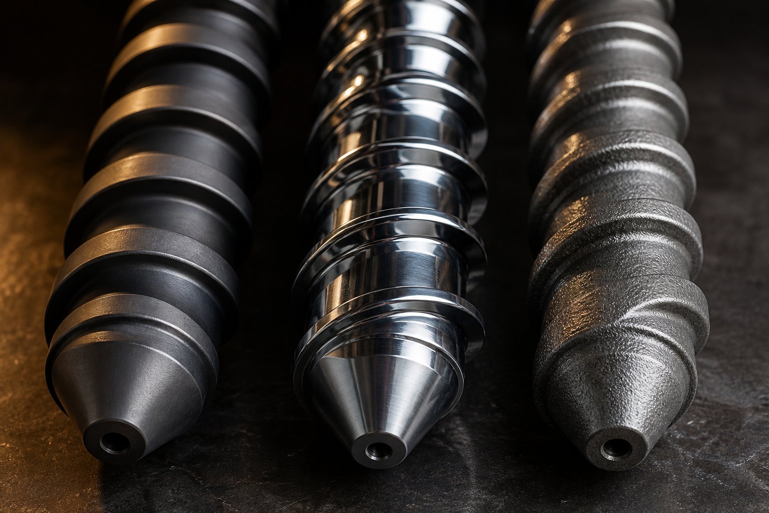
A perfectly designed geometry means nothing if the screw cannot survive the resin running through it. Glass fibers act like microscopic sandpaper against flight surfaces. PVC releases hydrochloric acid that eats into unprotected steel. Flame-retardant compounds combine both attacks simultaneously — abrasion and corrosion working in tandem. The material your injection screw is made from, and the surface treatment applied to it, determine whether it lasts six months or six years under these conditions.
Yet many processors treat screw metallurgy as an afterthought, defaulting to whatever came with the machine or choosing the lowest-cost replacement. This section breaks down the full spectrum of base materials, surface treatments, and protective coatings so you can match your screw's construction to the specific wear profile of your application.
Base Materials for Injection Screw Construction
Think of screw base materials as a ladder. Each rung trades higher cost for greater resistance to the forces that destroy plasticizing components. The right rung depends entirely on how aggressive your resin formulation is.
Nitrided alloy steel (38CrMoAlA / AISI 4140 class). This is the workhorse of the industry. 38CrMoAlA accounts for roughly 80% of screws in both extrusion and injection molding applications. The steel's chromium, molybdenum, and aluminum content makes it exceptionally responsive to gas or ion nitriding, a process that diffuses nitrogen into the surface to form aluminum nitrides with hardness values reaching HV 900-1020. The core material retains a tough 28-32 HRC after quenching and tempering, giving the screw resilience against bending loads during injection strokes.
The catch? That hardened surface layer is typically only 0.5-0.8 mm thick. For unfilled commodity resins like PE, PP, PS, and standard ABS, this thin armor provides excellent service life at the lowest initial cost. But once abrasive fillers or corrosive additives enter the picture, the nitrided layer wears through relatively quickly, exposing the softer base material underneath and accelerating the wear curve dramatically.
Tool steels (H13, D2, DC53). When processing demands exceed what nitrided alloy steel can handle, tool steels offer a step up in hardness and high-temperature strength. H13, a hot-work tool steel, maintains dimensional stability under thermal cycling and resists softening at elevated barrel temperatures. D2 and DC53 provide higher hardness levels, often reaching HRC 58-62 after heat treatment, making them suitable for screws that face moderate abrasive wear from mineral fillers or short glass fibers.
Powder metallurgy (CPM) alloys. At the top of the ladder sit CPM steels like CPM 9V and CPM 10V, manufactured through Hot Isostatic Pressing (HIP) that produces an extremely uniform distribution of hard alloy carbides throughout the entire cross-section. Unlike nitrided screws that are only surface-hardened, or bimetallic designs with a distinct coating layer, CPM screws are through-hardened — the flight tips, the channel root, and everything in between share the same wear resistance. CPM 9V, widely considered the industry-standard powder metallurgy grade for high-performance plasticizing screws, delivers HRC 54-58 hardness while maintaining reasonable toughness. This makes it the best screw material for glass-filled resin applications involving 30-50% fiber loading, where abrasive particles scour not just the flight lands but also the channel root that bimetallic coatings typically do not reach.
The trade-off is cost. CPM screws typically run 3 to 4.5 times the price of a standard nitrided screw and require specialized machining, so they are reserved for applications where the resin would destroy anything less in an unacceptably short time.
Surface Treatments and Coatings Compared
Base material selection sets the foundation, but surface treatments and coatings add a targeted layer of protection matched to specific wear mechanisms. Choosing between them starts with understanding whether your primary enemy is abrasion, corrosion, or both.
| Treatment / Coating | Wear Type Addressed | Hardness Achieved | Relative Cost | Typical Lifespan Improvement | Best-Fit Applications |
|---|---|---|---|---|---|
| Gas / Ion Nitriding | Moderate abrasion | HV 900-1020 (surface layer 0.5-0.8 mm) | 1.0x (baseline) | Baseline | Unfilled commodity resins: PE, PP, PS, ABS, PET |
| Hard Chrome Plating | Corrosion; reduced friction | HV 850-1000 (layer 10-50 microns) | 1.2x - 1.5x | 1.5x - 2x in corrosive environments | PVC, PVDC, acetals, and other resins producing acidic or corrosive byproducts |
| Tungsten Carbide Coating (PTA / HVOF) | Severe abrasion | Up to HRC 62-65 | 2.0x - 2.5x | 2x - 3x under abrasive conditions | Glass-filled nylon, mineral-filled PP, recycled resins with contaminants |
| Bimetallic Construction (Barrel Liner / Screw Overlay) | Abrasion and corrosion (combined) | HRC 58-65 (alloy layer 1.5-2.5 mm thick) | 1.8x - 2.5x | 2x - 3x across both wear modes | High-calcium PVC, flame-retardant compounds, wood-plastic composites, heavily filled engineering resins |
A few details in this table deserve closer attention. Notice the thickness difference between nitriding (0.5-0.8 mm) and bimetallic construction (1.5-2.5 mm). That three-fold increase in protective layer depth is the reason bimetallic screws and barrels for corrosive polymers typically last two to three times longer than their nitrided counterparts under the same abrasive or chemically aggressive conditions. The bimetallic alloy, usually nickel-based, cobalt-based, or iron-based with embedded tungsten carbide particles, is metallurgically bonded to a tough alloy steel substrate through centrifugal casting or Plasma Transferred Arc (PTA) welding. This creates a composite structure where the hard outer layer resists wear while the ductile core absorbs mechanical loads.
Hard chrome plating occupies a different niche. Its layer is far thinner, typically 10-50 microns, so it provides minimal defense against abrasive fillers. Where it excels is in reducing surface friction and resisting the chemical attack of corrosive resins. Chrome-plated screws are a common, cost-effective solution for PVC processing environments where the primary threat is acid corrosion rather than particle erosion.
Tungsten carbide coatings applied via HVOF (High Velocity Oxygen Fuel) or PTA welding deliver the highest abrasion resistance short of a full CPM through-hardened screw. They are a practical upgrade when the resin contains moderate glass-fiber loading (10-30%) that destroys nitrided surfaces but does not justify the cost of powder metallurgy construction.
Choosing the Right Material for Your Processing Challenge
With so many options available, how do you decide what your screw actually needs? The answer comes down to identifying your dominant wear mechanism and then selecting the most cost-effective protection against it.
If your primary challenge is abrasive wear — from glass fibers, mineral fillers, or contaminated recycled feedstock — prioritize hardness and coating thickness. Tungsten carbide coatings on a tool-steel base handle moderate fiber loading cost-effectively. For extreme cases above 30% glass content, CPM through-hardened screws protect the entire screw profile, including the channel root where coatings often do not reach.
If your primary challenge is corrosive wear — from PVC, fluoropolymers, flame-retardant additives, or acetals — prioritize chemical resistance over raw hardness. Chrome plating provides a budget-friendly barrier for mild corrosion. Bimetallic construction with nickel-based alloys like Colmonoy 56 delivers superior corrosion resistance combined with meaningful abrasion protection, making it the go-to choice when corrosion and abrasion occur together.
If you process both abrasive and corrosive formulations on the same machine, bimetallic screw barrel construction becomes nearly mandatory. The thick alloy layer can be formulated to resist both wear modes simultaneously, something neither nitriding nor chrome plating alone can accomplish.
Specialized manufacturers offer custom plasticizing components with material selections engineered specifically for these challenges. NANHAIYA, for example, provides custom injection molding screw and barrel sets featuring bimetallic construction and application-specific surface treatments, serving injection molding factories, machine rebuilders, and maintenance engineers who need replacement components matched to demanding resin profiles. When evaluating any supplier, look for manufacturers that ask detailed questions about your resin formulation, filler loading, and processing temperatures before recommending a material specification — this consultative approach typically produces far better results than simply quoting a standard catalog item.
One final point that often gets overlooked: screw material selection and barrel material selection should be considered together as a system. Running a hardened screw inside a soft barrel, or vice versa, creates a mismatch where the softer component wears disproportionately fast. The best practice is to specify both the screw and barrel material as a matched pair, ensuring similar hardness levels where they interact and complementary wear characteristics across the full plasticizing assembly.
Choosing the right metallurgy protects your investment in screw geometry and design. But even the best material cannot compensate for a screw that was fundamentally wrong for the application from the start — selected based on machine size alone, run at mismatched process parameters, or left in service long past the point where wear began silently degrading part quality.
Common Injection Screw Selection Mistakes and Their Consequences
Metallurgy keeps a screw alive. Geometry determines how well it performs. But neither matters if the screw was the wrong choice for the job from the beginning. Most plasticizing failures are not dramatic — they do not start with a catastrophic crack or a seized barrel. They start quietly, with a selection decision that seemed reasonable at the time but ignored one or more critical variables. The four mistakes below account for the vast majority of preventable screw-related quality problems on the production floor.
Selecting a Screw Based on Machine Size Alone
It fits the barrel. The length matches. The spline seats properly. So it must be the right screw, correct? This is the single most common injection screw selection mistake, and it is the most expensive one to live with because everything appears normal on the surface while quality erodes underneath.
A barrel bore diameter tells you what will physically install. It tells you nothing about whether the flight geometry, compression ratio, or metering depth is appropriate for the resin you are running, the shot size you need, or the part geometry you are filling. Consider a 60 mm screw designed for polypropylene sitting in a machine that now runs 30% glass-filled nylon. The barrel diameter has not changed, but the melting demand, the abrasive load, and the ideal compression ratio are entirely different.
As highlighted in Yizumi's screw-sizing guidance, the right screw diameter involves matching shot volume to barrel capacity, keeping utilization within the 20-80% range, and verifying that the injection stroke falls between one and three times the screw diameter. A screw that is too large for the actual shot creates excessive residence time — material sits in the barrel longer than necessary, absorbing heat and degrading. A screw that is too small demands excessive stroke length, leading to poor metering accuracy and longer recovery times that stretch the cycle.
The fix is straightforward but requires discipline: start with the part, not the machine. Calculate total shot weight including runners and cushion, convert it using the actual melt density of your resin, and then verify that the resulting barrel utilization and stroke distance fall within proven operating windows. Only after those checks pass should you move on to specifying compression ratio, screw type, and material construction.
Ignoring Back Pressure and Screw Speed Interactions
You have the right screw installed. The geometry matches the resin. Parts look good during qualification runs. Then six months later, a process technician bumps back pressure up to solve a color-mixing complaint, or increases screw RPM to shorten cycle time, and suddenly parts show splay marks and dimensional instability. What happened?
How back pressure affects injection screw performance is not a standalone question — it is inseparable from screw speed, and both interact directly with screw geometry. Back pressure is the resistance the hydraulic or servo system applies against the screw's rearward movement during recovery. Increasing it forces the melt to work harder to push the screw back, which improves mixing and melt homogeneity. But that improvement comes at a cost: higher melt temperature from increased shear, longer recovery time, and greater mechanical stress on the screw and check ring.
Screw RPM amplifies these effects. Shibaura Machine's engineering team emphasizes that screw rotation speed and back pressure together have a major influence on part quality and throughput, and that profiling both parameters — rather than setting them as flat values — produces a more mechanically and thermally balanced melt. A screw optimized for low-speed, low-back-pressure conditions may generate excessive melt temperature when both values are raised, particularly if its compression ratio already produces aggressive shear.
The practical lesson is this: a screw design is validated under a specific process window. When you change back pressure, screw speed, or both, you are effectively changing the energy balance inside the barrel. If those changes are large enough, the installed screw may no longer be the right screw for the operating conditions, even though no hardware has physically changed. Document the process parameters used during screw qualification, and treat significant deviations from those parameters as triggers for re-evaluating screw suitability — not just process settings.
Overlooking the Impact of Screw Wear on Part Quality
Screw wear does not announce itself with alarms. It progresses millimeter by millimeter over thousands of hours, and its symptoms mimic half a dozen other problems. A maintenance engineer chasing short shots might suspect a clogged gate, a faulty check valve, or insufficient injection pressure — and may never think to pull the screw and measure the flight diameters.
This is what makes worn-screw diagnosis so challenging: the defects it produces are real, consistent with other root causes, and respond partially to process compensation. Increasing injection pressure temporarily overcomes the lost seal between flight land and barrel wall. Raising barrel temperatures masks the reduced shear-heating capability of worn flights. But these compensations add cost, extend cycle time, and only delay the inevitable.
Here are the telltale signs that screw wear is silently degrading your part quality:
- Short shots or incomplete fill — worn flight lands allow melt to leak backward over the flights during injection, reducing effective shot volume even though the dosing position has not changed.
- Inconsistent part weight — shot-to-shot variation increases as the clearance between flight tip and barrel wall grows, because backflow volume becomes unpredictable.
- Poor color dispersion — reduced compression in worn transition zones lowers shear input, leaving pigment concentrates inadequately mixed into the base resin.
- Increased cycle time — recovery takes longer because the worn screw conveys and pressurizes material less efficiently, forcing the machine to extend plasticating time to achieve the target shot size.
- Burn marks from resin stagnation — as flights wear unevenly, dead spots form where resin hangs up, overheats, and eventually degrades into carbonized particles that contaminate subsequent shots.
The gradual nature of wear is what makes these issues easy to misdiagnose. A screw does not go from "good" to "bad" overnight. Instead, the process window quietly narrows — parameters that used to produce acceptable parts now require tighter control, and reject rates creep upward in a pattern that suggests material variation or tooling problems rather than plasticizing-component wear. Periodic measurement of flight-land diameter at multiple points along the screw length, benchmarked against original specifications, is the only reliable way to separate wear-driven defects from other root causes.
Running the Wrong Screw for Heat-Sensitive Resins
Of all the injection screw selection mistakes covered here, this one carries the most severe consequences — not just for part quality, but for equipment life and operator safety. Processing PVC or acetal (POM) on a high-compression general-purpose screw is a textbook example of how the wrong injection screw for PVC processing risks compound rapidly.
PVC has a notoriously narrow processing window. As Viplas's PVC processing guide details, the compression ratio for rigid PVC typically falls between 1.5:1 and 2.5:1, far below the 2.5:1 to 4.0:1 range common on GP screws designed for polyolefins or nylon. When a standard-compression screw processes PVC, the excessive compaction and shear drive melt temperature past the resin's degradation threshold. The polymer begins releasing hydrochloric acid gas — a corrosive byproduct that attacks barrel walls, screw surfaces, and non-return valve components with alarming speed.
The damage is not limited to the plasticizing hardware. Degraded PVC produces discolored, brittle parts with visible burn streaks or carbonized black specks. The released HCl gas can corrode mold surfaces, contaminate cooling channels, and create a workplace hazard if ventilation is inadequate. And because degradation begets more degradation — carbonized residue further restricts flow, creating localized hot spots that accelerate decomposition — the problem escalates with every cycle until the machine is shut down for purging and, often, component replacement.
Acetals carry a similar risk profile. POM resins release formaldehyde gas when overheated, and the decomposition can become self-sustaining in severe cases. Running these materials on a screw geometry designed for thermally robust resins is not just a quality issue — it is a process-safety issue.
The prevention is engineering-based, not procedural. Heat-sensitive resins require dedicated screw designs with low compression ratios, optimized transition-zone lengths that spread compaction work over a longer distance, and corrosion-resistant metallurgy. Relying on process-parameter adjustments — lowering barrel temperatures, reducing screw RPM, backing off back pressure — can reduce the severity of degradation, but it cannot eliminate the root cause when the screw geometry itself generates more shear energy than the polymer can absorb.
If your material data sheet lists a decomposition temperature within 30-40 degrees Celsius of the recommended processing temperature, treat that resin as heat-sensitive and specify a screw geometry designed for it — not a general-purpose compromise.
Each of these mistakes shares a common thread: the failure happened before the screw was ever installed in the machine. The selection process either skipped a critical variable, relied on assumptions instead of data, or underestimated how significantly resin properties and operating conditions affect screw performance. Correcting these errors at the selection stage costs a fraction of what they cost on the production floor — which raises the practical question of how to systematically diagnose and maintain the screws already running in your machines, and when repair is smarter than replacement.
How to Inspect an Injection Screw for Wear and Extend Its Service Life
Selection mistakes cause problems from day one. Wear causes problems that creep in over thousands of hours, disguised as material issues, tooling drift, or unexplained process instability. The previous section outlined the symptoms — short shots, inconsistent part weight, poor color dispersion, burn marks. This section provides the hands-on methods for confirming that wear is the actual root cause, the purging practices that slow its progression, and a clear framework for deciding whether a worn screw deserves a rebuild or a replacement.
How to Inspect an Injection Screw for Wear
Measuring injection screw flight wear is not complicated, but it does require a disciplined process and the right tools. Skipping steps or taking shortcuts produces unreliable data that can lead to premature replacement — or worse, continued operation on a screw that is silently destroying part quality.
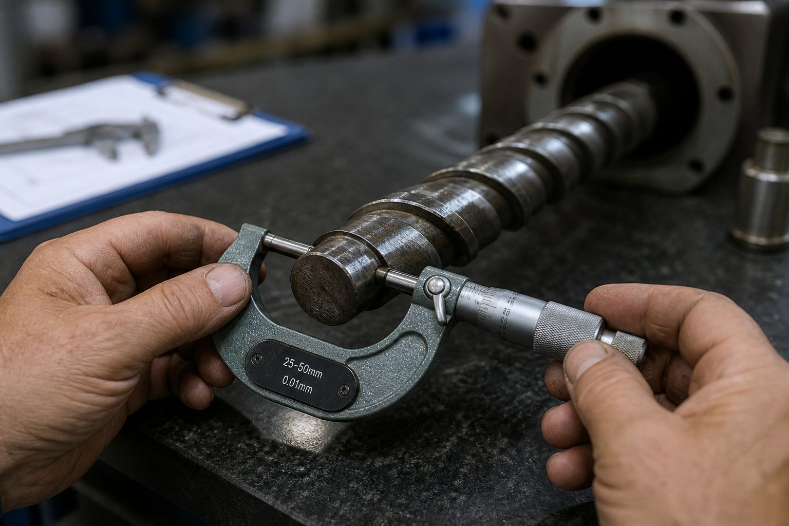
Start by pulling the screw from the barrel and removing all residual resin. Place it on a clean, flat work surface — a granite inspection table is ideal because it provides a true reference plane. Before picking up any measurement instruments, examine the screw visually. Look for obvious damage: pitting, cracks, galling marks on the flight surfaces, and any signs of corrosion from chemically aggressive resins. If a granite table is available, roll the screw slowly and watch for bowing. A bent screw causes metal-to-metal contact inside the barrel, producing adhesive wear patterns that accelerate every other wear mechanism.
With the general condition assessed, move to dimensional measurements using a micrometer. The critical value is the flight-land outer diameter — the dimension that determines clearance between the screw and the barrel wall. Here is a practical tip that improves accuracy: use a parallel test bar spanning two adjacent flights as a bridge, then measure the outer diameter across the bar. This technique eliminates the difficulty of seating micrometer anvils directly on narrow, potentially worn flight lands.
Take readings at multiple positions along the screw's length. Do not measure only the metering zone and assume the rest is fine. As Plastics Technology's detailed analysis of screw wear patterns demonstrates, the majority of flight OD wear concentrates in the transition section and the last few turns of the metering zone, where pressure and temperature reach their highest levels. Glass-filled and mineral-filled resins can also cause significant wear in the feed section, where hard particles compact against the flight surfaces with limited melt lubrication.
Beyond the flights, inspect the non-return valve (check ring assembly) carefully. This is the component that seals the melt pool during the injection stroke, and even modest wear on its sealing surfaces allows melt backflow that directly reduces shot-volume consistency. Check for grooves, scoring, or uneven wear on the ring's seating surfaces. A worn check ring often explains the frustrating shot-to-shot weight variation that many processors initially attribute to material or machine hydraulics.
Do not forget to measure the barrel bore at the same time. A bore gauge inserted from each end of the barrel reveals whether the barrel has worn concentrically or developed localized oval spots. Comparing screw OD to barrel ID gives you the actual radial clearance — the number that truly governs leakage flow and its downstream effects on output and melt quality.
Purging Best Practices to Extend Screw Life
Every resin change, every color transition, and every planned shutdown is an opportunity to either protect your screw or accelerate its deterioration. Proper purging removes degraded material that would otherwise carbonize in dead spots and act as abrasive contamination on subsequent runs. Poor purging — or no purging at all — leaves residue that bakes onto flight surfaces, narrows channel geometry, and creates the localized hot spots that produce black specks in finished parts.
The first decision is whether to use a commercial purging compound (CPC) or simply flush with the next production resin. Running resin through until the barrel appears clean may work for straightforward color changes between similar polymers, but the hidden cost of that approach — extended downtime, wasted resin, and incomplete cleaning — frequently exceeds the cost of a purpose-formulated compound. Commercial purging compounds work through mechanical scrubbing action, chemical cleaning action, or both, and they are specifically designed to dislodge carbonized deposits that production resins cannot remove on their own.
When selecting a purging compound, match it to your situation:
- Mechanical purging compounds — use high-viscosity or abrasive-filled formulations that physically scrub barrel walls and screw surfaces. Best for removing heavy carbon buildup and for transitions between resins with widely different processing temperatures.
- Chemical purging compounds — use foaming or reactive agents that penetrate and loosen degraded material from dead spots and tight clearances. Best for heat-sensitive resins like PVC where aggressive mechanical scrubbing could damage surfaces or generate additional degradation.
- Hybrid formulations — combine both mechanisms for general-purpose cleaning during routine color changes and material transitions.
Temperature management during purging is equally important. Run the purge at the processing temperature of the outgoing resin, not the incoming one, unless the incoming resin requires a higher temperature. Purging at too low a temperature leaves material stuck to surfaces because it has not softened enough to release. Purging at excessively high temperatures risks degrading either the purge compound or the residual resin, creating exactly the kind of carbonized contamination you are trying to eliminate.
For planned shutdowns, purge the barrel thoroughly and then reduce heater temperatures gradually rather than shutting off heat abruptly. Residual resin left in a barrel that cools unevenly can solidify into a hard plug that requires destructive force to remove at restart — a scenario that risks bending the screw, scoring the barrel, or damaging the non-return valve.
When to Rebuild vs. When to Replace
A pulled screw with visible wear presents a clear decision point, but the right answer is not always obvious. Rebuilding costs less and takes less time than buying new, yet not every worn screw is a good rebuild candidate. The injection screw rebuild vs replace decision depends on the severity of wear, the condition of the base material, and whether your processing requirements have changed since the screw was originally specified.
According to Stephen Surley of SpiraMelt Technologies, a well-executed rebuild can restore a screw to like-new condition for a fraction of replacement cost — and quality rebuilds can be performed multiple times on the same screw, sometimes six to eight cycles, far exceeding the three to four rebuilds that many suppliers cite as a general limit. The process involves grinding the screw to a uniform undercut diameter, re-welding the flights with hardfacing alloys like Colmonoy 56, and then final-grinding the OD back to original tolerances.
Use the following framework to guide your decision:
Rebuild when:
- Flight OD wear is within rebuildable tolerance — the base metal has not been reduced beyond the minimum diameter required for a sound hardfacing weld.
- Root wear is moderate and has not created deep pockets or washed-out flight sidewalls that compromise structural integrity.
- The current screw geometry is still correct for your primary resin and application — you are restoring the original design, not compensating for a fundamental mismatch.
- Turnaround time is critical and a replacement screw would require weeks of lead time that production cannot absorb.
Replace when:
- Wear has progressed so far that the screw cannot be reliably rebuilt — severe root wear, flight chipping, or substrate loss makes hardfacing structurally unsound.
- You are upgrading to a different screw design, such as moving from a general-purpose to a barrier configuration, or adding a mixing section.
- Processing requirements have changed — a new resin, a different filler loading, or a modified part design means the original screw geometry is no longer appropriate regardless of its physical condition.
- The screw has already been rebuilt multiple times and dimensional inspections show diminishing returns — flight widths are narrowing with each rebuild cycle, reducing conveying efficiency.
Whichever path you choose, the key to avoiding emergency decisions is documentation. Record flight-land diameters, channel depths, and check-ring dimensions at every scheduled pullout. Plot those values over time against operating hours and resin throughput. This wear-profile data transforms maintenance from reactive firefighting into predictable planning — you will know months in advance when a screw is approaching its wear limit, giving you time to schedule a rebuild during planned downtime or order a replacement before production is at risk.
A robust screw-maintenance program is not built on a single inspection — it is built on a documented history of measurements that reveals the wear trajectory long before quality begins to suffer.
The SPI Dimensional Guidelines provide a useful reference for determining when a component has worn beyond acceptable limits, though these should be treated as starting points. The actual replacement threshold for your operation depends on resin viscosity, quality tolerances, and how much process-window narrowing you can absorb before reject rates become unacceptable.
Diagnosis tells you what is happening. Maintenance extends the interval between replacements. But the most impactful decision — the one that determines how much life a screw delivers and how well it performs across that lifespan — is still the original selection. Pulling together every variable discussed so far into a structured selection and sourcing process is what separates processors who repeatedly fight screw-related problems from those who solve them once and move on.
How to Choose and Source the Right Injection Screw for Your Application
Every topic covered in this article — anatomy, screw types, compression ratio, metallurgy, wear diagnosis — converges on a single practical moment: the point where you specify and order a plasticizing component that will either solve your processing challenge or perpetuate it. Having the knowledge is one thing. Translating it into a confident purchasing decision requires a structured process that accounts for every variable and leaves nothing to assumption.
A Step-by-Step Screw Selection Framework
Rushing straight to a supplier catalog and picking a screw by barrel diameter is how most selection failures begin. Instead, work through the following sequence. Each step builds on the one before it, ensuring that your final specification reflects the full picture of your resin, your machine, and your quality requirements.
- Identify your primary resin and any fillers or additives. This is the foundation of every decision that follows. A neat, unfilled polypropylene and a 30% glass-filled nylon place completely different demands on screw geometry, compression ratio, and metallurgy. Document the resin grade, filler type and loading percentage, any colorant or additive concentrates, and the percentage of regrind in your blend. If you run multiple resins on the same machine, identify the most demanding one — that is the material your screw must be designed to handle.
- Determine shot size relative to barrel capacity. Calculate total shot weight including runners, sprue, and cushion. Convert that weight to volume using the melt density of your specific resin, then verify that barrel utilization falls within the recommended 20-80% range. As Topstar's configuration guide emphasizes, matching shot size to screw diameter ensures the injection stroke stays between one and three times the screw diameter — the zone where metering accuracy and recovery efficiency are both optimized.
- Select the appropriate compression ratio for your polymer family. Use the directional guidelines covered earlier: moderate ratios (2.0:1 to 2.5:1) for amorphous resins, higher ratios (2.5:1 to 4.0:1) for semi-crystalline polymers, and low ratios (1.5:1 to 2.0:1) for heat-sensitive materials like PVC. If you process regrind with low bulk density, consider that feeding and melting demands may need to be addressed independently rather than through a single standard ratio.
- Choose the screw type — GP, barrier, or mixing-enhanced. A general-purpose three-zone screw handles diverse commodity resins with moderate quality requirements. Upgrade to a barrier design when processing semi-crystalline resins at high throughput or when unmelted particles persist despite process optimization. Add dispersive mixing elements (Maddock, fluted) for pigment-critical or glass-filled applications, and distributive elements (pin, pineapple) for color-concentrate blending and regrind homogenization.
- Specify the base material and surface treatment based on your wear profile. Standard nitrided alloy steel handles unfilled commodity resins cost-effectively. Glass-filled or mineral-filled formulations demand tungsten carbide coatings or CPM powder metallurgy construction. Corrosive resins require chrome plating for mild exposure or bimetallic construction for severe chemical attack. Always specify screw and barrel materials as a matched pair to prevent the softer component from wearing disproportionately.
- Verify L/D ratio compatibility with your machine. Most injection molding machines accept screws in the 20:1 to 24:1 L/D range, but confirm the actual flighted length your barrel accommodates. A longer L/D improves melting and mixing for challenging resins; a shorter L/D reduces residence time for thermally sensitive polymers. The right value is the one that matches your resin's thermal stability and melting characteristics — not simply the longest option available.
Following this sequence does not guarantee perfection on the first attempt, but it eliminates the most common and costly selection errors. Each step forces you to make a data-driven decision rather than defaulting to "whatever the last screw was" or "whatever fits the barrel."
Working With a Screw Manufacturer for Custom Solutions
Standard catalog screws solve standard problems. When your application involves unusual filler loadings, tight quality tolerances, heat-sensitive formulations, or a machine that has been repurposed for a different resin family, a custom-engineered screw delivers results that off-the-shelf options cannot match. The key is providing your manufacturer with enough information to design intelligently rather than guess conservatively.
Before contacting any supplier, prepare the following details. The more complete your information package, the more precisely the manufacturer can tailor the screw to your actual needs:
- Machine make and model — this identifies the barrel bore, spline configuration, and any proprietary interface dimensions.
- Barrel bore diameter and overall barrel length — critical for establishing L/D ratio and verifying physical fit.
- Current screw dimensions — if you have a screw to replicate or improve upon, provide flight OD, root diameters in each zone, channel depths, pitch, and overall flighted length. A dimensioned drawing or a copy of the original specification sheet is ideal.
- Primary resins processed — include grade designations, filler types and percentages, and any additives such as flame retardants, UV stabilizers, or foaming agents.
- Specific quality issues to solve — unmelted particles, poor color dispersion, excessive melt temperature, burn marks, short shots, or inconsistent part weight. Describing the problem you need to eliminate gives the manufacturer a clear design target rather than a vague request for "something better."
- Wear history — how long the previous screw lasted, what type of wear was observed (abrasive, corrosive, adhesive), and whether the barrel has also been measured for wear. This data drives material and coating recommendations.
Processors and machine rebuilders looking for custom injection molding screw barrel sourcing should evaluate manufacturers that specialize in application-specific plasticizing components rather than general machine parts. NANHAIYA, for instance, focuses specifically on precision-manufactured injection molding screw and barrel sets, serving factories, rebuilders, and maintenance engineers who need replacement components engineered for particular resin challenges. Their product range covers bimetallic construction, tailored surface treatments, and custom screw geometries designed around the exact processing conditions a customer describes — the kind of consultative approach that produces a screw matched to your application rather than a generic catalog fit.
Regardless of which manufacturer you work with, treat the quoting process as a collaborative engineering conversation. A supplier who asks detailed questions about your resin, your wear patterns, and your quality targets before recommending a specification is far more likely to deliver a component that performs than one who simply asks for barrel diameter and lead time.
The right injection screw is not the most expensive or the most advanced — it is the one precisely matched to your resin, your machine, and your part requirements.
That principle ties together everything this article has covered. Anatomy and geometry give you the vocabulary to describe what you need. Screw types and compression ratios narrow the design space to a handful of viable options. Material and coating selection protects the investment. Wear diagnosis and maintenance extend its productive life. And a disciplined selection framework ensures that the next screw you install is not just a replacement — it is the right tool for the job, specified with the same rigor you would apply to any other critical production decision.
Frequently Asked Questions About Injection Screws
1. What does an injection screw do in an injection molding machine?
An injection screw performs two roles within each molding cycle. During recovery, it rotates inside a heated barrel to convey, compress, and melt polymer pellets into a homogeneous melt pool. During injection, it stops rotating and pushes forward like a plunger, forcing the accumulated melt through the nozzle into the mold cavity under high pressure. This dual function of rotating plasticator and reciprocating plunger makes it the single most influential component governing melt quality, shot-to-shot consistency, and cycle time. Specialized manufacturers such as NANHAIYA offer custom screw and barrel sets at https://www.nhyscrews.com/products/injection-molding-screw-barrel, engineered for specific resin profiles and machine configurations.
2. What is the difference between an injection screw and an extrusion screw?
The fundamental difference lies in how each screw moves. An injection screw reciprocates — it rotates to melt resin, then drives forward axially to inject the shot into a mold. An extrusion screw only rotates continuously in a fixed position, pushing melt through a die for continuous output. This operational distinction leads to several design differences: injection screws require a non-return valve at the tip, use shorter L/D ratios (typically 20:1 to 24:1 versus 24:1 to 36:1 for extrusion), and feature flight geometries optimized for batch metering accuracy rather than maximum continuous throughput. Installing an extrusion screw in an injection machine causes inconsistent shot weights, melt backflow, and potential mechanical damage.
3. How do I choose the right compression ratio for my injection screw?
Compression ratio — the feed-zone channel depth divided by the metering-zone channel depth — must match your polymer family. Amorphous resins like PS and ABS work well with moderate ratios around 2.0:1 to 2.5:1 because they soften gradually. Semi-crystalline polymers such as PE, PP, and nylon need higher ratios of 2.5:1 to 4.0:1 to overcome their sharp melting points and density changes. Heat-sensitive materials like PVC require low ratios of 1.5:1 to 2.0:1 to prevent shear-induced degradation and corrosive gas release. A mismatched ratio causes defects ranging from unmelted particles (too low) to burn marks and material decomposition (too high).
4. What are the signs that an injection screw needs to be replaced or rebuilt?
Key indicators include short shots or incomplete fills despite stable dosing positions, increasing shot-to-shot part weight variation, poor color dispersion, longer recovery times, and burn marks caused by resin stagnation in worn dead spots. To confirm wear, pull the screw and measure flight-land outer diameters at multiple points, focusing on the transition and metering zones where wear concentrates most. A rebuild is appropriate when flight OD loss remains within weldable tolerance and the original geometry still suits your resin. Replace the screw when wear is too severe for reliable hardfacing, when upgrading to a barrier or mixing design, or when processing requirements have changed.
5. What screw material and coating should I use for glass-filled or corrosive resins?
For glass-filled or mineral-filled resins, prioritize abrasion resistance with tungsten carbide coatings (HVOF or PTA applied) on tool-steel substrates for moderate filler loads, or CPM powder metallurgy through-hardened screws for severe applications above 30% glass content. For corrosive resins like PVC or fluoropolymers, hard chrome plating provides budget-friendly protection for mild exposure, while bimetallic construction with nickel-based alloys delivers superior resistance for aggressive chemistries. When both abrasion and corrosion are present, bimetallic screw and barrel sets are nearly mandatory. Suppliers like NANHAIYA (https://www.nhyscrews.com/products/injection-molding-screw-barrel) provide custom bimetallic and coated plasticizing components matched to specific resin challenges.
Written by
Nanhaiya Technical Team
Zhoushan Nanhaiya Plastic Machinery Co., Ltd.
The Nanhaiya technical team supports screw and barrel manufacturing projects through application review, technical communication, custom manufacturing coordination, and production and quality control.
Discuss Your Application
Related Articles
More insights on screw barrel technology and plastics processing.

What Nobody Tells You About Screw Barrel For Plastic Machine Design
Oct 10, 2026
Learn how screw barrel for plastic machine design affects melt quality, throughput, and wear life. Covers geometry, resin matching, troubleshooting, and sourcing.
Read Article
Single Screw Extruder for Sheet: Stop Guessing, Start Specifying
Oct 9, 2026
Learn how to specify a single screw extruder for sheet production. Covers screw geometry, resin-specific processing, troubleshooting, and maintenance best practices.
Read Article
PE Pipe Extruder Machine: What Datasheets Won't Tell You
Oct 9, 2026
Learn how a PE pipe extruder machine works, key specs explained, material grade selection, maintenance tips, and buyer guidance beyond the datasheet.
Read ArticleLooking for something else?
Search by material, symptom or product and jump straight to the relevant page.
These are navigation suggestions based on keyword matching — not a quotation, not a delivery commitment, and not a substitute for engineering review. Final specification is confirmed by our engineers against your drawings and processed material.
Need help with screw barrel selection?
Share your machine model, processed material and application. Our team can help with pricing and technical support.