

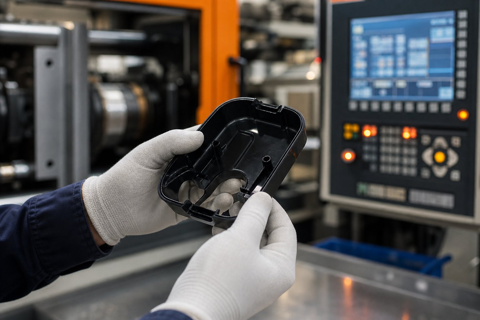
Why Systematic Troubleshooting Outperforms Random Parameter Changes
Imagine this: a part comes off the press with silver streaks radiating from the gate. The operator bumps melt temperature up ten degrees. The streaks persist. Someone else drops injection speed. Still there. A third person increases back pressure. Two hours, fifty pounds of scrap, and a missed delivery window later, the team discovers the dryer hopper ran empty overnight. The fix was never on the machine controller — it was in the material handling system.
This scenario plays out on production floors every day. Random parameter adjustments rarely solve injection molding defects because each defect has a specific root cause that demands a specific remedy. As industry experts have pointed out, increasing pack pressure will never fix burn marks, and raising mold temperature will never cure moisture-induced splay. Yet the instinct to start turning dials remains the default response for many processors — and it costs real money in wasted resin, lost machine hours, and delayed shipments.
The good news? Injection molding troubleshooting is not an innate talent reserved for thirty-year veterans. It is a teachable diagnostic skill built on pattern recognition, structured reasoning, and disciplined testing. This guide teaches you the thinking process behind defect resolution, not just a list of moulding defects and their quick fixes.
Reactive Fixes vs. Systematic Diagnosis
The difference between a reactive fix and a systematic diagnosis comes down to one question: did you identify the defect before you touched a parameter? Reactive troubleshooting skips observation entirely and jumps straight to adjustment. Systematic diagnosis follows a deliberate sequence — examine the part, classify the problem, form a hypothesis, test one variable, and verify the result holds. That sequence is faster, not slower, because it eliminates the cascading side effects that random changes introduce. A processor who documents the defect location, pattern, and frequency across cavities narrows the investigation to a handful of variables before ever opening the controller screen.
First-Article vs. Production-Run Troubleshooting
Not all troubleshooting situations are equal. When you are starting up a new mold or dialing in a first article, you expect problems. Water lines may be connected incorrectly, gate sizes may need adjustment, and the process window is still unknown. The mindset here is exploratory — you are building a validated baseline from scratch through methodical short-shot studies, gate seal experiments, and cooling evaluations.
Production-run troubleshooting is fundamentally different. A validated process that has been running stable for days or weeks does not suddenly fail without a reason. Something changed — a new resin lot, a worn check ring, a shifted mold component, or an operator deviation. Here, the mindset is investigative: verify every setup condition against the documented process sheet before adjusting a single parameter. As experienced processors emphasize, the first step is always to determine what changed, not to start compensating for common injection molding defects you haven't yet confirmed.
How to Navigate This Guide
This article is designed with two entry points. If you already know the defect name — splay, flash, warpage, short shots — jump directly to the relevant section for cause analysis and parameter adjustment guidance. If you see a symptom on the part but cannot name the specific molding defects you are dealing with, start with the diagnostic framework in the next section. It will walk you through observation, categorization, and hypothesis generation so you can pinpoint the problem before searching for the fix.
Roughly 80% of injection molding problems trace back to only four root-cause categories: Machine, Mold, Material, and Method. Master these four domains, and you can systematically diagnose nearly any defect you encounter.
Every section that follows builds on this principle — organizing causes, adjustments, and verification steps around these four categories so you develop a repeatable skill, not just a one-time answer. The real question, then, is not what went wrong with the part, but where in the system the failure originated — and that question demands a structured method to answer.
A Five-Step Diagnostic Framework for Every Molding Defect
Knowing that four root-cause categories drive most defects is powerful — but only if you have a reliable method for working through them. A troubleshooting guide for injection molding is only as useful as the thinking process behind it. Without a consistent sequence, even experienced processors fall back into the habit of adjusting whatever parameter is closest to their fingertips.
The framework below transforms defect resolution from guesswork into a repeatable diagnostic skill. Each step feeds the next, and skipping any one of them dramatically increases the chance of chasing the wrong variable.
- Observe — Examine the part in detail: texture, color, location, and pattern of the defect.
- Categorize — Classify the defect as cosmetic or structural, and assign it to a molding cycle phase.
- Hypothesize — Use the 4M framework (Machine, Mold, Material, Method) to generate likely root causes.
- Test — Adjust one parameter at a time, in the correct direction, while monitoring for secondary effects.
- Verify — Confirm the fix holds across multiple shots and document the corrective action.
Steps 1 and 2 — Observe the Part and Categorize the Defect
Pick up the part. Don't glance at it — study it. Where exactly does the defect appear? Is it near the gate, at the end of fill, along a weld line, or on the ejector side? Does the surface feel rough, glossy, raised, or depressed? You'll notice that defect location alone eliminates entire categories of causes. Silver streaks radiating from the gate suggest a material or shear issue, while burn marks at the last-to-fill area point toward trapped gas and inadequate venting.
Next, determine frequency. Does the defect show up on every shot or intermittently? Does it appear in all cavities or only specific ones? A defect isolated to one cavity almost always signals a mold issue — a plugged vent, a restricted gate, or a cooling imbalance — rather than a machine or material problem. Intermittent defects, on the other hand, often point to shot-to-shot variation from check ring inconsistency or material feed problems.
Categorization sharpens the investigation further. Ask two questions: Is this defect cosmetic or structural? And which phase of the molding cycle produced it? A sink mark is a pack-phase defect. Jetting is a fill-phase defect. Warpage is a cooling-phase defect. Drag marks are ejection-phase defects. Assigning defects in injection molding and their troubleshooting steps to the correct phase immediately narrows which parameters matter and which ones you can ignore entirely.
Step 3 — Generate Hypotheses Using Root Cause Categories
Here is where the 4M framework earns its value. Instead of guessing, you systematically walk through each category and ask: could something in this domain explain what I'm seeing?
- Machine: Has the barrel temperature profile shifted? Is the check ring sealing consistently? Are injection speed and pressure performing linearly? Tests like the dynamic check ring test and injection speed linearity test can reveal hidden machine-side inconsistencies that don't trigger alarms but absolutely affect part quality.
- Mold: Are vents clean and open? Is coolant flowing through every circuit at the correct rate? Has any component shifted or worn since the last run?
- Material: Was the resin dried to specification? Has the lot number changed? What is the current regrind ratio?
- Method: Does the current setup match the documented process sheet? Has cycle time drifted? Did a different operator set up the job?
The goal is not to investigate every possibility — it's to generate a ranked short list of likely causes based on what you observed in Steps 1 and 2. A seasoned troubleshooter using this approach can typically narrow the field to two or three hypotheses within minutes. As the 4M methodology developed by Kerkstra and Brammer emphasizes, always ask what changed before assuming a process parameter needs correction. An injection molding troubleshooting chart organized by these four categories can serve as a quick visual reference to make sure no domain gets overlooked during this step.
Steps 4 and 5 — Test Adjustments and Verify Stability
This is where discipline separates effective troubleshooting injection molding problems from aimless tinkering. The rule is simple and non-negotiable: change one parameter at a time. Adjusting injection speed and melt temperature simultaneously makes it impossible to know which change produced the result — or which one introduced a new side effect.
Choose the parameter most directly linked to your top hypothesis and adjust it in a deliberate direction. If you suspect insufficient packing is causing sink marks, increase pack pressure by a defined increment — not a random bump. Then collect several shots, inspect them, and compare. Did the sink marks reduce? Did flash appear at the parting line? Every adjustment carries the potential for a secondary defect, so monitor the part holistically, not just in the area where the original problem appeared.
Which parameter should you adjust first? Prioritize the variable with the most direct causal link to the defect phase. For fill-phase defects, start with injection speed or melt temperature. For pack-phase defects, start with packing pressure or hold time. For cooling-phase defects, evaluate coolant temperature and cooling time before touching anything on the injection side. This sequence-based approach prevents the common trap of adjusting a fill parameter to solve what is fundamentally a cooling problem.
Verification is the step most often skipped — and it's the reason "fixed" defects return the next morning. Once the defect disappears, run a statistically meaningful number of shots to confirm stability. Five or ten parts may look clean, but thirty to fifty consecutive shots provide far greater confidence. Document the corrective action: which parameter changed, by how much, and what the final setpoint is. Update the process sheet so the next operator inherits a validated baseline, not a mystery.
This five-step sequence works regardless of the defect type, the resin, or the machine platform. It is the foundation for every troubleshooting for injection molding process scenario covered in the sections ahead — each of which applies these same principles to specific defect families, cycle phases, and material behaviors. The difference between a processor who solves problems in minutes and one who burns hours is rarely experience alone; it's whether they follow a method or follow a hunch.
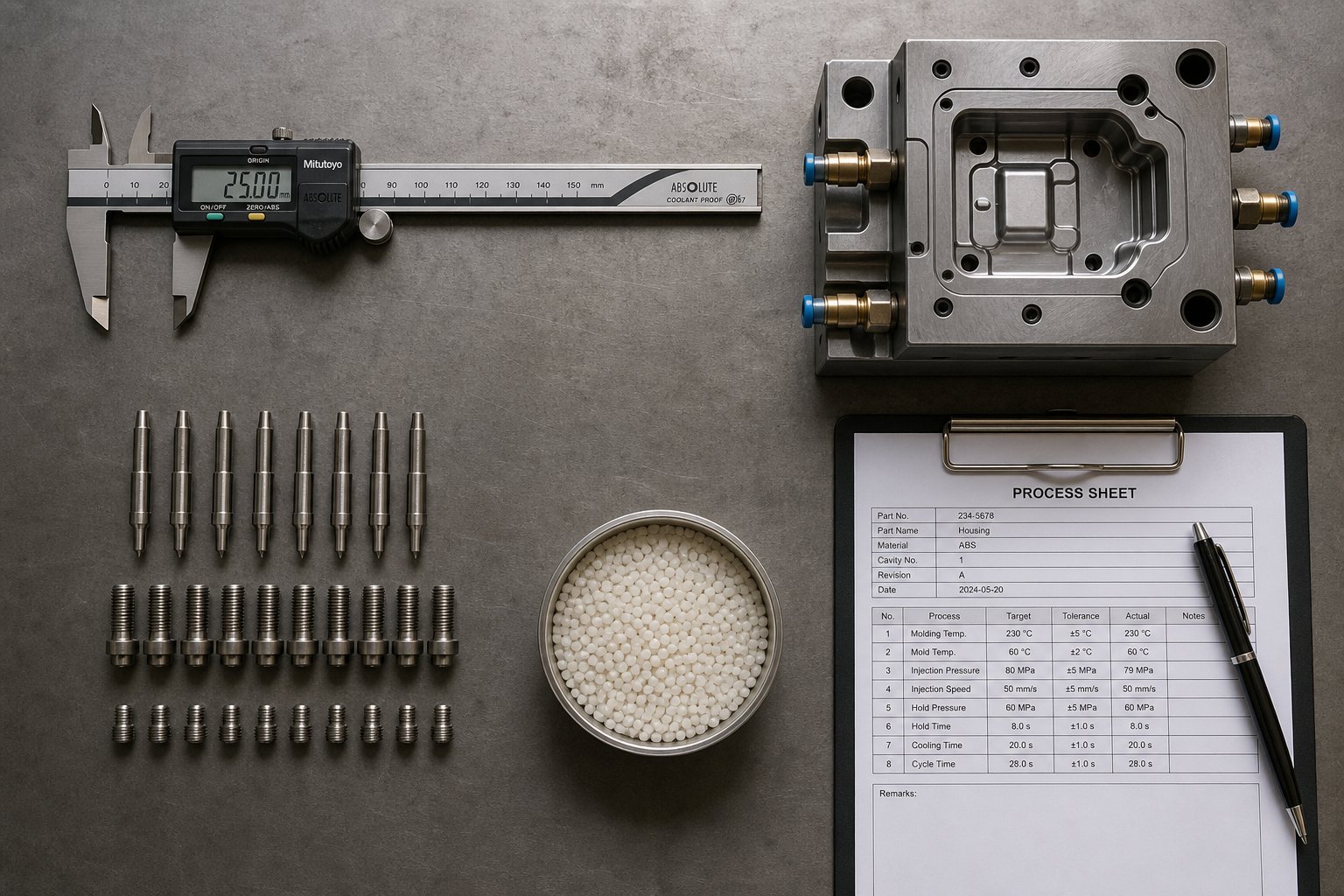
Classifying Root Causes With the 4M Diagnostic Method
Generating a hypothesis is only useful if you have a structured map of where problems actually originate. The five-step framework tells you how to think — the 4M root-cause system tells you where to look. Every injection molding defect, from a subtle flow line to a catastrophic short shot, traces back to one or more of four domains: Machine, Mold, Material, and Method (operator and process). Sorting causes into these categories before touching a single setting prevents the most expensive mistake in injection molding troubleshooting — investigating the wrong domain entirely.
The table below serves as a quick-reference root-cause matrix. When a defect appears, scan the "Typical Defects Produced" column to find your symptom, then follow the row back to the diagnostic check that confirms or eliminates that category.
| Category | Common Causes | Diagnostic Check | Typical Defects Produced |
|---|---|---|---|
| Machine | Barrel temperature drift, worn screw flights, check ring leakage, inconsistent injection speed, heater band failure, low plasticizing capacity | Run check ring repeatability test (shot weight variation over 20 shots); verify injection speed linearity; compare actual vs. set barrel temperatures | Short shots, shot-to-shot weight variation, splay, color mixing problems, burn marks from degraded resin, inconsistent dimensions |
| Mold/Tooling | Blocked or shallow vents, undersized gates, cooling circuit imbalance, worn parting line surfaces, damaged cavity finish, shifted slides or cores | Inspect vents for carbon buildup; run mold with pressure-sensitive paper at parting line; measure coolant flow rate and delta-T per circuit | Burn marks at end-of-fill, flash at parting line, warpage, cavity-to-cavity variation, surface blemishes, drag marks |
| Material | Excess moisture content, contamination from regrind or foreign resin, lot-to-lot MFI variation, exceeded regrind ratio, additive incompatibility | Verify dryer dewpoint and residence time; test moisture content with analyzer; run FTIR on suspect streaks; confirm lot certificate against spec | Moisture splay, contamination splay, brittleness, delamination, color shifts, voids from volatiles |
| Method (Operator/Process) | Cycle time inconsistency (manual mode), parameter drift from undocumented changes, incorrect material handling, wrong process sheet revision | Compare current setpoints to documented baseline; review cycle time log for variation; audit material loading and drying procedure | Dimensional drift, intermittent short shots, random cosmetic defects, process instability across shifts |
Machine and Plasticizing Unit Causes
Machine-side issues are deceptive because they develop gradually. A barrel heater band doesn't fail all at once — it drifts. A check ring doesn't stop sealing overnight — it leaks a little more with each thousand shots. That slow degradation means processors often compensate unconsciously, nudging pressure up or speed down over weeks until the process is running on a patchwork of adjustments that mask the real problem.
The plasticizing unit — screw, barrel, and check ring — deserves special attention because it is the heart of shot consistency. A worn screw with reduced flight depth produces poor melt homogeneity, which shows up as uneven color distribution and injection molding color mixing problems that no amount of back-pressure adjustment will resolve. Worn barrel walls allow melt to hang up in dead spots, creating degraded material that streaks through otherwise clean parts. A leaking check ring bleeds pressure during the pack-and-hold phase, producing shot-to-shot weight variation that mimics a dozen other defects. Industry analysis confirms that many persistent molding defects stem from mechanical wear rather than processing parameters, and that regular inspection of these components is essential to maintaining quality.
How do you confirm plasticizing wear? Run a simple check ring repeatability test: set the machine to a fixed shot size and weigh twenty consecutive shots. If weight variation exceeds 0.5% of nominal, the check ring is suspect. Measure screw and barrel clearance with a bore gauge — most manufacturers specify maximum allowable clearance, typically around 0.004 to 0.006 inches depending on barrel diameter. When measurements confirm wear beyond tolerance, the fix is component replacement, not further process compensation. For factories that need precision-engineered replacement plasticizing components or custom screw barrel configurations to restore shot consistency, NANHAIYA's injection molding screw barrel solutions provide a practical sourcing option with configurations designed for specific resin families and application demands.
Mold and Tooling Causes
Mold-related root causes share a distinguishing fingerprint: they produce defects that remain fixed in location regardless of process changes. If a burn mark sits in the same spot on every shot no matter how much you slow injection, that's a venting problem, not a speed problem. If one cavity consistently runs short while the others fill cleanly, that's a gate restriction or a cooling imbalance in the tool, not insufficient machine pressure.
Venting is the single most overlooked mold maintenance item. Carbon buildup from outgassing gradually seals off vent channels, reducing their effective depth from the specified 0.0005–0.003 inches down to near zero. The result is trapped gas that causes burn marks, short shots in last-to-fill areas, and elevated cavity pressure that triggers flash elsewhere in the tool. Cleaning vents on a scheduled cycle — not just when defects appear — prevents a large percentage of mold-related rejects.
Gate sizing and cooling circuit balance also fall into this category. An undersized gate restricts flow and creates excessive shear heating at the gate area. Cooling circuits with blocked or partially restricted waterlines produce temperature differentials across the mold that drive warpage and dimensional variation. The diagnostic approach for any suspected tooling problem is straightforward: inspect the mold physically. Pressure-sensitive paper at the parting line reveals clamp force distribution issues. Coolant flow meters and temperature sensors on each circuit expose imbalances that are invisible from the machine controller. Injection mold repair — whether addressing parting line damage, worn slides, or eroded gate inserts — is sometimes the only path to a permanent fix. A process adjustment that compensates for a tooling deficiency is temporary at best and creates a fragile, narrow operating window.
Material and Process Operator Causes
Material-related causes are responsible for some of the most frustrating defects because they can appear and disappear without any process change. A new resin lot arrives within specification but at the high end of its melt flow index range, and suddenly parts that ran perfectly for weeks begin showing flash or dimensional shifts. Contamination injection molding problems — from incompatible regrind, foreign resin left in the hopper, or purge compound residue in the barrel — produce random splay, delamination, or color contamination that mimics several other defect types.
Moisture is the material variable that trips up the most processors. Hygroscopic resins like nylon, polycarbonate, and PBT absorb water from the atmosphere, and even a small excess — 0.02% above specification for PC, for instance — produces moisture splay that looks nearly identical to shear splay or thermal degradation splay. The diagnostic step is simple but essential: verify dryer dewpoint and material residence time in the hopper before adjusting anything on the press. If the material isn't dry, no process change will eliminate the streaks.
Operator and method causes round out the 4M system. These are the human-side variables: an operator running in semi-automatic mode with inconsistent cycle times, an undocumented parameter change made on the previous shift, or a setup that doesn't match the current revision of the process sheet. The diagnostic check is equally straightforward — compare every current setpoint against the validated baseline. Cycle time logs, if available, reveal whether gate-open-to-gate-close consistency has drifted. Plastic injection mold repair and process optimization deliver lasting results only when the documented baseline is maintained by every operator on every shift. Without that discipline, the same problems cycle through the plant on a predictable loop.
These four domains don't operate in isolation. A worn check ring (Machine) combined with a high-MFI resin lot (Material) can push a stable process past its tolerance window in ways that neither factor alone would trigger. The real power of the 4M method lies in its ability to isolate which domain changed — and knowing that distinction is what separates a targeted correction from yet another round of blind adjustments. With the root-cause map in hand, the next challenge is learning to read the defect itself: what does each surface flaw actually look like, and how do you tell similar-looking symptoms apart?
Identifying and Resolving Surface and Cosmetic Defects
Knowing which root-cause domain to investigate means little if you misidentify the defect sitting in your hand. Two defects can look deceptively similar — silver streaks from moisture and silver streaks from shear, for instance — yet demand completely opposite corrective actions. Accurate visual identification is the first real test of systematic diagnosis, and it's where many processors stumble. The defects below represent the most frequent surface-quality failures you'll encounter, organized by the visual details that distinguish one from another.
Splay Sub-Types and How to Tell Them Apart
Splay in injection molding appears as silver or white streaks radiating outward along the flow path. But not all splay is created equal, and treating every occurrence the same way leads to wasted hours. There are four distinct sub-types, each with a telltale visual signature.
- Moisture splay produces streaks that appear randomly across the part and shift location from shot to shot. The purge puddle often looks foamy or riddled with bubbles. As industry experts note, the inconsistency of streak placement is the strongest indicator — if the pattern never repeats in the same spot, suspect moisture first.
- Shear splay is the opposite: it recurs in the same location on every shot. Streaks near the gate suggest excessive entry speed or a gate obstruction, while mid-flow streaks point to a flow-path restriction or burr inside the mold. End-of-fill shear splay indicates material "waxing" — becoming more viscous as it cools — and overheating at the last-to-fill region.
- Heat splay resembles moisture splay visually but comes with additional clues: a burnt or chemical smell, material stickiness, and discoloration ranging from yellow to brown. The streaks may cover the entire part when barrel temperatures or residence time exceed the resin's thermal stability window.
- Additive splay occurs when colorants, flame retardants, or other additives outgas or decompose during processing. The streaks often carry a distinct color tint that differs from the base resin, making them easier to isolate once you know to look for that contrast.
The critical diagnostic step for injection molding splay is simple: check whether the streak pattern is random or fixed. Random placement investigates toward moisture or heat. Fixed placement investigates toward shear or mold-side obstructions. That single observation eliminates half the possible causes before you open the controller.
Burn Marks — Gas Burns vs. Shear Burns
Injection molding burn marks show up as dark discolorations ranging from rust-brown to charred black, but the two primary sub-types appear in very different locations and demand different fixes.
Gas burns — sometimes called a gas mark in injection moulding — result from trapped air compressing and igniting inside the cavity (a phenomenon known as dieseling). They almost always appear at the last-to-fill areas: far corners, the ends of ribs, or blind bosses where air has no escape path. The discoloration is typically dark brown to black and localized to a small, repeatable area. The smell is sharp and acrid. The root cause is nearly always inadequate venting — either the vents were undersized to begin with, or carbon deposits from previous runs have sealed them shut.
Shear burns look different. They tend to appear near gates or along thin-wall transitions where material velocity spikes. The color leans more toward amber or yellow-brown rather than the deep charring of gas burns. Shear burns signal that injection speed is too high for the local geometry, or that a flow restriction is generating excessive frictional heating. Reducing fill speed in the affected profile stage is the first corrective step — but watch for short shots if you slow down too aggressively.
Flow Marks, Sink Marks, and Gate Blush Identification
Flow marks appear as wavy, off-color lines or concentric rings on the part surface, usually near the gate or along long flow paths. They form when the melt front hesitates or cools unevenly against the cavity wall. A related but visually distinct defect is jetting — a snake-like, rope-shaped pattern that occurs when melt squirts through the gate without contacting the cavity wall, then folds over itself as the cavity fills. Jetting patterns are unmistakable once you've seen one: they look like a worm trail frozen in plastic. The fix starts with slowing the initial injection speed to allow the melt front to establish contact with the cavity surface.
Injection molding sink marks present as shallow depressions on the outer surface, typically located directly opposite thick features like ribs, bosses, or wall-thickness transitions. They form when interior material shrinks during cooling and pulls the still-pliable skin inward. Distinguishing a sink mark from an internal void is straightforward: sinks are visible on the surface without cutting the part, while voids hide inside the wall and require cross-sectioning to confirm. Part design plays a direct role — inconsistent wall thickness and improperly sized ribs are the primary design-side contributors.
Gate blush is the cloudy, whitened discoloration that appears immediately around the gate area. It results from shear heating as material passes through the gate restriction at high velocity. In some cases, gate blush indicates structural weakness at the gate location, not merely a cosmetic flaw. Adjusting gate diameter, reducing initial injection speed, or increasing mold temperature at the gate region typically resolves the condition. A related concern is gate vestige injection molding — the small nub or mark left when the gate is trimmed or sheared from the part. While not a process defect per se, excessive vestige height or rough shear surfaces often signal that gate geometry or cutoff timing needs refinement.
The quick-reference chart below consolidates the first corrective move for each defect, along with the secondary issue to monitor after making the adjustment.
| Defect | Visual Description | Primary Cause | First Adjustment | Watch For |
|---|---|---|---|---|
| Moisture Splay | Random silver streaks; foamy purge puddle | Excess moisture in resin | Verify dryer operation and material residence time; re-dry resin | Over-drying degradation in sensitive resins (e.g., POM) |
| Shear Splay | Fixed-location silver streaks repeating each shot | Excessive melt velocity or flow obstruction | Reduce injection speed in the affected fill-profile stage | Short shots or flow hesitation marks |
| Heat Splay | Widespread streaks with discoloration or burnt smell | Barrel overheating or excessive residence time | Lower barrel rear-zone temperature; reduce back pressure | Incomplete melt homogeneity or cold slugs |
| Gas Burn | Black/brown char at last-to-fill areas | Trapped air with inadequate venting | Clean or deepen mold vents; reduce final-stage injection speed | Flash at parting line if vents are overcut |
| Shear Burn | Amber/yellow-brown marks near gate or thin sections | Excessive local shear from high velocity | Lower injection speed through the affected zone | Short shots or increased fill time |
| Flow Marks | Wavy rings or lines on surface near gate or along flow path | Melt-front hesitation or low mold temperature | Increase mold temperature; adjust injection speed profile | Longer cycle time from elevated mold temperature |
| Sink Marks | Surface depressions opposite ribs or thick sections | Insufficient packing or excessive wall thickness | Increase pack pressure and hold time; confirm gate seal | Flash at parting line from overpacking |
| Gate Blush | Cloudy whitened area immediately around gate | Shear heating at gate restriction | Reduce initial injection speed; increase mold temperature near gate | Flow marks or jetting from overly slow entry speed |
Surface defects tell you a story — but only if you read the right details. Streak location, color, pattern consistency, and smell each narrow the diagnosis before a single parameter changes. Yet cosmetic flaws are only half the picture. Some defects don't damage the surface at all — they compromise the part's structural integrity, dimensional accuracy, or ability to eject cleanly from the mold. Those failures demand a different set of questions and a different troubleshooting priority.
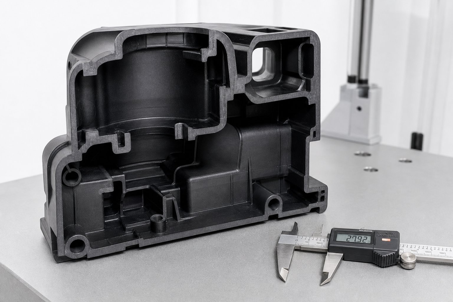
Solving Structural and Dimensional Defects That Compromise Part Function
A sink mark on the backside of a cosmetic cover might be perfectly acceptable. A weld line running through a load-bearing screw boss? That part could crack in the field, trigger a product recall, and cost exponentially more than the fraction of a cent it took to mold. Structural and dimensional defects in injection molding don't always announce themselves visually — some hide inside the wall, some distort the part after ejection, and some reveal their damage only under mechanical load. The troubleshooting priority shifts dramatically when the defect compromises function rather than appearance, because the tolerance for "close enough" drops to zero.
Understanding injection molding defects and causes at the structural level also means understanding how part design features — wall thickness transitions, rib-to-wall ratios, draft angles, and gate locations — directly create or amplify these failures. Many structural defects cannot be fully resolved by process adjustment alone; they require design or tooling changes.
Short Shots and Flash as Opposing Defects
Short shots and flash sit at opposite ends of the same spectrum: one means too little material entered the cavity, and the other means too much. This relationship is critical because the fix for one can directly cause the other if applied carelessly.
A short shot produces an incomplete part — missing features, thin sections that didn't fully form, or entire regions of the cavity left empty. The causes break into three broad categories:
- Insufficient pressure or speed: The machine cannot push enough melt through the flow path before the material freezes off. Increase injection speed first, then injection pressure if speed alone doesn't resolve the fill.
- Restricted flow path: An undersized gate, a cold slug blocking the runner, or a wall section too thin to sustain flow. Inspect the gate and runner system for obstructions. If the geometry is inherently restrictive, raising melt temperature can improve flowability — but monitor for degradation or splay.
- Inadequate venting: Trapped air creates back-pressure that resists the advancing melt front. Clean or deepen vents at the last-to-fill locations. If the short shot disappears when the clamp force is reduced slightly, poor venting is almost certainly the root cause.
Flash — excess material escaping the cavity at the parting line, around ejector pins, or along slide shutoffs — creates more than cosmetic rejects. It drives hidden labor costs from trimming operations, accelerates parting line wear, and in severe cases causes mold damage when the tool closes on solidified flash the next cycle. The parameter adjustments for flash run directly counter to those for short shots:
- Reduce pack pressure to eliminate overpacking — the most common process cause of flash.
- Verify clamp tonnage is adequate for the projected area of the part and runner system. A mold mismatch — running a tool on a machine with insufficient clamp force — produces flash that no process adjustment can eliminate.
- Inspect the parting line for wear, damage, or foreign material. Even a few thousandths of an inch of parting-line recession creates a gap that melt exploits under packing pressure.
The balancing act between these two defects is why process window analysis matters. If eliminating a short shot by increasing pressure immediately triggers flash, the root cause is rarely the process — it's usually a venting limitation, a clamp force shortfall, or parting-line wear that has narrowed the operating window to an impossibly thin band.
Warpage, Voids, and Internal Stress Defects
Warpage is the defect that reveals itself after the part leaves the mold. A component ejects looking perfectly flat, then twists or bows over the next several minutes — or days — as residual stresses relax. The core driver is differential shrinkage: one side or region of the part cools faster, crystallizes differently, or receives more packing pressure than another, creating internal forces that pull the geometry out of specification.
- First, check cooling circuit balance. Measure coolant temperature in and out of each circuit. A delta-T exceeding 3-4 degrees Fahrenheit between opposite sides of the cavity creates the asymmetric cooling that warps parts.
- Evaluate packing uniformity. In multi-cavity tools, cavities farther from the sprue often receive less packing, leading to cavity-to-cavity dimensional variation and warpage patterns that differ by cavity position.
- Assess molecular orientation. Long, thin flow paths align polymer chains in the flow direction, creating anisotropic shrinkage — the part shrinks more across the flow than along it. Increasing mold temperature slows solidification and allows some molecular relaxation, which can reduce orientation-driven warpage.
Voids are warpage's invisible cousin. They form inside thick sections when the outer skin freezes before the interior has fully solidified, and the shrinking core pulls away from itself, leaving a vacuum bubble. But not every void comes from insufficient packing — gas voids result from moisture in the resin or thermal degradation producing volatiles. How do you tell them apart? Cut the part open. Vacuum voids have smooth, shiny interior walls because the plastic simply pulled apart. Gas voids show rough, matte, or discolored inner surfaces from the gas that occupied the space. This distinction matters because the fix for vacuum voids is more packing pressure and longer hold time, while the fix for gas voids is drying the material or reducing barrel temperatures — exactly the wrong direction for the other sub-type.
Weld Lines, Drag Marks, and Ejection Problems
Weld lines form wherever two or more melt fronts converge inside the cavity. What many processors don't realize is that not all weld lines carry the same structural risk. The critical distinction, as RJG explains, lies in the angle at which the flow fronts meet.
A meld line forms when two flow fronts merge and continue flowing in the same direction — imagine two lanes of highway traffic converging into one. Because the material keeps moving after meeting, there's an opportunity to pressurize and partially re-entangle the polymer chains. The resulting joint is weaker than uninterrupted flow but retains meaningful strength.
A knit line is fundamentally different. Here, two flow fronts collide head-on with no remaining cavity to flow through — like a head-on collision at a four-way stop. The polymer chains cannot intermingle effectively, and the joint retains far less strength. Materials with physical fillers like glass fiber are especially vulnerable because the filler particles cannot bridge the interface, further weakening the bond. A knit line in a screw boss, for example, can cause the boss to crack when a fastener is driven into it.
Troubleshooting weld and knit lines involves a combination of process and tooling strategies:
- Increase melt temperature to keep the flow fronts hotter at the point of convergence, improving molecular entanglement.
- Increase mold temperature to slow skin formation and give the fronts more time to bond.
- Raise injection speed so the fronts meet before they cool significantly — but watch for burn marks from trapped air at the convergence point.
- Evaluate gate location changes via flow simulation to move the weld line away from structurally critical areas when process adjustments alone aren't sufficient.
Ejection-phase defects round out the structural category. Injection molding drag marks appear as scuff lines, scratches, or whitened streaks on the part surface in the direction of ejection. They signal that the part is gripping a core, slide, or cavity wall too tightly as it's pushed out. Common causes include insufficient draft angle, rough or damaged mold surfaces, and inadequate cooling time that leaves the part too soft to withstand ejection forces.
Parts sticking injection molding is a related but more severe condition — the part doesn't just drag, it refuses to release entirely. Sticking on the stationary side often indicates too much detail or grip on the cover half relative to the core side. Sticking to ejector pins or lifters typically points to galling, burrs, or polishing done against the grain of ejection. The troubleshooting sequence for ejection problems follows a clear priority:
- Extend cooling time to allow the part to shrink onto the core side more fully before mold opening.
- Slow mold-break speed — aggressive opening velocity can rip parts free unevenly, causing deformation or leaving pieces behind.
- Inspect and polish mold surfaces in the direction of part removal. Polishing against the ejection direction can worsen the problem by creating micro-undercuts.
- Verify draft angles meet the minimum for the resin and texture depth. Textured surfaces require significantly more draft than polished ones — a common oversight during mold design.
Structural defects expose a fundamental truth about injection molding: the process, the tooling, and the part design are inseparable. A rib-to-wall ratio above 60% virtually guarantees sink marks or voids on the opposite surface. A boss without adequate draft will stick regardless of how much mold release you spray. Thin-to-thick wall transitions create hesitation marks during fill and differential shrinkage during cooling. Recognizing these design-driven constraints is what separates a troubleshooter who solves problems permanently from one who patches them temporarily with fragile parameter windows.
Individual defects rarely appear in isolation, though. In practice, a single part often presents two or three problems simultaneously — and fixing one can make another worse. That tension between conflicting parameters is the next challenge worth understanding.
Troubleshooting Defects by Molding Cycle Phase
Before tackling those conflicting parameter scenarios, there's a different diagnostic lens worth mastering — one that organizes defects not by what they look like, but by when they form. Every injection molding cycle moves through four distinct phases: fill, pack and hold, cooling, and ejection. Each phase involves different physical forces, different dominant parameters, and different failure modes. If you can pinpoint which phase produced the defect, you've already eliminated three-quarters of the possible adjustments.
This approach is especially valuable when you see a symptom but can't name the specific defect. You might not know whether those injection molding bubbles are vacuum voids or gas voids — but you probably know they're forming after the cavity fills, during the packing stage. That phase-based starting point immediately focuses your investigation on pack pressure, hold time, and gate seal rather than injection speed or melt temperature.
The table below maps each cycle phase to its associated defects, the key parameters that govern it, and the correct adjustment direction for common injection molding defects and solutions.
| Cycle Phase | Associated Defects | Key Parameters | Adjustment Direction |
|---|---|---|---|
| Fill | Short shots, jetting, flow lines, splay, gas burn marks | Injection speed profile, melt temperature, gate geometry, venting | Increase speed for short shots; decrease speed for jetting and burns; raise melt temp for flow lines; clean vents for gas burns |
| Pack & Hold | Sink marks, voids, flash, dimensional variation | Pack pressure, hold time, gate seal timing, cushion | Increase pack pressure for sinks/voids; decrease pack pressure for flash; extend hold time until gate freeze |
| Cooling | Warpage, residual stress, long cycle times, crystallization defects | Cooling time, coolant temperature, circuit balance, mold temperature | Balance coolant delta-T across circuits; increase cooling time for warpage; optimize mold temp for crystallization control |
| Ejection | Drag marks, parts sticking, ejector pin marks, stress whitening | Draft angles, mold surface condition, ejection speed, cooling time | Increase draft; polish surfaces in ejection direction; slow ejection speed; extend cooling if part is too soft |
Fill Phase — Speed, Temperature, and Flow Path Issues
Fill-phase defects share a common thread: they all relate to how molten plastic enters and travels through the cavity. Jetting injection molding problems, for example, occur when melt squirts through the gate too fast and folds over itself rather than flowing smoothly against the cavity wall. The fix? Slow the initial injection speed so the melt front fans outward from the gate instead of jetting across the cavity.
Injection moulding flow lines — those wavy, off-color rings on the surface — signal that the melt front hesitated or cooled prematurely against the mold wall. Raising mold temperature keeps the surface molten longer and reduces hesitation marks. A burn mark in injection moulding that shows up at the end of fill almost always indicates trapped gas compressing ahead of the advancing flow front. Cleaning vents or reducing final-stage injection speed resolves gas burns without introducing new problems — as long as you don't slow the fill so much that you create a short shot.
The key principle for fill-phase troubleshooting: injection speed profile and melt temperature are your primary levers. Gate geometry and venting are your tooling-side levers. Adjusting pack pressure or cooling time to fix a fill-phase defect is a common mistake that rarely works and often creates secondary issues.
Pack and Hold Phase — Pressure, Time, and Gate Seal Issues
The moment the cavity reaches volumetric fill, the process transitions from velocity control to pressure control. This is where sink marks in injection moulding, voids, flash, and dimensional instability originate. The physics are straightforward: as molten plastic cools, it shrinks. Packing pressure forces additional material into the cavity to compensate for that volumetric contraction. If gate seal occurs too early — meaning the gate freezes before enough material has been packed in — thick sections starve for material and either sink inward or form internal voids.
Hold time is only effective as long as the gate remains open. Extending hold time beyond gate freeze does nothing productive — it just wastes cycle time. A gate seal study, where you plot part weight against hold time, reveals the exact point where additional hold time stops adding material. That inflection point defines your minimum effective hold time.
Flash during the pack phase indicates that cavity pressure has exceeded the mold's sealing capability. Before reducing pack pressure, verify that the clamp tonnage is appropriate and that the parting line isn't worn. Reducing pack pressure to eliminate flash can starve the part and reintroduce sink marks — the classic opposing-defect trap.
Cooling and Ejection Phase — Thermal and Mechanical Issues
Cooling accounts for 50 to 80 percent of total cycle time, and defects that originate here are often invisible until the part is measured or allowed to relax on the bench. Warpage from uneven cooling develops gradually — a part that looks flat at ejection may bow noticeably within minutes as residual stresses redistribute. Balancing coolant flow rates and inlet temperatures across all circuits is the first and most impactful correction.
Ejection-phase defects are mechanical in nature. Drag marks, stress whitening near ejector pins, and parts sticking to cores all indicate that the part is being forced out of the mold before it's ready or against surfaces with too much friction. The troubleshooting sequence starts with extending cooling time — giving the part more time to shrink and stiffen — before moving to mold-side corrections like additional draft, surface polishing, or ejection speed reduction.
Thinking in terms of cycle phases rather than defect names gives you a second diagnostic path. When the defect-list approach narrows the field based on what you see, the phase-based approach narrows it based on when the failure occurs. Combine the two, and you converge on the root cause faster than either method alone. That precision becomes especially critical when a single part presents multiple defects simultaneously — each originating in a different phase, each pulling you toward a different parameter adjustment.
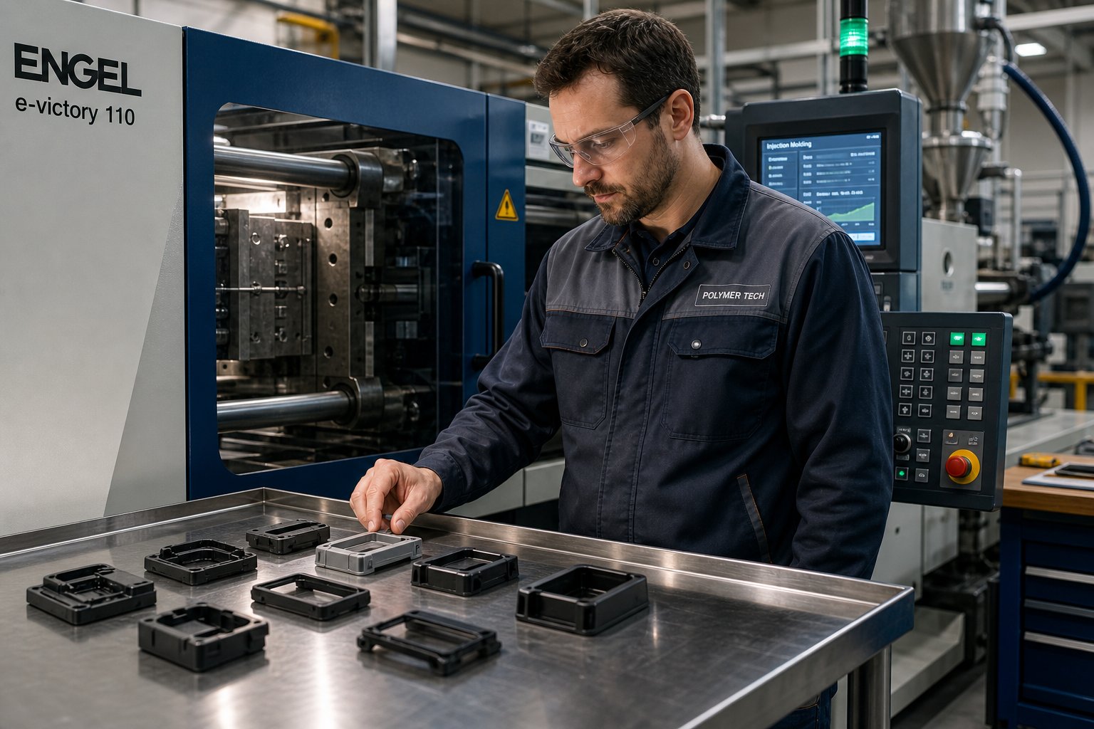
When Multiple Defects Collide and Parameters Conflict
Here's a scenario that every experienced molder recognizes: you increase pack pressure to eliminate sink marks on a thick rib section, and flash immediately appears at the parting line. Reduce the pack pressure to kill the flash, and the sinks come right back. You're trapped in a loop where every correction creates a new problem — and the temptation is to split the difference and accept mediocre parts. This is the real-world reality of injection molding problems that no simple defect chart prepares you for.
Multi-defect scenarios aren't unusual. They're actually the norm on complex parts with varying wall thicknesses, multiple gates, or tight cosmetic requirements. The key to breaking free isn't finding a single magic parameter — it's understanding why defect pairs conflict and which strategic levers can resolve one without triggering the other.
Common Conflicting Defect Pairs and Why They Occur
Conflicting defects emerge because many injection molding parameters sit on a spectrum where one end solves Problem A and the other end solves Problem B. Push too far in either direction, and you trade one failure for another. The most frequently encountered conflicts include:
- Sink marks vs. flash: Increasing pack pressure compensates for volumetric shrinkage, but if cavity pressure exceeds the mold's sealing capacity, material escapes at the parting line. This is the single most common conflicting pair in production.
- Jetting vs. short shots: Slowing injection speed prevents the melt from squirting through the gate, but reducing velocity too much allows the material to freeze before filling the cavity completely.
- Flow marks vs. burn marks: Raising melt temperature improves surface flow and eliminates hesitation lines, but pushing temperature too high degrades the polymer and generates gas that burns at last-to-fill locations.
- Warpage vs. long cycle time: Extending cooling time reduces distortion by allowing more uniform solidification, but every added second erodes production throughput and increases part cost.
These conflicts are not random. They occur because a single primary parameter — speed, pressure, or temperature — is being asked to do two contradictory jobs. The injection molding solution in each case lies not in finding a compromise midpoint on that one parameter, but in introducing a secondary parameter that breaks the trade-off entirely.
Prioritization Strategy for Multi-Defect Parts
When two defects appear simultaneously, the first question isn't "which is easier to fix?" It's "which one compromises part function?" A sink mark on a hidden internal surface is cosmetic. A weld line through a snap-fit latch is structural. Flash that requires hand-trimming is a cost issue. A short shot that leaves a sealing surface incomplete is a functional failure. Prioritize the structural or functional defect first, lock in the parameter correction that resolves it, and then address the cosmetic issue using a different parameter.
This hierarchy matters because structural fixes usually involve primary parameters — injection speed, pack pressure, melt temperature — that carry the largest secondary-defect risk. Cosmetic refinements, by contrast, often respond to secondary parameters that have a gentler influence on the overall process balance. Fixing in the wrong order means you'll constantly undo your first correction while chasing the second.
Secondary Parameters That Break the Trade-Off
Secondary parameters are the unsung heroes of multi-defect troubleshooting. When primary adjustments create a deadlock, these variables offer a way through without disturbing the structural fix you've already established:
- Mold temperature: Raising mold temperature improves surface replication and reduces flow marks without requiring the melt temperature increase that risks degradation. It's a lower-risk path to cosmetic improvement after a fill-speed adjustment has already locked in structural integrity.
- Gate size or geometry: Enlarging the gate reduces shear heating (addressing gate blush or shear splay) while simultaneously improving packing efficiency — which means you may be able to lower pack pressure slightly and eliminate flash without sacrificing sink-mark performance.
- Back pressure: Increasing back pressure improves melt homogeneity and reduces color streaking or unmelts, without significantly affecting fill dynamics or packing behavior. It's the go-to adjustment when plastic injection molding issues involve both cosmetic surface defects and unrelated structural concerns.
- Injection speed profile: Rather than a single fill speed, a staged velocity profile lets you run slowly through the gate (preventing jetting) and then accelerate through the cavity (preventing short shots). This eliminates the jetting-vs-short-shot conflict without compromising either outcome.
The table below maps the most common multi-defect conflicts, the parameter caught in the middle, and the resolution strategy that breaks each deadlock.
| Defect Pair | Conflicting Parameter | Resolution Strategy |
|---|---|---|
| Sink marks + Flash | Pack pressure | Optimize gate size to improve packing efficiency at lower pressure; verify clamp tonnage adequacy; inspect parting line for wear |
| Jetting + Short shots | Injection speed | Use a staged speed profile — slow initial speed through the gate, faster fill speed through the cavity |
| Flow marks + Burn marks | Melt temperature | Hold melt temperature at the burn threshold; raise mold temperature to improve surface flow without additional heat input |
| Warpage + Long cycle time | Cooling time | Balance coolant circuits to achieve uniform cooling; implement conformal cooling inserts in hot-spot areas to reduce time without uneven solidification |
| Splay + Short shots | Injection speed | Address splay root cause directly (dry material, reduce back pressure) rather than compensating with speed reduction that starves the fill |
Multi-cavity molds introduce yet another layer of complexity. When Cavity 3 shows sink marks while Cavity 7 flashes on the same shot, the problem is almost never a process parameter — it's a mold imbalance. Unequal runner lengths, inconsistent gate dimensions, or cooling circuit restrictions cause certain cavities to fill faster or pack more than others. Adjusting a machine-side parameter to fix one cavity's defect inevitably worsens the opposite defect in another cavity. The real injection molding defects and countermeasures here involve tooling corrections: balancing runner diameters, equalizing gate sizes, or addressing the specific cooling circuit that's starving one half of the mold.
When your process window narrows to the point where eliminating one defect immediately triggers another, the root cause is almost never the process itself — it's a mold limitation, a material shift, or a worn machine component squeezing the available operating range to an unsustainable margin.
That narrowing window is the diagnostic signal to stop adjusting parameters and start investigating the system. Is the parting line worn? Has a new resin lot shifted the melt flow index? Is the check ring leaking, robbing pack pressure from certain cavities? Answering these questions requires stepping back from the controller and examining the broader injection molding issues at the mold, material, and machine level. The resolution is rarely another parameter tweak — it's a corrective action in one of those upstream domains.
Material behavior, in particular, plays a much larger role in these multi-defect scenarios than many processors appreciate. Different resin families respond to the same parameter adjustment in fundamentally different ways — and understanding those differences is what separates a targeted fix from a frustrating loop of conflicting corrections.
How Resin Selection Changes Your Troubleshooting Approach
A parameter change that rescues a polypropylene part can destroy a polycarbonate one. Raising barrel temperature by fifteen degrees might eliminate flow marks in PP, but that same adjustment in PC could push the resin past its thermal stability threshold, producing widespread heat splay and embrittlement. The resin on the press fundamentally dictates which defect is most likely, which parameter to adjust first, and how aggressively you can adjust it. Ignoring material-specific behavior is one of the fastest ways to turn a single defect into three — and it explains why so many plastic injection molding defects recur when processors apply generic fixes without considering the polymer they're running.
The table below maps major thermoplastic families to their dominant failure modes, the critical parameter that matters most during troubleshooting, and the handling considerations that differentiate each material from the rest.
| Resin Family | Dominant Defect Risk | Critical Parameter | Special Handling Notes |
|---|---|---|---|
| Nylon (PA) | Moisture splay, drool, flash from hydrolytic degradation | Material moisture content (max ~0.18% / 1,800 PPM) | Highly hygroscopic; absorbs up to 8% moisture by weight in some grades; over-drying causes brittleness |
| Polycarbonate (PC) | Moisture splay, residual stress cracking, stress whitening | Material moisture content (max ~0.02% / 200 PPM) | Hygroscopic; very tight moisture tolerance; sensitive to chemical stress cracking from mold release agents |
| ABS | Splay, stress whitening at ejector pins, residual stress fractures | Melt temperature and mold temperature balance | Hygroscopic (max ~0.05-0.08%); amorphous — low shrinkage but prone to internal stress; sensitive to shear |
| Polypropylene (PP) | Warpage, sink marks, non-uniform crystallization | Cooling rate and mold temperature uniformity | Semi-crystalline; high shrinkage (0.010-0.025 in/in); cooling rate directly controls crystal structure and dimensional stability |
| Polyethylene (PE) | Warpage, sink marks, high shrinkage variation | Cooling circuit balance and pack pressure | Semi-crystalline; highest shrinkage range among common resins (0.015-0.040 in/in); non-hygroscopic but additives may introduce moisture sensitivity |
| POM (Acetal) | Voids, centerline porosity, formaldehyde outgassing | Melt temperature (narrow window — typically 10-15 degC range) | Semi-crystalline; high shrinkage (0.018-0.025 in/in); extremely narrow processing window; degrades rapidly if overheated; outgassing can cause burn marks |
| PEEK | Crystallization defects, poor surface finish, incomplete fill | Mold temperature (must be 150-200 degC for proper crystallization) | High-performance semi-crystalline; requires very high mold and melt temperatures; small parameter deviations create major defect shifts |
| PET | Moisture splay, acetaldehyde generation, crystallization haze | Material moisture content (max ~0.005% / 50 PPM) | Extremely hygroscopic; tightest moisture spec of common resins; amorphous PET must be crystallized before drying to prevent agglomeration |
Hygroscopic Resins and Moisture-Related Defect Patterns
Moisture is the single most common root cause of defects in plastic molding when processing hygroscopic resins — and the allowable thresholds are tighter than many processors realize. Polycarbonate tolerates only about 0.02% moisture before splay appears. PET demands an even stricter 0.005% maximum — roughly 50 parts per million. Nylon sits at roughly 0.18%, which sounds generous until you consider that certain nylon grades can absorb up to 8% moisture by weight when exposed to ambient humidity. Water bonds directly with the nylon polymer chain, making it particularly difficult to extract compared to surface moisture on non-hygroscopic resins.
The troubleshooting implication is direct: when you see splay on a hygroscopic resin, verify drying before touching the process. Check the dryer's dewpoint reading, confirm that residence time in the hopper meets the material supplier's recommendation, and measure actual moisture content with a moisture analyzer if one is available. A dryer that shows correct setpoints but has a failed desiccant bed or a leaking return-air hose delivers warm air without adequate dehumidification — the pellets feel hot but remain wet. As Plastics Technology's resin drying knowledge center notes, adding hygroscopic additives or colorants to an otherwise non-hygroscopic base resin like polyethylene can make the compound behave as a hygroscopic material, requiring dehumidified drying that the base resin alone would never need.
One often-overlooked nuance: over-drying can be just as damaging as under-drying for certain resins. Nylon processed too dry becomes brittle and can crack during ejection or in end-use. POM (acetal) degrades and generates formaldehyde gas when exposed to excessive heat or extended residence time in the dryer. Balancing drying time and temperature against the resin's thermal stability is part of the troubleshooting picture, not just an upstream material-handling step.
Crystalline vs. Amorphous Resin Troubleshooting Differences
The molecular structure of the polymer — whether it solidifies into an organized crystalline lattice or freezes as a disordered amorphous mass — changes which injection moulding defects dominate and which levers resolve them.
Semi-crystalline resins like PP, PE, nylon, and POM undergo a phase transition during cooling where polymer chains fold into organized crystal structures. This crystallization process is highly sensitive to cooling rate: cool one side of the part faster than the other, and that side crystallizes differently, shrinks more, and warps the geometry. Shrinkage values for semi-crystalline resins are significantly higher than for amorphous materials — PP runs 0.010 to 0.025 in/in compared to just 0.004 to 0.009 in/in for ABS. That higher shrinkage amplifies every cooling imbalance, every wall-thickness variation, and every packing inconsistency into a measurable dimensional defect. When troubleshooting warpage or sink marks on a semi-crystalline part, cooling circuit balance and mold temperature uniformity should be your first investigation, not pack pressure.
Amorphous resins like ABS, polycarbonate, and polystyrene have no crystallization event during cooling. Their shrinkage is lower and more predictable, which makes them better candidates for tight-tolerance applications. But amorphous resins carry their own vulnerability: internal stress. Because the disordered molecular chains freeze in whatever orientation the flow imposed on them, residual stresses lock into the part. These stresses manifest as stress whitening at ejector pin locations, environmental stress cracking when the part contacts certain chemicals, and delayed warpage that may not appear until hours or days after molding. Raising mold temperature allows some molecular relaxation before solidification and is the primary lever for reducing stress-related plastic molding defects in amorphous resins.
Engineering and High-Performance Resin Challenges
Engineering and high-performance resins like PEEK, PPS, and POM compress the acceptable processing window to a narrow band where small parameter errors produce dramatic defect shifts. PEEK, for instance, requires mold temperatures between roughly 150 and 200 degrees Celsius to achieve proper crystallinity — run the mold cooler, and the part exits with an amorphous surface layer that is weaker and chemically less resistant than a properly crystallized one. POM processes within a melt temperature range of only about 10 to 15 degrees before degradation begins, releasing formaldehyde gas that causes burn marks, voids, and a distinctive sharp odor.
These tight windows mean that the forgiving troubleshooting approach of "bump temperature up ten degrees and see what happens" can push the resin past its stability limit in a single adjustment. For high-performance resins, parameter changes should be made in smaller increments — two to five degrees for temperature, five to ten percent for speed or pressure — and each change needs several shots to stabilize before evaluation. Patience, not boldness, is the correct troubleshooting posture for plastic defects in injection molding with these materials.
Regrind adds another variable across all resin families. Reprocessed material introduces variability in flow behavior, moisture content, and thermal history that virgin resin doesn't carry. Each pass through the barrel degrades polymer chain length slightly, increasing melt flow and reducing mechanical properties. A batch running 25% regrind behaves differently from one running 10%, and a batch mixing first-pass regrind with third-pass regrind introduces unpredictable lot-to-lot swings. For semi-crystalline resins, regrind alters crystallization kinetics and can shift shrinkage values enough to push dimensions out of tolerance. For hygroscopic resins, regrind that wasn't dried immediately after grinding reabsorbs moisture faster than virgin pellets due to its higher surface-area-to-volume ratio. Controlling regrind ratio, documenting the number of reprocessing passes, and drying regrind separately before blending are not optional best practices — they are essential defenses against the kind of intermittent, hard-to-diagnose defects that consume hours of troubleshooting time.
Material behavior isn't a footnote to injection molding troubleshooting — it's the context that determines whether a given parameter adjustment is brilliant or disastrous. Matching your diagnostic approach to the resin on the press eliminates entire categories of trial-and-error experimentation. Yet even the most material-aware troubleshooter will eventually face the same question: how do you stop these defects from appearing in the first place? That shift from reactive correction to preventive strategy is where long-term process stability — and long-term cost savings — truly live.
Preventive Strategies and Plasticizing Component Maintenance
Fixing a defect is satisfying. Never seeing it again is profitable. Every hour spent troubleshooting in injection moulding is an hour that wasn't spent producing sellable parts — and the most effective injection molding troubleshooting guide isn't the one that teaches you to react faster, but the one that teaches you to prevent defects from appearing at all. Prevention rests on four pillars: documented process baselines, scheduled mold maintenance, disciplined material handling, and proactive plasticizing component inspection. Neglect any one of them, and you're not preventing problems — you're just postponing them.
Process Documentation and Baseline Parameter Sheets
A validated process that lives only in an operator's memory disappears the moment that operator calls in sick. Process documentation transforms tribal knowledge into a repeatable standard that any trained technician can follow — and more importantly, it creates a reference point for detecting drift before drift creates scrap.
Your baseline process sheet should capture every parameter that influences part quality, not just the obvious ones. Here's what belongs on it:
- Complete barrel temperature profile (rear, center, front, nozzle) with acceptable ranges, not just setpoints
- Injection speed profile by position or percentage of fill
- Pack pressure, hold time, and documented gate seal time from a gate seal study
- Cooling time, coolant inlet temperatures, and expected delta-T per circuit
- Back pressure, screw RPM, and decompression distance
- Cycle time target with acceptable upper and lower limits
- Cavity pressure curve shape (if in-mold pressure sensors are available) as a process signature
- Part weight range from the validation run, serving as a quick shot-to-shot consistency check
The critical habit isn't creating the document — it's using it. Every setup should begin with a parameter-by-parameter comparison against the baseline sheet. Every process change made during a production run should be logged with the reason, the result, and whether the baseline needs updating. Without this discipline, parameter drift accumulates silently across shifts until the process window collapses and defects erupt — seemingly out of nowhere.
After resolving any significant defect, validate the corrective action before declaring victory. Run a statistically meaningful number of shots — thirty to fifty at minimum — and measure critical dimensions across that sample. If your quality system supports it, calculate Cpk values for key features. Process validation best practices recommend a minimum Cpk of 1.33, indicating the process mean sits at least four standard deviations from the nearest specification limit. Document the corrective action, update the process sheet to reflect any changed parameters, and communicate the change to all shifts. A fix that isn't documented and verified is just a temporary patch waiting to unravel.
Mold Maintenance and Material Handling Protocols
Mold maintenance and material handling are the two preventive domains most often treated as afterthoughts — addressed only when a defect forces attention. Shifting to a scheduled, proactive approach eliminates a significant percentage of production-run issues before they reach the press.
For mold maintenance, build a schedule around shot count intervals rather than calendar dates, since a mold running three shifts wears faster than one running one:
- Every run: Wipe cavities and parting line surfaces; inspect for resin buildup or flash residue; verify waterline connections are secure and leak-free
- Every 10,000–25,000 shots: Clean vents thoroughly to remove carbon deposits; inspect ejector pins for galling, burrs, or bending; verify slide and lifter action for smooth operation
- Every 50,000–100,000 shots: Flush cooling circuits to remove scale and biofilm buildup that reduces heat transfer; inspect parting line surfaces for wear or crush; measure critical cavity dimensions against original steel specifications
- Annually or at major service intervals: Full disassembly, inspection, and preventive repair; replace worn seals, springs, and bushings; polish cavity surfaces as needed; apply rust inhibitor before storage if the mold will sit idle
Material handling deserves equal rigor. Many frustrating, intermittent defects — random splay, unexplained color shifts, occasional brittleness — trace back to material handling lapses rather than process or tooling problems. Observing injection molding safety precautions during material handling also protects both the product and the people on the floor:
- Verify dryer dewpoint and material residence time at the start of every shift, not just at startup
- Enforce documented regrind ratio limits (typically 15–25% maximum depending on resin and application) and track the number of reprocessing passes
- Store opened bags of hygroscopic resin in sealed containers; never leave hoppers uncovered overnight
- Maintain lot traceability — record which resin lot is running on which job so that any quality issue can be traced back to the material source
- Clean hoppers, loaders, and transfer lines between material changes to prevent cross-contamination
These protocols are straightforward, but consistency is what makes them effective. A checklist posted at the press and signed each shift transforms good intentions into verifiable habits. Many processors find that a downloadable reference — something like an injection molding defects causes and remedies pdf — helps standardize these procedures across shifts and facilities, but the document only works if the team actually follows it.
Plasticizing Component Inspection and Replacement Strategy
A worn screw or barrel is the most frequently overlooked root cause in production-run troubleshooting because the degradation is gradual — processors compensate with incremental parameter changes over weeks or months until the process is running on a patchwork of adjustments that mask the real problem.
Unlike a clogged vent or a moisture excursion, plasticizing wear doesn't produce a sudden, obvious defect. It creeps. The check ring leaks a little more each week. Flight clearance between screw and barrel widens by a few thousandths of an inch per month. Melt homogeneity degrades so slowly that the operator nudges back pressure up, then up again, then again — never realizing that the root cause isn't a process setting but a mechanical component that has exceeded its service life.
Build a plasticizing component inspection schedule around these checkpoints:
- Every 3–6 months: Run a check ring repeatability test — weigh twenty consecutive shots at a fixed shot size and calculate the variation. Weight spread exceeding 0.5% of nominal indicates check ring wear or damage
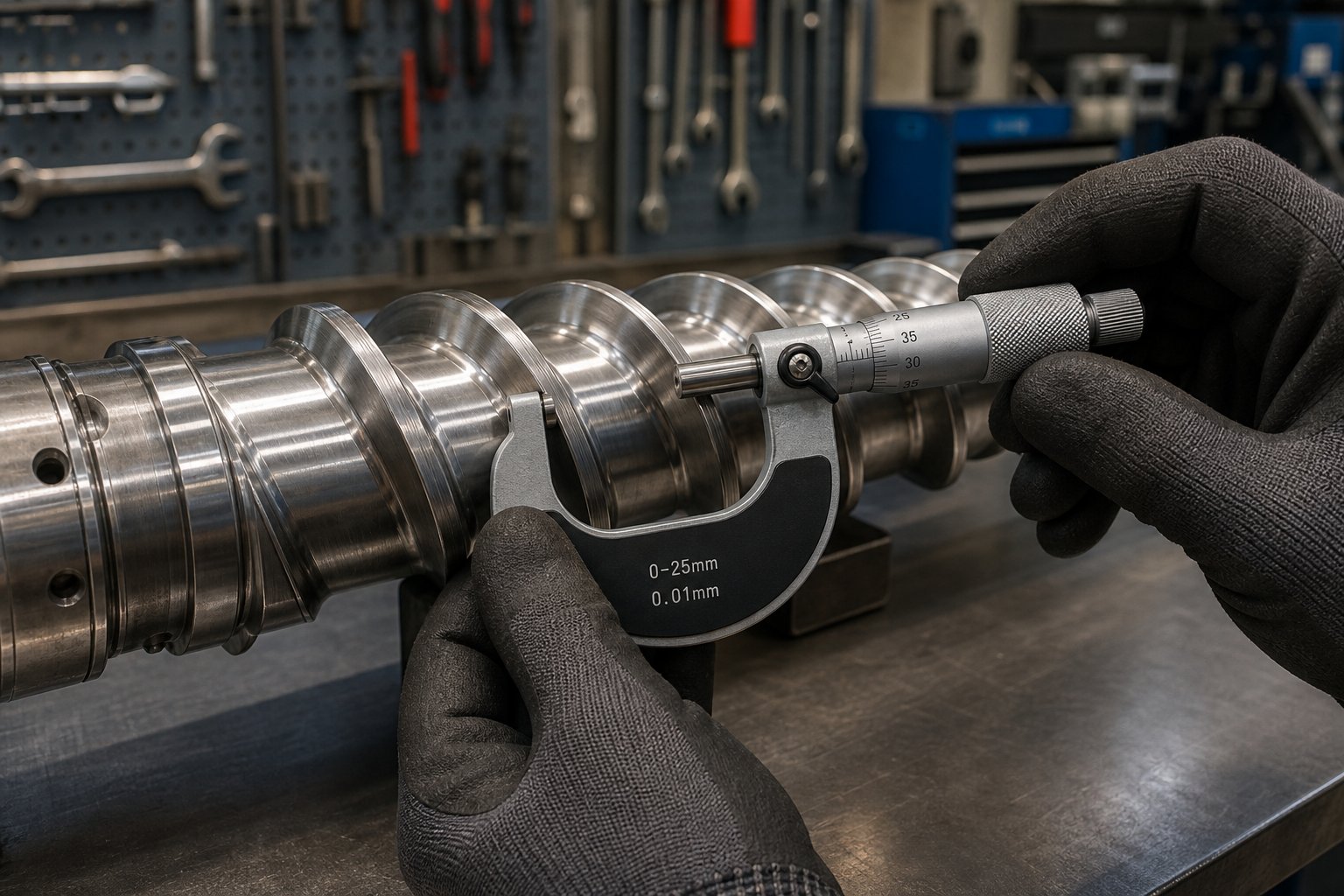
- Every 6–12 months (or sooner for abrasive/corrosive resins): Pull the screw and inspect visually for pitting, cracks, worn flight lands, and surface damage. Use a micrometer to measure screw flight outer diameter and compare against original specifications. A parallel test bar spanning two flights gives an accurate OD reading
- At screw pull: Measure barrel bore with a bore gauge at both ends and compare to nameplate or previous readings. Track measurements over time to build a wear profile that predicts when replacement will be needed, rather than reacting after quality has already suffered
- Ongoing: Monitor heater band performance — a failed band in the transition zone produces cold spots that cause unmelts, and the symptom looks like a material or screw design problem rather than a simple electrical failure. Verify thermocouple accuracy with a handheld probe periodically
The SPI Dimensional Guidelines provide reference thresholds for when a component is too worn to continue using. When measurements confirm wear beyond tolerance, no amount of process adjustment will restore consistent shot quality — the component needs replacement. For maintenance teams sourcing precision replacement screw barrels, custom plasticizing configurations matched to specific resin families, or technical guidance on optimizing screw geometry for their application, NANHAIYA's injection molding screw barrel solutions offer engineered components designed to restore shot consistency and extend the interval between replacements. Investing in properly specified plasticizing hardware is not a repair expense — it's a prevention strategy that pays dividends in reduced scrap, fewer troubleshooting interruptions, and a wider, more forgiving process window.
Injection moulding troubleshooting will always be part of the job — no process runs perfectly forever. But the balance between reactive firefighting and proactive prevention determines whether your team spends its time solving novel problems or re-solving the same ones every quarter. Document your baselines. Maintain your molds on a schedule. Handle your material with discipline. Inspect your plasticizing components before they quietly erode your process stability. These four pillars won't eliminate every defect, but they will ensure that when a defect does appear, it's genuinely new — and the systematic framework you've built throughout this guide will resolve it in minutes, not hours.
Injection Molding Troubleshooting FAQs
1. What are the most common injection molding defects and their root causes?
The most frequently encountered defects include splay (silver streaks from moisture, shear, or heat), burn marks (from trapped gas or excessive velocity), sink marks (from insufficient packing opposite thick features), short shots (from low pressure, restricted flow, or poor venting), flash (from overpacking or inadequate clamp force), and warpage (from uneven cooling or molecular orientation). Nearly all of these trace back to four root-cause categories: Machine issues like worn check rings or temperature drift, Mold issues like blocked vents or cooling imbalance, Material issues like excess moisture or contamination, and Method issues like operator inconsistency or parameter drift. Identifying the correct category before adjusting parameters prevents wasted time and secondary defects.
2. How do you systematically troubleshoot injection molding problems instead of guessing?
Effective troubleshooting follows a five-step diagnostic sequence: Observe the part closely for defect location, texture, pattern, and frequency across cavities. Categorize the defect as cosmetic or structural and assign it to a molding cycle phase (fill, pack, cooling, or ejection). Hypothesize using the 4M framework — Machine, Mold, Material, and Method — to generate a ranked list of likely causes. Test by adjusting only one parameter at a time in a deliberate direction while monitoring for secondary effects. Verify by running 30 to 50 consecutive shots to confirm the fix holds, then document the corrective action and update your process sheet. This method eliminates cascading side effects from random parameter changes and builds a repeatable skill applicable to any defect type.
3. How can you tell the difference between moisture splay and shear splay in injection molding?
The key distinction is pattern consistency. Moisture splay produces silver streaks that appear randomly across the part and shift location from shot to shot — the purge puddle often looks foamy or bubbly. Shear splay, by contrast, recurs in the exact same location on every shot because it originates from a fixed flow restriction or excessive velocity at a specific point in the mold. If streaks near the gate repeat identically each cycle, suspect shear from gate obstruction or high entry speed. If streaks move around unpredictably, check your dryer operation, dewpoint, and material moisture content before touching any machine parameter. This single observation eliminates roughly half the possible causes immediately.
4. Why does fixing one injection molding defect sometimes cause another defect to appear?
Conflicting defects occur because many process parameters sit on a spectrum where one end solves one problem and the other end solves a different one. For example, increasing pack pressure eliminates sink marks but can cause flash if cavity pressure exceeds the mold's sealing capacity. Slowing injection speed prevents jetting but may cause short shots if material freezes before filling. The solution is not to find a compromise midpoint but to use secondary parameters that break the trade-off — such as enlarging the gate to improve packing efficiency at lower pressure, using a staged injection speed profile, or raising mold temperature instead of melt temperature. Always prioritize structural defects over cosmetic ones and lock in that fix first before addressing secondary issues.
5. How often should injection molding screw and barrel components be inspected for wear?
A practical schedule includes running a check ring repeatability test every 3 to 6 months by weighing 20 consecutive shots and checking for weight variation exceeding 0.5% of nominal. Every 6 to 12 months — or sooner when processing abrasive or corrosive resins like glass-filled nylon or PVC — pull the screw for visual inspection and measure flight outer diameter with a micrometer against original specifications. At each screw pull, measure barrel bore with a bore gauge and track readings over time to predict replacement needs. Worn plasticizing components cause gradual degradation in shot consistency, melt homogeneity, and color mixing that processors often mask with incremental parameter changes. When measurements exceed tolerance, replacement with precision-engineered components — such as those available from NANHAIYA's injection molding screw barrel solutions — restores process stability far more effectively than further process compensation.
Written by
Nanhaiya Technical Team
Zhoushan Nanhaiya Plastic Machinery Co., Ltd.
The Nanhaiya technical team supports screw and barrel manufacturing projects through application review, technical communication, custom manufacturing coordination, and production and quality control.
Discuss Your Application
Related Articles
More insights on screw barrel technology and plastics processing.

What Nobody Tells You About Screw Barrel For Plastic Machine Design
Oct 10, 2026
Learn how screw barrel for plastic machine design affects melt quality, throughput, and wear life. Covers geometry, resin matching, troubleshooting, and sourcing.
Read Article
Single Screw Extruder for Sheet: Stop Guessing, Start Specifying
Oct 9, 2026
Learn how to specify a single screw extruder for sheet production. Covers screw geometry, resin-specific processing, troubleshooting, and maintenance best practices.
Read Article
PE Pipe Extruder Machine: What Datasheets Won't Tell You
Oct 9, 2026
Learn how a PE pipe extruder machine works, key specs explained, material grade selection, maintenance tips, and buyer guidance beyond the datasheet.
Read ArticleLooking for something else?
Search by material, symptom or product and jump straight to the relevant page.
These are navigation suggestions based on keyword matching — not a quotation, not a delivery commitment, and not a substitute for engineering review. Final specification is confirmed by our engineers against your drawings and processed material.
Need help with screw barrel selection?
Share your machine model, processed material and application. Our team can help with pricing and technical support.