

What Injection Molding Screws and Barrels Actually Do
Every plastic part you touch — from a bottle cap to a car dashboard panel — started as a handful of raw pellets. The components responsible for transforming those pellets into a precise, moldable melt are the heart of every injection molding machine.
Defining the Plasticizing Unit
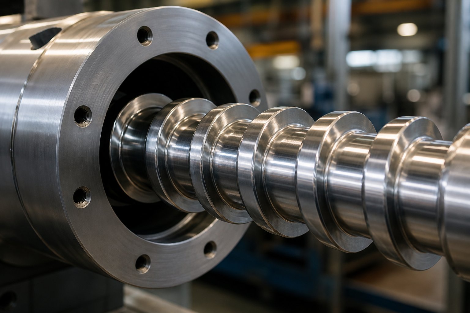
Injection molding screws and barrels form the plasticizing unit of an injection molding machine. Together, they receive solid plastic pellets, melt them through a combination of mechanical shear heating and conducted barrel heat, and deliver a homogeneous melt under controlled pressure into the mold cavity to form finished parts.
That definition sounds straightforward, but the engineering behind it is anything but simple. The injection molding screw rotates inside a heated barrel, and the friction generated between the polymer, the screw flights, and the barrel wall produces the majority of the heat needed to melt the resin. As Plastics Technology notes, polymers are excellent insulators, so conducted barrel heat alone cannot efficiently melt larger volumes of material. Shear heating — driven by screw rotation against barrel wall resistance — does the heavy lifting. Barrel heater bands then fine-tune melt temperature and compensate for thermal losses.
Why Screws and Barrels Must Be Understood as a System
Here is where most troubleshooting goes wrong. Maintenance teams often treat the screw and barrel as separate wear items, replacing one while ignoring the other. In reality, the barrel and screw function as a tightly coupled system. A worn screw spinning inside a new barrel — or a fresh screw dropped into an oversized bore — creates excessive clearance that allows melt to leak backward, destabilizes shot weight, and accelerates wear on the newer component. ENGEL's plasticizing technology team describes the plasticizing unit as "the heart of the injection molding machine," emphasizing that both material selection and process design require careful, interdependent attention to achieve good part quality.
Think of it this way: you would never replace just one brake pad on a caliper and expect balanced stopping performance. The same principle applies here.
Who This Resource Serves
This article is built for the people who actually specify, maintain, and purchase these components — maintenance engineers diagnosing inconsistent shot weights, plant managers evaluating total cost of ownership, and machine rebuilders selecting the right metallurgy for a customer's application. In the sections ahead, you will find a detailed walkthrough of screw geometry and zone functions, a comparison of screw types (general-purpose, barrier, and mixing designs), barrel construction and bimetallic lining technology, resin-specific metallurgy recommendations, quantitative wear measurement techniques, and a practical framework for making rebuild-versus-replace decisions.
The goal is simple: give you everything you need to make smarter specification and purchasing decisions in one place. And it all starts with understanding exactly what happens inside the barrel — zone by zone, flight by flight.
Anatomy of the Screw and Barrel Plasticizing System
Picture a plastic pellet dropping from the hopper into the barrel. Over the next few seconds, it will be conveyed, compressed, melted, mixed, and pressurized — all within a single rotating feed screw housed inside a precision-bored cylinder. Every inch of that journey is engineered. Understanding the anatomy of both components reveals exactly where wear starts, why defects develop, and how small dimensional changes cascade into big production problems.
The Three Zones of the Injection Screw
A standard injection molding screw is divided into three functional sections, each with a distinct channel depth and a specific job in the plasticizing process. Imagine the screw laid out from the hopper end to the nozzle end — the channel gets progressively shallower as the material moves forward.
- Feed zone: The deepest flights sit directly beneath the hopper opening. Their job is simple but critical — grab solid pellets and convey them forward reliably, shot after shot. The deep channel accommodates the bulk density of unmelted granules and the air trapped between them. Consistency here sets the baseline for everything downstream.
- Compression (transition) zone: The channel depth decreases gradually, squeezing the solid bed against the heated barrel wall. This mechanical compression, combined with barrel heat, initiates melting. Too aggressive a compression ratio can overshear heat-sensitive resins; too gentle, and unmelted particles survive into the metering zone.
- Metering zone: The shallowest section stabilizes the now-molten polymer. Its uniform channel depth ensures consistent output per revolution and brings the melt to a uniform temperature and viscosity before it reaches the screw tip. For most commodity resins, the plastic should be fully melted at this point — though high-viscosity or filled materials may still carry residual solids without specialized screw designs.
| Screw Zone | Primary Function | Approx. % of Screw Length | Key Processing Event |
|---|---|---|---|
| Feed Zone | Solid conveying | ~50% (typically 10 flights on a 20:1 L/D) | Pellets are received and augered forward; air is vented back through the hopper |
| Compression (Transition) Zone | Melting and compaction | ~25% (typically 5 flights) | Channel depth decreases, compressing the solid bed against the barrel wall to initiate melting |
| Metering Zone | Melt homogenization and pressure generation | ~25% (typically 5 flights) | Uniform shallow channel stabilizes melt temperature, viscosity, and output consistency |
Drag Flow and Pressure Flow Fundamentals
Why does plastic actually move forward inside the barrel? Two competing flow mechanisms govern output in the metering zone, and understanding them explains a surprising number of processing headaches.
Drag flow is the forward motion created by the screw's rotation against the stationary barrel wall. Imagine placing your hand flat on a table and dragging a book forward — the barrel wall acts like that stationary hand, and the rotating screw flights push melt ahead. Drag flow is proportional to screw speed, screw diameter, and channel depth.
Pressure flow works in the opposite direction. Back pressure from the mold, runner system, and nozzle resists the forward movement of melt, pushing some material backward through the screw channel. The net output — and therefore the screw recovery rate — is the difference between drag flow pushing forward and pressure flow leaking back.
This tug-of-war also generates shear heating. As the screw rotates, the polymer is sheared between the screw flight surfaces and the barrel bore. That mechanical energy converts directly into heat within the melt itself. In fact, shear heating typically contributes the majority of the thermal energy needed to melt the resin — barrel heater bands primarily fine-tune temperature and compensate for heat losses rather than doing the heavy melting work.
Barrel Construction and the Feed Throat
The barrel is far more than a hollow tube. Its construction directly influences melt quality, component longevity, and feeding reliability.
From the outside in, a typical barrel consists of:
- Outer steel housing: A heavy-walled steel cylinder machined to precise tolerances. It provides structural rigidity to resist injection pressures that can reach 30,000 psi or higher.
- Inner bore surface: The bore is finished to a tight diameter tolerance and a controlled surface finish. Depending on the application, this surface may be through-hardened via gas nitriding or lined with a centrifugally cast bimetallic alloy for enhanced wear and corrosion resistance.
- Heating bands and thermocouple ports: External band heaters are clamped around the barrel in discrete zones, each monitored by a thermocouple inserted through a drilled port. These zones allow independent temperature control from rear to front, matching the thermal profile to the resin's processing window.
- Feed throat: The opening where pellets enter the barrel from the hopper. This is arguably the most underappreciated component in the entire plasticizing system.
The feed throat in injection molding requires active cooling — typically with circulating water — to keep the area below the resin's softening point. If the throat runs too hot, pellets soften prematurely and stick together, creating what the industry calls "bridging." Injection molding expert John Bozzelli estimates that roughly 80% of the processes he encounters have issues related to feed-throat temperature control. The feed throat also serves as a vent, allowing air trapped between pellets and volatile off-gases to escape upward through the hopper. When bridging blocks this path, pressure can build dangerously — in severe cases, blowing melted plastic or even the hopper itself off the machine.
Sounds extreme? It happens more often than most shops admit. Controlling feed-throat temperature is one of the simplest, highest-impact process improvements available.
Screw Tip and Non-Return Valve Function
At the very front of the screw sits the injection molding screw tip and its non-return valve (also called a check ring). This assembly is the critical interface between the plasticizing phase and the injection phase — and it is one of the fastest-wearing points in the entire system.
During screw recovery, the non-return valve opens, allowing melt to flow forward past the screw tip and accumulate in front of the screw as the shot builds. When the screw pushes forward to inject, the valve must snap shut instantly, sealing like a syringe plunger to prevent melt from leaking backward through the screw flights.
Here is the problem: most conventional check valves seal over a relatively wide, flat contact area. If a glass fiber, a particle of contamination, or even a partially melted granule lands on that seat, the injection pressure can lift the ring off its seat — allowing melt to backflow. As Bozzelli explains, this backflow can push molten polymer all the way back into the feed section over repeated shots, eventually causing a dangerous Type 2 bridge. Stepped-angle or radiused-seat valve designs address this by concentrating the sealing force over a narrow contact line, dramatically improving shut-off reliability.
When the non-return valve wears, the symptoms are unmistakable: inconsistent cushion position, shot-to-shot weight variation, longer recovery times, and gradually worsening part quality. These are often the first measurable signs that the plasticizing unit needs inspection — and they highlight why treating the screw tip as a disposable afterthought is a costly mistake.
The geometry and materials of the screw determine how plastic melts. But not all screw designs are created equal — and the choice between a general-purpose, barrier, or mixing configuration can mean the difference between stable production and chronic defects.
Types of Injection Molding Screws Compared
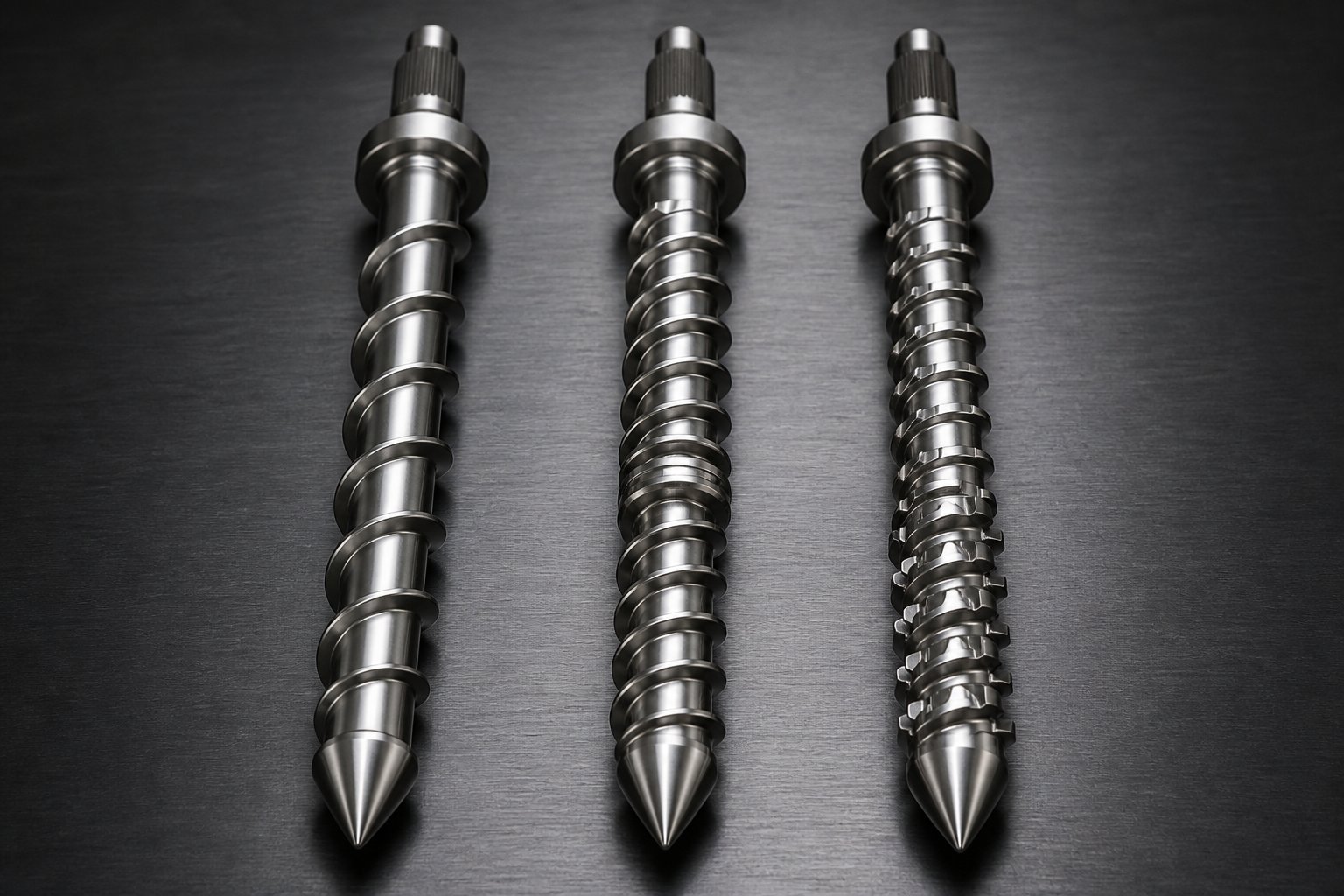
A general-purpose screw ships with nearly every injection molding machine sold. For a lot of shops, it never gets replaced with anything different — and for certain applications, that is perfectly fine. But when melt quality issues start showing up as splay, color streaks, unmelted particles, or inconsistent dimensions, the root cause is often a mismatch between screw design and the demands of the resin being processed. Choosing the right injection molding feedscrew is not about buying the most expensive option. It is about matching the screw's melting and mixing capabilities to what your application actually requires.
General-Purpose Screws and Their Limitations
The general-purpose (GP) screw — sometimes called a "metering" screw — features the classic three-zone design covered in the previous section: a deep feed zone, a tapered compression zone, and a shallow metering zone, all on a single primary flight. Its simplicity is its greatest strength. GP feed screws handle a wide range of commodity resins like polyethylene, polypropylene, and polystyrene without requiring custom engineering. They are cost-effective, readily available in standard sizes, and easy to replace. For shops running short production campaigns with frequent material changes, that versatility matters.
The limitations surface when you push a GP screw beyond its comfort zone. Because it relies on a single flight to compress and melt the solid bed, the solid-bed breakup phenomenon becomes a real problem at higher throughputs. Fragments of unmelted pellets break free from the solid bed, drift into the melt pool, and get carried forward into the shot. You will see these as "gels" or "unmelt specs" in finished parts — especially in clear resins where they are impossible to hide.
Filled materials compound the problem. Glass fibers and mineral fillers accelerate flight wear, widening the clearance between the screw and barrel. That increased clearance reduces the shear energy available for melting, creating a vicious cycle: more unmelts, more reject parts, and faster component degradation. Engineering-grade resins with narrow processing windows — nylon 66, POM, or PBT — also expose the GP screw's lack of melting precision. When you need tighter melt-temperature uniformity than a single-flight design can deliver, it is time to look at barrier or mixing configurations.
Barrier Screw Design and Melt Separation
Imagine you could physically separate the melted plastic from the still-solid pellets as they travel down the screw channel. That is exactly what a barrier screw does. A barrier screw introduces a secondary flight — the barrier flight — into the transition zone. This barrier flight is slightly undercut relative to the primary flight, creating a controlled gap. Molten polymer can flow over the barrier flight into a dedicated melt channel, but unmelted solids cannot pass through. The result is two separate channels running in parallel: one carrying the shrinking solid bed, the other accumulating an ever-growing pool of clean melt.
Why does this matter so much? In a conventional GP screw, the solid bed and melt pool share the same channel. As the solid bed breaks apart, unmelted fragments contaminate the melt stream. The barrier design eliminates this solid-bed breakup entirely. The practical benefits are significant:
- More uniform melt temperature — fewer hot spots and cold spots in the shot
- Higher melting capacity, which can translate to 15-20% faster recovery times
- Dramatically reduced unmelted particles, improving surface finish and mechanical properties
- Greater pressure stability during plasticizing
Barrier feedscrews become essential when you are processing semi-crystalline resins that have a sharp melting point and a narrow processing window. Materials like nylon, PET, HDPE, and polypropylene benefit enormously from the controlled melt separation. The design also shines in high-output applications where cycle time is king — the improved melting efficiency lets you run faster without sacrificing part quality.
One important caveat: not all barrier screw designs perform equally. The geometry of the barrier flight undercut, the rate at which the solid channel narrows, and the transition into the metering section all affect performance. A poorly designed barrier screw can actually overshear sensitive materials or create excessive pressure peaks. Working with an experienced feedscrew manufacturer who understands both the screw geometry and your specific resin is critical to getting the results you expect.
Dispersive vs Distributive Mixing Elements
Mixing screws address a different problem than barrier screws. Where barrier designs focus on melting efficiency and solid-melt separation, mixing elements focus on what happens after the plastic is melted — specifically, how uniformly additives, colorants, fillers, and blended resins are distributed throughout the melt stream. Two fundamentally different mixing mechanisms are at work, and understanding the difference helps you choose the right tool for the job.
Dispersive mixing applies high shear stress to break apart agglomerates — clumps of pigment, clusters of filler particles, or partially fused gel particles. Think of it like crushing a sugar cube: you need concentrated force to fracture the structure into its individual grains. Dispersive mixing elements achieve this by forcing the melt through narrow gaps or over restrictive flights, generating intense localized shear. The NC State Extension notes that wider kneading elements and reverse-pitch configurations promote dispersive mixing by maximizing shear rates and residence time in the mixing zone. These elements are ideal when processing resins with poorly dispersed pigment concentrates, glass-filled compounds where fiber bundles need separation, or recycled material containing contaminants.
Distributive mixing takes an already broken-down additive and spreads it evenly throughout the melt — without applying excessive shear. Imagine folding dough: each fold doubles the number of layers, creating uniformity through repeated reorientation rather than brute force. Distributive mixing elements use flow-splitting geometry — pins, slotted flights, or converging-diverging channels — to repeatedly divide and recombine the melt stream. The result is exponential mixing action with minimal heat generation. This is the right approach for color-critical applications, shear-sensitive resins like rigid PVC, or blended polyolefins where you need uniform property distribution without degrading the polymer chains.
Many modern injection molding screw designs combine both mixing types. A screw might pair a barrier melting section with a dispersive mixer to break agglomerates, followed by a distributive section to homogenize the melt before it reaches the screw tip. This layered approach delivers clean, uniform melt quality even in demanding multi-component applications.
Matching Screw Type to Your Application
So which screw type should you actually use? The answer depends on three factors working together: the resin you are processing, the quality standard your parts must meet, and the production volume driving your cost calculations.
For a shop running unfilled polypropylene or polyethylene in moderate volumes with standard cosmetic requirements, a general-purpose screw remains the practical, cost-effective choice. When you step up to semi-crystalline engineering resins, high-output production, or applications where unmelted particles are unacceptable, a barrier screw delivers measurable improvements in melt quality and cycle time. And when your process involves color concentrates, blended materials, filled resins, or any application demanding exceptional melt homogeneity, mixing elements — dispersive, distributive, or both — should be part of the conversation.
| Criteria | General-Purpose (GP) Screw | Barrier Screw | Mixing Screw |
|---|---|---|---|
| Melt Quality | Adequate for commodity resins; risk of unmelts at high throughput | Excellent — melt separation eliminates solid-bed breakup | Excellent — targeted homogenization of additives and colorants |
| Suitable Resin Types | PP, PE, PS, ABS, and other easy-flow commodity resins | Semi-crystalline resins (nylon, PET, HDPE, PP) and engineering grades | Color-critical, filled, blended, or recycled materials |
| Throughput Capability | Moderate — limited by single-flight melting capacity | High — 15-20% faster recovery vs GP in many applications | Varies — depends on mixing element design and shear tolerance of resin |
| Relative Cost | Lowest — standard off-the-shelf availability | Moderate to high — requires application-specific design | Moderate to high — often combined with barrier section for best results |
Keep in mind that the screw design only tells half the story. Even a perfectly optimized feedscrew will underperform — and wear out prematurely — if it is spinning inside a barrel with the wrong metallurgy for your resin. That match between barrel lining material and the chemical and mechanical demands of the polymer is where the next critical specification decision lives.
Barrel Materials and Bimetallic Lining Technology
Your screw design might be perfectly matched to the resin — barrier flights separating the solid bed, mixing elements homogenizing the melt — but none of that engineering matters if the barrel bore is wearing out underneath it. The injection molding barrel is not a passive container. It is an active participant in melting, pressure containment, and heat transfer. Its inner surface endures continuous contact with abrasive fillers, corrosive melt byproducts, and extreme pressures shot after shot. The metallurgy you choose for that bore surface determines whether the screw and barrel system holds tight tolerances for years or drifts out of spec within months.
Three primary barrel metallurgy categories dominate the industry, and each addresses a different balance of wear resistance, corrosion resistance, and cost. Understanding when each type is the right specification — and when it is not — is one of the most consequential decisions a plant engineer or procurement team will make.
Nitrided Steel Barrels and Their Applications
A nitrided barrel starts as a single piece of nitriding-grade alloy steel — most commonly 38CrMoAlA, EN-41B, or Nitralloy 135M — machined to precise bore dimensions and then surface-hardened through a gas or plasma nitriding process. During gas nitriding, the barrel is held at approximately 500-550 degrees Celsius in a nitrogen-rich atmosphere for an extended cycle. Nitrogen atoms diffuse into the steel surface, forming a hard case layer roughly 0.4 to 0.6 mm deep. The result is impressive surface hardness — typically 950 to 1,100 HV (approximately 65-70 HRC equivalent) — while the core beneath retains the toughness and ductility of the base steel at around 280-320 HB.
That combination of a hard surface and a tough core makes nitrided barrels an excellent, cost-effective choice for specific applications. When you are processing clean, unfilled commodity resins like virgin polyethylene, polypropylene, or general-purpose polystyrene at moderate production volumes, nitrided steel provides reliable performance for years. A well-manufactured nitrided barrel running virgin HDPE, for instance, can deliver five or more years of stable service at roughly half the capital cost of a bimetallic alternative.
The critical limitation is that thin case depth. Imagine a chocolate-covered almond — the hard shell is extremely thin relative to the soft interior. Once abrasive wear from glass fibers, mineral fillers, or contaminated regrind penetrates past that 0.5 mm hardened layer, the exposed soft core wears at a dramatically accelerated rate. There is no gradual degradation curve — the barrel goes from acceptable to failing rapidly once the case is breached. Industry data from field applications shows nitrided barrels lasting only 6 to 12 months when processing 30% or higher glass-fiber compounds, compared to 24-48 months or longer for barrels built with more aggressive wear protection.
For shops running unfilled commodity materials on moderate schedules, nitrided is the right engineering choice. Over-specifying a bimetallic barrel for clean polyolefin processing adds cost without meaningful operational benefit. The key is knowing exactly where that boundary sits for your specific application.
Bimetallic Barrel Linings Explained
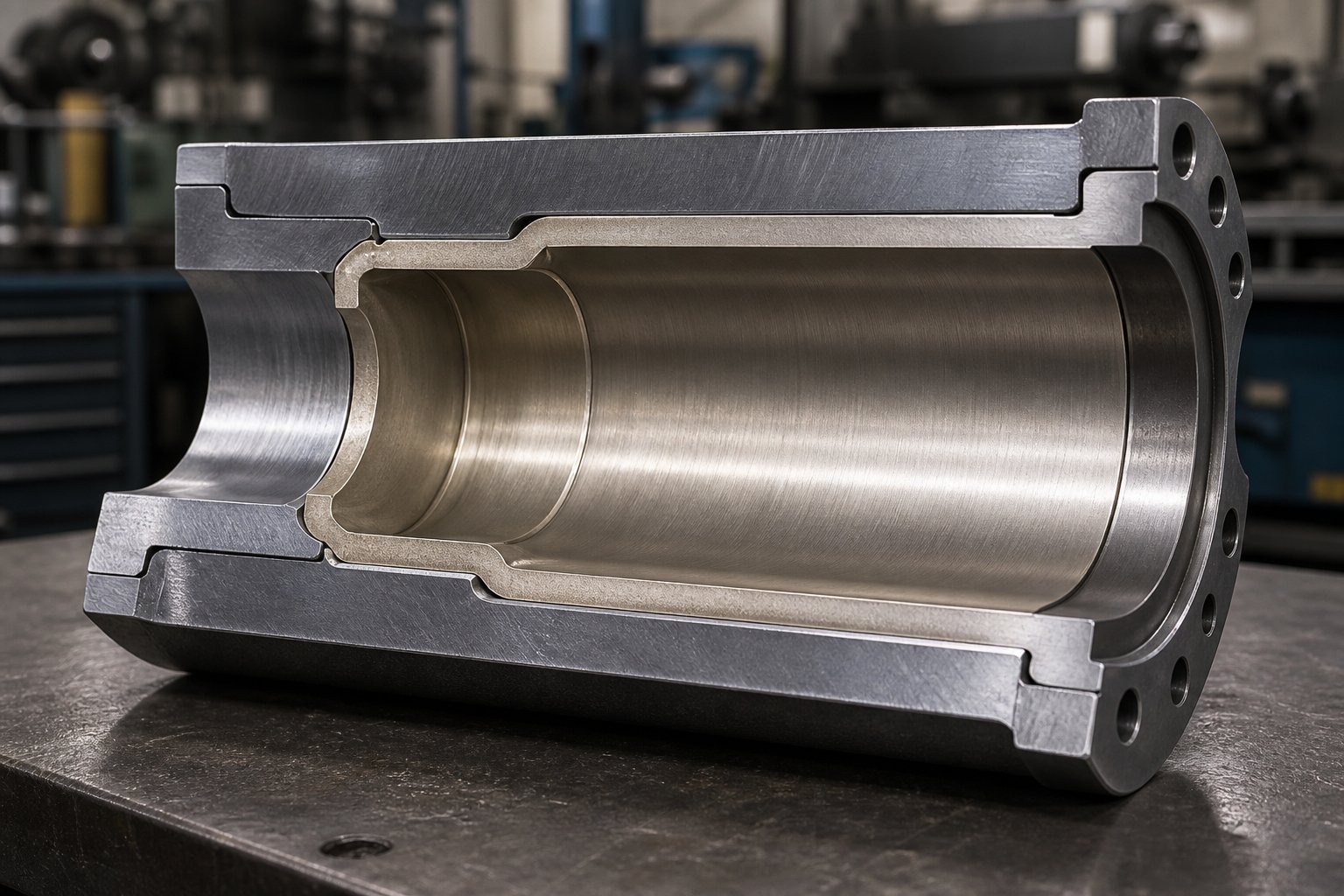
When the demands of the resin outstrip the protection a nitrided case can offer, bimetallic barrel technology provides the next level of defense. The concept is elegant: instead of relying on a thin hardened surface, a bimetallic injection molding barrel pairs a tough structural steel outer shell with a centrifugally cast, wear-resistant alloy inner lining that is 1.5 to 3.0 mm thick — roughly three to six times the effective wear depth of a nitrided barrel.
The centrifugal casting process is what makes this technology work. The barrel shell is placed in a high-speed rotating mold, and molten alloy is introduced inside. Centrifugal force drives the liquid alloy outward against the bore wall, producing a dense, pore-free lining with a true metallurgical bond to the steel substrate. Unlike manual lining methods or welded inserts, centrifugal casting eliminates internal voids and weak spots that could cause peeling or cracking under high-temperature, high-pressure operating conditions. The result is a homogeneous alloy layer with consistent hardness throughout its full thickness.
This matters on the shop floor because wear in a bimetallic barrel progresses through a material with stable, uniform hardness — not through a steep hardness gradient that collapses once the thin case is penetrated. Comparative testing shows centrifugally cast bimetallic barrels reducing average daily wear loss by roughly 85% compared to standard single-steel barrels when processing glass-fiber-reinforced materials.
Three primary alloy families are used for bimetallic linings, each engineered for a different dominant wear mechanism:
- Nickel-based alloys (Ni-Cr-B-W): These linings use a nickel matrix reinforced with chromium, boron, and tungsten carbides, reaching surface hardness of 60-65 HRC. Their standout property is corrosion resistance. When resins release chemically aggressive byproducts during processing — hydrochloric acid from PVC, corrosive gases from flame-retardant compounds, or acidic decomposition products from certain engineering plastics — nickel-based linings resist chemical attack that would eat through a nitrided surface. They also provide solid abrasive wear resistance, making them the go-to specification for PVC, CPVC, halogenated flame-retardant compounds, and any application where corrosion and abrasion act together.
- Cobalt-based alloys: Positioned between nickel and tungsten carbide options, cobalt-based linings deliver a balanced combination of wear resistance and corrosion resistance. They perform well in applications that see moderate abrasion combined with some chemical attack — for example, certain filled engineering resins or compounding operations that alternate between corrosive and abrasive material families. While less commonly specified than nickel or tungsten carbide options, cobalt-based alloys fill an important middle ground for shops that need versatility across multiple resin types without committing to a single-purpose metallurgy.
- Tungsten carbide alloys (WC-rich): For maximum abrasive wear resistance, tungsten carbide particles dispersed in a nickel or cobalt matrix create the hardest available lining, reaching 65-70 HRC or higher. Glass fibers, mineral fillers, and ceramic-loaded compounds act like continuous sandblasting against the barrel bore — and tungsten carbide is what stops that erosion. Testing by Milacron verified that tungsten carbide liners deliver the best overall wear life among lining options, making them increasingly popular for complex applications like glass-filled nylon, mineral-reinforced PBT, and heavily loaded engineering compounds. However, their testing also revealed that a precise balance of tungsten content is critical — too much tungsten in the liner can cause cracking during processing, while too little reduces wear resistance measurably.
Each alloy family addresses a specific set of operating conditions. Choosing the wrong one — or defaulting to the cheapest option — can leave your screw and barrel system exposed to exactly the wear mechanism your application generates most aggressively.
Matching Barrel Metallurgy to Resin Chemistry
The single most common specification mistake in barrel selection is treating metallurgy as a cost decision rather than an engineering decision. A procurement team comparing line-item prices between a nitrided barrel and a tungsten-carbide bimetallic barrel sees a 2-3x upfront difference and naturally gravitates toward the lower number. But the real cost calculation plays out over the barrel's entire service life — and the numbers often flip dramatically.
Consider glass-filled nylon processed through a standard nitrided barrel. The glass fibers continuously abrade the bore surface, and once they penetrate the thin nitrided case, the soft steel core is exposed. Field data consistently shows nitrided barrels failing in these applications within 6 to 12 months. A WC-rich bimetallic barrel running the same material can last 24 to 48 months or longer. When you factor in the cost of multiple barrel replacements, unplanned downtime, scrap produced during degraded operation, and the accelerated wear imposed on screws running in an oversized bore, the total cost per operating hour for the nitrided path can be nearly three times higher than the bimetallic alternative.
The same principle applies in corrosive environments. Running PVC compounds through a barrel without nickel-based corrosion protection is essentially accepting that hydrochloric acid byproducts will attack the bore from the inside. The barrel does not fail from mechanical wear — it fails from chemical erosion, often developing pitting and surface roughness that compromises melt quality long before the bore diameter reaches its wear limit.
Bore tolerances and surface finish also play a critical role in plasticizing efficiency, regardless of metallurgy. A properly finished injection molding barrel should maintain bore straightness within 0.015 mm per meter and a honed surface roughness of Ra 0.4 micrometers or better. Excessive roughness increases friction and can trap degraded polymer, while poor straightness creates uneven screw-to-barrel clearance that concentrates wear in localized zones. These specifications are just as important as the alloy selection itself — a perfectly chosen lining material in a poorly finished bore will still underperform.
| Barrel Type | Wear Resistance | Corrosion Resistance | Ideal Resin Families | Relative Cost Tier |
|---|---|---|---|---|
| Nitrided Steel (38CrMoAlA / Nitralloy 135M) | Moderate — 0.4-0.6 mm hard case only | Low to moderate | Unfilled PE, PP, PS, ABS; standard PVC at moderate output | 1.0x (baseline) |
| Nickel-Based Bimetallic (Ni-Cr-B-W) | Good — 1.5-3.0 mm alloy depth | Excellent | PVC, CPVC, flame-retardant compounds, halogenated resins, corrosive engineering plastics | 1.8-2.5x |
| Cobalt-Based Bimetallic | Good to high | Good | Mixed-application lines, moderate-fill engineering resins, multi-resin operations | 2.0-2.5x |
| Tungsten Carbide Bimetallic (WC-Rich) | Excellent — maximum abrasion protection | Moderate | Glass-filled nylon, mineral-filled PBT, heavily loaded compounds, ceramic-filled resins | 2.5-3.0x |
The barrel metallurgy decision, in practical terms, comes down to matching the dominant wear mode in your process — abrasive, corrosive, or both — to the lining architecture that resists it. An extrusion screw barrel faces similar choices in continuous processing, and the same alloy families apply. The real differentiator is how these metallurgy decisions interact with specific resin families and their unique combinations of filler content, processing temperature, and chemical behavior during melting — a mapping that separates good specifications from great ones.
Screw and Barrel Metallurgy Selection by Resin Family
Barrel lining categories and screw surface treatments exist for a reason — different polymers destroy plasticizing components in fundamentally different ways. A glass-filled nylon attacks through abrasion. PVC attacks through chemical corrosion. PEEK generates extreme heat and pressure that push even premium alloys to their limits. Matching the right metallurgy to the right resin is not a luxury upgrade — it is the single most effective way to control total cost of ownership for your injection molding screws and barrel system.
Yet most processors still default to the same general-purpose metallurgy across every machine in the plant. The result? Premature wear on demanding applications, wasted money on over-specified components for easy ones, and a constant cycle of reactive replacements that could have been avoided with a resin-driven specification approach.
Metallurgy decisions for injection molding screws and barrels should be driven by resin chemistry and production volume — never by upfront component price alone. The cheapest barrel on the purchase order is often the most expensive barrel on the plant floor.
Commodity Polyolefin and Styrenic Processing
Polyolefins like PE and PP, along with styrenics such as PS and ABS, are the friendliest resins your plasticizing unit will ever see. They melt at relatively low temperatures, generate minimal corrosive byproducts, and — when processed in unfilled form — impose primarily adhesive wear rather than aggressive abrasion or chemical attack.
For these materials, the dominant wear mechanism is slow, mechanical adhesive wear driven by normal screw-to-barrel contact over thousands of operating hours. The pressures are moderate, the melt viscosities are manageable, and the chemical environment inside the barrel is benign. This is the sweet spot for standard metallurgy. A nitrided steel barrel (38CrMoAlA with a 950-1,100 HV case) paired with a standard through-hardened or flame-hardened screw delivers reliable, cost-effective service. Flight hardening — typically induction or flame hardening to 50-55 HRC — provides adequate protection for the screw's outer diameter where it contacts the barrel bore.
There is one important nuance. When commodity resins include regrind containing contamination — metal fragments, abrasive dust, label adhesive residue — the wear profile shifts toward abrasion, even though the base resin is mild. Shops running high percentages of regrind through their injection molding screws should consider stepping up to a light hardfacing on the screw flights, such as Colmonoy 56, to guard against accelerated flight OD wear from contaminants that the virgin resin itself would never cause.
Styrenics like ABS and HIPS present a similar low-demand profile, though ABS can be mildly corrosive at elevated processing temperatures. Standard nitrided barrels handle ABS comfortably within normal processing windows. Just avoid extended residence times at high temperatures, which can generate volatile byproducts that begin to attack unprotected steel surfaces.
Glass-Filled and Mineral-Filled Compound Requirements
Here is where metallurgy selection separates the shops that plan from the ones that react. Filled compounds — glass-fiber-reinforced nylon, mineral-loaded PBT, glass-filled polycarbonate, and similar engineering materials — represent the most aggressively abrasive category in injection molding. Every pellet entering the barrel carries an internal payload of hard, angular particles that grind against the screw flights and barrel bore with every rotation.
The wear mechanism is overwhelmingly abrasive, and it is not subtle. Glass fibers (6-9 Mohs hardness) and mineral fillers like calcium carbonate, talc, and wollastonite act as continuous micro-cutting tools. As Stephen Surley of SpiraMelt Technologies explains, the severity of this abrasion depends heavily on particle size and shape — larger particles with sharper corners cause significantly faster wear than smaller, rounded ones. The feed section often takes the hardest hit because solid pellets provide limited lubrication compared to the molten polymer downstream, concentrating abrasive contact on the forwarding side of the flights.
Imagine running 30% glass-filled nylon 66 through a standard nitrided barrel. Those glass fibers — harder than the nitrided surface itself — chew through the 0.5 mm hard case in as little as six months of production. Once the soft core steel is exposed, bore wear accelerates exponentially. You will see recovery time creep upward, shot weights start drifting, and scrap rates climb — sometimes within weeks of the case breach. A tungsten-carbide-lined bimetallic barrel running the same compound routinely lasts three to five times longer because the 1.5-3.0 mm WC-rich lining maintains its hardness (1,200-1,400 HV) throughout the full depth of the wear zone.
On the screw side, standard flame-hardened flights cannot survive these conditions either. Injection molding screws for glass-filled and mineral-filled applications should be specified with tungsten carbide hardfacing on the flight OD — and in extreme cases, on the flight root as well. Stellite overlays (cobalt-chromium alloys at 40-55 HRC) offer an intermediate option that works well for moderate filler loading (15-25% glass) where the full expense of tungsten carbide hardfacing may not be justified.
The total cost of ownership math here is unambiguous. A plastic extruder screw or injection screw running heavily filled compounds through standard metallurgy will need replacement two to four times more frequently than one paired with matched wear-resistant metallurgy. When you add up the replacement component costs, unplanned downtime, labor hours, and scrap produced during the degraded-performance window before each replacement, the premium metallurgy pays for itself within the first service cycle in most high-volume operations.
Corrosive Resins Including PVC and Flame-Retardant Grades
Corrosion presents a completely different failure mode than abrasion — and requires a completely different metallurgical response. While abrasive wear removes material through mechanical grinding, corrosive attack dissolves or pits the metal surface through chemical reaction. The damage often starts invisibly, beneath the surface at grain boundaries, before erupting as pitting, intergranular cracking, or darkened residue on the screw and barrel surfaces.
PVC is the classic corrosive resin. During processing, PVC degrades thermally and releases hydrochloric acid (HCl) gas. At the elevated temperatures inside the barrel, this acid attacks unprotected steel aggressively. Even minimal wear from a PVC application can adversely affect quality because the increase in melt temperature from excessive shear accelerates HCl generation, which in turn accelerates corrosion — a destructive feedback loop. Flame-retardant compounds containing brominated or chlorinated additives generate similarly corrosive atmospheres, as do fluoropolymers that can release hydrofluoric acid (HF) at processing temperatures.
For these applications, nickel-based bimetallic barrel linings (Ni-Cr-B-W alloys like Colmonoy or similar formulations) are the standard specification. Their chromium and nickel content provides the chemical resistance needed to withstand acid attack while still offering solid abrasive wear protection. On the screw, stainless steel base materials (440C or 17-4 PH) or nickel-based hardfacing like Colmonoy 56 protect against the same corrosive environment. Chrome plating (50-80 microns thick) can provide a cost-effective barrier for mildly corrosive applications but lacks the durability for heavy PVC production or highly aggressive flame-retardant grades.
High-performance polymers like PEEK, PEI (Ultem), and PPS present a combined challenge: extreme processing temperatures (350-400+ degrees Celsius), significant chemical aggressiveness, and — in filled grades — severe abrasion from glass or carbon fiber reinforcement. These materials demand the highest tier of metallurgy on both the plastic extrusion screw and injection screw side. Tungsten carbide-hardfaced screws paired with nickel-tungsten carbide bimetallic barrels represent the typical specification. Even with premium metallurgy, component life in these applications is shorter than with commodity materials, making routine inspection intervals critical.
| Resin Family | Primary Wear Mechanism | Recommended Screw Treatment | Recommended Barrel Lining |
|---|---|---|---|
| Commodity Polyolefins (PE, PP) | Adhesive (mild mechanical) | Flame-hardened or induction-hardened flights | Nitrided steel (38CrMoAlA) |
| Styrenics (PS, ABS, HIPS) | Adhesive with mild corrosion risk at high temps | Flame-hardened flights; Colmonoy 56 optional for ABS | Nitrided steel |
| Engineering Resins — Unfilled (Nylon, PC, POM) | Moderate abrasive + mild corrosive | Colmonoy 56 or Stellite hardfacing | Nitrided or nickel-based bimetallic |
| Glass-Filled / Mineral-Filled Compounds | Severe abrasive | Tungsten carbide hardfacing on flight OD and root | Tungsten carbide bimetallic (WC-rich) |
| PVC, CPVC, Flame-Retardant Grades | Corrosive (HCl/HBr acid attack) | Colmonoy 56 or stainless steel screw (440C / 17-4 PH) | Nickel-based bimetallic (Ni-Cr-B-W) |
| High-Performance Polymers (PEEK, PEI, PPS) | Combined — extreme heat, corrosion, and abrasion in filled grades | Tungsten carbide hardfacing; premium tool steel base | Nickel-tungsten carbide bimetallic |
Getting the metallurgy right for your resin is the foundation — but it is only one dimension of the specification decision. The same screw metallurgy that excels in injection molding may perform quite differently on a plastic extruder screw running the identical resin in a continuous process. The mechanical demands of cyclic reciprocation versus steady-state rotation create a set of design differences that many processors overlook, especially when sourcing replacement components across both types of equipment.
Injection Molding vs Extrusion Screw Differences
Here is a scenario that plays out in maintenance shops more often than anyone likes to admit: a plant runs both injection molding machines and extruders, a screw wears out on one machine, and someone notices a spare screw sitting on the shelf with the same diameter. The diameters match. The material is similar. Why not just swap it in?
That shortcut can cost thousands in downtime, scrap, and damaged components — because an extruder screw and an injection screw are engineered for fundamentally different jobs, even when they look superficially similar. Understanding why they are not interchangeable protects you from a specification mistake that no amount of premium metallurgy can fix.
Cyclic vs Continuous Processing Demands
The core difference between the two applications comes down to motion. An extrusion screw rotates continuously in one direction, delivering a constant, uninterrupted melt stream through a die. It never stops, never reverses, and never changes its axial position inside the barrel. The design goal is steady-state output — a stable flow rate, uniform melt temperature, and consistent pressure measured in hours, not seconds.
An injection screw lives a completely different life. It rotates to plasticize and build a shot of molten material in front of the screw tip, then stops rotating and drives forward axially like a hydraulic ram to inject that shot into the mold. After injection, it holds pressure, decompresses, and then begins rotating again for the next shot. This cyclic reciprocation — rotate, translate forward, hold, decompress, repeat — imposes mechanical stresses and functional requirements that a continuous extrusion screw simply was never designed to handle.
Think of the difference this way: an extrusion screw is a marathon runner maintaining a steady pace. An injection screw is a sprinter who must also perform a standing long jump between every sprint. The physical demands shape every aspect of the design.
Key Geometry Differences in L/D and Compression Ratio
Because these two screws serve different processing philosophies, their geometries diverge in several critical ways. The length-to-diameter (L/D) ratio is one of the most visible differences. Extrusion screws typically use L/D ratios of 24:1 to 36:1 — and sometimes even higher for specialty applications. That extra length provides more residence time and barrel surface area for gradual, thorough melting and mixing in a continuous process. Injection screws, by contrast, commonly operate in the 18:1 to 24:1 range. The shorter length reflects the cyclic nature of the process: the screw only needs to plasticize enough material for a single shot during each recovery cycle, and the axial stroke required for injection limits how long the screw can practically be.
Compression ratios differ as well. An extrusion screw often employs a higher compression ratio — the ratio of channel depth in the feed zone to channel depth in the metering zone — because it must aggressively melt and compact material for continuous flow. Ratios of 3:1 to 4.5:1 are common for general-purpose extrusion work. Injection screws typically use shallower compression ratios, often in the 2:1 to 3:1 range, because the cyclic process demands less aggressive melting per revolution and because excessive compression can generate too much shear heat in materials that are sensitive to thermal degradation.
Feed section depth follows a similar pattern. Extrusion screws tend to have deeper feed channels to accept a high volume of pellets for the continuous process. Injection screws run shallower feed sections that match the shot-size and recovery-time requirements of the specific machine and mold combination. Additionally, extruder screws and barrels designed for continuous operation may incorporate more aggressive barrier flights and longer mixing sections — features that would be counterproductive or mechanically incompatible in a reciprocating injection application.
Why Screws Are Not Interchangeable Between Applications
Even when the nominal diameter matches, the differences between these two screw types run deep enough to make swapping them a serious engineering mistake. Here are the top design differences, listed in the order they are most likely to cause problems:
- Non-return valve accommodation: Every injection screw must interface with a non-return valve (check ring) at its tip to seal off backflow during injection. Extrusion screws have no provision for this — they terminate at the barrel end or connect to a breaker plate and die assembly. Installing an extrusion screw in an injection machine means no shot-size control and no injection seal.
- Axial load capacity: Injection screws are engineered to withstand the high axial thrust forces generated during injection — forces that can reach tens of thousands of pounds depending on machine tonnage and injection pressure. Extrusion screws experience primarily torsional loads from continuous rotation, and their shank and drive connections are not designed for the repetitive axial hammering of an injection cycle.
- L/D ratio mismatch: An extrusion screw's longer length will not physically fit in an injection machine barrel designed for a shorter L/D ratio. Even if length matches coincidentally, the zone proportions — how much of the screw is dedicated to feed, compression, and metering — are optimized for continuous flow, not cyclic shot building.
- Compression ratio mismatch: The more aggressive compression profile of a typical extrusion screw can overshear heat-sensitive injection molding resins, causing degradation, discoloration, or excessive melt temperature. Conversely, an injection screw's gentler compression may under-melt material in a continuous extrusion application, producing an inconsistent output stream.
- Barrel length and feed throat design: Injection molding barrels are shorter to match lower L/D screws and feature actively cooled feed throats optimized for cyclic pellet feeding. Extrusion barrels are longer, may include venting ports for volatile removal in two-stage screw designs, and use feed throat geometries designed for continuous gravity feeding rather than intermittent recovery cycles.
- Drive interface and spline design: The mechanical connection between the screw shank and the machine's drive system differs between injection and extrusion platforms. Injection machines use splined or keyed connections that transmit both rotational torque and axial thrust. Extrusion drives typically transmit rotation only, and the shank geometry often differs even at identical screw diameters.
Barrel specifications amplify these incompatibilities. Beyond the obvious length difference, injection barrels are built to contain the transient high pressures of each injection stroke — pressures that spike well above the steady-state operating pressures inside an extrusion barrel. The wall thickness, flange connections, and pressure ratings reflect this cyclic loading. Vented extrusion barrels, which include atmospheric or vacuum vent ports for removing moisture and volatiles during continuous processing, have no equivalent on standard injection barrels, where the hopper and feed throat serve as the primary venting path during the brief recovery phase.
The bottom line is simple: these components may share a family resemblance, but they are purpose-built for their respective processes. Specifying the correct screw type is just as critical as choosing the right metallurgy or flight geometry. And when either component — injection or extrusion — starts wearing beyond tolerance, the processing symptoms follow a predictable pattern that can be measured, diagnosed, and acted on before quality collapses.
Measuring Screw and Barrel Wear with Diagnostic Precision
Suspecting wear and proving it are two very different things. You might notice recovery time creeping upward or shot weights drifting wider than they used to — but without hard numbers, you are guessing. Guessing leads to premature replacements that waste money or, worse, delayed replacements that destroy part quality and damage other machine components. Quantitative measurement turns screw and barrel wear from a vague concern into a data-driven maintenance decision.
Every plastic processor should include routine inspection of plasticizing components in their maintenance program. As Adams Engineers emphasizes, the best maintenance programs have regularly scheduled inspections where components are measured over time, creating a wear profile that identifies the lifespan of each component. That profile lets you plan replacements before quality suffers — instead of reacting after scrap rates spike.
Barrel Bore Gauging Techniques
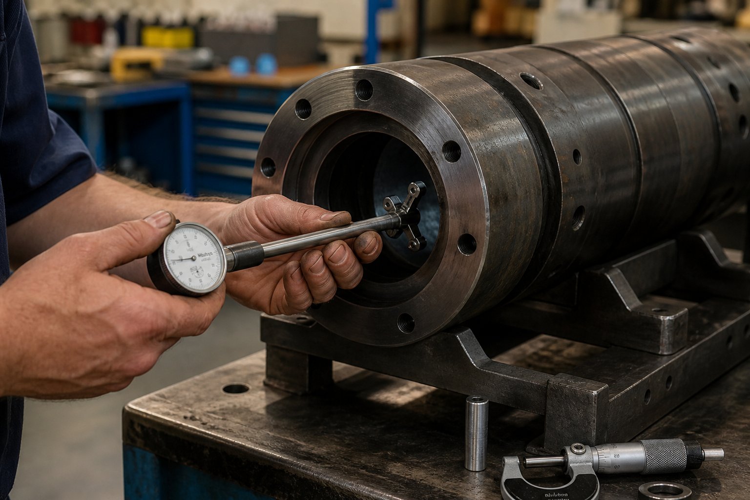
Barrel bore measurement is conceptually simple but demands careful technique to produce reliable data. The tool of choice is a telescoping bore gauge (sometimes called a snap gauge) used in combination with an outside micrometer, or — for higher precision — a dedicated bore micrometer that reads the internal diameter directly.
Here is the process. With the screw removed and the barrel cleaned of residual polymer, insert the bore gauge at multiple positions along the barrel length. At minimum, take readings at the feed end, at the midpoint of the transition zone, and near the discharge end. At each position, measure in at least two perpendicular orientations — vertical and horizontal — because wear is rarely uniform around the circumference. Gravity, screw deflection, and resin flow patterns all create preferential wear zones, often concentrated on the bottom of the bore where the screw's weight presses the flights against the barrel wall during operation.
Compare each reading against the barrel's original bore diameter specification, which is typically stamped on the barrel flange or recorded in the machine documentation. The critical number is the diametral clearance — the difference between the barrel bore ID and the feedscrew flight OD. For a new injection screw and barrel assembly, this clearance is intentionally tight. Industry clearance guidelines provide reference values by screw size:
| Screw Size | New Clearance (Diametral) | Worn — Monitor Closely | Max Wear — Replace |
|---|---|---|---|
| 1" (25 mm) | 0.003 - 0.005" | 0.013 - 0.018" | 0.019 - 0.020" |
| 1.5" (40 mm) | 0.004 - 0.008" | 0.014 - 0.020" | 0.022 - 0.025" |
| 2.5" (60 mm) | 0.005 - 0.010" | 0.016 - 0.021" | 0.028 - 0.030" |
| 3.5" (90 mm) | 0.009 - 0.012" | 0.021 - 0.030" | 0.036 - 0.037" |
| 4.5" (120 mm) | 0.010 - 0.013" | 0.030 - 0.031" | 0.039 - 0.050" |
When diametral clearance reaches the "worn" range, processing symptoms become noticeable and the component should be monitored closely at shortened intervals. Once clearance hits the maximum wear threshold, continued operation risks unacceptable part quality and accelerated damage to the mating component. These values serve as general guidelines — your specific resin, production intensity, and quality requirements may tighten or loosen the acceptable range.
Screw Flight and Non-Return Valve Inspection
Measuring the injection screw requires pulling it from the barrel, purging off residual resin, and placing it on a clean, flat work surface. Before reaching for a micrometer, start with a visual inspection. Roll the screw slowly and look for obvious damage — cracks, pitting, galling on the flight edges, or discoloration indicating localized overheating. If you have access to a granite surface table, roll the screw across it and watch for wobble, which reveals bending or bowing. A bent feedscrew creates uneven barrel contact that concentrates wear on one side — explaining those asymmetric bore wear patterns you might find during barrel bore measurement.
For dimensional measurement, use an outside micrometer to check the screw flight outer diameter at regular intervals along the screw's length — typically every five flights or at standardized positions that correspond to the feed, transition, and metering zones. A practical tip from Adams Engineers: use a parallel test bar spanning two flights as a reference surface, then measure across the flight OD and the test bar to determine the true outer diameter. This technique eliminates the measurement error that comes from trying to balance a micrometer on a single narrow flight edge.
Beyond flight diameter, inspect:
- Flight edge condition: Sharp, square flight edges are essential for effective wiping of the barrel bore. Rounded or feathered edges indicate progressive wear that reduces the screw's ability to generate pressure and convey material efficiently.
- Channel root surface: Look for scoring, erosion, or pitting in the root of the screw channel. Root wear is common in applications running highly abrasive filled compounds.
- Non-return valve (check ring): This is one of the fastest-wearing components in the plasticizing system. Check the seating surface of the ring and its mating seat on the screw tip for grooves, scoring, or uneven contact patterns. Even a small amount of seat wear allows melt to leak past during injection, causing cushion inconsistency and shot-weight variation. Replace the non-return valve assembly any time you see visible seat damage — it is inexpensive insurance against a cascade of quality problems.
Record every measurement and date it. Over multiple inspection cycles, these numbers build the wear profile that transforms maintenance from reactive to predictive — telling you not just where you are, but how fast you are getting there.
Interpreting Wear Patterns and Processing Symptoms
Raw numbers tell you how much wear has occurred. The pattern of that wear tells you why — and that diagnostic insight is often more valuable than the measurements themselves.
Wear concentrated in the feed zone — especially on the forwarding side of the screw flights — points directly at abrasive filler damage. Glass fibers, mineral fillers, and contaminated regrind are most destructive here because the material is still solid. Unmelted pellets provide almost no lubrication, so hard filler particles grind against the screw flights and barrel bore with maximum force. If your barrel bore measurement shows the feed section opening up faster than downstream zones, abrasion is your primary wear driver, and you likely need harder flight treatments or a more wear-resistant barrel lining.
Wear concentrated in the metering zone suggests a different culprit: corrosive attack. By the time the polymer reaches the metering section, it is fully molten and at its highest temperature. Thermally sensitive resins — PVC, flame-retardant grades, certain acetals — release aggressive byproducts at these temperatures. If the metering zone shows pitting, discoloration, or surface roughness while the feed section remains relatively clean, corrosion is driving the failure, and upgrading to corrosion-resistant metallurgy (nickel-based bimetallic barrel, stainless or nickel-hardfaced screw) is the correct response.
Uniform wear along the entire length typically indicates adhesive wear from normal operation — metal-to-metal contact between the screw flights and barrel bore over extended service hours. This is the expected wear mode for unfilled commodity resins and usually progresses slowly enough that scheduled replacement intervals can be predicted accurately from the wear profile data.
Regardless of the pattern, the processing consequences of excessive screw-to-barrel clearance follow a predictable progression. As the gap widens, you will notice:
- Inconsistent shot weight — melt leaks backward past worn flights during injection, reducing the effective shot volume
- Longer screw recovery time — increased clearance reduces the screw's pumping efficiency, requiring more revolutions to build the same shot size
- Poor melt homogeneity — wider clearance reduces shear input into the polymer, resulting in temperature variation and unmixed regions in the melt stream
- Increased energy consumption — the machine compensates for reduced plasticizing efficiency by running longer recovery cycles and higher screw speeds, consuming more motor energy per shot
- Cushion instability — the non-return valve cannot seal effectively when the check ring and its seat are worn, causing the cushion position to drift shot to shot
- Visible part defects — splay, flow marks, shorts, and dimensional variation that worsen progressively as clearance continues to grow
Wear in one component always accelerates wear in the other. A worn screw spinning inside a new barrel concentrates contact stress on narrower areas, scoring the fresh bore surface. A new screw installed in a worn barrel runs with excessive clearance from day one, generating vibration and misalignment that erode the new screw's flights faster than normal. The screw and barrel must always be evaluated — and replaced — as a system.
This systems principle is the thread running through every maintenance decision. Measuring both components at the same time, interpreting their wear patterns together, and making replacement decisions as a matched pair is the only approach that delivers predictable, cost-effective service life. The question that naturally follows is not just when to act on these measurements — but how: should you rebuild, re-coat, or replace outright? That economic calculation depends on how much usable material remains and what your application demands going forward.
Screw Barrel Maintenance Schedules and Rebuild vs Replace Decisions
You have the measurements. You understand the wear patterns. The bore gauge readings show clearance creeping toward the action zone, and the screw flight OD numbers confirm what the processing symptoms have been hinting at for weeks. The critical question shifts from "is something wrong?" to "what do I do about it — and when?"
This is where disciplined screw barrel maintenance separates high-performing plants from reactive ones. A structured inspection program catches wear early enough to plan your response — rebuild, re-coat, or replace — on your schedule, not the machine's. And the economics of each path depend heavily on how much usable material remains, what resin you are running, and whether you treat the screw and barrel as the matched system they are.
Setting Inspection Intervals by Application Severity
Not every machine needs the same inspection frequency. A press running unfilled polypropylene on a single shift wears its plasticizing components at a fraction of the rate of a machine running 30% glass-filled nylon around the clock. Treating both the same — either over-inspecting the easy application or under-inspecting the demanding one — wastes either labor hours or production quality.
A practical framework ties inspection intervals to three variables: resin abrasiveness, production intensity, and the criticality of part quality requirements.
- Low severity (unfilled commodity resins, single-shift operation, standard quality tolerance): Full screw pull and bore measurement every 4,000-6,000 operating hours, or annually — whichever comes first. Monthly process monitoring (recovery time trending, shot-weight consistency checks) serves as a leading indicator between physical inspections.
- Moderate severity (lightly filled engineering resins, two-shift operation, tighter dimensional requirements): Full inspection every 2,000-4,000 operating hours. Increase process monitoring to weekly. Non-return valve condition should be checked at each inspection — these components wear faster than the screw body in moderately abrasive environments.
- High severity (heavily glass-filled or mineral-filled compounds, 24/7 operation, precision or medical-grade quality standards): Full inspection every 1,000-2,000 operating hours. Weekly bore gauge spot-checks at the feed section — the zone that takes the hardest abrasive hit — can catch accelerating wear before it reaches the replacement threshold. As maintenance data from production environments confirms, machines running glass-filled resins on continuous schedules hit "annual" mileage in roughly five to six calendar months. Wall-clock schedules miss this entirely.
- Corrosive resins (PVC, flame-retardant grades, fluoropolymers): Inspection every 2,000-3,000 hours with special attention to the metering zone and barrel discharge end, where corrosive byproducts concentrate at peak temperatures. Visual inspection for pitting and discoloration is as important as dimensional measurement in corrosive environments.
The key principle: tie your inspection triggers to operating hours or shot counts, not calendar dates. A machine that runs two shifts of glass-filled nylon accumulates wear four times faster than a single-shift press running virgin PE. Calendar-based schedules cannot account for that difference — hour-based ones can.
A Practical Inspection Checklist
When the scheduled inspection arrives, a written checklist ensures nothing gets skipped under production pressure. Imagine your best maintenance technician is unavailable and a less experienced team member handles the pull. Without a standardized procedure, critical measurements get missed, and the data trail that supports your rebuild-or-replace decision has gaps in it.
Here is a working checklist that covers the essential data points for every screw pull and barrel inspection:
| Inspection Item | Method | What to Record | Action Trigger |
|---|---|---|---|
| Barrel bore diameter | Telescoping bore gauge + outside micrometer at feed, transition, and metering zones; measure in two perpendicular orientations at each point | Bore ID at each position (mm or in.); calculate diametral clearance vs. original spec | Clearance exceeding "monitor closely" threshold for your screw size (see clearance table from diagnostic section) |
| Screw flight OD | Outside micrometer at every 5 flights; use parallel test bar for accuracy | Flight OD at each position; note any localized wear patterns | Flight OD reduction exceeding 50% of original clearance allowance |
| Screw straightness | Roll screw on granite surface table; check for wobble or visible bowing | Pass/fail; note location and severity of any deviation | Any visible bend — a bent screw accelerates barrel bore wear asymmetrically |
| Flight edge condition | Visual and tactile inspection along full screw length | Sharp/square vs. rounded/feathered; note affected zones | Rounded edges in metering zone indicate loss of wiping efficiency |
| Non-return valve seat | Visual inspection of check ring and mating seat; check for grooves, scoring, uneven contact | Seat condition rating (good / worn / replace); measure ring-to-seat gap if possible | Any visible scoring or groove — replace the assembly |
| Heater band resistance | Megohmmeter or multimeter on each barrel zone heater | Resistance value (ohms) per zone; compare to manufacturer spec | Resistance deviating more than 10% from spec indicates partial element failure |
| Thermocouple calibration | Compare each barrel thermocouple reading against a calibrated reference probe at operating temperature | Deviation from reference (degrees C or F) per zone | Deviation exceeding ±3°C — recalibrate or replace the thermocouple |
Record everything with dates and operating hours. Over two or three inspection cycles, you will have a wear rate — inches or millimeters of clearance change per thousand hours — that lets you predict when the next rebuild or replacement will be needed. That predictability is worth far more than the labor cost of the inspection itself.
Rebuild vs Re-Coat vs Full Replacement Economics
When the numbers say it is time to act, three paths are on the table. Each has a place in a smart maintenance strategy — and each has conditions where it makes sense and conditions where it wastes money.
Rebuild means restoring the existing components to serviceable condition. For screws, this typically involves welding new hard-facing material onto worn flight crests (PTA welding with tungsten carbide or stellite alloy), grinding the flights back to original OD tolerance, straightening if necessary, and polishing the full length. For barrels, rebuilding may include boring the barrel to true roundness on a horizontal boring machine, then honing the bore to a slightly oversized finished dimension — paired with a new screw ground to match the larger bore. Refurbishment specialists like Nan Yun Industrial note that PTA welding on a white steel base repair can more than double the service life of a screw compared to the original nitrided surface. Rebuilds typically cost 40-60% of new component pricing and restore 90-95% of original performance when the base material is sound.
The critical caveat: a screw should never be refurbished more than three times. Each welding cycle introduces heat into the base metal, degrading its grain structure and increasing the risk of delamination between the hard-facing and the substrate. After the third rebuild, the likelihood of premature failure rises sharply — and the economics no longer favor rework over replacement.
Re-coat or re-line addresses the surface protection layer without rebuilding the full component geometry. On the screw side, this might mean applying a new hard chrome plating (50-80 microns) for corrosion protection or adding a new tungsten carbide spray coating to flight OD surfaces. On the barrel side, it can mean installing a new centrifugally cast bimetallic liner inside the existing steel shell — essentially giving a structurally sound barrel a completely new wear surface. This option sits between a rebuild and full replacement in both cost and expected service life. It makes the most sense when the barrel's outer shell and heating provisions are intact but the bore surface is beyond simple honing, or when you want to upgrade metallurgy (for example, converting a nitrided barrel to bimetallic protection because your resin mix has shifted toward more abrasive compounds).
Full replacement is the right call when the base material is too compromised for rework — excessive bowing, deep pitting, fatigue cracking, or a screw that has already been rebuilt multiple times. It is also the correct choice when the replacement represents an opportunity to upgrade screw geometry (switching from a GP to a barrier design) or barrel metallurgy (stepping up to a tungsten carbide lining for a new glass-filled application). The upfront cost is highest, but so is the expected service life and the confidence in first-shot performance consistency.
For processors sourcing full replacements, the quality of the manufacturing matters as much as the metallurgy specification on paper. Bore straightness, surface finish, alloy composition consistency, and dimensional accuracy to the specific machine platform all determine whether the new components deliver their rated service life — or fall short. Manufacturers like NANHAIYA, who specialize in custom injection molding screw and barrel manufacturing matched to specific machine and application requirements, serve exactly this need for injection molding factories and machine rebuilders who cannot afford to compromise on fit or material quality.
| Condition Indicators | Recommended Action | Estimated Cost Tier | Expected Service Life Extension |
|---|---|---|---|
| Flight OD worn but base metal sound; barrel bore within honing range; fewer than 3 prior rebuilds on the screw | Rebuild — re-hardfacing flights (PTA weld), bore honing, non-return valve replacement | 40-60% of new component cost | 70-95% of original service life per rebuild cycle; diminishing returns after 2nd rebuild |
| Barrel shell structurally sound but bore surface beyond honing limits; or metallurgy upgrade needed for new resin requirements | Re-line — install new centrifugally cast bimetallic liner in existing barrel shell; re-coat screw flights as needed | 55-75% of new component cost | Near-new performance; equivalent to new barrel lining service life for the selected alloy |
| Base metal compromised (cracking, deep pitting, excessive bowing); screw previously rebuilt 3+ times; or upgrading screw geometry/barrel metallurgy for new application | Full replacement — new matched screw and barrel set to application-specific specifications | 100% (baseline for new components) | Full rated service life; opportunity to specify upgraded metallurgy and geometry for improved performance |
One decision error shows up more often than any other — and it ties directly back to the systems principle that runs through this entire article. A plant replaces a worn screw but drops it into the existing barrel, or installs a new barrel and keeps the old screw. The mismatch creates excessive clearance from day one. The new component compensates for the old one's wear by absorbing uneven contact stress, and its service life shortens dramatically. Rebuilds typically restore 90-95% of original performance when done properly — but only when both components in the system are addressed together. Replacing one worn part while ignoring its partner is not a cost saving. It is a guarantee that you will be back in the same position in half the time.
The rebuild-or-replace decision is ultimately the last step in a longer chain of questions. What resin are you running? What quality does your customer demand? How many hours per year does this machine operate? Are you experiencing screw wear, barrel wear, or both? And is this replacement an opportunity to upgrade — not just restore — your plasticizing performance? Answering those questions in sequence transforms the specification from a reactive purchase order into a strategic investment.
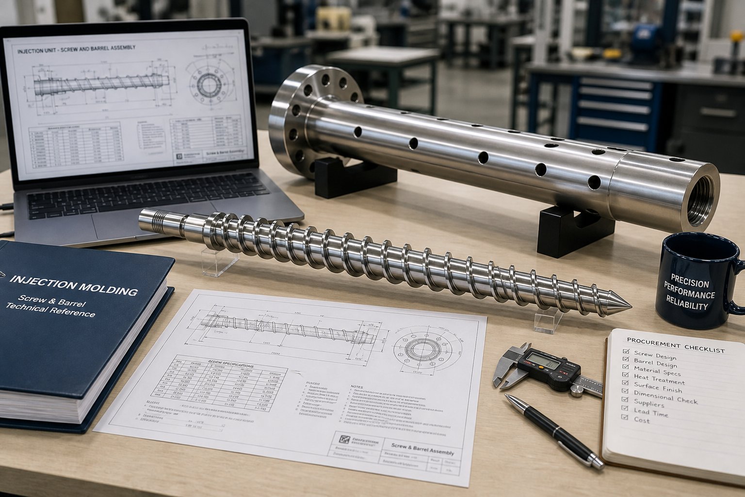
How to Specify and Source the Right Replacement Screw and Barrel
Measurements are on the table. The wear patterns tell a clear story. You know whether the problem is abrasion, corrosion, or both — and whether a rebuild, re-line, or full replacement is the right economic call. The next move is the one that determines whether your new or refurbished plasticizing components deliver years of stable performance or repeat the same premature failure cycle you just diagnosed.
Specifying a replacement screw and barrel is not a catalog exercise. It is an engineering decision that connects resin chemistry, part quality requirements, production economics, current wear evidence, and design optimization into a single, coherent component specification. Skip any one of those inputs and you are gambling — paying premium prices for metallurgy you do not need, or under-specifying components that will wear out before the next scheduled inspection.
Five Questions to Answer Before Specifying Components
Before contacting any feed screw manufacturers or requesting a quote, work through these five decision pillars in order. Each question narrows the specification from broad categories toward the exact screw design, metallurgy, and barrel lining combination your application demands.
- What resins are you processing — and what wear mechanisms do they impose? This is the foundation of every specification decision. Unfilled polyolefins impose mild adhesive wear. Glass-filled nylon delivers severe abrasion. PVC and flame-retardant compounds generate corrosive acid attack. Many real-world applications combine mechanisms — a 20% glass-filled, flame-retardant nylon hits you with abrasion and corrosion simultaneously. Map your resin portfolio to the wear mechanism table from earlier in this article, and you will immediately know which metallurgy families belong on your short list.
- What are your part quality requirements? A shipping crate and a medical device housing both start as plastic pellets, but their tolerance for melt inconsistency could not be more different. Surface finish demands, dimensional tolerances, mechanical property specifications, and cosmetic consistency standards all influence screw geometry selection. Barrier screws and mixing elements deliver tighter melt uniformity than general-purpose designs — but they cost more and require application-specific engineering. Let your reject rate and customer quality expectations drive this decision, not the default option on a quote form.
- What is your production volume and cycle time target? A custom injection molding screw with tungsten carbide hardfacing and a WC-lined bimetallic barrel may cost 2.5 to 3 times more than a standard nitrided set — but if that premium metallurgy lasts four times longer under your operating conditions, the total cost per molded part drops significantly. High-volume, multi-shift operations almost always justify premium metallurgy because the denominator in the cost-per-hour equation is large enough to absorb the higher numerator. Lower-volume shops running easy resins may find that standard metallurgy delivers the best return. Run the math on your actual production schedule, not on an idealized scenario.
- What wear symptoms are you currently experiencing — and do they point to screw wear, barrel wear, or both? Your diagnostic measurements and wear pattern analysis from the inspection process answer this directly. If the barrel bore is within tolerance but the screw flights are worn beyond limits, a screw replacement alone may be justified — provided the barrel still has enough remaining service life to match the new screw's expected lifespan. If both components show significant wear, replacing them as a matched set is the only approach that avoids the mismatch penalty discussed throughout this article. Resist the temptation to save money by replacing only one half of a worn system.
- Do you need a direct OEM replacement, or is this an opportunity to upgrade? Every replacement event is a decision point. You can order the same screw geometry and barrel metallurgy the machine shipped with — or you can use the replacement as an opportunity to upgrade. Maybe your resin mix has shifted toward more abrasive compounds since the original components were specified. Maybe a barrier screw design would eliminate the unmelted particles your GP screw has been struggling with. Maybe your barrel was originally nitrided and your current glass-filled application demands bimetallic protection. Treating a replacement as a specification review — not just a reorder — often delivers more value than the component cost itself.
From Diagnosis to Specification in Practice
Imagine you are a maintenance engineer at a plant running 30% glass-filled nylon 66 on a 150-ton injection press, two shifts per day. Recovery time has increased 15% over the past three months, and your last screw pull showed flight OD wear concentrated in the feed section — classic abrasive damage. The barrel bore measurement shows diametral clearance approaching the "monitor closely" threshold.
Walking through the five pillars in sequence, your specification crystallizes quickly. Pillar one identifies severe abrasive wear as the dominant mechanism. Pillar two confirms that your automotive customer demands tight dimensional tolerances and consistent mechanical properties. Pillar three calculates that the press runs roughly 4,500 hours per year — easily justifying premium metallurgy on a cost-per-hour basis. Pillar four shows both screw and barrel approaching wear limits, pointing toward a matched replacement set. Pillar five reveals that the original GP screw and nitrided barrel were under-specified for the glass-filled nylon application from the start — this is the opportunity to upgrade to a barrier screw with tungsten carbide hardfacing and a WC-lined bimetallic barrel.
That sequence — resin, quality, volume, diagnosis, upgrade opportunity — transforms a reactive purchase order into a specification that addresses the root cause of premature wear rather than simply resetting the clock on the same failure mode.
Choosing a Manufacturing Partner for Replacement Components
The specification is only as good as the manufacturer who executes it. A precisely defined screw geometry and metallurgy combination means nothing if the finished component arrives with bore straightness outside tolerance, inconsistent alloy composition in the bimetallic lining, or flight dimensions that do not match your machine platform. When evaluating feed screw manufacturers for replacement screw and barrel sets, prioritize capabilities over catalog size.
Look for manufacturers who can demonstrate:
- Application engineering support — the ability to discuss your resin, wear patterns, and quality requirements and recommend a specification, not just quote whatever you request
- Custom manufacturing to your machine's dimensional requirements, including non-standard L/D ratios, spline configurations, and screw tip assemblies
- Documented material and hardness specifications with incoming material certification and post-process verification
- Experience serving injection molding factories, machine rebuilders, and maintenance engineering teams — the people who understand that fit, metallurgy, and dimensional precision are non-negotiable
For readers ready to move from diagnosis to action, NANHAIYA's Injection Molding Screw Barrel page connects these specification topics directly to custom screw barrel manufacturing for injection molding machines. NANHAIYA serves the exact audience following this decision framework — injection molding factories, machine rebuilders, and maintenance engineers sourcing precisely manufactured replacement plasticizing components matched to specific machine and application requirements. It is a practical starting point for turning your specification into a component that performs on the production floor.
The thread running through this entire article comes back to one principle: injection molding screws and barrels are an interdependent system, and every decision — from metallurgy selection to inspection intervals to manufacturing partner choice — should reflect that reality. Measure both. Specify both. Replace both. And choose a partner who understands that a screw and barrel matched to your resin, your machine, and your quality standard is not a commodity purchase. It is the foundation of every good part your press will ever produce.
Frequently Asked Questions About Injection Molding Screws and Barrels
1. How often should injection molding screws and barrels be inspected for wear?
Inspection frequency depends on resin abrasiveness and production intensity. For unfilled commodity resins on single-shift operation, a full screw pull and bore measurement every 4,000-6,000 operating hours is sufficient. Moderately filled engineering resins on two-shift schedules warrant inspection every 2,000-4,000 hours. Heavily glass-filled or mineral-filled compounds running 24/7 require inspection every 1,000-2,000 hours. Always base intervals on operating hours or shot counts rather than calendar dates, since machines processing abrasive materials accumulate wear far faster than those running clean polymers.
2. What is the difference between a general-purpose screw and a barrier screw in injection molding?
A general-purpose (GP) screw uses a single-flight, three-zone design that handles a wide range of commodity resins cost-effectively. However, it can struggle with unmelted particles at higher throughputs or with engineering-grade materials. A barrier screw introduces a secondary flight in the transition zone that physically separates the solid bed from the melt pool. This eliminates solid-bed breakup, delivers more uniform melt temperature, and can improve recovery times by 15-20%. Barrier screws are particularly beneficial for semi-crystalline resins like nylon, PET, and HDPE that have narrow processing windows.
3. When should I choose a bimetallic barrel over a nitrided barrel?
Nitrided barrels provide a hard case layer only 0.4-0.6 mm deep and work well for unfilled commodity resins at moderate production volumes. Once you process glass-filled, mineral-filled, or corrosive resins like PVC and flame-retardant compounds, the thin nitrided case wears through rapidly — sometimes in as little as 6-12 months. Bimetallic barrels feature a centrifugally cast alloy lining 1.5-3.0 mm thick, offering three to six times the effective wear depth. Choose tungsten carbide bimetallic linings for abrasive fillers and nickel-based linings for chemically aggressive resins. Though upfront costs are 2-3x higher, total cost per operating hour is often significantly lower.
4. Can injection molding screws and extrusion screws be used interchangeably?
No, they cannot be swapped even when diameters match. Injection screws reciprocate axially and must interface with a non-return valve to control shot size during injection — extrusion screws have no such provision. Injection screws also use shorter L/D ratios (18:1-24:1 vs. 24:1-36:1), lower compression ratios, and are engineered to withstand cyclic axial thrust forces that extrusion screws never experience. Barrel specifications differ as well, including length, feed throat design, venting provisions, and pressure ratings. Installing the wrong screw type risks damaged components, uncontrolled shot sizes, and significant scrap.
5. Should I rebuild or replace a worn injection molding screw and barrel?
The decision depends on remaining base material condition, prior rebuild history, and application requirements. Rebuilding — re-hardfacing flights and honing the barrel bore — costs 40-60% of new components and restores 70-95% of original performance when the base metal is sound. However, a screw should not be refurbished more than three times, as repeated welding degrades the substrate. Full replacement is the right call when base material shows cracking, deep pitting, excessive bowing, or when upgrading geometry or metallurgy for a new application. Manufacturers like NANHAIYA (nhyscrews.com) offer custom screw and barrel manufacturing matched to specific machine and resin requirements for processors ready to source precision replacements.
Written by
Nanhaiya Technical Team
Zhoushan Nanhaiya Plastic Machinery Co., Ltd.
The Nanhaiya technical team supports screw and barrel manufacturing projects through application review, technical communication, custom manufacturing coordination, and production and quality control.
Discuss Your Application
Related Articles
More insights on screw barrel technology and plastics processing.

What Nobody Tells You About Screw Barrel For Plastic Machine Design
Oct 10, 2026
Learn how screw barrel for plastic machine design affects melt quality, throughput, and wear life. Covers geometry, resin matching, troubleshooting, and sourcing.
Read Article
Single Screw Extruder for Sheet: Stop Guessing, Start Specifying
Oct 9, 2026
Learn how to specify a single screw extruder for sheet production. Covers screw geometry, resin-specific processing, troubleshooting, and maintenance best practices.
Read Article
PE Pipe Extruder Machine: What Datasheets Won't Tell You
Oct 9, 2026
Learn how a PE pipe extruder machine works, key specs explained, material grade selection, maintenance tips, and buyer guidance beyond the datasheet.
Read ArticleLooking for something else?
Search by material, symptom or product and jump straight to the relevant page.
These are navigation suggestions based on keyword matching — not a quotation, not a delivery commitment, and not a substitute for engineering review. Final specification is confirmed by our engineers against your drawings and processed material.
Need help with screw barrel selection?
Share your machine model, processed material and application. Our team can help with pricing and technical support.