

What Injection Molding Screws Do and Why They Matter
Imagine a single component inside your molding machine that touches every pellet of resin, controls how uniformly that resin melts, and ultimately determines whether the finished part meets spec or ends up in the scrap bin. That component is the plasticating screw, and it is doing far more work than most operators give it credit for.
Defining the Injection Molding Screw
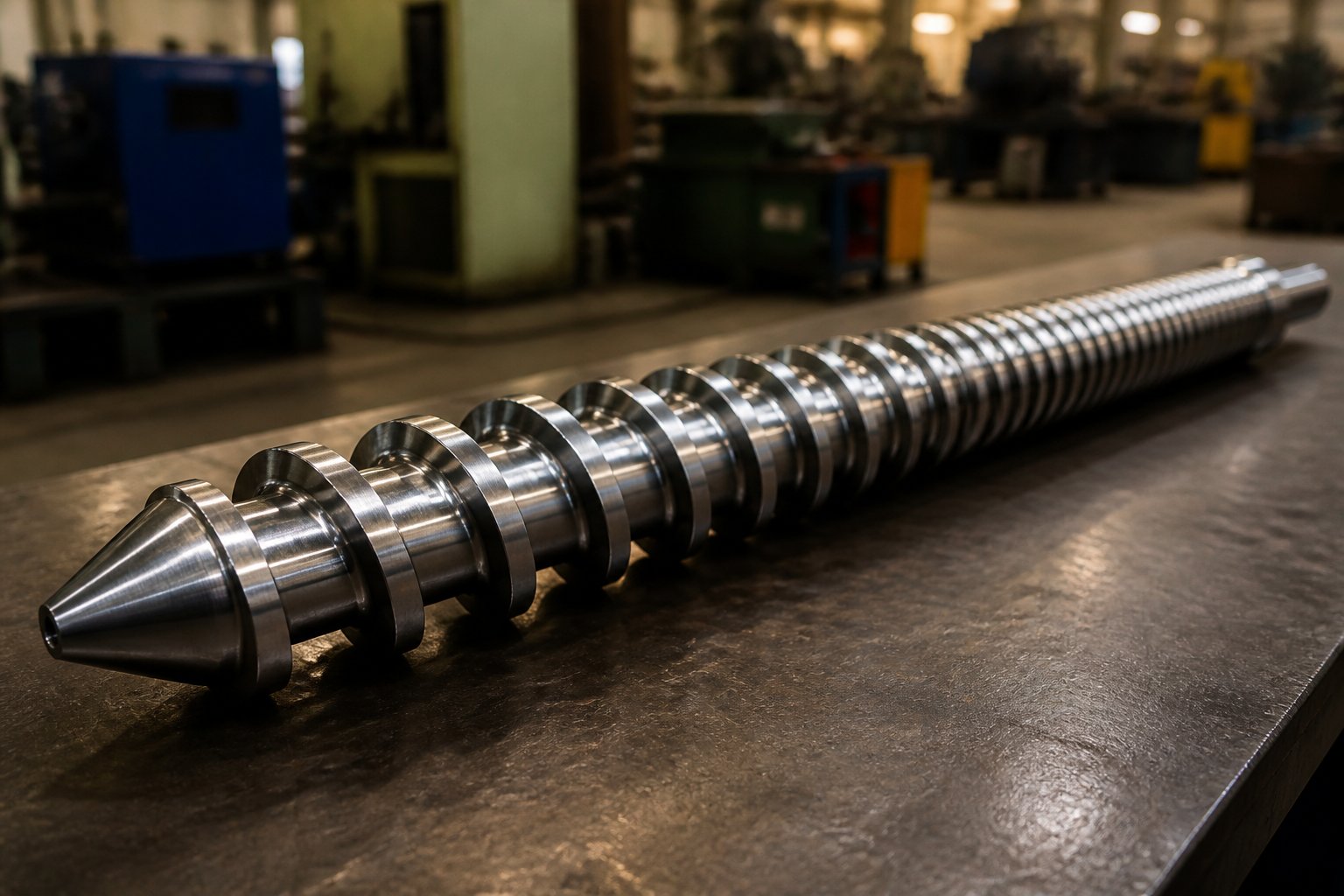
An injection molding screw is a helical, rotating shaft housed inside a heated barrel that conveys, compresses, melts, and meters polymer resin into a mold cavity. It serves as the primary plasticating component in every injection molding machine, directly governing melt quality, shot consistency, and cycle efficiency.
So what does an injection molding screw do in practical terms? Picture solid plastic pellets dropping from a hopper into the barrel. The screw's rotating flights grab those pellets, push them forward, and gradually compress them against the heated barrel wall. Friction and conducted heat work together to transform rigid granules into a homogeneous molten stream. By the time the melt reaches the front of the barrel, the screw has also metered it to a precise volume and pressure, ready for injection into the mold. Every phase of this journey — solids conveying, compression, shear-induced melting, and final homogenization — happens along different sections of the same screw, making its geometry one of the most consequential design choices in the entire process.
Why Screw Performance Drives Part Quality and Profitability
The plasticating screw's role in injection molding goes well beyond simply melting plastic. Its design and condition ripple outward into nearly every production metric you track. A well-matched screw delivers uniform melt temperature, stable shot weights, and repeatable fill patterns — the foundations of consistent part quality. A worn or poorly selected one introduces variability that shows up as short shots, burn marks, splay, or dimensional drift.
The financial stakes are significant. Quality-management research from ASQ consistently shows that many manufacturers lose 10-15% of operating costs to poor quality, including scrap, rework, and warranty claims. In injection molding, the screw is often the root cause hiding behind those losses. Excessive flight wear increases melt leakage and energy consumption. The wrong compression ratio for a given resin can spike cycle times or degrade the polymer. Even subtle geometry mismatches silently erode throughput over thousands of cycles.
Understanding how injection molding screws affect part quality is therefore not optional knowledge — it is the difference between a process that runs predictably and one that fights you every shift. This guide serves as a unified reference covering screw anatomy and functional zones, the full range of screw types and when each design excels, critical parameters like L/D ratio and compression ratio, metallurgy and wear-resistance options, resin-specific selection guidance, defect troubleshooting tied to screw condition, and a practical maintenance and replacement framework. Each of these topics builds on the last, starting with the three functional zones that define every plasticating screw's behavior.
Anatomy of an Injection Molding Screw and Its Three Functional Zones
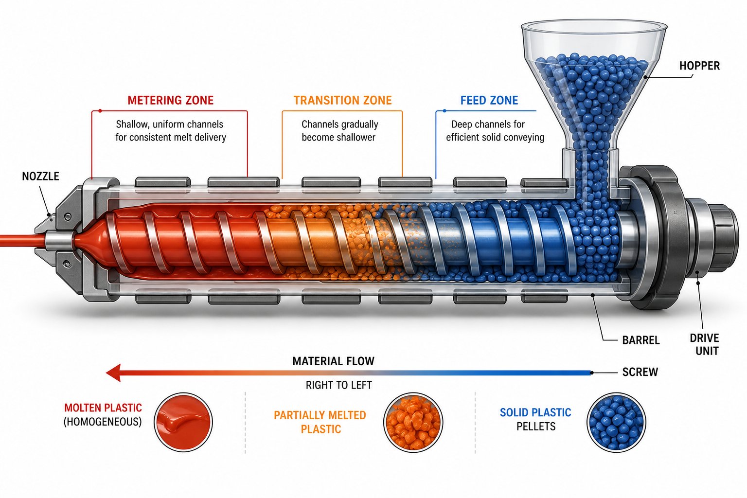
Every injection molding screw looks like a single continuous helix, yet the work it performs changes dramatically from one end to the other. The screw is divided into three distinct functional zones — feed, transition (compression), and metering — each engineered to handle a specific stage of the plasticating process. How channel depth shifts across these zones, and how much of the screw's total length each zone occupies, directly shapes melt quality for every resin you run. Understanding these injection molding screw zones is the first step toward diagnosing performance issues and selecting the right geometry for a given application.
Feed Zone – Solids Conveying and Intake
The feed zone is the rearmost section of the screw, sitting directly beneath the hopper throat where solid pellets first enter the barrel. Its primary job is deceptively simple: grab the granules and push them forward. But consistent solids conveying is harder than it sounds, because it depends on friction between the pellets, the barrel wall, and the screw root surface.
- Deepest channel depth — The flights in this zone have the greatest radial distance between the screw root and flight tip, creating a large channel volume to accept bulk material at its lowest density.
- Constant channel depth — Unlike downstream zones, the feed section maintains a uniform depth along its entire length, providing steady transport without premature compression.
- Typical length proportion — On a standard general-purpose screw, the feed zone often occupies roughly 50% of the total flighted length, though this varies by design intent.
- Air evacuation — As pellets compact against one another, trapped air is pushed rearward through the hopper throat, essentially using the feed zone as a vent.
- Preheating through friction — Pellet-to-barrel and pellet-to-pellet friction begins transferring energy into the resin, but no significant melting should occur here. Premature melting — sometimes called "bridging" — blocks material flow and starves downstream zones.
Think of the feed zone as the conveyor belt of the screw. If it cannot deliver a consistent, well-compacted plug of solid material, every zone that follows will underperform regardless of its own design.
Transition Zone – Compression and Melting
The transition zone, also called the compression zone, is where the real transformation happens. Here, the screw root diameter gradually increases, reducing the channel depth and compressing the material against the heated barrel wall. This compression, combined with frictional shear, drives the bulk of the energy needed to melt the polymer — roughly 60-80% of total heat input comes from mechanical shear rather than the barrel's external heater bands.
- Progressively decreasing channel depth — The taper from deep feed-zone channels to shallow metering-zone channels forces material into tighter contact with the barrel, intensifying heat transfer and shear.
- Primary melting region — Solid pellets pressed against the hot barrel wall form a thin melt film that is scraped forward by the advancing flight, gradually consuming the solid bed.
- Air and volatile expulsion — Compression squeezes out remaining air pockets and low-level volatiles, reducing the risk of voids or splay in molded parts.
- Compression ratio origin — The ratio of feed-zone channel depth to metering-zone channel depth defines the screw's compression ratio. A typical general-purpose screw falls in the 2.5:1 to 3.0:1 range.
The compression ratio is not just a feeding metric. As industry expert analysis emphasizes, it also governs the shear rates throughout the screw, determining how much mechanical energy per unit of output goes into the polymer to complete melting. Every resin has a different energy requirement, so the compression ratio must account for viscosity behavior, specific heat, and the target exit temperature.
Here is where the injection screw compression zone function becomes especially critical for resin selection. Semi-crystalline materials like nylon and polyethylene stay hard until they reach their melting point — much like ice, they do not gradually soften but instead require a distinct energy threshold (heat of fusion) to break their ordered chain structure. This behavior can cause "solid-bed breakup," where unmelted fragments survive the transition zone and end up in the part. Semi-crystalline resins therefore often benefit from a shorter, more aggressive compression zone that delivers concentrated energy quickly.
Amorphous resins like ABS and polycarbonate behave differently. They soften progressively as temperature rises, more like frozen butter warming on a counter. Because there is no sharp melt point and no heat of fusion to overcome, they are more forgiving during plasticating and generally perform best with a longer, more gradual transition zone that avoids excessive shear heating.
Metering Zone – Homogenization and Delivery
By the time material reaches the metering zone, the screw's final section, it should be fully molten. The metering zone's job is to homogenize the melt — evening out temperature gradients, pressure variations, and any remaining compositional inconsistencies — and then deliver it at a stable, controlled rate to the front of the barrel for injection.
- Shallowest and constant channel depth — The shallow, uniform channel applies consistent shear across the melt, promoting temperature and viscosity uniformity.
- Pressure generation — The metering zone builds the head pressure needed to push the melt through the non-return valve (check ring) and ultimately into the mold.
- Flow-rate stabilization — A properly designed metering section dampens the pulsation effects from screw rotation, producing a steady plasticating rate shot after shot.
- Typical length proportion — The metering zone commonly occupies 20-30% of the screw's flighted length, though high-performance designs may extend this region for improved homogeneity.
You'll notice that how channel depth affects screw performance ties every zone together in a single geometric story. The deep feed channel accepts bulky pellets, the tapering transition channel converts them to melt through compression and shear, and the shallow metering channel polishes that melt into a uniform, pressure-stable stream. Altering the relative length of any one zone — making the transition shorter and steeper, or extending the metering section — shifts the balance of energy input, residence time, and mixing intensity across the entire screw.
This zone-ratio interplay is exactly why a single screw geometry cannot serve all resins equally well. Matching the feed, transition, and metering proportions to the thermal and rheological behavior of your specific resin family is the foundation of optimized plasticating — and that leads directly to the question of which screw type best suits a given application.
Types of Injection Molding Screws and When to Use Each Design
Choosing between screw designs is one of those decisions that quietly shapes everything downstream — cycle time, melt consistency, defect rates, and even component longevity. Yet many processors default to whatever screw shipped with the machine, never questioning whether a different type would solve persistent quality problems. The reality is that several distinct screw architectures exist, each engineered to excel under specific conditions. Knowing the full range of types of injection molding screws — and understanding when each design earns its place — is the fastest way to close the gap between the parts you are getting and the parts you actually need.
General-Purpose vs. Barrier Screws
The general-purpose (GP) screw is the workhorse of the industry, and for good reason. Its straightforward three-zone layout — feed, transition, metering — handles a wide variety of commodity resins like polyethylene, polypropylene, and polystyrene without requiring specialized geometry. Most GP designs use a roughly equal 1:1:1 zone-length ratio and a moderate compression ratio in the 2.5:1 to 3.0:1 range. If you are running multiple material families on a single machine with frequent changeovers, a GP screw gives you the flexibility to stay productive without swapping hardware every shift.
Its limitation, however, becomes obvious when production speeds climb or when you switch to semi-crystalline engineering resins with sharp melt points. A single-flight design has a finite melting capacity. Push it past that ceiling and you will find unmelted particles — sometimes called "unmelts" or "fisheyes" — embedded in finished parts. No amount of temperature adjustment or back-pressure tweaking can compensate for a fundamental melting-capacity shortfall.
This is precisely the problem barrier screws were designed to solve. A barrier screw introduces a secondary flight — often called a barrier flight — within the transition zone, creating two separate channels: one for solid material and one for melt. As polymer melts against the barrel wall, it flows over the barrier flight into the melt channel, while unmelted pellets remain trapped in the solids channel until they fully liquefy. The result? Peer-reviewed analysis confirms that this dual-channel architecture promotes and stabilizes polymer melting, virtually eliminating unmelts from reaching the metering zone. The Maillefer design is one of the most recognized barrier configurations, though several proprietary variations exist across manufacturers.
When weighing a barrier screw vs general purpose screw, the decision comes down to application demands. If melting capacity is your bottleneck — high-output runs, semi-crystalline resins like nylon or PBT, or tight tolerance parts where a single unmelted speck means rejection — a barrier screw justifies its higher cost. For shops running moderate volumes of forgiving commodity resins, the GP screw remains the smarter, more economical default.
Mixing, Vented, and Specialty Screw Designs
Beyond the GP-versus-barrier choice, several other screw architectures target specific processing challenges that neither baseline design fully addresses.
Mixing screws with dispersive elements tackle the problem of color and additive uniformity. A Maddock (also called LeRoy or fluted) mixer is the most common dispersive design. It forces the melt through a narrow gap between alternating inflow and outflow flutes, applying intense shear that breaks apart pigment agglomerates and gel particles. This mixing screw design for color masterbatch work is often the difference between acceptable color consistency and parts with visible streaks. However, that same high shear can overheat sensitive polymers, so material selection matters.
Distributive-mixing pin screws take the opposite approach. Rows of pins protruding from the screw root repeatedly split and recombine the melt stream, spreading additives evenly without aggressive shear. Think of them as gentle stirrers rather than high-energy blenders. Pin mixers are the better choice for shear-sensitive materials like TPU, certain TPEs, and some bioplastics where a Maddock section would risk thermal degradation. Industry publications note that distributive mixers pair especially well with barrier screws, since the barrier section already handles melting and adding further high-shear elements would risk overdoing it.
Vented (two-stage) screws solve a completely different problem: moisture and volatile removal during plasticating. Hygroscopic resins such as polycarbonate, nylon, and ABS absorb atmospheric moisture that turns to steam during processing, causing silver streaks, splay, and structural weakness. A vented screw for injection molding is essentially two screw stages connected in series. The first stage melts the resin normally. Then a decompression zone — where channel depth increases sharply — drops internal pressure, allowing a barrel vent port to exhaust moisture and volatiles. The second stage re-compresses and meters the degassed melt. In some operations, this two-stage approach can reduce or even eliminate the need for standalone drying equipment, though precise decompression-zone design is critical to prevent molten polymer from flowing out the vent.
Specialty screws round out the taxonomy for niche but growing application areas. Micro-molding screws — sometimes as small as 12-14 mm in diameter — are designed for extremely small shot sizes where standard screw volumes would cause excessive residence time and degradation. Liquid silicone rubber (LSR) screws feature unique geometries and check-valve arrangements optimized for the low viscosity and rapid cure behavior of thermoset silicones. And as sustainability drives adoption of PLA and PHA bioplastics, screws with lower compression ratios and gentler transition profiles are emerging to accommodate these materials' narrower processing windows and distinct melt rheology.
Screw Type Selection Matrix
Understanding how to choose injection molding screw type becomes much easier with a side-by-side comparison. The following matrix maps each design to its defining feature, best-fit application, and the primary advantage it delivers.
| Screw Type | Key Design Feature | Ideal Resin or Application | Primary Advantage |
|---|---|---|---|
| General-Purpose (GP) | Single-flight, three-zone layout with equal zone proportions | Commodity resins (PE, PP, PS); frequent material changeovers | Versatility and low cost across a broad range of materials |
| Barrier (e.g., Maillefer) | Secondary barrier flight creating separate solids and melt channels | Semi-crystalline engineering resins (PA, PBT, POM); high-output runs | Eliminates unmelted particles and stabilizes output consistency |
| Dispersive Mixing (Maddock/LeRoy) | Fluted mixing section with shear dams at screw tip | Color masterbatch, pigmented resins, filled compounds requiring agglomerate breakup | Superior color dispersion and additive uniformity |
| Distributive Mixing (Pin/Pineapple) | Pins or slotted geometry that split and recombine melt streams | Shear-sensitive resins (TPU, TPE, bioplastics); gentle blending tasks | Even distribution of additives without excessive shear heating |
| Vented / Two-Stage | Decompression zone with barrel vent port between two plasticating stages | Hygroscopic resins (PC, PA, ABS); recyclate with residual moisture | Degasses moisture and volatiles in-process, reducing drying requirements |
| Micro-Molding | Ultra-small diameter (12-14 mm) with minimized shot volume | Medical devices, micro-electronics, precision micro-parts | Prevents degradation from excessive residence time in tiny shot sizes |
| LSR (Liquid Silicone Rubber) | Specialized geometry and check-valve system for low-viscosity thermosets | Liquid silicone rubber components, overmolded seals, medical silicone parts | Handles rapid cure and low viscosity without premature crosslinking |
| Bioplastic-Optimized | Lower compression ratio with extended, gentle transition zone | PLA, PHA, and other biodegradable polymers with narrow processing windows | Accommodates thermal sensitivity and unique melt behavior of bio-based resins |
No single screw type is universally superior — each earns its advantage within a specific operational context. The real risk is defaulting to a general-purpose design out of habit when the application genuinely demands barrier melting, dedicated mixing, or degassing capability. Persistent quality problems that resist process adjustments are often a signal that the screw type itself is the limiting factor, not the temperature profile or back-pressure setting.
Selecting the right screw architecture, however, is only half the equation. The screw's physical dimensions — its L/D ratio, compression ratio, and flight geometry — determine how effectively any given design performs its intended function, and those parameters deserve their own focused analysis.
Critical Design Parameters Every Injection Molding Engineer Should Know
You can pick the perfect screw type for your application, yet still end up fighting inconsistent melt if the screw's dimensional parameters are wrong. Think of screw architecture as the blueprint and design parameters as the measurements that bring that blueprint to life. Two barrier screws with identical layouts but different L/D ratios, compression ratios, or flight geometries will produce noticeably different melt quality on the same resin. These numbers are not abstract specifications buried in a datasheet — they are the levers that control how much energy enters the polymer, how long the resin stays inside the barrel, and how uniform the melt stream is when it reaches the mold.
Despite their importance, many resources mention these parameters without explaining how to calculate them or what ranges are appropriate for different processing scenarios. The sections below break each one down in practical terms so you can evaluate whether your current screw geometry is helping or hurting your process.
Understanding L/D Ratio and Standard Ranges
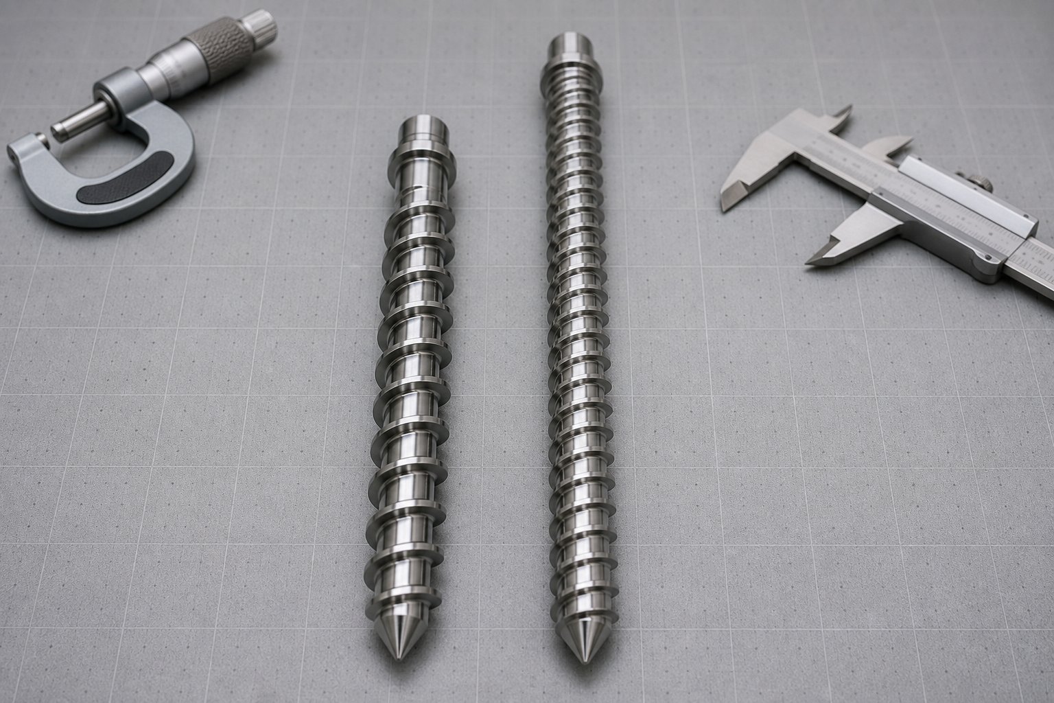
The L/D ratio — length-to-diameter ratio — is the most frequently cited specification for any plasticating screw, yet it is also one of the most misunderstood. The calculation itself is straightforward: divide the screw's flighted length (the portion with helical flights, not the total shaft length) by its nominal outer diameter. A screw with 500 mm of flighted length and a 25 mm diameter has an L/D ratio of 20:1.
Why does this number matter? A higher L/D ratio means the resin spends more time traveling along the screw, receiving additional shear work and barrel heat before reaching the front of the barrel. This extended residence increases energy input and improves melt homogeneity — beneficial for resins that need thorough melting or for applications demanding extremely uniform melt temperature.
Standard injection molding screws typically fall in the 20:1 to 24:1 range. As injection molding machine manufacturers note, a 20:1 ratio remains the most common baseline, while options extending into the 24:1 to 30:1 range are increasingly offered for specific resin families like PE and PP. High-performance or specialty screws — particularly those designed for engineering polymers, color-critical applications, or barrier designs — may reach 26:1 or higher to squeeze more mixing and homogenization out of each revolution.
More length is not automatically better, though. Excessively long screws increase residence time beyond what thermally stable polymers require, potentially driving up melt temperatures to the point of degradation. This shows up as color shifts, loss of additive effectiveness, or even polymer decomposition. Engineering polymers with tight thermal windows are especially vulnerable. A longer screw also concentrates more shear work on the melt, and for shear-sensitive resins, that extra energy does more harm than good.
The practical takeaway? Match the L/D ratio to the resin's thermal stability and the application's quality demands. Commodity polyolefins tolerate and often benefit from ratios in the 22:1 to 26:1 range. Shear-sensitive or thermally fragile resins typically perform better at 20:1 to 22:1, where residence time stays short enough to avoid degradation.
How Compression Ratio Affects Melt Quality
If the L/D ratio governs how long the polymer interacts with the screw, the compression ratio governs how aggressively it is worked during that journey. Here is how to calculate screw compression ratio: divide the channel depth in the feed zone by the channel depth in the metering zone. A screw with a 6.0 mm feed-zone depth and a 2.0 mm metering-zone depth has a compression ratio of 3.0:1.
This ratio directly controls how much volume reduction — and therefore shear energy — the resin experiences as it moves from the deep feed channel into the shallow metering channel. A higher compression ratio packs the material more tightly, increases shear heating, and accelerates melting. A lower ratio reduces shear intensity, preserving molecular structure in heat-sensitive polymers but potentially leaving melt less thoroughly homogenized.
General-purpose screws typically land in the 2.5:1 to 3.0:1 range, a middle ground that works acceptably across many commodity resins. Semi-crystalline materials with sharp melting points — nylon, POM, PBT — often require ratios at the higher end (2.8:1 to 3.5:1) because their crystalline structures demand concentrated energy to break down. Amorphous resins like polycarbonate and PMMA, which soften gradually, generally favor the lower end (1.8:1 to 2.5:1) to avoid overheating and degradation.
Heat-sensitive resins push this principle even further. PVC, for instance, has a notoriously narrow gap between its processing temperature and its degradation temperature. Screws designed for PVC often use compression ratios as low as 1.5:1 to 2.0:1, relying more on barrel heat and extended residence time than on mechanical shear to achieve melting. The same philosophy applies to certain bioplastics and medical-grade polymers where molecular integrity is non-negotiable.
Injection Screw Flight Geometry Parameters
Beyond L/D and compression ratio, a set of secondary geometry parameters fine-tunes how the screw conveys, shears, and pressurizes the melt. These are less frequently discussed but have a real impact on day-to-day processing:
- Flight width (land width) — The flat top surface of each flight that rides against the barrel bore. Wider flights increase the sealing effect between screw turns, reducing melt leakback over the flight tip. However, excessive flight width also increases shear on the thin melt film between flight and barrel, which can overheat sensitive resins. A standard flight width is approximately 10% of the screw diameter.
- Helix angle — The angle at which the flight spirals along the screw root. Most injection screws use a helix angle of approximately 17.66 degrees (equivalent to a pitch equal to the screw diameter — one full flight turn per diameter of axial length). Steeper angles increase the forward conveying component, while shallower angles increase the residence time and shear exposure per turn.
- Channel depth — Already discussed as the driver of compression ratio, channel depth also determines the volume of material processed per screw revolution. Deeper metering channels allow higher throughput but reduce shear intensity, while shallower channels intensify mixing at the cost of output volume. This trade-off is central to optimizing for specific part sizes and cycle times.
These parameters interact with one another. Changing flight width without adjusting channel depth, for example, alters the ratio of shear area to channel volume. Experienced screw designers balance all three geometry factors against the target resin and production requirements, which is why off-the-shelf screws sometimes underperform compared to purpose-engineered designs.
Effective Plasticating Rate – RPM, Back Pressure, and Geometry
Here is a concept that often gets overlooked entirely: the effective plasticating rate. This is the actual throughput of fully homogenized, ready-to-inject melt that a screw delivers per unit of time, and it depends on the interaction between screw RPM, back pressure, and the geometry parameters discussed above.
Screw RPM is the most visible variable. Higher rotational speed moves more resin through the barrel faster, generating more shear heat in the process. But there is a ceiling. As processing guides emphasize, polymer manufacturers specify limiting screw speeds — often expressed as a maximum peripheral velocity of 0.05 to 0.3 m/s around the screw's circumference — beyond which shear damage degrades the resin. Exceeding these limits may appear to increase throughput on paper while actually raising scrap rates and reducing part performance.
Back pressure is the hydraulic resistance applied behind the screw during recovery. As Plastics Technology details, it serves three critical functions: it controls the screw's return speed for consistent shot-size positioning, it compresses the melt to expel volatiles and trapped air from the transition zone, and it increases melt density for repeatable shot weights. Too little back pressure produces inconsistent melt density and shot-weight variation. Too much extends recovery time, overheats the melt, and can accelerate screw and barrel wear.
Geometry ties these variables together. A screw with a higher compression ratio generates more internal pressure at a given RPM, meaning it may need less back pressure to achieve the same melt density. A longer L/D ratio allows higher screw speeds without sacrificing residence time — but only for thermally stable polymers. A screw with worn flight tips loses its sealing efficiency, so melt leaks backward over the flights, reducing the effective forward output regardless of how fast you spin the screw or how much back pressure you apply.
The practical lesson? Effective plasticating rate is not a single setting — it is the combined result of geometry, process parameters, and component condition. Optimizing it means finding the RPM and back-pressure combination that maximizes homogeneous melt output for your specific screw geometry and resin, without crossing into degradation territory. When a process that once ran smoothly starts requiring higher RPM or more back pressure to maintain the same quality, it is often the earliest signal that screw or barrel wear has begun eroding the effective plasticating rate.
Design Parameter Comparison Across Screw Types
The following table consolidates standard parameter ranges for the most common screw architectures, giving you a quick reference to compare your current setup against recommended values.
| Parameter | General-Purpose (GP) Screw | Barrier Screw | Mixing Screw (with Maddock/Pin Section) |
|---|---|---|---|
| Typical L/D Ratio | 20:1 to 24:1 | 22:1 to 26:1 | 22:1 to 26:1 |
| Compression Ratio | 2.5:1 to 3.0:1 | 2.0:1 to 2.8:1 (barrier flight manages compression) | 2.5:1 to 3.0:1 (mixing section adds homogenization) |
| Feed Zone Length (% of flighted length) | ~50% | ~40-50% (solids channel starts early) | ~45-50% |
| Transition Zone Length | ~25% | ~30-35% (extended barrier section) | ~20-25% (mixing section replaces some transition length) |
| Metering Zone Length | ~25% | ~20-25% | ~20% + dedicated mixer length |
| Typical Helix Angle | ~17.66 degrees (square pitch) | ~17.66 degrees (primary flight) | ~17.66 degrees (primary flight) |
| Flight Width | ~0.10 x diameter | Primary: ~0.10 x dia; Barrier: narrower | ~0.10 x diameter (mixer geometry varies) |
| Best Suited For | Multi-resin flexibility, commodity polymers | Semi-crystalline resins, high-output consistency | Color-critical work, filled compounds, additive-heavy formulations |
Notice how barrier screws often use a lower compression ratio than GP designs. This might seem counterintuitive, since barrier screws are intended for harder-to-melt semi-crystalline resins. The reason is that the barrier flight itself manages the melting process so efficiently — separating solids from melt mechanically — that the screw does not need to rely as heavily on compression-driven shear. The geometry does the work that brute-force compression would otherwise handle.
These parameters define how a screw converts pellets into melt. But even the best geometry cannot perform indefinitely if the screw's material cannot withstand the abrasion, corrosion, and thermal loads of continuous production — which makes metallurgy and surface treatment the natural next consideration.
Screw and Barrel Materials That Resist Wear and Corrosion
A perfectly designed screw geometry means little if the metal it is made from cannot survive the environment inside the barrel. Every rotation exposes flight tips to abrasive pellets, corrosive melt gases, and metal-to-metal contact pressures that gradually erode the very dimensions your process depends on. As Plastics Technology notes, wear begins the moment the screw starts turning — and once flight clearances open up, melting efficiency declines, melt leaks backward over the flights, and the process adjustments required to compensate quietly consume energy, cycle time, and part quality. Injection molding screw material selection is therefore not a secondary purchasing decision. It is one of the most consequential choices a processor can make.
Matching screw and barrel metallurgy to the abrasiveness and corrosiveness of the resin being processed is one of the highest-ROI decisions in plasticating component selection — often returning its cost many times over through extended service life, reduced scrap, and lower energy consumption.
Base Steel Grades and Nitriding Treatments
Most screws start life as a machined piece of alloy steel, and the two workhorses of the industry are AISI 4140 and 4150 chromium-molybdenum steels. These grades offer a solid combination of toughness, machinability, and moderate hardness — exactly what you need for a component subjected to cyclic torsional loads and high compressive forces. For processing unfilled commodity resins like polyethylene and polypropylene, a standard 4140 or 4150 screw performs reliably and represents the lowest upfront cost.
To extend the useful life of these base steels, gas nitriding is the most common surface treatment. During nitriding, the screw is exposed to nitrogen-rich gas at elevated temperatures, diffusing nitrogen atoms into the steel surface to form a hard case layer. This process typically achieves surface hardness in the range of 65-70 HRC (Rockwell C) to a depth of roughly 0.2-0.4 mm, providing meaningful resistance to abrasive wear without altering the screw's core toughness.
Think of nitriding as the baseline armor for any plasticating screw. It handles the everyday abrasion from unfilled polymers and low-percentage regrind effectively. However, nitrided screw wear resistance in injection molding has its limits. Run a nitrided 4140 screw on 30% glass-filled nylon, and you will see measurable flight-tip erosion within weeks rather than months. The hard case is simply too thin and not hard enough to resist the cutting action of glass fibers under sustained pressure. That is where advanced materials and coatings earn their place.
Bimetallic and Advanced Alloy Options
When standard nitriding cannot keep pace with wear, processors have several tiers of upgraded protection to consider — each trading higher upfront cost for significantly longer component life.
Bimetallic barrel linings are the industry standard for abrasion-intensive applications. As Santa Fe Machine Works explains, a bimetallic barrel is created by centrifugally casting a wear-resistant alloy lining — typically 1-2 mm thick — onto the inner surface of a pre-machined steel tube. The result is a metallurgical bond between the tough outer shell and a hard, abrasion-resistant bore surface. A bimetallic barrel for glass filled resin processing is not optional — it is essential. Lining alloys are formulated for specific threats: iron/boron-based alloys for general-purpose abrasion resistance, nickel-based alloys with tungsten carbide particles for glass-fiber loadings up to 50%, and nickel-based alloys with zero iron content for severe corrosion resistance against PVC and fluoropolymers.
Hard-faced flight tips complement bimetallic barrels on the screw side. Welding a wear-resistant alloy — such as Colmonoy 56 or stellite-based materials — onto the flight lands creates a hard, abrasion-resistant running surface where the screw contacts the barrel bore. As industry experts caution, it is critical to choose hardfacing alloys that are compatible with the barrel lining material. Alloys with lower tungsten carbide content may be easier to apply, but they wear faster and have a greater tendency to gall when paired with the hardest barrel linings.
Tool steels like D2 and H13 offer higher baseline hardness and heat resistance compared to 4140/4150, making them suitable for screws processing moderately abrasive or high-temperature resins. H13 in particular — a hot-work tool steel with Rockwell hardness around 48-52 HRC — provides good thermal stability and wear resistance for engineering polymers.
Powder metallurgy (PM) steels represent the top tier of screw metallurgy for extreme-wear environments. CPM grades such as CPM 9V and CPM 10V are manufactured through a particle metallurgy process that produces an extremely uniform carbide distribution throughout the steel, delivering exceptional abrasion resistance. RJG Inc. recommends CPM 9V or similar steels for aggressive materials like 33% glass-filled nylon, where standard steel selections would erode rapidly. These steels come at a premium, but for high-volume production of heavily filled compounds, the extended service life often makes them the most economical choice over the component's full lifecycle.
For processors seeking the best screw material for PVC processing, corrosion resistance takes priority over abrasion resistance. PVC releases hydrochloric acid during thermal decomposition, which aggressively attacks iron-based metallurgies. Nickel-based alloys with minimal iron content — both for barrel linings and screw surface treatments — are the proven solution. Some processors running PVC or fluoropolymers also opt for chrome-plated screws, which add a corrosion-resistant barrier, though chrome plating alone does not provide meaningful abrasion protection.
Material Selection Comparison by Application
Choosing the right material or coating depends on balancing three factors: the type of wear your resin inflicts, the production volume driving your cost-per-hour calculation, and the consequences of unplanned downtime. The table below maps each major material and coating option against these considerations.
| Material / Coating Type | Typical Hardness Range | Best-Suited Resin Category | Relative Cost Tier | Expected Service Life Characteristics |
|---|---|---|---|---|
| Nitrided 4140/4150 Steel | 65-70 HRC (surface case) | Unfilled commodity resins (PE, PP, PS) | Low ($$) | Good for non-abrasive applications; shortest life with filled or corrosive resins |
| Hard-Faced Flight Tips (Colmonoy/Stellite) | 55-62 HRC | Moderately filled resins, general engineering polymers | Low-Medium ($$$) | Extends flight-tip life 2-3x vs. nitrided steel; must be compatible with barrel lining |
| Tool Steel (D2, H13) | 48-62 HRC (through-hardened) | Engineering resins, moderately abrasive compounds | Medium ($$$) | Higher heat resistance and baseline hardness than 4140; good for sustained high-temperature processing |
| Bimetallic Barrel Lining (Iron/Boron) | 58-65 HRC | General-purpose abrasion protection; unfilled to lightly filled resins | Medium ($$$) | Significant improvement over unlined barrels; industry baseline for lined applications |
| Bimetallic Barrel Lining (Nickel/Tungsten Carbide) | 60-70 HRC | Glass-filled and mineral-filled compounds (up to 50% loading) | Medium-High ($$$$) | 2-5x longer bore life vs. iron/boron linings in highly abrasive applications |
| Bimetallic Barrel Lining (Nickel-Base, Low/No Iron) | 55-62 HRC | Corrosive resins: PVC, fluoropolymers, halogen-free flame-retardant compounds | Medium-High ($$$$) | Resists chemical attack that destroys iron-based alloys; essential for PVC longevity |
| CPM Powder Metallurgy Steel (9V, 10V) | 58-62 HRC (through-hardened) | Heavily glass-filled engineering resins (30%+ GF nylon, PBT); extreme abrasion environments | High ($$$$$) | Longest service life in highly abrasive applications; uniform carbide structure resists erosion throughout cross-section |
| Chrome Plating (screw surface) | 68-72 HRC (thin surface layer) | PVC, corrosive resins where abrasion is secondary concern | Low-Medium ($$$) | Excellent corrosion barrier; limited abrasion protection due to thin coating layer |
A few patterns emerge from this comparison. First, cost and service life scale together — cheaper metallurgies wear faster under demanding conditions, but they are perfectly adequate for undemanding ones. Spending top dollar on a CPM 9V screw to run unfilled polypropylene is wasteful. Running a nitrided 4140 screw on glass-filled nylon is equally wasteful, just in the opposite direction — through premature wear, downtime, and scrap rather than upfront expense.
Second, abrasion resistance and corrosion resistance are different problems requiring different solutions. Glass fibers and mineral fillers physically cut and gouge metal surfaces, demanding hard, carbide-rich alloys. Corrosive resins attack the metal chemically, dissolving iron-rich matrices from the inside out. A screw that excels against glass may fail rapidly against PVC, and vice versa. Some applications — glass-filled PVC or flame-retardant compounds with mineral fillers — present both threats simultaneously, requiring careful pairing of nickel-based corrosion-resistant barrel linings with compatible, carbide-enhanced screw alloys.
Third, the screw and barrel must be considered as a system. As wear specialists emphasize, incompatible metals between screw flights and barrel bore dramatically increase adhesive wear — the galling and scoring that occurs when two contacting metal surfaces briefly weld together under pressure. Specifying both components from compatible alloy families prevents this destructive interaction and ensures that both parts wear at predictable, manageable rates.
Getting the metallurgy right protects the screw's geometry over thousands of operating hours. But geometry and materials only deliver their full value when matched to the specific resin flowing through the barrel — a relationship that varies dramatically from one polymer family to the next.
Matching Screw Geometry to Resin Families for Optimal Melt Quality
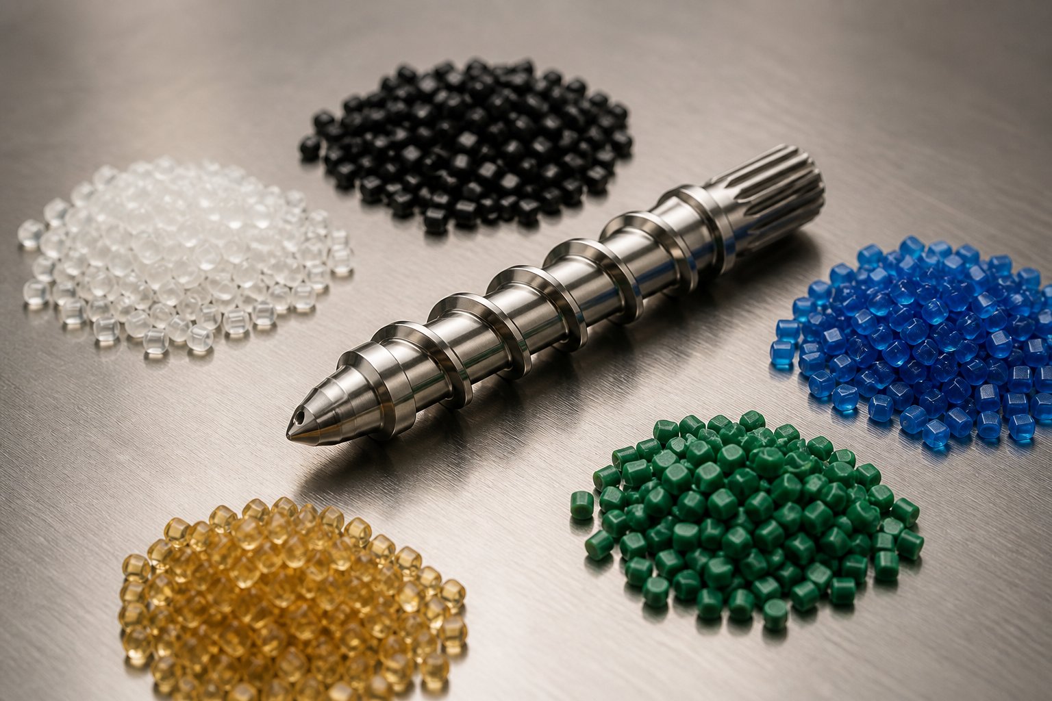
Metallurgy determines how long a screw lasts, but geometry determines how well it plasticates a specific polymer. A compression ratio that produces flawless polypropylene parts can leave nylon riddled with unmelts or scorch polycarbonate beyond salvageable clarity. Injection molding screw selection by resin type is not a secondary refinement — it is the single most impactful geometry decision you will make, because every polymer family brings its own melting behavior, shear sensitivity, and viscosity profile to the barrel.
Commodity and Engineering Resin Screw Configurations
Polyolefins (PE, PP) are the most forgiving resin family in injection molding. Both are semi-crystalline, but they have relatively broad melting ranges and low viscosities once molten. A standard GP screw with a compression ratio between 2.5:1 and 3.0:1 handles them comfortably. Higher L/D ratios — 22:1 to 26:1 — can improve melt homogeneity for large-shot applications without risking degradation, since polyolefins tolerate extended residence times well. For high-output production, a barrier screw further stabilizes melting by separating the solid bed from the melt pool, but for moderate volumes a GP design is more than adequate.
Engineering resins (nylon, POM, PBT) present a sharper challenge. These semi-crystalline polymers absorb significant energy at a narrow melting point, behaving more like ice than softening butter. If the screw cannot deliver that energy quickly and uniformly, solid fragments survive into the metering zone. The best injection screw for nylon processing is typically a barrier design with a compression ratio of 3.0:1 to 3.5:1 and a shorter, more aggressive transition zone. Resin-specific processing guides recommend keeping the gap between the check ring and barrel as small as possible — around 0.05 mm — because nylon's low melt viscosity makes it prone to leaking backward through worn seals. POM carries an added wrinkle: it releases formaldehyde at elevated temperatures, so the compression ratio should stay on the lower side of the range to avoid shear-driven overheating.
Amorphous resins (ABS, PC, PMMA) soften gradually across a wide temperature span rather than melting at a distinct point. This progressive transition favors longer compression zones with gentler tapers. For polycarbonate, the screw compression ratio for polycarbonate should sit around 2.0:1 to 2.6:1, paired with an L/D of 24:1 or higher to give the high-viscosity melt enough processing runway to homogenize fully. Technical references for PC processing suggest zone proportions of roughly L1 = 30%, L2 = 46%, with a mixing structure added before the metering section to help entrained moisture escape as gas. PMMA follows a similar philosophy — gradual screws with L/D ratios of 20:1 to 22:1 and compression ratios of 2.3:1 to 2.6:1 — since its high viscosity and hydrophilicity demand controlled energy input and effective moisture management.
Filled, Shear-Sensitive, and Bioplastic Resin Guidance
Glass-filled and mineral-filled compounds demand a dual focus: geometry for melt quality and metallurgy for survival. A screw design for glass filled compounds should incorporate mixing elements — a Maddock or pin section — downstream of the transition zone to redistribute filler particles that tend to segregate during melting. Compression ratios between 2.0:1 and 2.5:1 work well, since the filler particles themselves generate substantial shear heat during compression. Higher ratios risk fiber breakage in glass-reinforced grades, shortening the reinforcing fibers and weakening the finished part. As discussed in the metallurgy section, bimetallic barrels and hard-faced flight tips are non-negotiable for anything above 10% glass loading.
Heat-sensitive and shear-sensitive resins (PVC, TPU) sit at the opposite end of the processing spectrum. PVC's softening point is dangerously close to its decomposition temperature, so screws must minimize shear energy. PVC processing guidelines specify L/D ratios of 16:1 to 20:1, compression ratios as low as 1.6:1 to 2.0:1, and extended feed and transition zones (each around 40% of the flighted length) to spread energy input over the longest possible distance. Check rings are often eliminated entirely for PVC, replaced by a pointed screw tip with a 20-30 degree taper, because any dead spot traps material long enough to trigger degradation. TPU and TPE materials share PVC's shear sensitivity, though for different reasons — excessive shear degrades their elastomeric properties rather than causing chemical decomposition.
Bioplastics (PLA, PHA) represent a rapidly growing category with processing quirks that catch many molders off guard. PHA-based resins are especially challenging. Danimer Scientific's processing research confirms that PHA is shear-sensitive enough to resemble PVC in its tendency to cause temperature overruns in the compression zone, while its flow characteristics mimic nylon's propensity to flash at the smallest parting-line imperfection. Barrel temperatures are kept remarkably low — starting conditions range from 310-350 degrees F across zones — and even brief exposure above 400 degrees F causes rapid degradation. Low-compression GP screws with slow screw speeds are recommended, and material left sitting in a heated barrel for more than five minutes should be purged with fresh resin. PLA is somewhat more forgiving but still has a narrower processing window than petroleum-based polymers, benefiting from moderate compression ratios of 2.0:1 to 2.5:1 and gentle transition profiles that avoid localized hot spots.
The following quick-reference chart consolidates these resin-to-screw relationships into a single resource you can reference during screw specification or troubleshooting.
| Resin Family | Recommended Screw Type | Suggested Compression Ratio | Special Notes |
|---|---|---|---|
| Polyolefins (PE, PP) | GP screw; barrier screw for high output | 2.5:1 – 3.0:1 | Tolerant of higher L/D ratios (22:1–26:1); broad processing window |
| Nylon (PA6, PA66) | Barrier screw preferred | 3.0:1 – 3.5:1 | Sharp melt point; tight check-ring clearance (~0.05 mm) essential due to low melt viscosity |
| POM (Acetal) | Barrier or GP with moderate compression | 2.5:1 – 3.0:1 | Releases formaldehyde at elevated temps; avoid excessive shear and dead spots |
| PBT / PET | GP with low shear; no mixing section for PET | 1.8:1 – 2.5:1 | PET is highly temperature-sensitive; set hs = 0.09D to prevent discoloration |
| ABS | GP screw with moderate transition zone | 2.0:1 – 2.8:1 | Amorphous; gradual compression preferred; consider vented screw if moisture is persistent |
| Polycarbonate (PC) | GP with mixing element; gradual compression | 2.0:1 – 2.6:1 | High viscosity; L/D of 24:1+ recommended; add mixing ring to manage moisture |
| PMMA (Acrylic) | Gradual GP screw | 2.3:1 – 2.6:1 | Hydrophilic; mixing ring at screw tip aids moisture evacuation; L/D 20:1–22:1 |
| Glass-Filled Compounds | GP or barrier with mixing element (Maddock/pin) | 2.0:1 – 2.5:1 | Bimetallic barrel and hard-faced flights mandatory; excessive compression breaks fibers |
| PVC (Rigid and Flexible) | Low-shear GP; no check ring; pointed screw tip | 1.6:1 – 2.0:1 | L/D 16:1–20:1; corrosion-resistant metallurgy required; no dead spots |
| TPU / TPE | GP or distributive-mixing (pin) screw | 2.0:1 – 2.5:1 | Shear-sensitive; avoid Maddock mixers; gentle transition profile essential |
| PLA | GP with moderate compression | 2.0:1 – 2.5:1 | Narrower window than conventional resins; avoid prolonged residence time |
| PHA / PHA-PLA Blends | Low-compression GP; standard design | 1.8:1 – 2.3:1 | Degrades rapidly above 400°F; purge after 5 min idle; slow screw speeds mandatory |
You will notice that resin selection drives not just compression ratio and screw type, but also secondary considerations — check-ring configuration, mixing-element choice, L/D range, and even whether a check ring should be used at all. These secondary factors point to a broader truth: the screw never operates in isolation. Its performance is inseparable from the barrel, check ring, and nozzle surrounding it — an interaction that deserves its own careful examination.
How Injection Molding Screws Interact with Barrels and Machine Components
Even the most precisely engineered screw cannot deliver consistent melt quality on its own. It operates inside a system — barrel bore, non-return valve (check ring), screw tip, and nozzle — where every component's condition and design either reinforces or undermines the screw's intended performance. A screw geometry perfectly matched to your resin can still produce erratic shot weights if the check ring leaks, inconsistent melt if barrel bore wear has widened clearances, or excessive back pressure if the nozzle restricts flow. Treating these components as isolated parts rather than an integrated plasticating assembly is one of the most common — and costly — blind spots in injection molding troubleshooting.
Check Ring and Screw Tip Interaction
Imagine a one-way valve at the very front of your screw. That is essentially what the check ring — also called the non-return valve — does. During recovery, as the screw rotates and pushes molten polymer forward, the check ring slides open, allowing melt to flow through channels in the screw tip and accumulate in front of the assembly. When injection begins, the screw rams forward, and the check ring reverses direction to seat against a rear seal, blocking any backflow of melt toward the screw flights.
This sequence sounds simple, but its precision governs shot-to-shot repeatability. As ASACLEAN's technical team explains, an improperly functioning non-return valve allows material to slip past the seat during injection, causing the screw to creep forward and eroding control over consistent cavity packing. The result? Cushion instability, dimensional drift, and parts that fluctuate between overpacked and underpacked from shot to shot.
The most common check ring style — the sliding check ring — consists of three or four components: a retainer (tip), the check ring itself, and a rear seat. Component specialists note that four-piece designs, where the front seat is manufactured from a separate, harder material than the retainer, last longer and are more reliable because each wear surface can be optimized independently. Wear typically appears in two critical areas:
- Check ring outer diameter — As abrasive resins erode the ring's OD, the growing clearance between the ring and barrel wall allows melt to bypass the seal entirely. You will see this as a gradual loss of cushion consistency even when the seat surfaces are still intact.
- Rear seat contact surface — Corrosion, abrasive scoring, or exposure to unmelted pellets damages the sealing face, preventing a tight closure during injection. Even a minor imperfection here creates a leak path that worsens rapidly under injection pressure.
An early indicator of check ring trouble is shot-to-shot weight variation that seems negligible at first but steadily worsens. What makes this problem insidious is that operators often compensate by adjusting cushion settings or pack pressures rather than investigating the root cause. By the time compensation hits its limits, the wear has progressed far enough that the valve may need full replacement rather than simple reconditioning.
The check ring is also a notorious area for material hang-up and degradation. As processing engineers emphasize, restricted flow through the valve openings creates localized shear that is difficult to control or quantify. Even a small amount of added shear heat can trigger degradation, and color deposits from previous runs can remain trapped in the valve area, eventually contaminating subsequent production. Thorough cleaning of the check ring between jobs — not just the screw itself — is essential for preventing these quality failures.
Barrel Wear and Its Impact on Screw Performance
The barrel bore and screw flight OD form a working pair with extremely tight tolerances. On a new assembly, the radial clearance between flight tips and barrel wall is typically just 0.05-0.15 mm per side, depending on screw diameter. This tight gap is what allows the screw to build forward pressure and convey material efficiently. When that clearance opens up — through flight OD erosion, barrel bore enlargement, or both — the consequences cascade through the entire plasticating process.
As Stephen Surley of SpiraMelt Technologies details, increased radial clearance causes melt to leak backward over the flight tips rather than being conveyed forward. This leakage flow reduces effective plasticating rate, forcing operators to increase screw RPM to maintain output. Higher RPM generates more shear heat, which raises melt temperature beyond target — a compounding effect that quietly degrades part quality while simultaneously increasing energy consumption.
Where does wear concentrate? Contrary to the popular theory that screw flexion pushes flight tips against the barrel wall, the dominant driver is pressure-intensified friction. The transition section and the last few turns of metering consistently experience the highest pressures and temperatures in the barrel, and empirical inspection of thousands of screws confirms these are the zones where flight OD erosion is most severe. For filled resins, the feed section can also suffer heavy wear as glass fibers or mineral particles are compacted against the flight faces with limited lubrication from unmelted pellets.
A widely cited guideline considers a flight clearance four times the original tolerance to be the threshold for screw replacement. However, this rule of thumb overlooks a critical variable: resin viscosity. Higher-viscosity polymers resist leakage flow more effectively, so the same clearance produces less output loss with polyethylene than with polypropylene or nylon. The practical implication is that injection molding screw and barrel clearance thresholds should be adjusted based on the specific resin being processed, not applied as blanket standards.
Root wear — erosion of the screw's root surface between flights — creates an additional problem. Pockets and rough surfaces in the root area trap material, extending its residence time far beyond the screw's design intent. This stagnant material degrades, eventually releasing as black specks or contamination streaks in molded parts. In extreme cases, root wear undermines the structural support for hard-faced flight inlays, causing the brittle hardfacing material to chip off and damage downstream components.
Nozzle Design and Back-Pressure Interaction
The nozzle sits at the very end of the flow path, between the barrel and the mold sprue bushing, and it plays a more active role in plasticating performance than many processors realize. Two nozzle parameters — bore diameter and land length — create flow restriction that generates back pressure on the melt accumulated in front of the screw tip.
A smaller nozzle bore or a longer land length increases this restriction, raising the pressure the screw must overcome to push melt into the mold. This added resistance interacts directly with the pressure the screw generates during recovery and injection. If the nozzle restriction is too high, recovery time extends, melt temperature rises from the additional shear work, and the check ring must work harder to maintain its seal against elevated pressures. If the restriction is too low — an oversized bore with a short land — the melt sees almost no resistance, which can lead to drool at the nozzle tip and inconsistent shot density.
For most applications, the nozzle bore should be slightly smaller than the sprue bushing bore to ensure a clean seal, with land length proportional to the bore diameter. The key insight is that nozzle selection is not independent of screw design. A screw producing borderline melt pressure — due to wear, low compression ratio, or inadequate RPM — will amplify every ounce of additional nozzle restriction into a process problem. Conversely, a high-output barrier screw generating robust melt pressure can tolerate tighter nozzle geometries without performance loss.
Common Injection Molding Screw Myths Debunked
Misunderstandings about how these components work together give rise to persistent myths that cost processors time, money, and quality. Here are the most common — along with the reality behind each one:
- Myth: One screw fits all resins.
Reality: Every resin family has distinct melting behavior, shear sensitivity, and viscosity characteristics. A screw optimized for polyolefins will underperform or damage engineering polymers, and a PVC screw design is completely wrong for nylon. Resin-specific geometry matching, as detailed in the previous section, is not optional for consistent quality. - Myth: A higher compression ratio always means better mixing.
Reality: Higher compression increases shear energy input, which accelerates melting but does not inherently improve distributive mixing. For true color or additive uniformity, you need dedicated mixing elements — Maddock sections, pin mixers, or similar devices. Meanwhile, excessive compression ratios overheat shear-sensitive polymers, causing degradation rather than better homogeneity. - Myth: L/D ratio is the only parameter that matters.
Reality: L/D ratio influences residence time and total energy input, but it tells you nothing about how aggressively the screw compresses the melt (compression ratio), how well it seals against the barrel (flight-tip condition), or how effectively it prevents backflow (check ring condition). Two screws with identical L/D ratios but different compression ratios, flight geometries, and check ring configurations will produce dramatically different melt quality. - Myth: If the screw still turns, it is still working properly.
Reality: Screw wear is a gradual process that often goes unnoticed until performance is severely compromised. Operators compensate by adjusting RPM, back pressure, and temperatures — masking the underlying wear. By the time these adjustments can no longer hold quality, the screw may be too worn to recondition cost-effectively. - Myth: Barrel wear is the screw's fault.
Reality: Barrel bore enlargement results from the same abrasive and corrosive mechanisms that attack the screw, not from the screw itself. In fact, improperly matched metallurgies between screw and barrel — not the screw acting alone — are a primary cause of accelerated adhesive wear (galling) that damages both components simultaneously.
These myths share a common thread: they oversimplify a system that relies on the precise interaction of multiple components working within tight tolerances. When any element in that system — screw geometry, check ring seal, barrel bore, or nozzle restriction — drifts out of specification, the effects ripple through part quality in ways that process parameter adjustments alone cannot fix. Recognizing which defects trace back to component wear rather than process settings is a diagnostic skill that separates reactive troubleshooting from root-cause problem solving.
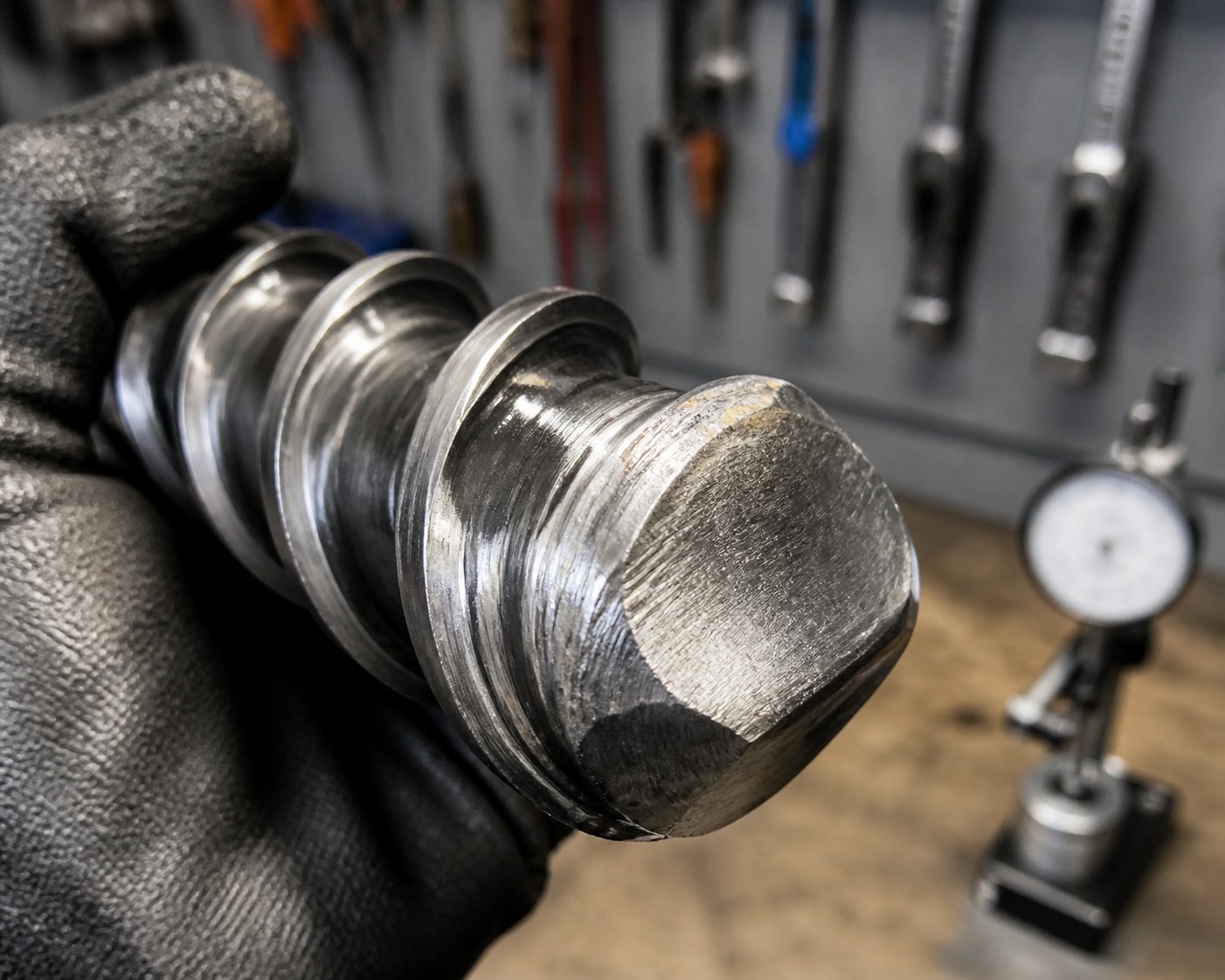
Troubleshooting Molding Defects Caused by Screw Wear or Geometry
A defect appears on a molded part, and the first instinct is to adjust the process — bump injection speed, raise barrel temperatures, increase pack pressure. Sometimes those tweaks mask the symptom for a few hundred shots. Then the defect returns, often worse. The frustrating truth is that many persistent injection molding defects caused by screw wear will never respond to process parameter changes, because the root cause is not a setting — it is a dimension. Worn flight tips, eroded check rings, and mismatched screw geometry create quality failures that look identical to process-driven problems, sending operators down troubleshooting rabbit holes that waste hours of production time.
What follows is a structured framework for connecting specific defects back to their screw-related origins and a practical protocol for measuring wear before it costs you more in scrap than a replacement would.
Defect-to-Screw-Cause Troubleshooting Matrix
When a quality issue resists standard process corrections, the plasticating assembly should move to the top of your investigation list. Each defect type below maps to a probable screw or check-ring cause, a diagnostic check you can perform without pulling the screw, and a corrective action to resolve the root issue.
| Defect Type | Possible Screw-Related Cause | Diagnostic Check | Recommended Corrective Action |
|---|---|---|---|
| Burn marks / brown streaks | Worn flight tips creating excessive clearance and localized shear; too-high compression ratio for the resin; material hang-up in damaged root areas or degraded check ring | Monitor melt temperature at the nozzle — if it reads significantly higher than barrel setpoints, excessive shear heating is likely. Check screw recovery time trends for gradual increases. Inspect purge shots for dark specks or discolored streaks. | Measure screw flight OD and barrel bore ID to confirm clearance. Replace or recondition screw if flight wear exceeds tolerance. If geometry is intact, evaluate whether the compression ratio is too aggressive for the resin and consider a lower-compression design. |
| Splay / silver streaks | Worn or damaged check ring allowing melt backflow that traps moisture or volatiles; inadequate decompression or venting on two-stage screws; excessive screw RPM generating gas through frictional heat | Verify that material is dried to spec — if splay persists even with properly dried resin, the screw assembly is suspect. Check cushion stability: erratic cushion values point to check-ring leakage. Industry troubleshooting guides recommend reducing screw RPM and increasing back pressure to test whether volatile generation decreases. | Inspect and replace the check ring and rear seat if sealing surfaces show scoring or corrosion. On vented screws, verify that the decompression zone depth is sufficient and that the vent port is not blocked. Lower screw speed and confirm back pressure is high enough to expel trapped gas rearward through the hopper. |
| Unmelted particles / unmelts | Insufficient L/D ratio for the resin; incorrect compression ratio leaving solid fragments in the metering zone; worn metering-zone flights reducing shear input; barrier flight wear allowing solids to bypass the melt channel | Examine purge shots under magnification for translucent or opaque specks embedded in the melt. Compare current recovery time and back pressure to baseline values — a worn metering zone requires more revolutions to achieve the same melt quality. Check if the problem worsens at higher throughput rates, which indicates a melting-capacity ceiling. | If the screw geometry matches the resin but performance has degraded, measure metering-zone flight OD for wear. If geometry is inherently mismatched — e.g., a low-compression GP screw running semi-crystalline nylon — replace with a barrier screw or higher-compression design. Increasing back pressure and reducing screw RPM can provide temporary relief but will not resolve a fundamental geometry mismatch. |
| Short shots / incomplete fill | Reduced plasticating capacity from worn screw flights leaking melt backward; check-ring backflow during injection reducing effective shot volume; severely worn metering zone unable to build adequate head pressure | Track shot weight across 20-30 consecutive cycles. Wear-tolerance specialists identify unstable cushion, longer recovery time, and inconsistent shot weight as hallmark symptoms of excessive clearance. Compare actual shot weight to theoretical shot volume — a significant gap confirms volumetric efficiency loss. | Measure flight-to-barrel clearance at all three zones. If diametrical clearance exceeds roughly 3-4 times the original design gap, the screw has lost enough sealing efficiency to cause volumetric shortfalls. Replace the check ring first (the most common single-component cause of short shots), then evaluate screw and barrel dimensions for reconditioning or replacement. |
| Color streaks / poor pigment distribution | Lack of dispersive or distributive mixing elements on the screw; worn mixing section (Maddock flutes or pin elements) that no longer generates adequate shear or flow splitting; dead spots in a damaged check ring trapping previous color | Run a color-change purge and observe how many shots are needed to clear the previous color. Excessive purge cycles indicate material hang-up. Mold parts with a contrasting masterbatch and examine cross-sections for streaking patterns — concentrated streaks near the part core suggest incomplete radial mixing. | Add a Maddock or pin mixing section if the current screw lacks one. If a mixer is present but worn, inspect the shear-dam clearances and flow-channel condition. Thoroughly clean or replace the check ring assembly to eliminate hang-up zones. For shear-sensitive resins, choose a distributive (pin) mixer over a dispersive (Maddock) design to avoid thermal damage. |
A pattern runs through this matrix: many defects that appear to be process problems are actually geometry or wear problems masquerading as process instability. The distinguishing clue is usually progression over time. A process-related burn mark tends to appear suddenly after a parameter change. Burn marks from a worn injection screw worsen gradually over weeks or months, resisting every temperature and speed adjustment you throw at them. If the defect has been creeping in and getting harder to manage, measure the hardware before chasing more process variables.
Wear Measurement and Diagnostic Protocols
Suspecting wear and confirming it are two different things. Reliable diagnosis requires actual dimensional data — not guesswork based on how the screw looks after pulling it from the barrel. Here is a step-by-step protocol for how to measure injection screw wear accurately and translate those numbers into an actionable decision.
Step 1: Clean and cool both components. Residual polymer distorts readings and can add hundredths of a millimeter to every measurement. Remove the screw from the barrel, purge both components thoroughly, and allow them to cool to room temperature. Inspection protocols emphasize that even thin polymer films on flight tips or inside the bore can skew micrometer and bore-gauge readings enough to produce misleading clearance values.
Step 2: Measure screw flight OD at multiple axial positions. Using an outside micrometer, take readings at the feed zone, transition zone, mixing section (if present), and metering zone. At each axial position, measure across at least two perpendicular directions to detect eccentric wear or screw bending. Also inspect flight edges — rounded or visibly eroded flight lands are a clear sign that the hard case layer has worn through, exposing softer base metal underneath.
Step 3: Measure barrel bore ID at corresponding positions. Insert a bore gauge or internal micrometer at the same axial stations used for the screw. Take readings at several clock positions (0, 90, 180, and 270 degrees) to identify not just enlargement but ovality — a barrel that has worn into an oval cross-section cannot be corrected by screw replacement alone. Pay special attention to the transition and metering zones, which field data consistently shows as the highest-wear areas due to peak pressure and temperature.
Step 4: Calculate diametrical and radial clearance. Pair every barrel ID reading with the corresponding screw OD measurement:
- Diametrical clearance = Barrel ID - Screw flight OD
- Radial clearance = (Barrel ID - Screw flight OD) / 2
Always specify which value you are reporting. Confusing diametrical and radial clearance — a surprisingly common error — can double or halve the apparent severity of the wear and lead to the wrong repair decision.
Step 5: Compare against screw flight OD wear tolerance limits. A widely referenced industry guideline flags clearance at roughly three to four times the original design gap as the threshold for corrective action. For a screw originally designed with 0.10 mm radial clearance per side, that threshold would fall around 0.30-0.40 mm radial — or 0.60-0.80 mm diametrical. However, as discussed in the previous section, resin viscosity matters: low-viscosity melts like nylon leak backward more readily at a given clearance than high-viscosity melts like polycarbonate, so tighter thresholds apply for low-viscosity processing.
Step 6: Decide — recondition or replace? This is where the numbers meet economics. Several factors weigh into the decision:
- Reconditioning is viable when the screw body is straight (no measurable runout), the root surface is intact without deep scoring or pitting, and the wear is concentrated at the flight tips. Hard-facing the flight lands with a wear-resistant alloy and grinding them back to specification restores the sealing surface. Re-nitriding can also extend the life of a lightly worn screw if the original case layer has thinned but not fully breached.
- Replacement is necessary when root wear has created deep channels or rough pockets that trap material, when the screw shows measurable bending or runout, when coatings have peeled or flaked (exposing base metal across large areas), or when the wear pattern indicates a fundamental geometry mismatch that reconditioning cannot correct. Wear diagnostics experts also flag exposed base metal, one-sided wear from misalignment, and barrel cracks as conditions that typically require component replacement rather than repair.
Replacing a worn screw without measuring the barrel is a common and expensive mistake — a new screw installed in a worn barrel will underperform from day one and wear prematurely because the oversized bore eliminates the tight clearance the screw depends on for efficient plasticating.
The barrel and screw must always be evaluated together. If barrel bore measurements reveal significant enlargement or ovality, honing or relining the barrel — or replacing it alongside the screw — is the only way to restore the tight-clearance system both components require. Treating them as independent parts rather than a matched pair is a shortcut that guarantees premature failure of whichever component you did replace.
Catching wear before it drives scrap rates up — and making the right call on reconditioning versus replacement — ultimately comes down to how consistently you inspect, how accurately you measure, and how strategically you plan for the inevitable end of every plasticating component's service life.
Screw Maintenance, Lifecycle Economics, and Replacement Strategy
Knowing how to measure wear and diagnose screw-related defects is valuable — but only if those skills are embedded into a repeatable maintenance program rather than deployed as emergency responses after quality has already collapsed. The gap between reactive troubleshooting and proactive lifecycle management is where most injection molding operations lose the most money. Not in catastrophic failures, but in the slow accumulation of scrap, extended cycles, and energy waste that a gradually degrading plasticating assembly generates over months or years of neglected inspection.
An effective injection molding screw maintenance schedule transforms wear from an unpredictable crisis into a manageable, budgetable operating expense. The sections below lay out a practical framework covering inspection intervals, the economics of reconditioning versus full replacement, and how to source components that match your exact application requirements.
Preventive Maintenance and Inspection Best Practices
Most facilities structure their maintenance calendars around daily, weekly, and monthly intervals — and that approach works for hydraulic checks and safety interlocks. Screw and barrel inspections, however, follow a different rhythm. Wear rates depend on resin abrasiveness, filler content, operating hours, and processing temperatures rather than calendar dates. A machine running unfilled polypropylene eight hours a day wears its plasticating components far more slowly than one running 30% glass-filled nylon around the clock.
The following workflow organizes screw maintenance into a tiered system based on both time intervals and condition triggers. Treat it as a starting framework, then adjust intervals based on your specific resin portfolio and historical wear data.
- Every shift — Monitor process indicators. Track recovery time, cushion position, and shot-weight consistency. These are your earliest warning signals. A gradual increase in recovery time or a widening shot-weight range often indicates developing clearance issues weeks before defects become visible in parts.
- Monthly — Inspect purge quality and melt appearance. Run a clean purge cycle and examine the extrudate for black specks, discoloration, or unmelted particles. Document the results photographically so you can compare month-over-month trends. Degradation products and contamination streaks point to material hang-up in the check ring or damaged screw root areas.
- Quarterly — Verify check ring performance. Perform a cushion-consistency test: run 20-30 consecutive shots at stable conditions and measure cushion variation. Variation exceeding +/- 1 mm on most machines indicates the non-return valve is no longer sealing effectively. This check takes minutes and can prevent weeks of chasing phantom process instability.
- Annually (or every 3,000-5,000 operating hours) — Pull the screw for dimensional inspection. As structured maintenance programs recommend, an annual screw pull should include measuring flight OD, barrel bore ID, and check-ring dimensions against baseline values. Look for carbon buildup, uneven wear patterns, and root-surface damage. Compare measurements to the wear-tolerance thresholds discussed in the troubleshooting section above.
- After every resin change involving abrasive or corrosive materials — Conduct a targeted inspection. Running even a short campaign of glass-filled resin through a screw designed for unfilled materials can accelerate wear disproportionately. A quick dimensional spot-check after these runs catches damage before it compounds.
- Before extended storage — Clean, coat, and protect. If a screw will sit idle for more than a few weeks, purge all residual polymer, apply a light coat of corrosion-inhibiting oil to all surfaces, and store the component horizontally on V-blocks or in a protective rack to prevent bending from its own weight. Moisture and residual resin acids left on unprotected steel surfaces cause pitting corrosion that can render an otherwise serviceable screw unusable.
Discipline in recording these measurements is just as important as taking them. A single set of numbers tells you where things stand today. A history of measurements tells you the wear rate — how fast clearances are opening — which is what you actually need to predict when to replace injection molding screw components before they start costing more in scrap and downtime than a new set would.
Reconditioning vs. Replacement Decision Framework
Every worn screw presents the same question: is it more cost-effective to recondition this component or replace it outright? The answer depends on what the measurements reveal and how those findings interact with production economics.
When reconditioning makes sense:
- The screw body is straight with no measurable runout or bending.
- Wear is concentrated at the flight tips, and the root surface remains smooth and dimensionally sound.
- The nitrided case has thinned but has not fully breached across large areas of the flight lands.
- The screw's geometry — compression ratio, L/D, zone proportions — is still correct for your current application.
Under these conditions, hard-facing the flight tips with a wear-resistant alloy (such as Colmonoy 56 or a stellite-based material) and grinding them back to original OD specifications restores sealing efficiency at a fraction of full replacement cost. Re-nitriding can also extend the service life of lightly worn screws by rebuilding the hard surface case. Screw reconditioning vs replacement cost comparisons typically show reconditioning at 40-60% the price of a new screw, making it an attractive option when the underlying structure is still solid.
When replacement is the better investment:
- Root wear has created deep grooves, pitting, or rough pockets that trap and degrade polymer.
- The screw shows measurable bending, indicating it has been subjected to misalignment or excessive side loads.
- Hard-facing has already been applied once or twice previously, and the flight geometry can no longer be ground back to specification without compromising the base material.
- The current screw geometry is a mismatch for your application — for example, you have shifted to a more abrasive resin family or a different part requiring tighter tolerances — and reconditioning would only restore an already suboptimal design.
- Barrel bore measurements show significant enlargement or ovality, meaning a reconditioned screw would be installed into a worn barrel and underperform immediately.
One often-overlooked factor in this decision is total cost of ownership rather than purchase price alone. A cheaper reconditioned screw that lasts 6 months before needing attention again may cost more per operating hour than a new screw engineered with premium metallurgy that runs 18-24 months. Investing in the correct geometry and material upfront — matching compression ratio to your resin, selecting appropriate wear-resistant coatings for your filler loading — typically reduces cycle times by 5-15%, lowers scrap rates, and decreases energy consumption over the component's full service life. Those savings compound across thousands of operating hours, often dwarfing the initial price difference between a generic replacement and a purpose-engineered solution.
Sourcing Custom and Replacement Screw Barrels
Here is where many maintenance engineers hit a practical bottleneck. The original equipment manufacturer may have long lead times, limited options for custom geometries, or no longer support older machine models. Generic replacement screws fit the barrel physically but may use a one-size-fits-all compression ratio and standard nitrided steel — adequate for basic commodity resins but incapable of delivering the performance a specific application demands.
Working with a custom injection molding screw barrel manufacturer changes this equation. A manufacturer capable of engineering screws to your exact specifications can match compression ratio, L/D, zone proportions, and flight geometry to the resin you actually process — not the average resin the OEM assumed when the machine shipped. Metallurgy can be tailored as well: nitrided steel for unfilled polymers, bimetallic barrels and hard-faced flights for glass-filled compounds, or corrosion-resistant alloys for PVC and fluoropolymer work.
For injection molding factories, machine rebuilders, and maintenance teams sourcing replacement plasticizing components or custom-manufactured screw and barrel sets, NANHAIYA's injection molding screw barrel line offers purpose-built options designed to match specific machine platforms and application requirements. Rather than settling for generic replacements that restart the cycle of premature wear and suboptimal melt quality, custom-manufactured components let you build the exact geometry and metallurgy combination your process data tells you it needs.
Regardless of your sourcing path, always provide the manufacturer with your baseline dimensional data, the resin families you run, filler types and loading percentages, and your measured wear patterns from previous screws. This information transforms a parts order into an engineering conversation — and the resulting component will outperform and outlast anything selected from a catalog page without context.
The plasticating screw may be buried inside the barrel where nobody sees it, but its condition and design ripple outward into every metric your operation tracks: part quality, cycle time, energy cost, and scrap rate. Treating it as a consumable to be replaced only when it fails misses the point entirely. Managed proactively — inspected on schedule, measured against baselines, reconditioned or replaced strategically, and sourced to match your actual processing demands — the screw becomes one of the most controllable variables in your entire production system.
Frequently Asked Questions About Injection Molding Screws
1. What is the difference between a general-purpose screw and a barrier screw in injection molding?
A general-purpose (GP) screw uses a single-flight, three-zone design suitable for commodity resins like PE, PP, and PS, offering broad versatility at a lower cost. A barrier screw adds a secondary barrier flight in the transition zone that physically separates unmelted solids from the melt pool. This dual-channel architecture virtually eliminates unmelted particles from reaching the metering zone, making barrier screws the preferred choice for semi-crystalline engineering resins such as nylon, PBT, and POM that have sharp melting points. Barrier screws also deliver higher output consistency at elevated production speeds, though they cost more and are less flexible for frequent material changeovers.
2. How do you calculate the compression ratio of an injection molding screw?
The compression ratio is calculated by dividing the channel depth in the feed zone by the channel depth in the metering zone. For example, a screw with a 6.0 mm feed-zone depth and a 2.0 mm metering-zone depth has a compression ratio of 3.0:1. This ratio determines how much volume reduction and shear energy the resin experiences during plasticating. Standard GP screws typically use ratios between 2.5:1 and 3.0:1. Semi-crystalline resins may need higher ratios (up to 3.5:1), while heat-sensitive materials like PVC require much lower ratios (1.6:1 to 2.0:1) to prevent thermal degradation.
3. How often should injection molding screws be inspected for wear?
Effective maintenance uses a tiered approach rather than a single fixed interval. Process indicators like recovery time, cushion stability, and shot-weight consistency should be monitored every shift. Monthly purge inspections help detect black specks or degradation signs. Check-ring performance should be verified quarterly through cushion-consistency testing across 20-30 consecutive shots. A full dimensional inspection — pulling the screw to measure flight OD, barrel bore ID, and check-ring surfaces — is recommended annually or every 3,000 to 5,000 operating hours. Shops processing abrasive glass-filled or mineral-filled resins should shorten these intervals based on historical wear-rate data. Partnering with a specialized manufacturer like NANHAIYA for custom replacement screw barrels ensures precise geometry and metallurgy matching when components reach end of life.
4. What causes unmelted particles in injection molded parts?
Unmelted particles — also called unmelts or fisheyes — typically stem from screw-related causes rather than barrel temperature settings alone. The most common culprits include an insufficient L/D ratio that does not provide enough residence time for complete melting, a compression ratio too low for the resin's melting characteristics, worn metering-zone flights that reduce shear input, or barrier-flight erosion that allows solid pellets to bypass the melt channel. To diagnose, examine purge shots under magnification and compare current recovery times to baseline values. If the problem worsens at higher throughput rates, it signals a melting-capacity limit. Corrective actions include upgrading to a barrier screw design for semi-crystalline resins or replacing a worn screw whose metering-zone flights can no longer generate adequate shear.
5. What is the best screw material for processing glass-filled resins?
Glass-filled resins are highly abrasive and require premium metallurgy on both the screw and barrel side. For the barrel, a bimetallic lining with nickel and tungsten carbide particles is the industry standard, offering two to five times the bore life of iron/boron linings. On the screw side, hard-faced flight tips using Colmonoy 56 or stellite-based alloys provide a durable running surface, while CPM powder metallurgy steels such as CPM 9V or 10V deliver the longest service life for heavily filled compounds above 30% glass loading. Standard nitrided 4140 steel erodes too quickly under these conditions, often showing measurable flight-tip wear within weeks. Selecting appropriately matched screw and barrel materials is one of the highest-ROI decisions, and working with a custom screw barrel manufacturer ensures both components are engineered as a compatible system.
Written by
Nanhaiya Technical Team
Zhoushan Nanhaiya Plastic Machinery Co., Ltd.
The Nanhaiya technical team supports screw and barrel manufacturing projects through application review, technical communication, custom manufacturing coordination, and production and quality control.
Discuss Your Application
Related Articles
More insights on screw barrel technology and plastics processing.

What Nobody Tells You About Screw Barrel For Plastic Machine Design
Oct 10, 2026
Learn how screw barrel for plastic machine design affects melt quality, throughput, and wear life. Covers geometry, resin matching, troubleshooting, and sourcing.
Read Article
Single Screw Extruder for Sheet: Stop Guessing, Start Specifying
Oct 9, 2026
Learn how to specify a single screw extruder for sheet production. Covers screw geometry, resin-specific processing, troubleshooting, and maintenance best practices.
Read Article
PE Pipe Extruder Machine: What Datasheets Won't Tell You
Oct 9, 2026
Learn how a PE pipe extruder machine works, key specs explained, material grade selection, maintenance tips, and buyer guidance beyond the datasheet.
Read ArticleLooking for something else?
Search by material, symptom or product and jump straight to the relevant page.
These are navigation suggestions based on keyword matching — not a quotation, not a delivery commitment, and not a substitute for engineering review. Final specification is confirmed by our engineers against your drawings and processed material.
Need help with screw barrel selection?
Share your machine model, processed material and application. Our team can help with pricing and technical support.