

Draft Angles, Slides, and Screw-Off Mechanisms in Injection Molding
Imagine you're designing a plastic part with threaded features, side holes, and textured walls. You send the CAD file to your mold maker and get back a quote loaded with line items for slides, unscrewing actions, and draft modifications you didn't anticipate. Sounds familiar? The reason this happens is that three foundational mold design concepts - draft angles, side-action slides, and screw-off mechanisms - are deeply interconnected, yet most resources treat them as if they exist in separate universes.
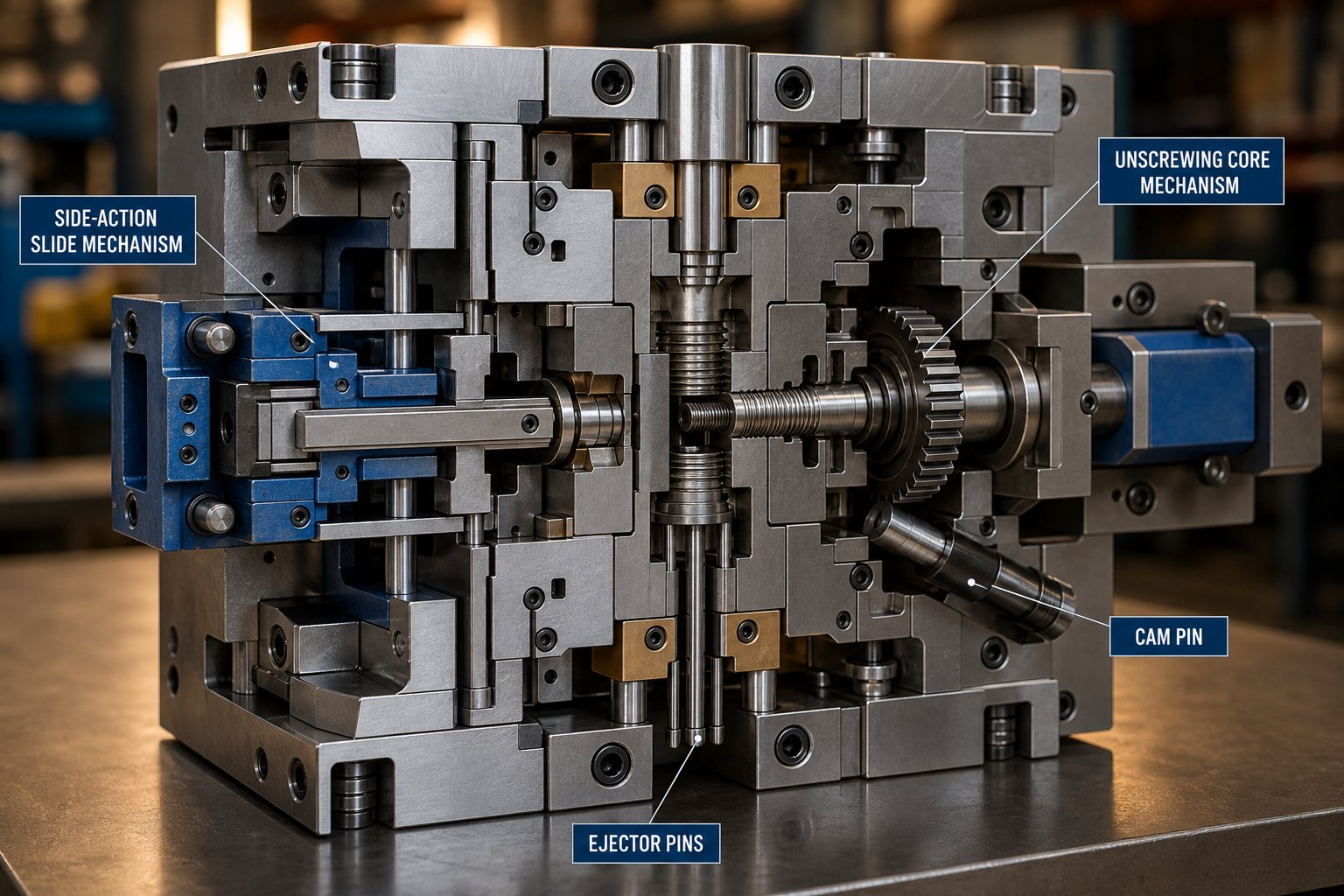
Draft angle is the slight taper applied to part walls so the molded piece releases cleanly from the mold without scuffing or sticking. Side-action slides are mechanical inserts driven laterally by cam pins or hydraulic cylinders to form external undercut features that a straight-pull mold simply cannot create. Screw-off (unscrewing) mechanisms are rotating drive systems - powered by rack-and-pinion gears, hydraulic motors, or electric servos - that spin a threaded core out of the molded part, enabling damage-free ejection of internal or external threads.
What Draft Angles, Slides, and Screw-Off Mechanisms Actually Mean
A draft angle is measured between the part wall and the mold's line of draw, typically ranging from one to two degrees per side. Without it, the part shrinks onto the core during cooling and resists ejection - leading to drag marks, warping, or outright stuck parts. Every vertical surface in a mold needs draft unless you have a very specific reason to go without it.
Side action injection molding comes into play when part geometry includes features perpendicular to the main parting line. As Xometry notes, these inserts collapse into place via a cam as the tool closes and pull away as it opens, forming undercuts like side holes, snap-fit hooks, and bayonet tabs that would otherwise be impossible. Screw-off cores take complexity a step further: they automate the removal of threaded parts that can't be ejected with stripper plates or pins because threads are, by definition, continuous undercuts wrapping around a helix.
Why These Three Concepts Belong Together
Here's what most guides miss: the keyword cluster injection molding screw off slide draft isn't three random topics. It represents an escalation path that mold designers and part engineers navigate on nearly every project. You start with draft - the simplest, cheapest variable. When draft alone can't free the part, you escalate to a slide. And when the geometry involves helical threads that no linear slide can handle, you reach for an unscrewing mechanism. Each level builds on the one before it, and each carries its own draft angle requirements that interact with the mechanism's movement.
The trouble is, you'll rarely find a single resource that connects these dots. Competitor guides explain slides in one article and unscrewing molds in another, leaving you to piece together how draft applies differently to each. This article closes that gap - walking you through the fundamentals, the material-specific nuances, and the decision framework that ties everything together.
The logical starting point? Understanding exactly how draft angles work at the most fundamental level - and why even a fraction of a degree can make or break your ejection.
Draft Angle Fundamentals Every Mold Designer Must Know
A fraction of a degree sounds insignificant - until it's the difference between a part that pops out of the mold cleanly and one that sticks, scuffs, or cracks during ejection. The injection molding draft angle is one of the simplest concepts in mold design, yet it remains one of the most frequently underestimated. Getting it right requires understanding not just what draft is, but why plastic parts fight so hard to stay inside the mold in the first place.
Three forces work against you the moment the mold opens. First, thermoplastic materials shrink as they cool, and that shrinkage grips the core steel like a fist tightening around a handle. Second, vacuum forces develop between the part surface and the mold wall, especially on deep, flat geometries where air can't easily backfill the gap. Third, surface friction resists any sliding motion between the solidified plastic and the polished or textured mold steel. Draft counters all three forces by creating a slight angular clearance that breaks the part free the instant the mold begins to open.
Without adequate draft, ejection forces spike. That extra force travels through ejector pins and into the still-warm part, causing pin push marks, warping, or even fractures. In extreme cases, the part refuses to release at all - and the mold itself can sustain damage. As Protolabs points out, an absence of draft may prevent parts from ejecting from the mold, potentially damaging not only the parts but possibly the mold itself.
How Draft Angle Is Measured and Applied
Draft angle in injection molding is always measured from the vertical - the line parallel to the mold's direction of pull. Picture a perfectly straight wall running exactly parallel to the way the mold opens and closes. That wall has zero degrees of draft. Tilt it inward by one degree, and you've created a taper that widens toward the parting line. That single degree is your draft angle.
The widely accepted industry baseline is one to two degrees per side for most features. A practical rule of thumb referenced across mold shops is roughly one degree of draft per inch of cavity depth. Deeper features need proportionally more taper to maintain the same ease of release. Protolabs' guidelines reinforce this baseline while noting that 0.5 degrees on all vertical faces is strongly advised as an absolute minimum.
Can you get away with zero draft? Technically, yes - in very specific situations. Short, shallow features on highly polished mold surfaces using low-shrinkage resins can sometimes eject without taper. But zero-draft designs are inherently risky. They leave no margin for the slight dimensional variations that occur naturally across production runs, and they dramatically increase sensitivity to process fluctuations like packing pressure and cooling time. Even as little as 0.25 degrees is a meaningful improvement over zero, reducing ejection resistance enough to give your process some breathing room.
Core-Side Versus Cavity-Side Draft Requirements
Here's where many part designers get caught off guard: the two halves of the mold don't behave the same way during cooling. The cavity side forms the outside of your part, while the core side forms the inside. As the plastic solidifies, it shrinks - and that shrinkage pulls the part away from the cavity walls but onto the core. The result? Internal features grip the core far more aggressively than external features grip the cavity.
This difference means core-side geometry consistently demands more draft than cavity-side geometry. A practical guideline supported by Freeform Polymers is to add 0.5 to 1 degree of additional draft to core-side features beyond whatever baseline you're using for the cavity side. The deeper or taller the feature, the more critical this adjustment becomes because height amplifies the total surface area gripping the steel.
Ribs, bosses, and hollow sections are the highest-risk zones. Each has its own draft considerations tied to geometry and wall thickness:
- Ribs: Keep rib base thickness at roughly 50% to 60% of the intersecting wall thickness to avoid sink marks. Apply at least 0.5 to 1 degree of draft per side, and increase that value for ribs deeper than one inch. Taller ribs amplify shrinkage grip and are harder to vent, making generous draft even more important.
- Bosses: Follow the same wall-thickness percentage guidelines as ribs. Bosses are essentially cylindrical ribs, and their height-to-diameter ratio directly influences ejection resistance. Reinforce tall bosses with gussets rather than increasing wall thickness, and apply draft to both the inner bore and outer diameter.
- Cup-shaped or hollow features: These wrap around the core on multiple sides, multiplying the shrinkage grip. They represent the most draft-sensitive geometry on most parts and often require the upper end of the recommended range.
Wall thickness also enters the equation. Thicker walls store more heat, cool more slowly, and shrink more overall - which translates to greater clamping force on the core. If your design requires thicker walls in specific regions, compensate with additional draft on those features rather than relying on higher ejection force to brute-force the part out.
What happens when even generous draft can't free a feature? That's precisely the scenario where side-action slides and lifters enter the conversation - and where material selection starts reshaping the entire draft strategy.
Material-Specific Draft Angle Guidelines with Surface Finish Adjustments
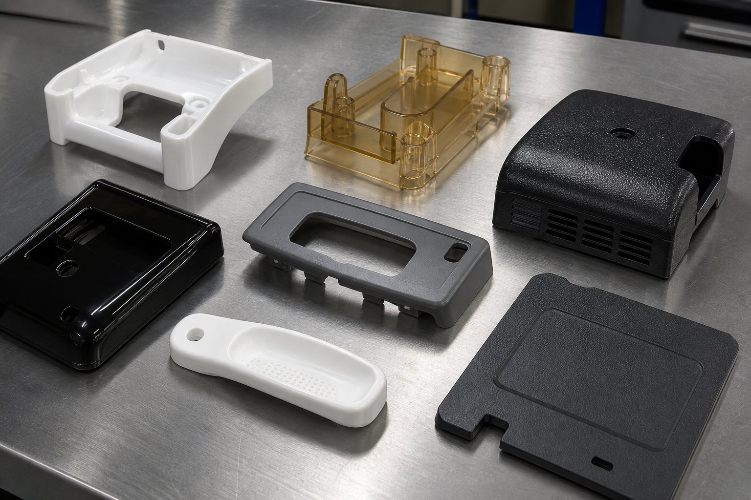
Knowing that one to two degrees is the baseline is helpful - but which resin are you molding? That question changes everything. A polypropylene cap and a 30% glass-filled nylon structural bracket live in completely different worlds when it comes to shrinkage behavior, surface friction, and ejection resistance. Yet most plastic part design for injection molding guides hand you a single generic draft recommendation and call it a day.
The reality is that each resin family has its own shrinkage rate, coefficient of friction against tool steel, and stiffness profile - all of which directly affect how aggressively the part grips the mold during cooling. Flexible materials like TPE can deform slightly during ejection, tolerating tighter angles in some cases. Rigid, abrasive materials like glass-filled nylon fight back much harder. A structured, material-by-material breakdown is the only way to set draft angles for injection molding with confidence rather than guesswork.
Draft Angle Recommendations by Resin Family
The table below consolidates widely accepted industry ranges drawn from resin supplier datasheets and production experience. You'll notice that the columns separate walls, ribs and bosses, and textured or slide-formed surfaces - because each feature type carries different risk levels, as covered in the previous section.
| Resin Family | Min. Draft for Walls | Draft for Ribs & Bosses | Draft for Textured / Slide-Formed Surfaces | Key Notes |
|---|---|---|---|---|
| ABS (General Purpose) | 0.5° - 1° | 1° - 1.5° | 2° - 3°+ | Low shrinkage; forgiving on polished surfaces but sensitive to texture depth |
| Polypropylene (PP) | 1° - 1.5° | 1.5° - 2° | 2.5° - 3.5°+ | Higher shrinkage than ABS; semi-crystalline structure increases core grip |
| Polycarbonate (PC) | 1° - 2° | 1.5° - 2.5° | 3° - 4°+ | High stiffness and elevated shrinkage; demands generous draft on deep features |
| Glass-Filled Nylon (PA6/66 GF30) | 1° - 2° | 1.5° - 2.5° | 3° - 5°+ | Abrasive glass fibers increase ejection friction and accelerate mold wear |
| TPE / TPU (Shore A 40-90) | 1° - 3° | 2° - 3° | 3° - 5°+ | Elastic recovery allows lower draft on short features; tall cores still need full draft |
| Polyethylene (PE) | 0.5° - 1.5° | 1° - 2° | 2° - 3°+ | Self-lubricating properties reduce friction; semi-crystalline shrinkage still applies |
| POM (Acetal) | 1° - 2° | 1.5° - 2.5° | 3° - 4°+ | High shrinkage and high crystallinity; zero-draft is extremely risky |
A few patterns jump out immediately. Glass-filled resins consistently demand more draft than their unfilled counterparts. The glass fibers increase the material's abrasiveness, causing greater friction against the mold steel during ejection. That friction translates directly into higher ejection forces - and if your draft doesn't compensate, you'll see drag marks, stuck parts, and accelerated tool wear. As a practical benchmark, production data from experienced molders suggests glass-filled nylon typically requires a minimum of 1 to 2 degrees on smooth walls, scaling up sharply once texture is involved.
On the opposite end, flexible TPE materials can sometimes tolerate slightly less draft on short, shallow features because the material deforms elastically as it clears the core. But don't let that forgiveness lure you into complacency - tall cores and deep ribs in TPE still demand the same or even more draft than rigid plastics, because the material's flexibility can cause it to buckle or distort during ejection rather than sliding cleanly off the steel.
Polypropylene sits in a tricky middle ground. Its relatively high shrinkage rate (typically around 1.5% to 2%) means parts grip cores aggressively, yet its semi-flexible nature lets it survive slightly lower draft on cavity-side walls. The risk is underestimating how much the part contracts onto internal features. PP bosses and deep ribs are common culprits for sticking, and bumping draft to 1.5 to 2 degrees on those features is well-supported practice.
How Surface Finish Changes the Draft Equation
Here's a variable that trips up even experienced designers: the surface texture you specify on your part directly alters how much draft you need. A polished, mirror-like finish (SPI A-class) lets the part slide against smooth steel with relatively low friction. A heavy leather-grain or geometric texture, on the other hand, creates thousands of microscopic undercuts between the plastic surface and the mold steel. Those tiny undercuts resist ejection just like a macro-scale undercut would - they simply do it across the entire textured area.
The widely applied guideline is roughly one additional degree of draft per 0.025 mm (0.001 inch) of texture depth. Some practitioners and surface finish standards use slightly different ratios - Fictiv's guidelines reference 1.5 degrees per 0.001 inch for certain textures - but the core principle holds: heavier textures always demand more draft. Here's how that plays out across common finish standards:
| Surface Finish Standard | Typical Texture Depth | Approximate Additional Draft Required |
|---|---|---|
| SPI A-1 to A-3 (High Polish) | Minimal (mirror finish) | +0° to +0.5° (standard draft usually sufficient) |
| SPI B-1 to B-3 (Semi-Gloss) | Light surface marks | +0.5° to +1° |
| SPI C-1 to C-3 (Matte / Stone) | ~0.01 - 0.02 mm | +0.5° to +1° |
| SPI D-1 to D-3 (Textured / Blasted) | ~0.02 - 0.08 mm | +1° to +3° |
| Mold-Tech MT-11010 (Light Texture) | ~0.025 mm | +1° to +1.5° |
| Mold-Tech MT-11020 (Medium Texture) | ~0.05 mm | +2° to +2.5° |
| Heavy Leather / Geometric Patterns | 0.08 mm+ | +3° to +5° or more |
What most resources fail to mention is that this texture-to-draft relationship applies equally to slide-formed and screw-off-formed surfaces. When a side-action slide shapes a textured pocket on the exterior of a housing, the texture on that slide core needs the same additional draft as a texture on the main cavity wall - sometimes more, because the slide's lateral retraction path creates a slightly different friction vector than a straight vertical pull. The same logic holds for screw-off cores that form textured non-threaded sections adjacent to threads. Ignoring texture draft on these mechanisms is a direct path to drag marks and premature tool wear on components that are already expensive to maintain.
Think of it this way: the plastic part design draft wall thickness standard you follow for your main cavity walls should be your starting point for every forming surface in the mold, regardless of which mechanism shapes it. Then layer on the material-specific adjustment from the first table and the texture-depth adjustment from the second. Stack those two corrections together, and you'll have a draft value grounded in both the resin's behavior and the surface it's being asked to release from.
This layered approach to draft is especially critical once your mold introduces moving components - slides and unscrewing cores - that add mechanical complexity on top of the material and surface challenges. Understanding exactly how those mechanisms work, and where draft interacts with their geometry, is the next piece of the puzzle.
How Side-Action Slides Work and Why Draft Still Matters
Side-action slides are among the most common mold additions in injection tooling - and among the most misunderstood when it comes to draft angles. Many designers assume that once a slide handles the undercut, draft becomes someone else's problem. In reality, the opposite is true. Every surface formed by a slide still needs draft, and the slide itself introduces entirely new angular requirements that don't exist in a simple straight-pull mold. Ignore them, and you're looking at flash, drag marks, and premature wear on components that are expensive to repair.
To understand why draft angles behave differently on slide-formed features, you first need to understand the mechanics of the slide itself - the physical components that drive it, lock it, and guide it through thousands of cycles.
Mechanical Anatomy of a Side-Action Slide
Picture this: the mold opens vertically, but your part has a side hole that runs horizontally. Something has to move sideways to clear that hole before the part can eject. That "something" is the slide mechanism - a precisely coordinated assembly of steel components that converts the mold's vertical opening motion into lateral retraction. Each component plays a distinct role in making that conversion reliable:
- Cam pin (angled pin): A hardened steel rod mounted in the stationary mold half at an angle - typically between 15 and 25 degrees from vertical. As the mold opens, this pin slides through a matching bore in the slide body, pushing the slide laterally. The pin's angle directly determines the ratio between vertical mold opening and horizontal slide travel. A shallower angle (around 15 degrees) delivers higher mechanical force but requires more mold opening distance, while a steeper angle (around 25 degrees) moves the slide faster with less opening stroke but generates less force.
- Slide body: The moving block that carries the forming core - the steel shape that actually creates the undercut feature on the part. It rides along guide surfaces and must be machined from hardened tool steel (commonly H13 or S7) to withstand repeated thermal cycling and mechanical stress.
- Wear plates: Thin, replaceable plates positioned between the sliding surfaces of the slide body and the mold base. Often made from bronze alloy or self-lubricating materials, they absorb friction and prevent galling between the moving steel components. Replacing a $50 wear plate is far cheaper than regrinding a $5,000 mold plate.
- Gibs (guide rails): Precision-machined steel rails that constrain the slide's lateral movement to a perfectly straight path. Without gibs, the slide could shift or rotate slightly during retraction, causing misalignment with the cavity and dimensional errors on the part.
- Heel block (locking block): A solid steel wedge that sits behind the slide when the mold is closed. During injection, molten plastic exerts enormous pressure on the slide body - often thousands of PSI - trying to push it backward. The heel block absorbs that force and prevents any movement. As industry practitioners note, even 0.02 mm of slider displacement under injection pressure is enough to generate flash on the part.
- Return mechanism: Springs, hydraulic cylinders, or the cam pin itself drive the slide back into its molding position as the mold closes. Spring-return systems are simpler and cheaper but limited to lighter slides with shorter strokes. Hydraulic or pneumatic cylinders handle heavier slides and offer independent timing control, which is critical when multiple slides must sequence in a specific order.
The cam-pin angle deserves special attention because it governs both the slide's stroke and its timing relative to other mold movements. Slide travel distance is calculated using a straightforward trigonometric relationship: if your undercut depth is 5 mm and you add a 2 to 3 mm safety margin, the required slide travel (S) is roughly 7 to 8 mm. The mold opening stroke (H) needed to achieve that travel depends on the cam-pin angle. Using the tangent function - H = S / tan(angle) - a 20-degree cam pin requires approximately 22 mm of vertical mold opening to produce 8 mm of lateral slide travel. Drop to 15 degrees, and that same 8 mm of travel demands nearly 30 mm of opening.
Here's where draft enters the equation in a way most resources completely miss: the draft angle on the slide-formed feature directly affects how much travel you actually need. More draft means the part tapers away from the slide core more aggressively, which reduces the effective undercut depth that the slide must clear. Generous draft on a slide-formed wall can shorten the required stroke, allowing a shallower cam-pin angle or a shorter mold opening - both of which improve cycle time and reduce mechanical stress on the mechanism. Conversely, minimal draft on a slide-formed feature forces longer travel, steeper cam angles, and greater wear over time.
Shut-Off Angle Requirements for Slides
Draft angles and shut-off angles live in the same mold, but they serve fundamentally different purposes - and confusing the two is a common source of tooling failures.
A draft angle is applied to part surfaces to enable clean ejection. A shut-off angle, by contrast, is the angled steel-to-steel contact surface where the slide meets the main cavity block. When the mold closes and the slide locks into position, these angled faces press together to form a seal. That seal has one job: prevent molten plastic from escaping the cavity boundary and creating flash at the slide's parting line.
The critical rule governing shut-off angles in injection molding is that they must exceed a minimum threshold - widely accepted as at least 3 degrees, though many experienced moldmakers specify 5 degrees or more for added safety. A shut-off angle that's too shallow creates a near-parallel steel interface. Under the tremendous clamping forces of the press, those nearly parallel surfaces can collide rather than wipe cleanly against each other, leading to steel damage, burring, and progressive deterioration that worsens with every cycle.
Four common types of shut-off geometry exist in slide tooling, each suited to different part features:
| Shut-Off Type | Description | Best Application |
|---|---|---|
| Flat Shut-Off | Smooth, flat contact surface perpendicular to slide travel | Simple, straight parting interfaces with minimal complexity |
| Saddle Shut-Off | Contoured surface following the part's curved geometry | Complex features like hooks, openings, and shaped holes |
| Wipe Shut-Off | Angled surface that wipes during closure, creating a self-cleaning seal | Applications where flash prevention is critical and mold wear must be minimized |
| Radiused Saddle | Curved saddle with rounded transitions to reduce stress concentration | High-cycle molds requiring extended tool life and improved sealing |
Here's the practical takeaway: shut-off angles and part draft angles must be designed together, not independently. When you specify 1.5 degrees of draft on a slide-formed pocket wall, the shut-off surface where that slide meets the cavity still needs its own minimum angle - and that angle is typically steeper than your part draft. If you design your part geometry first and then try to fit the shut-off angles into whatever space remains, you'll often find that the geometry simply doesn't work. The shut-off steel is too thin, the angle is too shallow, or the slide can't retract without dragging across the shut-off face.
Insufficient draft on slide-formed features compounds these problems in a vicious cycle. When the part doesn't release cleanly from the slide core, it sticks - and the slide must overcome that adhesion during retraction. That extra resistance creates drag marks on the part surface, which appear as scuffs or scratches running in the direction of slide travel. Over time, the repeated friction wears down both the slide core surface and the shut-off faces, opening gaps that allow flash to form. Each defect feeds the next: worn shut-offs produce flash, flash residue scores the slide surfaces, scored surfaces increase sticking, and increased sticking accelerates wear further.
The draft angle mold manufacturing definition most practitioners use treats draft as a part-ejection variable. But in slide tooling, draft is equally a mechanism-preservation variable. Every additional degree of draft you add to a slide-formed feature reduces the force required to retract the slide, reduces the friction on wear plates and gibs, and extends the working life of shut-off surfaces. It's one of the rare cases in engineering where the cheapest design decision - adding a fraction of a degree to a CAD model - yields compounding returns across tooling cost, part quality, and maintenance scheduling.
Slides handle linear undercuts with elegant simplicity. But what happens when the undercut isn't linear at all - when it spirals around a helix, forming threads that no lateral movement can release? That's the domain of screw-off unscrewing mechanisms, and the draft considerations there introduce an entirely different set of challenges.

Screw-Off Unscrewing Mold Mechanisms Explained in Detail
A slide can move left, right, up, or down - but it can't rotate. That single limitation is why screw-off (unscrewing) mold mechanisms exist. When your part includes helical threads - internal or external - those threads wrap around the core in a continuous spiral, creating an undercut that no linear motion can clear. The only way to free the part without destroying the threads is to rotate the core out of the plastic, replicating the same unscrewing motion you'd use to remove a bolt from a nut.
Unscrewing molds are specialized injection molding tools engineered to automate that rotation. They integrate a rotational drive system directly into the mold, spinning the threaded core a precise number of turns to disengage it from the solidified plastic before ejection. The automation is critical: manually unscrewing each part would make high-volume production of threaded closures, medical fittings, and plumbing connectors economically impossible.
What triggers the need for an unscrewing action rather than a simpler alternative? The answer comes down to thread geometry. If the thread is continuous through 360 degrees - like a standard bottle cap thread or a luer lock fitting - no slide or lifter can release it. Slides move linearly, and threads are rotational undercuts. Collapsible cores can sometimes handle interrupted threads or shallow undercut features, but a full-circumference helical thread with any meaningful depth demands true unscrewing. The moment your part design crosses that threshold, you're committing to one of three drive systems - each with distinct trade-offs in precision, speed, and cost.
Rack-and-Pinion, Hydraulic, and Servo Drive Systems
The drive system is the heart of any unscrewing mold. It determines how fast the core spins, how precisely it stops, and how much the tooling will cost. Three primary options dominate the industry, and choosing between them depends on your thread complexity, cavity count, production volume, and cleanliness requirements.
Rack-and-pinion systems are the oldest and simplest approach. They convert the linear motion of the mold opening into rotational motion through a gear-and-rack assembly. As the mold opens, a rack attached to one mold half slides past a pinion gear connected to the threaded core, spinning it a fixed number of revolutions. The elegance of this design is that it requires no external power source - it's entirely mechanical, driven by the press itself. The limitation is equally straightforward: the number of rotations is fixed by the rack length and gear ratio. If your thread requires more turns than the available mold opening stroke can deliver, you need a longer rack, a different gear ratio, or a completely different drive method.
Hydraulic motor drives use a hydraulic motor mounted externally on the mold to spin the cores independently of the mold's opening stroke. This independence is their key advantage: the motor can rotate the core as many turns as needed, at whatever speed the hydraulic circuit delivers, without requiring additional mold opening distance. Hydraulic drives generate high torque, making them well-suited for large-diameter threads or high-shrinkage materials that grip the core aggressively. The trade-off? Hydraulic fluid introduces contamination risk - a deal-breaker in medical and food-contact applications - and flow-valve control limits positional accuracy compared to electronic alternatives.
Electric servo motor drives represent the most advanced option. A servo motor mounted on the mold provides digitally controlled rotation with precise speed, torque, and positional feedback. You can program exact rotational angles, ramp speeds up and down to prevent thread damage, and monitor torque in real time to detect wear or binding before it causes a crash. Industry practitioners strongly recommend servo-electric systems for high-cavitation molds (32 cavities or more) because they provide consistent torque across all cavities and eliminate hydraulic contamination risk entirely.
The comparison below captures the practical differences you'll weigh during mold design:
| Drive Type | Precision | Speed | Relative Cost | Best Use Case |
|---|---|---|---|---|
| Rack-and-Pinion (Mechanical) | High (fixed to mold stroke) | Dependent on press speed | Low to Moderate | Standard closures, low cavity counts, budget-conscious projects |
| Hydraulic Motor | Medium (flow-valve controlled) | Medium to Fast | Moderate | Large threads, high-torque applications, heavy-shrinkage resins |
| Electric Servo Motor | Excellent (digital feedback) | Very Fast (programmable) | High | Medical components, high-cavity molds, complex or fine-pitch threads |
A few nuances aren't obvious from the table. Rack-and-pinion systems shine in simplicity but struggle with multi-start threads or parts that need more than a few rotations. Hydraulic drives handle high-torque demands well, yet their speed is limited by the response time of hydraulic valves - and oil leaks inside a mold are notoriously difficult to trace and repair. Servo drives eliminate those problems but carry a higher upfront investment that only pays off at production volumes where cycle-time savings and scrap reduction compound over hundreds of thousands of shots.
Cleanliness is another deciding factor. If you're molding threaded medical fittings or food-grade closures, hydraulic oil anywhere near the cavity is a contamination liability. Servo-electric and mechanical rack-and-pinion systems are inherently cleaner, though rack systems still require grease lubrication on the gear teeth that needs periodic attention.
Draft on Threaded Features and Core Taper Considerations
Here's the question that catches many engineers off guard: if the unscrewing mechanism handles the thread undercut by rotating out of the part, does the draft angle for injection molding still matter on threaded cores?
The short answer is yes - but not on the threads themselves. Thread geometry is defined by pitch, depth, and profile (buttress, acme, or standard V-thread). Those parameters are functional dimensions dictated by the mating part or industry standard, and you can't arbitrarily taper them without compromising the thread's fit and seal. The thread profile itself serves as the undercut that the unscrewing action resolves.
Where draft becomes critical is on every non-threaded portion of the unscrewing core. Consider a typical bottle cap: the internal threads occupy only a portion of the cap's interior height. Below the threads, there's often a smooth cylindrical section, a tamper-evident band, or a sealing lip. Above the threads, there may be a lead-in taper or a smooth bore that guides the cap onto the bottle neck. Each of these non-threaded zones is a straight-pull surface that the part shrinks onto during cooling - and each one needs draft.
The interaction between thread pitch, thread depth, and core taper matters because it affects how the part behaves during the unscrewing cycle. Imagine a deep, fine-pitch thread on a tall core. The unscrewing action moves the core axially as it rotates (just like a screw advancing through a nut). If the non-threaded sections of that core have insufficient draft, the part may grip those smooth sections while the threaded section is trying to unscrew - creating a tug-of-war that can strip threads, crack the part, or stall the drive motor. Adequate draft on the non-threaded zones ensures the part releases progressively as the core rotates, rather than hanging on until the final thread disengages in a sudden, damaging jolt.
Lead-in and lead-out sections deserve special attention. The lead-in is the tapered entry where the thread begins - typically a partial thread revolution that transitions from smooth bore to full thread depth. The lead-out is the corresponding exit where the thread fades. Both zones benefit from slightly generous taper angles (often 2 to 3 degrees beyond the thread's own helix angle) to prevent the core from binding at the start or end of the unscrewing cycle. These transitions also reduce wear on the first and last thread crests, which are the most vulnerable points on the core.
Collapsible cores offer an alternative when full unscrewing isn't feasible or cost-effective. A collapsible core consists of segmented steel elements that expand to form the internal geometry during molding, then collapse inward during ejection to clear the undercut. Pre-manufactured collapsible core blanks are available in diameters ranging from 13 mm to 90 mm, offering collapse distances of roughly 1.2 to 3.75 mm per side for larger sizes and 1.32 to 1.50 mm for smaller "mini-cores." The catch? These smaller cores can only handle interrupted threads - features that don't wrap continuously through 360 degrees. A full-circumference thread with any significant depth exceeds a collapsible core's collapse distance, bringing you right back to unscrewing.
Choosing between the two approaches follows a practical logic:
- Use collapsible cores when the internal feature is an interrupted thread, O-ring groove, or shallow undercut within the collapse range of available blanks. They're simpler, less expensive, and don't add cycle time for rotation.
- Use unscrewing mechanisms when the thread is continuous through 360 degrees, the thread depth exceeds collapse limits, or the thread profile requires precise dimensional control that segmented cores can't deliver reliably.
A compelling real-world example is draft for internal luer connector molding. Luer fittings - the tapered, threaded connectors used throughout the medical device industry to join syringes, IV lines, and fluid-handling components - demand extraordinarily tight tolerances on both the taper (typically a 6% luer taper per the ISO 80369 standard) and the locking thread. The taper is, functionally, a very specific draft angle built into the part's geometry. The locking thread is a continuous helical undercut. Producing these fittings requires a servo-driven unscrewing mold with precise rotational control and a core whose non-threaded taper section matches the luer specification within microns. Any deviation in the injection moulding draft angle on the taper compromises the connector's seal integrity - a failure mode with serious patient-safety consequences in medical applications.
This example illustrates a broader principle: in precision threaded components, draft isn't just a manufacturability concern. It's a functional dimension that must satisfy both the mold's ejection requirements and the part's performance specification simultaneously. The unscrewing mechanism gives you the freedom to form threads that no slide can handle, but it doesn't excuse you from the fundamental responsibility of designing proper draft on every surface the plastic contacts.
With a clear picture of how slides and screw-off mechanisms each work - and where draft fits into both - the natural question becomes: how do you decide which approach a given feature actually requires? That decision carries significant cost and cycle-time implications, and getting it wrong at the design stage means paying for it throughout the life of the tool.
Choosing Between Draft, Slides, and Screw-Off Mechanisms
Every undercut feature sitting in your CAD model is a cost decision waiting to be made. A snap-fit hook, a side port, a threaded closure - each one forces the question: can you design around it with draft alone, or does the mold need moving steel? The answer determines whether your tooling budget stays on track or spirals upward by tens of thousands of dollars. Yet most guides explain what a draft angle is without ever telling you when it stops being enough.
What's missing across the competitive landscape is a structured decision framework - an escalation path that walks you from the simplest, cheapest mold configuration toward progressively complex mechanisms only when the geometry truly demands it. Think of it less as a checklist and more as an operational model for triaging every feature on the part before committing to steel.
The Escalation Path from Simple Draft to Complex Mold Actions
The logic follows a clear hierarchy. Each step costs more, adds complexity, and extends cycle time - so you only escalate when the previous option genuinely can't solve the problem.
- Redesign the feature to work with draft in a straight-pull mold. Before adding any mechanism, challenge the geometry itself. Can that external snap-fit hook be replaced with a through-hole detent that the core pin forms directly? Can an internal ledge be repositioned so it aligns with the mold's line of draw? Even small changes - shifting a feature by a few degrees, converting a sharp undercut into a ramped surface with adequate taper - can eliminate the need for moving components entirely. This is the lowest-cost option because it adds zero tooling complexity and zero cycle time. The investment is purely in engineering hours during part design, which are orders of magnitude cheaper than mold modifications after the tool is cut.
- Determine if a side-action slide can form the feature. When a redesign can't eliminate the undercut - say, a side window or an external latch that's functionally non-negotiable - a slide is the next level up. Slides handle linear undercuts: features that can be cleared by moving a steel block in a straight line perpendicular to the mold's pull direction. They work well for external holes, clips, and recesses that don't wrap around the part. The cost impact is significant but manageable. Industry data consistently shows that side-action cores and related in-mold mechanisms increase tooling costs by 15 to 30%, translating to an additional $1,000 to $1,500 or more per slide depending on complexity. Cycle time is minimally affected - slide retraction and return happen during mold opening and closing, which are already part of the cycle - but maintenance costs rise because slides introduce wear-prone moving parts.
- Assess whether an unscrewing mechanism is required. If the feature involves helical threads that wrap continuously around a core - bottle cap threads, luer lock connectors, plumbing fittings - no linear slide can release it. You've reached the top of the escalation path. Unscrewing molds carry the highest cost premium. Unscrewing tooling typically runs 30 to 50% higher than a standard open-shut mold due to the internal gear trains, drive motors, bearings, and rotary cooling unions required. Cycle time also increases because the core must physically rotate through the full number of thread revolutions before the part can eject - a step that adds seconds per shot. On a high-cavitation mold running 24/7, those extra seconds compound into meaningful production capacity loss.
At each level, the question isn't just "can this mechanism do the job?" It's "does the functional requirement justify the cost and complexity?" A cost-benefit analysis at the design stage - weighing a potential $5,000 tooling increase for a side-action against the revenue from the production run - often reveals that an alternative two-part assembly or a minor geometry change eliminates the need entirely.
Cost and Cycle-Time Trade-Offs at Each Level
The financial escalation is steep and nonlinear. Here's how the numbers stack up in practice:
| Approach | Tooling Cost Impact | Cycle-Time Impact | Maintenance Complexity |
|---|---|---|---|
| Straight-Pull Mold with Proper Draft | Baseline (no added cost) | None | Low - no moving components |
| Side-Action Slide | +15% to 30% per slide | Minimal (retraction during mold open) | Moderate - wear plates, cam pins, gibs require periodic replacement |
| Screw-Off (Unscrewing) Mechanism | +30% to 50% total | +2 to 8 seconds per cycle (varies by thread count) | High - gears, bearings, motors, rotary unions all need scheduled service |
Notice the compounding effect on maintenance. A straight-pull mold with good draft might run 500,000 cycles between major service intervals. Add a slide, and you're checking wear plates and cam pins every 100,000 to 200,000 shots. Introduce an unscrewing mechanism, and weekly lubrication checks on internal gears and bearings become non-negotiable to prevent seizure and costly downtime.
Cycle-time additions from unscrewing are often underestimated during quoting. A standard bottle cap with two full thread revolutions might add only 2 to 3 seconds per shot. But a deep, multi-start medical connector requiring four or five full rotations - plus controlled ramp-up and ramp-down speeds to protect fine-pitch threads - can push the unscrewing phase to 6 or 8 seconds. On a 16-cavity mold running a 15-second base cycle, that's a 40 to 50% increase in total cycle time, directly reducing hourly output.
The most expensive decision in this entire framework isn't choosing the wrong mechanism - it's choosing any mechanism when draft optimization at the part design stage could have avoided it altogether. Redesigning a feature to eliminate an undercut costs engineering hours. Adding a slide costs thousands in tooling and ongoing maintenance. Adding an unscrewing mechanism costs tens of thousands plus permanent cycle-time penalties. The earlier you apply draft-angle thinking in the design process, the more leverage you have over every cost that follows.
Yet even with the right mechanism selected and proper draft applied, things can still go wrong in production. Slides wear, cores degrade, and shut-off surfaces deteriorate - and each of these failure modes produces specific, diagnosable defects on the molded part that trace directly back to draft-related root causes.
Troubleshooting Defects Caused by Insufficient Draft on Slides and Screw-Off Features
You've selected the right mechanism, applied the material-specific draft values, and approved the mold design. Production launches smoothly - for a while. Then quality reports start landing on your desk: scuff lines running across a textured housing, flash bleeding from a slide parting line, threads that no longer pass a go/no-go gauge. Each of these defects tells a story, and more often than not, the plot traces back to one variable: insufficient or deteriorating draft on a slide-formed or screw-off-formed surface.
The connection between injection molding draft and part defects isn't abstract. It's mechanical. Every degree of draft you leave on the table increases the friction between the plastic part and the steel that shaped it. That friction produces forces - and forces produce damage. Recognizing which defect points to which root cause is what separates reactive troubleshooting from proactive prevention.
Drag Marks, Sticking, and Flash from Slide Draft Problems
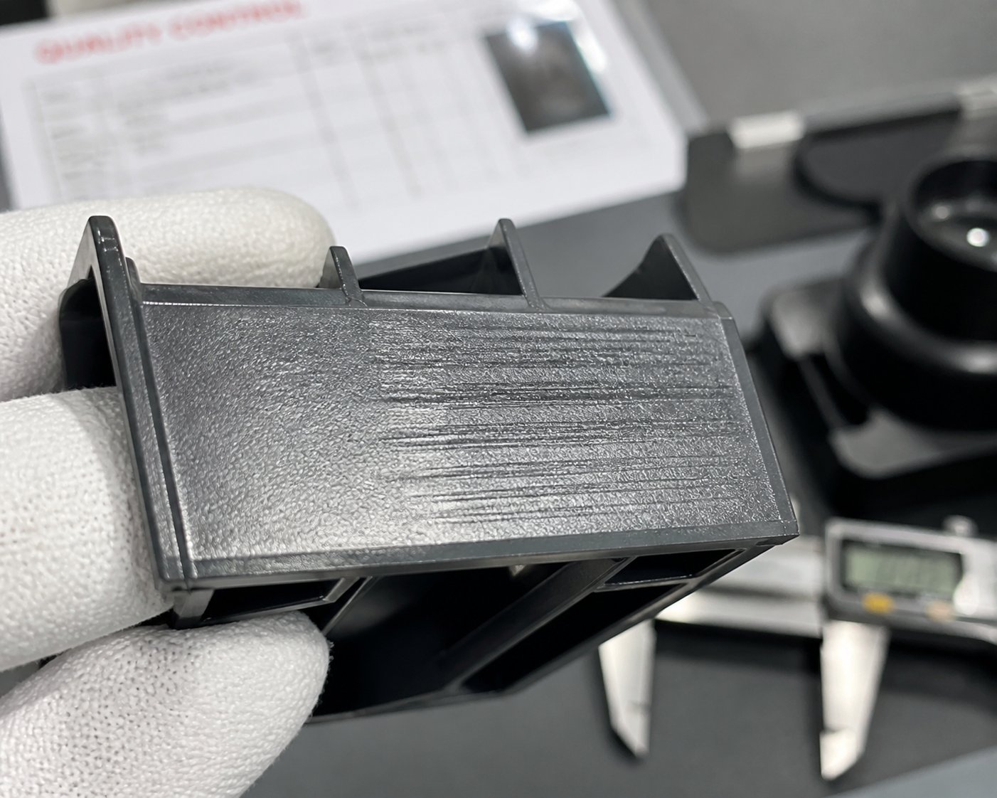
Injection molding drag marks are among the most common - and most frustrating - defects on slide-formed features. They appear as linear scratches, scuffs, or whitened streaks running in the direction of slide retraction. Imagine dragging your fingernail across a soft surface: the resulting groove is essentially what the slide core does to insufficiently drafted plastic as it pulls away laterally during mold opening.
How do they form? When the mold opens and the cam pin begins retracting the slide, the slide core must separate from the solidified plastic surface it shaped. If that surface has adequate taper, a small air gap develops almost immediately, and the slide pulls free with minimal contact. Without enough draft angle, the plastic and steel remain pressed together throughout the retraction stroke. The slide literally scrapes across the part surface, leaving visible scratches, scuffs, or whitened lines that align with the direction of slide travel.
Drag marks aren't just cosmetic. On textured surfaces, they destroy the uniformity of the finish. On sealing surfaces, they introduce micro-channels that compromise leak integrity. On painted or chrome-plated parts, even hairline drag marks telegraph through the secondary finish, creating visible defects that no amount of post-processing can hide.
Drag marks are only one symptom in a family of slide-related defects. Each one links back to a specific draft-related root cause:
- Drag marks (scuffing or scoring): Root cause is draft angle on the slide-formed wall below the minimum required for the resin and surface finish combination. The slide cannot separate cleanly from the part during retraction, and the resulting friction scores the plastic surface. Increasing draft by even 0.5 degrees often eliminates the defect entirely.
- Part sticking on the slide core: The part shrinks onto the slide core during cooling and refuses to release when the slide retracts. Instead of staying in the cavity for ejection, the part travels with the slide - often distorting or breaking in the process. Root cause is a combination of insufficient draft and inadequate mold release, compounded by high-shrinkage resins or overpacking. Tall features or minimal taper are especially prone because the material remains in close contact with the mold surface longer during ejection.
- Flash at slide parting lines: Thin slivers of plastic appear along the boundary where the slide meets the main cavity block. Root cause is worn shut-off surfaces - the angled steel-to-steel contact faces that seal the cavity during injection. As tooling experts have documented, shut-off angles too close to vertical accelerate wear, and thermal expansion from uneven mold temperatures between the slide and cavity halves compounds the problem. Once the shut-off surfaces degrade, gaps open, and plastic fills them. The connection to draft? Insufficient draft on the slide-formed part surface increases retraction force, which accelerates the mechanical wear that degrades those shut-offs in the first place.
- Surface witness lines or mismatch marks: A visible line or step appears where the slide meets the main cavity parting line. While not always a draft problem directly, this defect worsens when slide retraction forces cause micro-displacement of the slide body during injection. Worn gibs and guide rails - degraded faster by the higher forces associated with low-draft features - allow the slide to shift just enough to create a visible mismatch on the part.
The vicious cycle here is worth emphasizing. Insufficient draft increases retraction force. Higher retraction force accelerates wear on cam pins, wear plates, and shut-off surfaces. Worn components allow micro-movement and gap formation. Gaps produce flash. Flash residue scores mating surfaces further. Each cycle degrades the tool a little more, and what started as a marginal draft shortfall becomes a cascading maintenance problem within tens of thousands of shots.
Thread Damage and Core Wear in Screw-Off Molds
Screw-off mechanisms introduce an entirely different failure profile. Instead of linear retraction, the core rotates - and the defects that result from worn or improperly drafted unscrewing cores are uniquely damaging because they compromise the part's functional performance, not just its appearance.
Thread quality in an unscrewing mold depends on the precision of the core's thread profile and the alignment of its rotation. When the core is new and properly aligned, the threads it produces match the design specification within tight tolerances - experienced moldmakers report holding pitch diameter tolerances within 0.004 inches on precision threaded components. Over thousands of cycles, however, two degradation mechanisms attack that precision.
First, the thread crests and flanks on the core itself wear down. Every unscrewing cycle involves steel sliding against solidified plastic under pressure. Even with well-drafted non-threaded sections that minimize gripping forces, the thread flanks experience friction as the core rotates past them. Glass-filled or mineral-filled resins dramatically accelerate this wear because the abrasive fillers act like fine sandpaper against the core steel. Progressively, the thread profile rounds off, lead-in sections lose their sharp definition, and the molded threads begin failing dimensional inspection.
Second - and this is the defect most practitioners overlook - inadequate draft on the non-threaded portions of the unscrewing core amplifies the torque required to unscrew. Picture a bottle cap core: the threads occupy the middle section, but below them sits a smooth cylindrical sealing surface, and above them sits a lead-in bore. If those smooth sections lack proper taper, the part clamps down on them during cooling. When the motor begins rotating the core, it must overcome not just the thread engagement forces but also the friction grip on every non-threaded surface. That extra torque transmits directly through the thread flanks, increasing contact pressure and accelerating wear at the thread crests.
The downstream consequences are tangible:
- Degraded thread quality: Worn cores produce threads with rounded crests, shallow depths, and inconsistent pitch. Parts that once threaded smoothly onto mating components begin to bind, cross-thread, or fail torque specifications.
- Cross-threading risk: As the lead-in section of the core wears, the thread entry becomes less defined. The molded part's thread start loses its guiding taper, making cross-threading during assembly far more likely - a critical failure mode for medical connectors and pressurized fittings.
- Scoring between the core and bushing: Scoring between the unscrewing core and its guide bushing is one of the most common failure modes in automatic unscrewing molds. High heat conditions compound the risk. Using oil-impregnated steel for the core and high-wear-resistant metals for the bushing helps, but if the root cause - excessive torque from inadequate draft - isn't addressed, scoring returns regardless of material upgrades.
- Motor stalling or gear damage: When torque demand exceeds the drive system's capacity, hydraulic motors slip and servo motors fault out, halting production. Repeated over-torque events fatigue gear teeth and strain bearings, leading to catastrophic mechanism failure that can take the mold offline for weeks.
The proactive takeaway is straightforward but consistently underappreciated in academic and encyclopedic resources: optimizing draft on every non-threaded surface of an unscrewing core is one of the highest-return investments in the entire mold. It reduces torque demand, extends core life, preserves thread accuracy, and lowers the frequency of expensive maintenance interventions. A fraction of a degree added to the CAD model during design can defer a $3,000 to $5,000 core replacement by hundreds of thousands of additional shots.
Proactive draft optimization on slides and unscrewing cores doesn't just prevent defects - it fundamentally changes the maintenance economics of the entire mold over its production lifetime.
Recognizing these defects is the diagnostic half of the equation. The other half - maintaining the physical components that form those drafted surfaces cycle after cycle - is what separates molds that run reliably for millions of shots from tools that spend more time on the repair bench than in the press.
Mold Maintenance and Component Longevity in Slide and Screw-Off Tooling
Diagnosing a defect after the fact is valuable. Preventing it from ever appearing is better. And prevention, on the shop floor, comes down to one discipline: maintenance. Molds equipped with slides and unscrewing mechanisms contain dozens of moving, wearing, heat-cycling components that degrade at rates directly influenced by how much draft was designed into the part surfaces they form. A well-drafted mold might run 500,000 shots between major service intervals. A poorly drafted one with aggressive undercuts and minimal taper? You could be pulling that tool for polishing, component swaps, and realignment every 50,000 to 100,000 cycles - burning press time and maintenance labor at a rate that quietly erodes profitability.
The connection between draft and maintenance cost isn't theoretical. It's physics. Lower draft means higher friction during every slide retraction and every unscrewing rotation. Higher friction means more heat, more abrasion, and more mechanical load on every component in the chain - from the cam pin tip all the way back to the plasticizing screw and barrel feeding resin into the cavity.
How Proper Draft Extends Mold and Component Life
Think about what happens inside a slide mechanism over a million cycles. The cam pin slides through its bore in the slide body roughly once per shot in each direction. The slide body glides across its wear plates. The shut-off faces press together under clamping force, then separate as the slide retracts. Every one of those interactions generates friction, and friction generates wear. The question isn't whether these components wear - it's how fast.
Draft is the single biggest variable controlling that rate. When the part surface has adequate taper, the slide core separates from the plastic almost immediately upon retraction. Contact duration is short, retraction force is low, and the mechanical load transmitted through the cam pin, wear plates, and gibs stays well within their design envelope. Reduce that draft by even half a degree on a deep feature, and the slide must drag against the plastic for a longer portion of its stroke. Retraction force spikes, heat builds at the contact interface, and every downstream component absorbs the punishment.
Here's what that looks like in practice across the most wear-prone components:
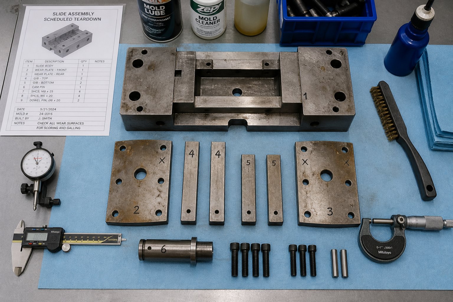
- Cam pins: Higher retraction forces bend and score cam pins at their bearing surfaces. A comprehensive mold maintenance approach includes inspecting pins for light scoring and deep gouges during scheduled teardowns. When draft is marginal, scoring appears sooner and progresses faster, ultimately requiring pin replacement rather than simple polishing.
- Wear plates: These sacrificial bronze or self-lubricating plates are designed to absorb friction - but they have a finite capacity. Excessive slide force from low-draft features compresses and galls wear plates at an accelerated rate. Replacement intervals that should span 200,000 shots can shrink to 50,000 or fewer.
- Shut-off surfaces: The angled steel-to-steel sealing faces between the slide and cavity degrade fastest when retraction forces cause micro-displacement during the closing cycle. Worn shut-offs produce flash, and flash residue further scores the mating surfaces. Proper draft reduces the mechanical load that initiates this cycle.
- Unscrewing cores and bushings: In screw-off molds, inadequate draft on non-threaded core sections increases the torque needed to unscrew the part. That extra torque accelerates wear on the core's thread flanks, scores guide bushings, and fatigues gear teeth in the drive train. Industry maintenance checklists explicitly call out inspection of unscrewing mechanisms, slides, and lifters for wear at every scheduled service interval - and molds with aggressive geometry hit those intervals far sooner.
Material selection compounds the effect. Abrasive glass-filled resins like PA6-GF30 act as fine sandpaper against every steel surface they contact during ejection. On a well-drafted slide core, that contact is brief and the abrasive action is manageable. On a low-draft core, the extended contact duration during retraction multiplies the abrasive wear exponentially. Research into feedscrew wear has documented how glass fibers and mineral fillers create severe abrasion even in areas with limited lubrication - and the same mechanism applies at the mold surface. Larger filler particles with sharper corners wear steel faster than smaller, rounder ones, and the desired physical properties of the molded part typically dictate the filler type, leaving draft optimization as your primary defense.
Proper lubrication is the other critical variable, and it interacts with draft in an important way. Maintenance experts emphasize using high-quality lubricants that meet or exceed manufacturers' recommendations and ensuring contaminants are removed before lubricating. Generous draft reduces the friction load that lubricants must manage, extending both the lubricant's effective life and the component's service interval. When draft is tight, lubricant films break down faster under higher contact pressures, leaving steel-on-steel contact that no maintenance schedule can fully compensate for.
The maintenance schedule implications are stark. A typical mold teardown and restoration takes two to three days on average, or three to five days for heavily worn tools, according to industry practitioners. Molds with well-designed draft on all slide and screw-off surfaces stretch the interval between these teardowns significantly. Cavity and core surfaces stay cleaner longer, texture integrity holds, and the deep ribs and cores that require occasional polishing to ensure proper ejection need that polishing less frequently when draft is doing its job from the start.
Replacement Components and Custom Manufacturing for Injection Machines
Mold wear doesn't happen in isolation. The same resins that abrade slide cores and unscrewing threads also wear the machine components that melt and deliver them. Glass-filled nylon doesn't distinguish between a mold surface and a plasticizing screw flight - it abrades both with equal indifference. And when the injection unit's screw and barrel wear beyond tolerance, the consequences cascade directly into the mold: inconsistent melt temperature, poor shot-to-shot repeatability, and degraded packing pressure control that compounds every draft-related defect discussed in this article.
Extensive analysis of feedscrew wear shows that as the radial clearance between screw flights and barrel wall increases, leakage flow becomes inevitable. Operators see reduced throughput, elevated melt temperatures, and increasing energy consumption. The common rule of thumb considers a flight clearance four times the original tolerance as the replacement threshold - though lower-viscosity resins like PP suffer rate loss sooner than higher-viscosity materials like PE under the same clearance conditions.
What does this have to do with draft and mold quality? Everything. A worn screw produces an inconsistent melt with temperature variations and uneven viscosity. That inconsistent melt fills the cavity differently shot to shot - sometimes overpacking features that then grip the core more aggressively, sometimes underfilling areas that create voids and warping. Features designed with borderline draft become unpredictable: they eject cleanly on one shot and stick on the next. The root cause isn't the mold at all - it's the plasticizing unit feeding it.
Keeping the entire system in specification matters. Barrels should be confirmed within spec annually, or every six months when processing high-wear resins like glass-filled materials. Screw tips need inspection on the same schedule. Experienced screw manufacturers can rebuild worn screws to original tolerances for a fraction of the cost of replacement - often through hardfacing the flight OD and precision grinding back to OEM clearances - extending equipment life through multiple rebuild cycles.
For injection molding factories, machine rebuilders, and maintenance engineers seeking replacement plasticizing components, NANHAIYA's Injection Molding Screw Barrel line offers custom screw barrel manufacturing matched to specific resin families and machine platforms. Whether you're processing abrasive glass-filled compounds that demand bimetallic barrels and hardfaced flights, or running commodity resins on standard equipment, maintaining proper screw-to-barrel clearance is just as critical to part quality as maintaining proper draft in the mold. A well-optimized mold paired with a worn-out plasticizing unit is like a precision instrument fed with inconsistent fuel - the output will never match the tool's potential.
The broader lesson is that mold performance depends on system-level thinking. Draft optimization reduces wear on mold components. Properly maintained slides and unscrewing mechanisms preserve part quality across production runs. And a plasticizing unit held to specification ensures the melt consistency that allows your carefully designed draft angles to function as intended, shot after shot, across millions of cycles.
Putting It All Together for Reliable Part Ejection and Production
Draft angles, side-action slides, and screw-off mechanisms aren't three separate topics you study independently and file away. They're three layers of the same decision - each one building on the last, each carrying its own cost, complexity, and maintenance profile. The entire arc of this article comes down to a single principle that mold draft angle best practices have reinforced for decades, yet too many projects still learn the hard way:
Proper draft is the lowest-cost, highest-impact variable in injection mold design. Every degree of draft you add at the CAD stage is cheaper than every dollar you'll spend on slides, unscrewing mechanisms, defect troubleshooting, and accelerated mold maintenance caused by its absence.
That statement isn't aspirational - it's arithmetic. A part designer spending an extra hour adjusting taper angles in CAD saves the mold builder thousands in slide mechanisms, saves the production floor days of cumulative downtime over the tool's life, and saves the quality team from chasing drag marks, flash, and thread failures that trace back to the same root cause. Whether you're a part designer setting geometry or a mold engineer validating manufacturability, the principles converge on one shared responsibility: get draft right first, and escalate only when the geometry leaves no alternative.
Key Takeaways for Part Designers and Mold Engineers
You've walked through material-specific data, mechanism anatomy, decision frameworks, defect diagnostics, and maintenance realities. Here's the distilled list you can pin above your workstation and reference on every project:
- Apply material-appropriate draft to every surface. Don't default to a generic one degree on everything. PP needs more than ABS. Glass-filled nylon needs more than unfilled. Consult the resin-specific table, match it to your feature type (wall, rib, boss, deep core), and treat the resulting value as a floor, not a ceiling.
- Increase draft for textured and slide-formed features. The one-degree-per-0.025 mm-of-texture-depth guideline applies to every forming surface in the mold - cavity walls, slide cores, and non-threaded sections of unscrewing cores alike. Skipping this adjustment on slide-formed textures is one of the most common oversights in draft angle injection moulding practice, and it produces drag marks that no process adjustment can eliminate.
- Use the escalation framework before committing to complex mold actions. Challenge the geometry first: can a redesign eliminate the undercut entirely? If not, can a linear slide handle it? Only when the feature involves continuous helical threads should you escalate to an unscrewing mechanism. Each step up the ladder adds 15 to 50% in tooling cost, increases maintenance frequency, and - in the case of screw-off actions - extends cycle time by seconds per shot that compound across millions of parts.
- Design shut-off angles and part draft angles together. They share the same physical space in the mold. Treating them as separate decisions leads to geometries that don't close, shut-offs that flash prematurely, and slides that can't retract without dragging across sealing surfaces. A minimum of 3 to 5 degrees on shut-off faces is the widely accepted baseline.
- Monitor and maintain both mold components and plasticizing components. A precision mold paired with a worn screw and barrel produces inconsistent melt that amplifies every draft-related defect. Flight-to-barrel clearance, non-return valve condition, and barrel wear all affect shot-to-shot repeatability - the foundation on which your carefully designed draft angles actually function.
Each of these points represents a fusion draft angle principle - a place where part design, mold engineering, and production maintenance intersect. Miss any one of them, and the others can't fully compensate.
Building a Reliable Injection Molding System from Mold to Machine
It's tempting to think of mold performance as a mold-only problem. But every chapter of this article has pointed toward the same conclusion: the mold is only as good as the system supporting it. Draft optimization reduces ejection forces and extends tool life - but if the plasticizing unit feeding that mold delivers an inconsistent melt with temperature swings and viscosity variation, even generous draft can't prevent sticking, short shots, or dimensional instability.
This is why system-level thinking matters. The same glass-filled nylon that demands 1.5 to 2 degrees of draft on your slide cores also abrades screw flights and barrel liners at an accelerated rate. The same PP that grips cores aggressively due to high crystalline shrinkage also challenges non-return valve sealing as barrel clearances open up over time. Material behavior connects the mold side and the machine side of every production challenge.
Maintaining the plasticizing unit to specification - inspecting screw flight clearances, replacing worn non-return valves, and matching barrel metallurgy to your resin's abrasiveness - is just as critical as polishing slide cores and re-qualifying shut-off surfaces. Suppliers like NANHAIYA offer custom screw barrel manufacturing tailored to specific resin families and machine platforms, giving injection molding factories, machine rebuilders, and maintenance engineers a direct path to restoring plasticizing performance without the lead time and cost of full machine replacement.
The article you've just read covers one keyword cluster - injection molding screw off slide draft - but the real subject is broader: how thoughtful design decisions at the earliest stage cascade through tooling cost, production efficiency, part quality, and long-term maintenance economics. Draft is where that cascade begins. Get it right, document it clearly, and revisit it whenever the resin, texture, or feature geometry changes. Your molds, your press, and your bottom line will all reflect the difference.
FAQs About Injection Molding Draft, Slides, and Screw-Off Mechanisms
1. What is the standard draft angle for injection molding?
The widely accepted baseline is 1 to 2 degrees per side for most features, with a practical rule of thumb of roughly one degree per inch of cavity depth. However, the ideal draft angle depends heavily on the resin family, surface finish, and whether the feature is on the core side or cavity side of the mold. Core-side features typically need 0.5 to 1 degree more draft than cavity-side features because the part shrinks onto the core during cooling, gripping it more aggressively. Glass-filled resins, textured surfaces, and deep ribs all push the requirement higher. For textured surfaces, add approximately one extra degree of draft per 0.025 mm of texture depth on top of the base recommendation.
2. When should I use a side-action slide instead of redesigning with more draft?
A side-action slide becomes necessary when the part geometry includes an external undercut feature — such as a side hole, snap-fit hook, or lateral recess — that cannot be eliminated through redesign or repositioned to align with the mold's line of draw. Before committing to a slide, always evaluate whether a slight geometry change can remove the undercut entirely, since slides add 15 to 30% to tooling costs and introduce wear-prone moving components like cam pins, wear plates, and gibs that require periodic maintenance. If the undercut is functionally non-negotiable and runs perpendicular to the main parting line, a slide is the appropriate solution.
3. What is the difference between a shut-off angle and a draft angle in injection molding?
A draft angle is the taper applied to part surfaces to enable clean ejection from the mold, while a shut-off angle is the angled steel-to-steel contact surface where a slide meets the main cavity block. Shut-off angles seal the cavity during injection to prevent flash, and they must be steeper than part draft angles — typically a minimum of 3 to 5 degrees. These two angles must be designed together because they share the same physical space in the mold. Designing part geometry first and then trying to fit shut-off angles into remaining space often results in geometry that cannot close properly or shut-offs that flash prematurely.
4. How does an unscrewing mold mechanism work for threaded parts?
An unscrewing mold integrates a rotational drive system — rack-and-pinion, hydraulic motor, or electric servo motor — that spins a threaded core out of the molded part before ejection. The core rotates through the exact number of thread revolutions needed to fully disengage the helical threads, replicating the motion of unscrewing a bolt from a nut. Servo-driven systems offer the highest precision and are preferred for medical-grade threaded components like luer connectors. Draft still matters on non-threaded portions of the core, as insufficient taper increases the torque needed to unscrew the part and accelerates wear on thread flanks, bushings, and drive components.
5. How does worn injection screw and barrel affect mold performance and draft-related defects?
A worn plasticizing screw and barrel produce inconsistent melt quality with temperature variations and uneven viscosity. This inconsistency causes shot-to-shot fill variation — sometimes overpacking features that then grip the core more aggressively, sometimes underfilling areas that create voids and warping. Parts designed with borderline draft become unpredictable under these conditions, ejecting cleanly on one shot and sticking on the next. Maintaining proper screw flight-to-barrel clearance is essential. Suppliers like NANHAIYA (nhyscrews.com/products/injection-molding-screw-barrel) offer custom screw barrel manufacturing matched to specific resin families, helping factories restore plasticizing performance and maintain the melt consistency that allows designed draft angles to function reliably.
Written by
Nanhaiya Technical Team
Zhoushan Nanhaiya Plastic Machinery Co., Ltd.
The Nanhaiya technical team supports screw and barrel manufacturing projects through application review, technical communication, custom manufacturing coordination, and production and quality control.
Discuss Your Application
Related Articles
More insights on screw barrel technology and plastics processing.

What Nobody Tells You About Screw Barrel For Plastic Machine Design
Oct 10, 2026
Learn how screw barrel for plastic machine design affects melt quality, throughput, and wear life. Covers geometry, resin matching, troubleshooting, and sourcing.
Read Article
Single Screw Extruder for Sheet: Stop Guessing, Start Specifying
Oct 9, 2026
Learn how to specify a single screw extruder for sheet production. Covers screw geometry, resin-specific processing, troubleshooting, and maintenance best practices.
Read Article
PE Pipe Extruder Machine: What Datasheets Won't Tell You
Oct 9, 2026
Learn how a PE pipe extruder machine works, key specs explained, material grade selection, maintenance tips, and buyer guidance beyond the datasheet.
Read ArticleLooking for something else?
Search by material, symptom or product and jump straight to the relevant page.
These are navigation suggestions based on keyword matching — not a quotation, not a delivery commitment, and not a substitute for engineering review. Final specification is confirmed by our engineers against your drawings and processed material.
Need help with screw barrel selection?
Share your machine model, processed material and application. Our team can help with pricing and technical support.