

Understanding the Injection Molding Screw Barrel
Imagine a component that runs nonstop under extreme heat, intense pressure, and relentless friction — and yet, when it fails, the symptoms rarely point back to it. Mold issues, material defects, machine malfunctions — they all take the blame first. In reality, many of these problems originate in one place: the plasticizing unit. If you work with injection molding, understanding this assembly is not optional. It is foundational.
What Is an Injection Molding Screw Barrel
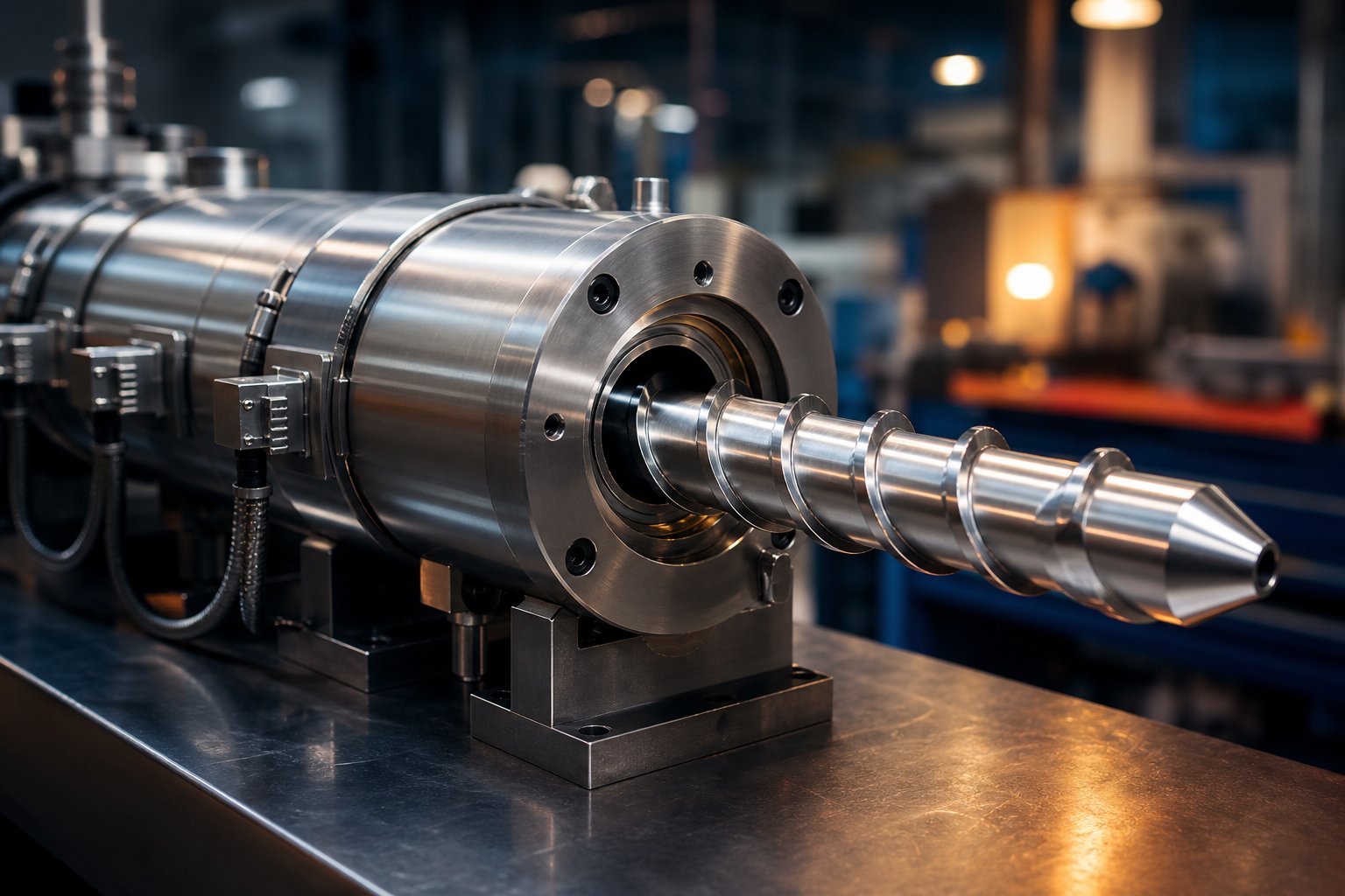
An injection molding screw barrel is the core plasticizing assembly of an injection molding machine, consisting of a hardened cylindrical barrel fitted with external heating bands and a helical-flighted screw that rotates inside it. Together, they melt, homogenize, and inject polymer material into a mold cavity under precisely controlled temperature, pressure, and velocity.
The assembly itself is straightforward in concept. Plastic pellets drop from a hopper into the barrel's feed throat. The injection molding screw then rotates, conveying those pellets forward through progressively hotter zones. Friction between the pellets, the screw flights, and the heated barrel wall generates a combination of conducted and shear-induced heat. This energy transforms solid granules into a uniform molten stream.
What makes this component unique in injection molding — as opposed to a standard extruder — is that the screw serves a dual purpose. It plasticizes the resin during rotation, then acts as a hydraulic plunger during the injection stroke, pushing the accumulated melt shot into the mold. That dual role places extraordinary mechanical and thermal demands on both the screw and the injection molding barrel surrounding it.
Why the Screw Barrel Is the Heart of Plasticization
Every molded part begins as a pool of molten polymer, and the screw barrel is responsible for creating that melt at the correct temperature, viscosity, and homogeneity. When the plasticizing unit performs well, you get consistent shot weights, stable cycle times, and repeatable part dimensions. When it does not, problems cascade quickly — and they are often misdiagnosed.
Consider what happens with a poorly matched screw barrel configuration. Insufficient melting produces unmelted pellets embedded in finished parts. Excessive shear generates burn marks and polymer degradation. Worn clearances between screw flights and the barrel bore allow melt to leak backward, causing shot weight variation and pressure instability. Each of these defects drives up scrap rates, wastes energy, and triggers unplanned downtime that disrupts production schedules.
The real cost goes beyond replacement parts. As industry analysis highlights, downtime expenses far exceed the price of the components themselves. A single poorly specified screw barrel can quietly erode profitability long before anyone suspects it as the root cause.
This article takes a process engineer's approach to the subject. Rather than listing product catalogs, you'll find explanations of the engineering principles that govern how a screw barrel works — its functional zones, critical geometry parameters, screw type selection, wear mechanisms, defect relationships, troubleshooting frameworks, and lifecycle management strategies. The goal is simple: give you the knowledge to diagnose problems early, specify components correctly, and make replacement decisions based on data rather than guesswork.
That understanding begins with the three functional zones inside every plasticizing screw — each with a distinct physics problem to solve and a distinct set of failure modes when incorrectly designed.
The Three Functional Zones of a Screw Barrel Explained
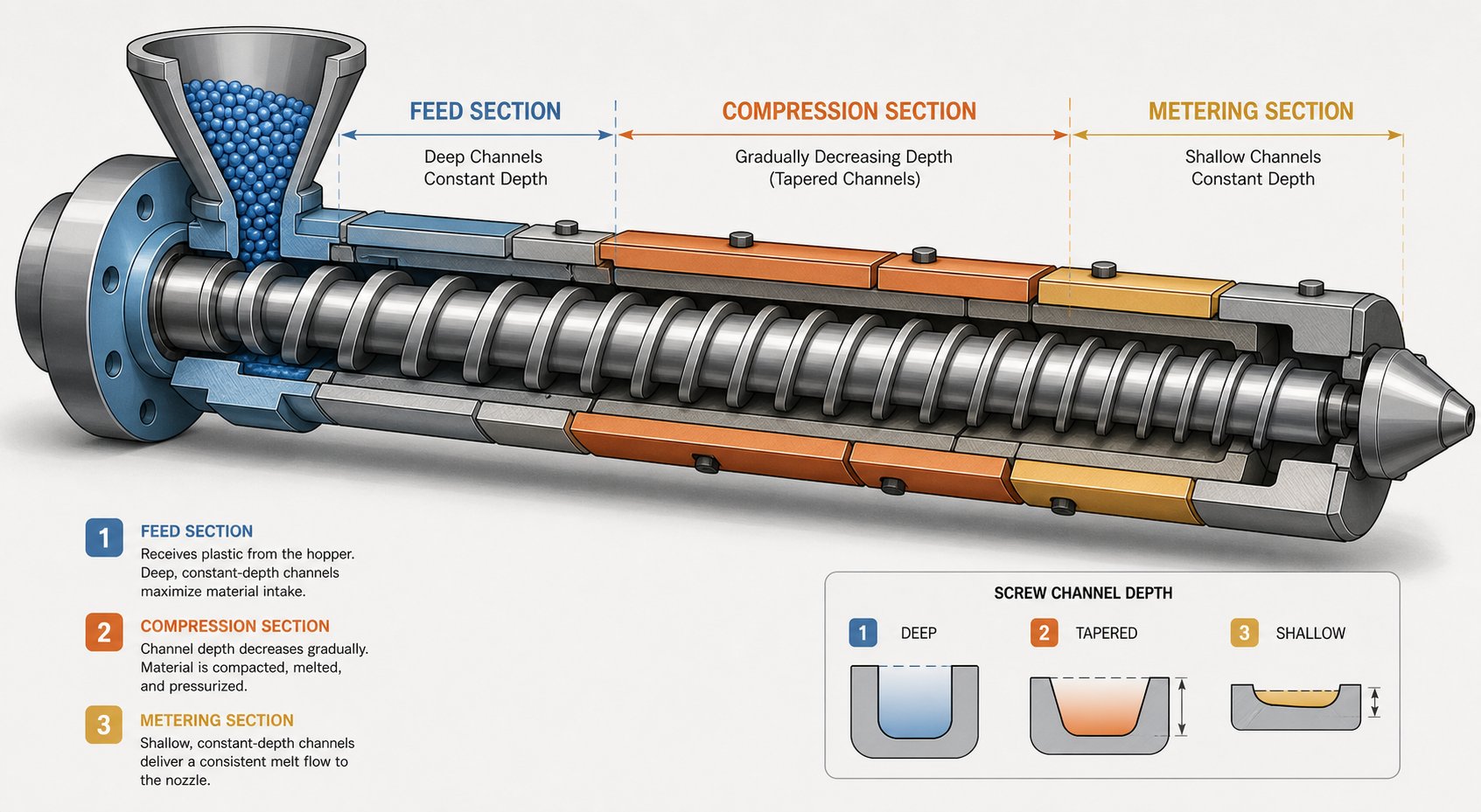
Every plasticizing screw barrel divides its working length into three distinct regions, each solving a different physical problem. Pellets enter as loose solids at room temperature and exit as a pressurized, homogeneous melt ready for injection. The transformation happens progressively — and the physics governing each zone are different enough that a design error in one zone creates symptoms that often appear in another. Understanding these injection molding screw barrel zones is the first step toward accurate diagnosis when something goes wrong on the press.
Feed Zone and Solids Conveying
The screw barrel feed zone is where the process begins — and where it can silently fail. Pellets drop from the hopper through the extruder feed barrel throat and land in the deepest channel section of the screw. The goal here is deceptively simple: move solid granules forward at a consistent rate. The mechanism that achieves this, however, is anything but simple.
Solids conveying depends entirely on a friction differential. The barrel wall must grip the pellets more than the screw root does. When friction against the extruder barrel wall is higher than friction against the screw surface, the rotating flights push material forward like a nut advancing on a bolt. If that differential reverses — say the screw root becomes too rough from wear, or the barrel wall becomes too polished — pellets spin in place without advancing. This condition, called screw slippage, starves downstream zones of material and destabilizes the entire process.
Barrel cooling at the feed throat plays a critical supporting role. Without active cooling, conducted heat from downstream zones migrates backward and softens pellets prematurely. Softened or partially melted granules stick together, bridge across the feed opening, and block material flow. You'll notice this most often during extended cycle times or when processing low-melting-point resins.
Some systems use grooved feed sections — axial or helical grooves machined into a water-cooled barrel liner — to mechanically lock pellets against the barrel wall and dramatically increase conveying force. Grooved feed barrels excel with slippery, high-density polyethylenes and other materials that resist friction-based conveying. The tradeoff is higher pressure generation in the feed zone, which demands a different screw geometry downstream to accommodate the increased throughput.
Compression Zone and Melting Mechanics
As material advances past the feed section, the screw channel depth decreases progressively. This shrinking volume creates compression — forcing the solid bed tightly against the heated barrel wall. A thin melt film forms at the barrel surface, and this is where the real plasticization begins.
The physics here follow what polymer engineers call the Tadmor melting model. Imagine the cross-section of the screw channel in this zone: a solid bed of compacted pellets occupies most of the width, while a growing pool of molten polymer collects on one side, pushed there by the advancing screw flight. The heated barrel melts the top layer of the solid bed into a thin film. The relative motion between barrel and solid bed drags that melt film toward the active flight face, where it joins the melt pool. As more material melts, the solid bed width shrinks and the melt pool grows — until eventually no solid remains.
Research published in Polymers (MDPI) confirms that this contiguous solid melting mechanism accurately describes plasticization behavior in injection molding screws, though the reciprocating motion of the injection screw adds complexity not found in continuous extrusion. The cyclical nature — alternating between static melting (screw stationary) and dynamic melting (screw rotating and retracting) — means the solid bed profile never reaches a true steady state. It stabilizes over multiple cycles instead.
Why does this matter for your process? The compression zone generates more viscous shear heat than any other section of the plasticizing screw barrel. That heat is useful — it supplements conducted heat from barrel heaters and accelerates melting. But excessive compression creates excessive shear, which can degrade heat-sensitive polymers, produce burn marks, or generate uncontrolled melt temperature spikes that compromise part quality downstream.
Metering Zone and Melt Pumping
By the time material reaches the metering zone, it should be fully molten. This final section features a constant, shallow channel depth — and its job is pressure building and homogenization rather than melting.
The metering zone acts as a melt pump, generating the consistent forward pressure needed to push material through the non-return valve and accumulate a precise shot volume ahead of the screw tip. The constant channel geometry creates a predictable drag flow, and back pressure applied during screw recovery further refines melt uniformity by forcing the polymer through additional shear and mixing.
Metering zone length directly affects shot-to-shot consistency. A longer metering section provides more residence time for thermal homogenization and more stable pumping — reducing pressure fluctuations that cause weight variation between shots. However, excessive length increases total residence time, which can be problematic for thermally sensitive resins prone to degradation.
The relationship between metering depth and output is straightforward: shallower channels increase shear rate and improve mixing but reduce volumetric throughput. Deeper channels move more material but sacrifice mixing intensity. Finding the right balance is a core design decision that depends on your specific polymer and part requirements.
| Zone | Primary Function | Typical Length (% of L/D) | Key Design Variables | Common Problems When Incorrectly Sized |
|---|---|---|---|---|
| Feed Zone | Accept pellets and convey solids forward via friction differential | 40–60% | Channel depth, feed throat cooling, barrel surface finish, grooved vs. smooth | Screw slippage, inconsistent feed rate, bridging at hopper throat, output instability |
| Compression Zone | Compact solid bed against barrel wall, generate melt film, transition from solid to melt | 20–30% | Compression ratio, taper rate (gradual vs. rapid), number of turns | Unmelted pellets (too short/low ratio), excessive shear degradation (too aggressive), melt temperature overshoot |
| Metering Zone | Build consistent pressure, homogenize melt temperature and viscosity for injection | 20–30% | Channel depth, zone length, flight clearance to barrel wall | Shot weight variation (too short), thermal degradation from excessive residence time (too long), poor mixing (too deep) |
These three zones work as an integrated system — not independent segments. A feed zone that conveys too aggressively overwhelms a compression zone that cannot melt fast enough. A compression zone with excessive taper creates surging that the metering zone cannot smooth out. And a worn metering section with enlarged clearances loses pumping efficiency, even if the upstream zones function perfectly.
The interplay between zones explains why screw geometry decisions cannot be made in isolation. Each parameter — channel depth, compression ratio, zone length proportion — influences every other. The next logical question becomes: which specific geometric dimensions control these zone behaviors, and how do you select them for a given polymer?
Key Screw Geometry Parameters That Control Plasticization
Three numbers on a screw specification sheet — L/D ratio, flight depth, and compression ratio — determine how effectively every zone performs its job. Change one, and the melting profile, shear history, and output rate all shift. Yet these parameters are frequently copied from machine manuals or supplier defaults without considering whether they suit the actual polymer being processed. The result is a screw that "works" but never truly optimizes melt quality, cycle time, or energy consumption. Here is what each parameter controls and how to use that knowledge as a decision-making framework.
L/D Ratio and Its Effect on Melt Quality
The injection screw L/D ratio — the total flighted length of the screw divided by its diameter — is the single broadest descriptor of a screw's processing capability. A higher ratio means more barrel length available for heat transfer, mixing, and pressure development. A lower ratio means less residence time and a faster, more aggressive plasticization cycle.
Most injection molding screws fall in the 20:1 to 26:1 range. General purpose designs for commodity resins like PE, PP, and PS typically use ratios around 20:1 to 22:1, which provides sufficient melting capacity for polymers that soften readily. Heat-sensitive engineering resins — or applications demanding tight melt temperature uniformity — benefit from longer ratios in the 24:1 to 26:1 range, where the additional length allows gentler, more gradual melting with less reliance on shear-generated heat.
The tradeoff is straightforward. Longer L/D gives you more control over melt homogeneity, but it also increases total residence time inside the injection molding barrel and screw assembly. For thermally stable resins like nylon or polycarbonate, that extra time is harmless. For materials prone to degradation — PVC or certain biopolymers — extended residence can cause yellowing, molecular weight loss, or outright decomposition. So the "best" L/D ratio is not the longest one; it is the one that matches your resin's thermal stability window and your cycle time requirements.
Flight Depth, Pitch, and Helix Angle
While L/D ratio defines the overall screw length, flight depth controls what happens inside the channel at every point along that length. In the feed zone, channels are deep — typically 0.12 to 0.14 times the screw diameter — to maximize the volume of solid pellets conveyed per revolution. In the metering zone, channels are shallow — around 0.05 to 0.07 times the diameter — to intensify shear and improve melt uniformity.
The ratio between these two depths defines the screw barrel compression ratio, which we will examine in detail shortly. But flight depth alone also influences mechanical behavior. Deeper feed channels increase conveying capacity, yet they weaken the screw root cross-section, limiting the torque the screw can safely transmit. Shallower metering channels enhance mixing performance but reduce volumetric output per revolution. Every depth decision involves a capacity-versus-quality tradeoff.
Pitch — the axial distance between adjacent flights — is typically set equal to one screw diameter (1D). This standard pitch produces a helix angle of approximately 17.66 degrees, a value that balances forward conveying efficiency against the shear forces generated as material is dragged along the barrel wall. Increasing the pitch steepens the helix angle, which speeds up material transport but reduces the number of flights along the screw length, cutting into mixing and pressure-building performance. Decreasing the pitch has the opposite effect — more flights, more shear, slower throughput.
For most injection molding applications, the standard 1D pitch works well. Variations are typically reserved for specialty situations: slightly tighter pitch (0.9D) for fast-crystallizing resins like PA and PBT that benefit from increased shear and shorter conveying steps, or wider pitch for powder feedstocks that need aggressive initial transport.
Compression Ratio as a Design Decision
Compression ratio — the feed zone channel depth divided by the metering zone channel depth — is arguably the most consequential single number in screw design. It dictates how aggressively the screw compacts and shears the polymer as it transitions from solid to melt. A ratio of 2.5, for example, means the channel volume shrinks to 40% of its original size between the feed and metering sections. Every pellet passing through that narrowing space is subjected to increasing compressive force and shear intensity.
Different polymer families demand different compression ratios because their melting behavior, viscosity profiles, and thermal sensitivity vary widely:
- Crystalline polymers (PA, PBT, POM): Higher ratios in the 2.5 to 3.5 range. These resins have sharp melting points and transition rapidly from solid to low-viscosity melt, so aggressive compression efficiently collapses the solid bed without generating excessive pressure.
- Amorphous polymers (PS, ABS, PC, PMMA): Moderate ratios in the 2.0 to 2.5 range. Amorphous resins soften gradually over a wide temperature range, so gentler compression prevents excessive shear before the material fully transitions to a flowable state.
- Shear-sensitive materials (PVC-hard, certain bioplastics): Low ratios around 1.8 to 2.0. PVC in particular releases corrosive hydrochloric acid when overheated, so minimal shear-generated heat is essential to avoid both material degradation and barrel corrosion.
What happens when the compression ratio misses the mark? Too high, and the screw generates excessive viscous shear heating that pushes melt temperatures beyond the polymer's safe processing window. You'll see burn marks, degradation streaks, and molecular weight reduction — all of which weaken the finished part. Too low, and the screw fails to fully collapse the solid bed in the compression zone. Unmelted pellets survive into the metering section and appear as visible inclusions or surface defects in molded parts. Melt homogeneity suffers, shot-to-shot consistency drops, and color dispersion becomes uneven.
The right compression ratio is not a universal number — it is a polymer-specific design decision. Always verify target values against resin manufacturer datasheets before specifying or accepting a screw design.
Geometry parameters like L/D, flight depth, and compression ratio define how aggressively or gently a screw processes material. But geometry alone does not tell the full story. A general purpose screw and a barrier screw can share identical L/D ratios and compression ratios, yet deliver dramatically different melt quality — because their flight configurations solve the melting problem in fundamentally different ways.
Screw Types Compared for Injection Molding Applications
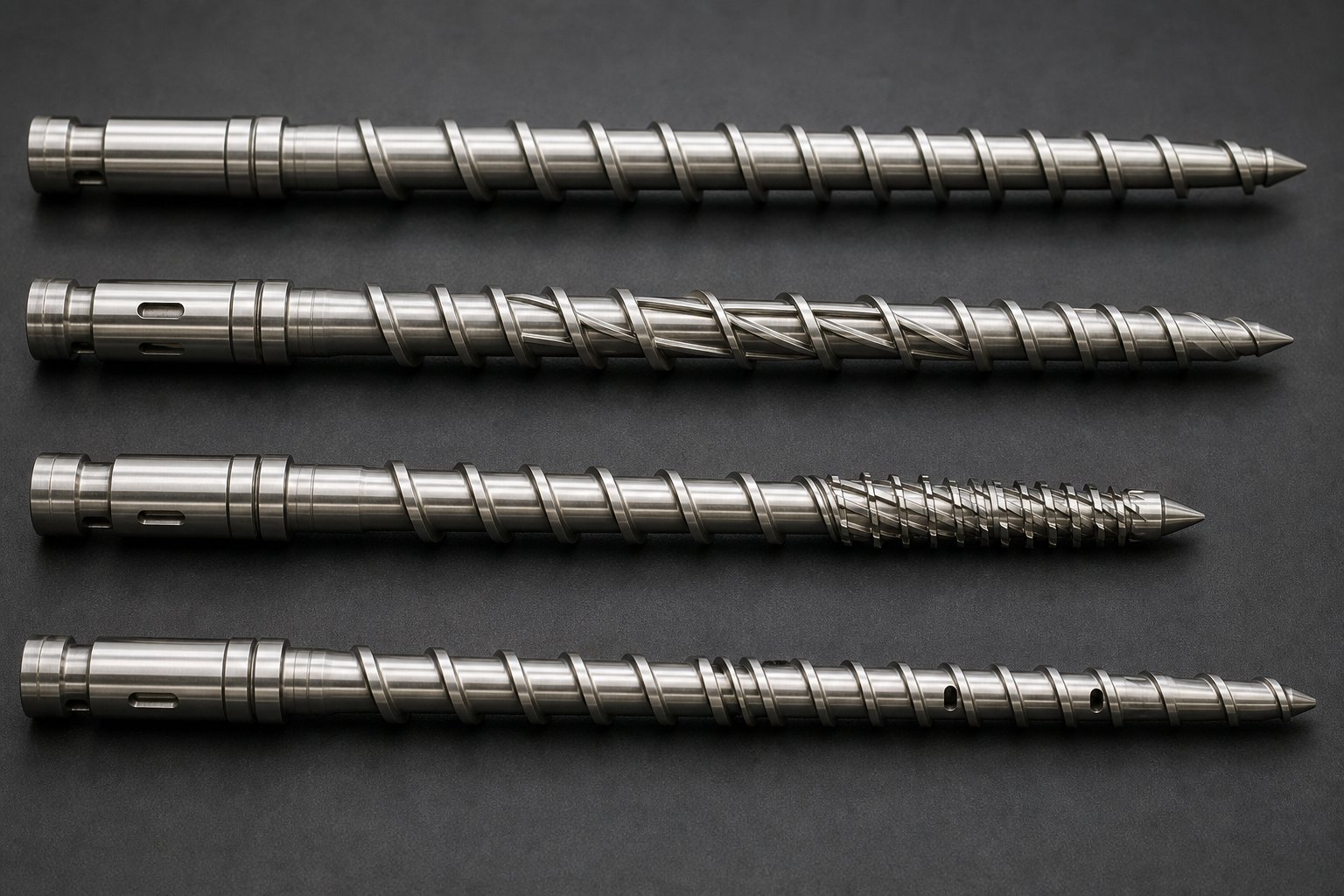
Two screws can share the same diameter, the same L/D ratio, even the same compression ratio — and still produce completely different melt quality. The difference lies in how their flight configurations manage the melting and mixing problems inside the barrel. A general purpose injection screw uses a single continuous flight across three simple zones. A barrier screw introduces a secondary flight that physically separates solid from melt. A mixing screw adds specialized elements that fold and redistribute the polymer. Each design represents a different engineering answer to the same fundamental question: how do you convert solid pellets into a homogeneous, defect-free melt?
Choosing among them is not a matter of picking the most advanced option. It is a matter of matching the screw's capability to your polymer's requirements and your application's quality demands. Here is how each type works, when it excels, and when it falls short.
General Purpose Screws and When They Work
The general purpose (GP) screw is the workhorse of injection molding screws and barrels — and for good reason. Its straightforward three-zone design handles a broad range of commodity resins like polyethylene, polypropylene, and polystyrene without requiring specialized configuration. You load the pellets, set your temperatures, and the screw melts and meters reliably enough for most standard applications.
That versatility is its greatest strength and its defining limitation. A GP screw does everything adequately but nothing optimally. It relies on a single continuous flight to convey, compress, and meter — which means melting capacity is finite and mixing capability is minimal. For a shop running multiple resins on the same machine, this flexibility reduces changeover cost and keeps spare-parts inventory simple.
Where does the GP screw reach its ceiling? When you process engineering-grade resins that demand precise melt uniformity. When you add colorants or fillers that require aggressive dispersion. When production rates push beyond the screw's inherent melting capacity and unmelted particles start appearing in parts. In any of these scenarios, no amount of back pressure adjustment or temperature tweaking will overcome a design limitation built into the screw's geometry. That is the point where specialized designs earn their place.
Barrier Screws, Mixing Screws, and Vented Designs
When a GP screw cannot deliver the melt quality or output stability your application demands, three specialized alternatives address specific processing bottlenecks.
Barrier screws tackle the melting problem directly. A secondary barrier flight runs through the compression zone, creating two separate channels — one for unmelted solids and one for accumulating melt. As polymer melts against the hot barrel wall, it flows over the barrier flight into the melt channel, while unmelted pellets remain trapped in the solids channel until they too liquefy. The result, as research published in Polymers confirms, is that the secondary flight promotes and stabilizes polymer melting by preventing unmelted material from reaching the metering zone. For barrier screw injection molding applications — high-output production of thin-wall packaging, film-grade resins, or crystalline polymers with narrow melting windows — this design delivers measurably better melt consistency and eliminates the unmelted-particle defects that plague overworked GP screws.
Mixing screws solve a different problem: dispersion. When color concentrates streak, glass fibers clump, or additive distribution remains uneven, the issue is not melting capacity but mixing intensity. Dedicated mixing sections — added near the screw tip — come in two functional categories:
- Dispersive mixers (Maddock/fluted): Force melt through narrow clearances at high shear, breaking apart hard agglomerates like pigment clumps and gel particles. Ideal when you need to destroy physical clusters.
- Distributive mixers (pineapple, spiral, pin): Repeatedly split and recombine the melt stream with moderate shear, spreading additives evenly without the aggressive heating of a Maddock section. Better suited for shear-sensitive materials or applications where even blending matters more than agglomerate destruction.
As Plastics Technology explains, pairing a distributive mixer with a barrier screw is often the strongest combination — the barrier handles melting, and the distributive section handles blending without the risk of over-shearing already-melted polymer. This combination is common in demanding applications like engineering-resin compounding or high-precision color-critical parts.
Vented (two-stage) screws address volatile removal. These designs split the screw into two sequential stages separated by a decompression zone. The first stage melts and compresses normally. At the decompression zone, channel depth increases sharply, dropping melt pressure so trapped moisture, air, and volatile byproducts can escape through a barrel vent port. The second stage re-compresses and meters the now-degassed melt for injection.
When would you need a vented design? Primarily when processing hygroscopic resins that absorb atmospheric moisture — nylons, polycarbonates, certain PET grades — without a pre-drying step. They are also valuable for recycled materials that carry residual moisture, volatiles, or contaminants from their post-consumer origin. The tradeoff is a longer overall screw length, higher cost, and a design more specifically tuned to the target resin than a GP alternative.
Choosing the Right Screw Type for Your Resin and Application
The most common specification mistake is approaching screw selection from the product catalog forward — picking a screw type and hoping it fits the resin. The better approach inverts that sequence entirely. Start with the polymer's melting behavior, shear sensitivity, moisture content, and filler loading. Then work backward to the screw configuration that addresses those specific requirements.
Sounds abstract? This comparison table maps each screw type against the practical dimensions that matter on the production floor:
| Dimension | General Purpose | Barrier | Mixing (with mixing section) | Vented (Two-Stage) |
|---|---|---|---|---|
| Suitable Resin Families | PE, PP, PS, ABS, and most commodity resins | Crystalline resins (PA, PBT), high-output polyolefins, film-grade materials | Color-critical applications, filled/compounded resins, masterbatch blending | Hygroscopic resins (PA, PC, PET), recycled materials, volatile-releasing compounds |
| Mixing Capability | Minimal — relies on natural channel shear only | Low on its own; often paired with a mixing section for best results | High — dispersive (Maddock) or distributive (pineapple/pin) depending on section type | Varies — can incorporate mixing elements within either stage |
| Melt Quality Rating | Adequate for standard applications | Excellent — eliminates unmelted particles through forced separation | Good to excellent — depends on mixer type matching the dispersion need | Good — primary advantage is volatile removal, not melt refinement |
| Relative Output Rate | Standard baseline | Higher — barrier design increases usable melting capacity at higher screw speeds | Comparable to GP; mixing section may slightly restrict throughput | Slightly lower — decompression zone reduces effective pumping length |
| Typical Applications | Multi-resin shops, general consumer products, housewares, containers | Thin-wall packaging, high-speed molding, precision parts requiring melt consistency | Automotive color-matched components, filled engineering parts, medical devices with additive uniformity | Un-dried nylon processing, recycled-content molding, PET preforms |
| Relative Cost | Lowest — simplest geometry to manufacture | Medium — secondary flight adds machining complexity | Medium — mixing section adds cost but less than full barrier geometry | Highest — two full stages, longer screw, specialized barrel porting |
Notice the pattern? Each specialized design exists to solve a specific processing bottleneck that a GP screw cannot overcome through process adjustments alone. A barrier screw does not improve color mixing — that requires a mixing section. A mixing section does not remove moisture — that requires venting. And a twin screw and barrel system, while powerful for compounding and reactive processing, introduces a level of mechanical and operational complexity that most standard injection molding applications do not require.
The right screw type is not the most expensive or the most advanced — it is the one whose capabilities directly address the dominant processing challenge posed by your specific resin and application.
This resin-first selection logic applies equally to the materials used to build the screw and barrel themselves. A perfectly specified screw geometry running abrasive glass-filled nylon will lose its performance advantage within months if the flight surfaces and barrel bore cannot resist the wear environment. The question shifts from "which screw design?" to "which materials will keep that design performing over thousands of production hours?"
Screw Barrel Wear Mechanisms and How to Prevent Them
A screw geometry that is perfectly matched to your polymer and application will still degrade over time. Every revolution of the screw, every shot cycle, every abrasive filler particle chips away at the tight clearances that make plasticization work. The critical difference between a well-managed production floor and a reactive one is whether your team can identify what type of wear is occurring, how severe it has become, and which material upgrades will slow it down before defects start reaching finished parts.
Wear in extruder screws and barrels — and in injection molding plasticizing units — follows the same fundamental physics, but the consequences show up differently. In injection molding, even minor clearance increases between the screw flight OD and the barrel bore cause melt to leak backward during screw recovery, destabilizing shot weight and pressure consistency. Understanding the three primary wear mechanisms gives maintenance teams the diagnostic vocabulary to move from symptom chasing to root cause correction.
Adhesive, Abrasive, and Corrosive Wear Mechanisms
Not all wear looks the same — and treating every worn screw or barrel identically leads to repeat failures. Each mechanism leaves a distinct fingerprint on metal surfaces, and recognizing those fingerprints is the first step toward effective screw barrel wear prevention.
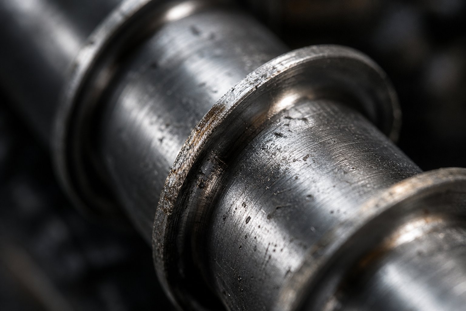
Adhesive wear occurs when the protective melt film between the screw flight and barrel wall breaks down, allowing direct metal-to-metal contact. Under the extreme pressures found in the transition section and metering zone, the two surfaces briefly weld at microscopic contact points, then tear apart as the screw rotates. The result is material transfer from one surface to the other — typically from the softer screw flight to the harder barrel bore, or vice versa. Adhesive wear is often a symptom of larger mechanical problems rather than a standalone issue.
Abrasive wear is the most common mechanism in filled-resin applications. Glass fibers, mineral fillers like calcium carbonate, talc, and even certain pigments act as cutting tools that score and erode metal surfaces. As Plastics Technology notes, the amount of filler present and particle shape strongly influence wear intensity — larger particles with sharper corners cause significantly more damage than smaller, rounder ones. Abrasive wear tends to concentrate in high-pressure areas: the compression zone and the final turns of the metering section, where compressive forces press abrasive particles against flight surfaces with the greatest intensity.
Corrosive wear is a chemical attack rather than a mechanical one. Acidic byproducts generated during processing eat into metal surfaces, weakening them so that mechanical forces remove material far more rapidly than either mechanism would alone. PVC is the most well-known offender — it releases hydrochloric acid at elevated temperatures, creating an extremely aggressive environment inside the extruder screw barrel. Flame-retardant compounds, fluoropolymers, and even standard resins that have been allowed to degrade through excessive residence time also produce corrosive byproducts.
How do you tell which mechanism is dominant in your operation? Each one leaves characteristic evidence that trained eyes — and basic measurement tools — can identify:
- Adhesive wear indicators: Galling marks or smearing visible on screw flight OD; material transfer deposits on barrel bore; typically associated with mechanical misalignment, bent screw shank, gearbox damage, or inadequate lubrication from the melt film.
- Abrasive wear indicators: Uniform scoring or polishing of flight OD surfaces, particularly on the forwarding (pushing) side of the flight; root wear concentrated on the forward face of flights where filler particles accumulate under pressure; progressive loss of flight height measurable with a micrometer.
- Corrosive wear indicators: Pitting or cratering of metal surfaces rather than smooth polishing; generalized surface roughening across the entire barrel bore or screw root — not limited to high-pressure zones; discoloration or chemical deposits visible on metal surfaces after cleaning.
In practice, most real-world wear combines two or even all three mechanisms. A glass-filled nylon application, for example, subjects the screw to severe abrasion from glass fibers while also exposing it to mild corrosive attack from moisture-generated degradation byproducts. Identifying the dominant mechanism guides the most cost-effective material selection for replacement components — a distinction that saves thousands of dollars over a screw's service life.
Measuring Wear and Setting Replacement Thresholds
Knowing wear exists is not enough. You need to quantify it — and that requires consistent measurement methods and clear threshold criteria. Injection barrel wear measurement is one of the most overlooked maintenance disciplines in plastics processing, partly because pulling a screw for inspection means taking the machine out of production. But running without data means running blind until defects force your hand.
Screw measurement starts with thorough cleaning. All solidified resin must be removed from the screw surface before measurements are taken. Davis-Standard's maintenance guidelines emphasize using brass tools and copper gauze only — never steel wire brushes or aggressive abrasives that could damage the surface and falsify readings. Once clean, an OD bar micrometer spans across the flights to measure the outer diameter at multiple points along the screw length, with a tape measure referencing each location. Record readings at every turn or every few turns, paying particular attention to the compression zone and the last several flights of metering — these are the areas where wear concentrates under high-pressure conditions.
Barrel measurement uses internal bore gauges to check the inside diameter at multiple points and rotational positions along the barrel length. You are looking for two specific conditions: ovality (the bore becoming egg-shaped rather than perfectly round) and taper (the bore diameter increasing toward the discharge end where pressures and temperatures are highest). Both conditions increase radial clearance unevenly, which worsens leakage flow and melt quality in ways that uniform wear does not.
When is the wear severe enough to warrant action? General industry guidelines tie replacement thresholds to the screw's nominal diameter, though specific values vary by machine size, resin viscosity, and application tolerance for quality variation. The principle behind these thresholds is based on leakage flow physics: as radial clearance between screw flight OD and barrel bore increases, polymer leaks backward over the flights instead of advancing forward. Output drops, melt temperature rises from the added shear on leaking material, and the operator compensates by increasing screw speed — which accelerates wear further in a self-reinforcing cycle.
A widely cited rule of thumb considers a flight clearance reaching four times the original tolerance as the replacement threshold, but as industry experts point out, this guideline oversimplifies the problem. Higher-viscosity resins like PE tolerate more clearance increase before output loss becomes significant, while lower-viscosity materials like PP show measurable rate loss at smaller clearance increases. Shear-sensitive resins like PVC and polycarbonate may require action well before the four-times threshold because the quality impact from increased shear — not just output loss — becomes unacceptable.
Effective screw barrel troubleshooting starts with baseline dimensional data recorded when the screw and barrel are new or freshly rebuilt. Without that reference point, every subsequent measurement is just a number without context.
Establishing a measurement schedule — and sticking to it — transforms wear from an invisible, gradual process into a predictable maintenance variable. Track screw flight OD and barrel bore diameter at regular intervals, correlate those measurements with shot weight trends and melt temperature data, and you will see the replacement decision point coming months before it arrives as an emergency.
Material Choices That Extend Service Life
Once you know which wear mechanism dominates your application, the next decision is straightforward: select screw and barrel materials engineered to resist that specific attack. Mismatching the metallurgy to the wear environment wastes money — either by over-specifying expensive alloys where they are not needed, or by under-specifying and facing premature replacement.
Nitrided steel is the baseline treatment for standard injection molding barrels and screws. Gas nitriding diffuses nitrogen into the steel surface, creating a hard case layer that resists moderate abrasion and provides reasonable corrosion resistance. For unfilled commodity resins — polyethylene, polypropylene, polystyrene, ABS — nitrided components deliver excellent cost-to-performance ratios and predictable service life. They represent the right choice when the processing environment is not chemically aggressive and filler content is low or absent.
Bimetallic barrel liners step up protection dramatically for demanding applications. A wear-resistant alloy is centrifugally cast inside the barrel bore, creating an inner sleeve with properties far superior to through-hardened steel. The alloy family selected depends entirely on the dominant wear mechanism:
- Iron-based alloys: Provide moderate abrasion resistance at a lower cost than nickel or carbide options. Suitable for lightly filled resins or moderate-volume production where barrel life extension justifies the incremental cost over nitrided steel.
- Nickel-based alloys (e.g., Inconel-type): Excel in corrosive environments — PVC processing, flame-retardant compounds, fluoropolymers, or any application where acidic degradation byproducts attack metal surfaces. Their corrosion resistance far exceeds iron-based alternatives.
- Tungsten-carbide-based alloys: The highest tier of abrasion resistance, designed for heavily glass-filled or mineral-filled compounds where particle abrasion is the primary life-limiting factor. These liners can extend barrel service life significantly compared to nitrided steel under severe abrasive conditions.
Screw flight hardfacing follows a parallel logic. Welded hardfacing alloys — such as Colmonoy 56 or similar nickel-chromium-boron compositions — are applied to the flight OD after the screw is ground to a uniform undercut diameter. This hardfacing process restores wear-resistant surfaces and can be repeated multiple times during a screw's lifespan, provided the base material retains sufficient structural integrity. For extreme abrasion environments, tungsten carbide coatings applied via plasma transfer arc or laser cladding offer the highest flight-life extension.
The key insight here is that material selection is not a standalone decision — it traces directly back to the wear diagnosis performed earlier. An operation running 30% glass-filled nylon needs tungsten-carbide barrel liners and carbide-hardfaced flights. A PVC compounder needs nickel-based alloys to survive the hydrochloric acid environment. A shop processing unfilled ABS may never justify anything beyond well-maintained nitrided steel. Matching the metallurgy to the mechanism is the foundation of cost-effective screw barrel wear prevention.
Wear-resistant materials buy time, but they do not change the physics of plasticization. A worn screw — regardless of its surface treatment — eventually produces defects that no process adjustment can correct. The more valuable question becomes: which specific defects trace back to which specific screw barrel design choices, and how do you close that diagnostic loop before scrap rates climb?
Linking Screw Barrel Design to Molding Defects and Part Quality
Defects on molded parts rarely announce their origin. A burn mark could be a hot runner problem, a venting issue, or a barrel temperature setting — or it could be a screw and barrel design that generates excessive shear no process tweak will ever correct. Silver streaks might point toward material moisture, or they might reveal air entrapment caused by a screw geometry that cannot properly degas the melt. The challenge for process engineers is separating design-driven root causes from parameter-driven symptoms.
This distinction matters because adjusting temperatures, pressures, and speeds to compensate for a hardware mismatch only masks the problem. You end up chasing numbers cycle after cycle while scrap rates hover at unacceptable levels. Effective screw barrel defect troubleshooting starts by asking a different question: is the barrel and screw configuration fundamentally capable of producing the melt quality this application demands?
How Screw Design Causes or Prevents Common Defects
Imagine you are troubleshooting persistent burn marks on thin-wall polycarbonate parts. You have already verified venting, reduced melt temperature, and slowed injection speed — yet the marks persist. The real culprit? A compression ratio of 3.0 on a shear-sensitive amorphous resin that needs 2.0 to 2.3. The screw itself is generating more viscous heating than the barrel heaters can offset, and no downstream adjustment addresses it.
This pattern — where defects originate from mechanical design rather than processing parameters — repeats across a wide range of injection molding plasticization problems. The table below maps the most common design-linked defects to their screw barrel root causes and the engineering solution that eliminates them at the source:
| Defect | Screw Barrel Root Cause | Design Solution |
|---|---|---|
| Burn marks / dark streaks | Excessive shear heating from too-high compression ratio or too-shallow metering channel | Reduce compression ratio; add distributive mixing section to lower peak shear |
| Splay / silver streaks | Moisture or trapped air not removed during plasticization; inadequate melt decompression | Consider vented (two-stage) screw design; verify back pressure and decompression stroke |
| Poor color mixing / streaking | Inadequate dispersive or distributive mixing in the screw design | Add Maddock (dispersive) or pineapple/pin (distributive) mixing section near the screw tip |
| Unmelted pellets in parts | Insufficient L/D ratio or compression ratio too low for the resin's melting requirements | Increase L/D ratio; raise compression ratio within the polymer's safe shear window; consider barrier screw |
| Degradation streaks / yellowing | Excessive residence time in dead spots; poor flight-to-flight transitions trapping stagnant material | Review flight geometry and radius transitions; eliminate abrupt channel depth changes; shorten metering for sensitive resins |
| Shot weight variation | Worn clearances allowing melt leakage over flights; inconsistent metering zone pumping | Replace worn screw and barrel to restore designed clearances; extend metering zone length for stability |
| Flow lines / surface imperfections | Melt temperature non-uniformity from poor homogenization in metering zone | Increase metering zone length; add mixing elements; verify barrel heater function zone-by-zone |
Notice how several defects share overlapping root causes. Burn marks and degradation streaks both involve excessive thermal exposure — but from different mechanisms (shear intensity versus residence time). Similarly, unmelted pellets and poor color mixing both reflect inadequate processing intensity, yet they demand different solutions: one needs more compression energy, the other needs mixing geometry. The diagnostic value comes from distinguishing which thermal or mechanical pathway is producing the visible symptom.
Matching Screw Barrel Configuration to Processing Goals
Rather than selecting a screw and barrel from a catalog and hoping it performs, a resin-first decision framework produces consistently better outcomes. Here is how it works in practice:
Step 1: Define the polymer's constraints. Every resin has a melt temperature window — the range between adequate flow and the onset of degradation. Shear-sensitive materials like PVC or PMMA have narrow windows. Thermally stable polyolefins have wide ones. This window immediately constrains how aggressively the screw can shear the material, which sets boundaries on compression ratio and metering depth.
Step 2: Assess filler content and additive requirements. Glass fibers demand abrasion-resistant metallurgy and influence compression zone design. Colorants or additives that need uniform dispersion dictate mixing section requirements. Hygroscopic resins or recycled feedstock with volatile content point toward vented designs.
Step 3: Work backward to geometry. With constraints defined, you select the L/D ratio, compression ratio, and mixing elements that satisfy all requirements simultaneously. A 30% glass-filled PA6 processed for automotive structural parts, for example, needs a compression ratio around 2.5 to 3.0, a barrier flight to ensure complete melting at high screw speeds, abrasion-resistant hardfacing, and possibly a dispersive mixer to break apart fiber bundles — all driven by the resin's behavior, not by a standard catalog option.
This approach inverts the typical purchasing process. Instead of asking "what screws do you have in stock?" you ask "what does my polymer need to produce defect-free parts at target cycle time?" The screw design then traces directly to material behavior verified through testing — not assumption.
Every screw barrel specification should trace back to a specific polymer processing requirement. If you cannot name the resin behavior that justifies a design choice, that choice is a guess — and guesses produce scrap.
This resin-first logic extends beyond geometry selection into the metallurgical decisions that determine how long your optimized design will maintain its performance. The same glass-filled nylon that dictates barrier geometry and high compression also demands materials capable of surviving tens of thousands of abrasive cycles — which is precisely where bimetallic technology enters the equation.
Bimetallic Barrel and Screw Technology Explained
You have likely seen the term "bimetallic" on screw barrel quotes — often listed as a premium option with a higher price tag and a vague promise of longer life. But what does bimetallic actually mean at a metallurgical level? Why does it outperform standard nitrided steel in certain applications, and when does the extra investment fail to pay for itself? The answers lie in how these components are manufactured and which alloy families address which wear environments.
What Makes a Barrel or Screw Bimetallic
The word itself tells you the core concept: two metals. A structural base steel provides mechanical strength — carrying injection pressures, supporting barrel mounting loads, and resisting fatigue. A second, metallurgically bonded alloy layer lines the working surfaces that actually contact the polymer melt. Each component reaches that two-metal structure through a different manufacturing process.
For the extrusion barrel or injection barrel, the process is centrifugal casting. A pre-bored steel cylinder is loaded with alloy powder, heated in a furnace until the alloy melts, then spun at high speed. Centrifugal force drives the molten alloy outward against the barrel bore wall, producing a dense, uniform liner typically 1.6 mm (0.063 in.) thick at ideal specification — though some manufacturers cast liners in the 2.0 to 3.0 mm range for extended reboring capability. The spinning action eliminates porosity and ensures a metallurgical bond to the backing steel rather than a mechanical fit that could delaminate under thermal cycling.
For the screw, bimetallic construction means hardfacing the flight surfaces — the outermost edges that ride against the barrel bore and experience the most intense abrasive contact. Plasma transferred arc (PTA) welding deposits a wear-resistant alloy directly onto the screw flight OD, building a hardfacing layer of approximately 1.0 to 1.5 mm that is then precision-ground back to final diameter. This creates a sacrificial wear surface far harder and more abrasion-resistant than the underlying screw steel.
The alloy chemistry selected for each component depends entirely on the wear mechanism you identified in your application. Three broad alloy families cover the spectrum of processing environments:
- Iron-based alloys (Fe+Ni+Cr+B): The general-purpose bimetallic grade. Strong hardness (HRC 58-62) and good abrasion resistance make them suitable for moderately filled resins and applications where corrosion is not the dominant threat. Lower cost than nickel or carbide alternatives.
- Nickel-based alloys (Ni+Cr+Co+B): Engineered for corrosion resistance. These compositions resist the hydrochloric acid released by PVC, the acidic byproducts of flame-retardant compounds, and the chemical attack from fluoropolymers. They trade some abrasion resistance for chemical durability — the right tradeoff when corrosion is what kills your barrel.
- Tungsten-carbide-based alloys (Ni+WC+Cr+B): The premium tier for extreme abrasion. Hard carbide particles suspended in a nickel-chromium matrix deliver the highest anti-wear performance even though bulk hardness numbers may appear lower than iron-based grades. The embedded carbides do the work against glass fibers and mineral fillers — not matrix hardness alone. These alloys handle the most aggressive filled compounds: 30%+ glass-fiber nylon, heavily mineral-loaded polyolefins, and recycled streams containing abrasive contaminants.
A critical detail that many processors overlook: the screw alloy and barrel alloy must be compatible. Certain hardfacing materials used on screws can cause accelerated wear when paired with specific barrel liner alloys — a phenomenon that produces catastrophic results rather than extended life. This is why specifying an extruder screw and barrel as a matched system, rather than sourcing components independently from different suppliers, protects against incompatibility failures.
Performance Advantages and ROI Considerations
The performance case for a bimetallic screw barrel is straightforward in abrasive or corrosive environments. A nitrided barrel for injection molding applications relies on a thin diffused case — typically 0.4 to 0.7 mm deep — that provides excellent hardness but limited total wear material. Once abrasive fillers cut through that case, they reach softer core steel that erodes rapidly. In contrast, a bimetallic liner offers 2.0 to 3.0 mm of wear-resistant alloy — roughly four to six times the protective depth of nitriding.
Industry data from bimetallic barrel manufacturers indicates service life improvements of 3 to 5 times compared to nitrided components in filled-compound applications. On unfilled HDPE or PP, a nitrided barrel might deliver 12,000 to 20,000 hours of service. The same barrel in bimetallic construction can reach 30,000 to 50,000+ hours. For filled PP or glass-reinforced nylon, the contrast is even more dramatic: nitrided components may last only 3,000 to 6,000 hours while bimetallic equivalents run 15,000 to 25,000 hours before reaching replacement thresholds.
The ROI framework for evaluating bimetallic investment goes beyond the invoice price. Consider the total cost across a production period — say three to five years — and compare the cumulative expense of each approach:
- Replacement frequency: A nitrided barrel replaced three or four times over five years accumulates purchase costs, installation labor, and alignment verification expenses at each change. A single bimetallic barrel covering the same period eliminates those repeated costs.
- Scrap rates during wear plateau: As any barrel wears, clearances open and melt quality degrades gradually. Bimetallic components maintain their designed clearances longer, keeping scrap rates at baseline levels for a greater percentage of their total service life.
- Unplanned downtime reduction: Every unscheduled barrel change means lost production hours. Bimetallic longevity converts emergency replacements into planned maintenance events that fit within scheduled shutdown windows.
- Energy consumption: Worn clearances force operators to increase screw speed to maintain output — consuming more drive energy per kilogram of processed material. Longer-lasting clearances mean lower specific energy consumption over the barrel's working life.
When does bimetallic investment make economic sense, and when is standard nitrided steel the smarter choice? The decision hinges on several application-specific factors:
- Filler content above 10-15% glass fiber or mineral loading — bimetallic strongly justified
- Processing PVC, flame-retardant compounds, or fluoropolymers — corrosion-resistant bimetallic required
- Running recycled or post-consumer feedstock with contaminants — bimetallic protects against unpredictable abrasion
- High-volume production running 24/7 where downtime cost is extreme — bimetallic ROI accelerates
- Short production runs with frequent resin changes on unfilled commodity resins — nitrided steel suffices at lower cost
- Low annual machine utilization where total cycles remain modest — nitrided components may never reach their wear limit
- Budget constraints where the dominant resin is clean, unfilled polyolefin — nitrided delivers adequate service without overspending
The harder question is not whether to go bimetallic — it is which alloy combination to specify for your particular feedstock. That decision requires the kind of technical consultation where a supplier evaluates your resin, filler loading, processing temperatures, and production volume before recommending a specific metallurgy. Manufacturers like NANHAIYA, who offer both standard nitrided and bimetallic screw barrel configurations with custom engineering for specific wear environments, exemplify this consultative approach — providing the metallurgical expertise to match alloy grade to application rather than defaulting to a one-size-fits-all catalog option.
Selecting the right bimetallic grade is a purchasing decision. But keeping that investment performing at its designed capability over thousands of production hours requires something else entirely — a systematic approach to diagnosing performance problems before they become part defects. That diagnostic framework is where most maintenance teams need the most practical support.
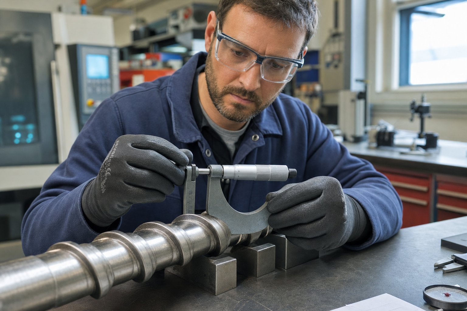
Troubleshooting Common Screw Barrel Performance Problems
Your injection screw and barrel might be correctly specified, built from the right alloys, and installed to exact tolerances — and still produce problems six months into production. Wear progresses. Process conditions drift. Resins change. Heater bands fail silently. The difference between a shop that catches these issues early and one that discovers them through customer complaints comes down to a structured diagnostic approach — a screw barrel troubleshooting guide that separates hardware root causes from process parameter errors before anyone starts turning dials.
Diagnosing Poor Plasticization and Melt Inconsistency
When plasticization degrades, the symptoms are frustratingly nonspecific. Shot weight drifts between cycles. Melt temperature readings swing by several degrees. Visible unmelts — small solid particles embedded in otherwise molten parts — appear sporadically. An operator's instinct is to increase barrel temperatures or raise back pressure, and sometimes those adjustments help temporarily. But if the root cause is mechanical rather than thermal, process tweaks only mask a problem that will continue worsening.
Start your diagnosis by isolating what changed. If melt quality was stable for thousands of hours and then gradually deteriorated, progressive screw or barrel wear is the most likely explanation. Increased radial clearance between the injection screw flights and the barrel bore allows melt to leak backward over the flights during recovery, reducing the effective pumping capacity of the metering zone. You'll notice it first as shot weight variation — typically within a range of a few tenths of a gram — and increased screw recovery time as the plasticizing unit works harder to accumulate the same shot volume.
Walk through these checks systematically:
- Screw wear clearance: If the screw has not been pulled and measured recently, schedule a measurement. Compare flight OD readings against your baseline data. Pay close attention to the compression zone and the final metering flights, where wear concentrates under high-pressure conditions.
- Barrel heater function: Verify every heater band zone individually. A failed heater band in the transition zone — where the highest melting energy input occurs — will produce unmelts that no amount of temperature increase in adjacent zones can compensate for. Check actual versus setpoint temperatures using an independent thermocouple, not just the controller readout. As John Bozzelli of Injection Molding Solutions emphasizes, a zone that "should" be stable can drift or overshoot by several degrees, especially on older equipment.
- Back pressure settings: Insufficient back pressure allows air to remain trapped in the melt and reduces mixing intensity. Too much back pressure extends recovery time and adds unnecessary shear heat. Verify that the setting has not been changed from the validated process — a common occurrence during shift changeovers.
- Screw design versus current resin: Has the resin changed since the screw was specified? Switching from an unfilled PP to a glass-filled PA on the same general purpose screw introduces a mismatch that no parameter adjustment resolves. The screw lacks the melting capacity, mixing capability, and wear resistance the new material demands.
If clearance measurements show wear within acceptable limits, heater bands all function correctly, and the screw matches the resin, the problem likely lives in process parameters — back pressure, screw RPM, or barrel temperature profile. But confirming the hardware is sound before chasing process variables saves hours of unproductive adjustment.
Solving Black Specks, Degradation, and Screw Slippage
Some problems announce themselves unmistakably. Black specks on a white or clear part demand immediate attention. Degradation streaks through a transparent polycarbonate housing trigger customer rejections. Injection molding screw slippage — where the screw rotates but material refuses to advance — shuts production down entirely. Each has a distinct set of causes, and confusing one for another leads to wasted time and incorrect corrective actions.
Black specks are, at their core, carbonized polymer. The question is where the carbonization happened. Three primary sources account for the vast majority of cases:
- Dead spots in screw flights: Worn flight surfaces create small pockets where resin stagnates, overheats, and eventually carbonizes. The carbonized material clings to the metal surface until the flow finally dislodges it — sending a flake of char downstream into the melt stream. As injection molding defect analysis confirms, when purging reduces specks only temporarily, residue lodged deep inside the screw flights or around the check ring is the likely source. A screw pull and physical cleaning become necessary.
- Worn check ring: A non-return valve that seals inconsistently allows melt to flow backward during injection, trapping small pockets of resin that cycle repeatedly between melted and pressurized states. That material eventually degrades, carbonizes, and breaks loose as dark specks or flakes. If you notice that specks appear most prominently during startup or after brief production pauses, check ring condition is the first thing to investigate.
- Overheated barrel zones: A thermocouple reading that drifts just 5 to 10 degrees above setpoint in a rear zone can carbonize residual resin over extended runs — especially with heat-sensitive materials like PC, POM, or flame-retardant ABS. The plasticizing process demands stable temperature control; even small drifts produce degradation products that accumulate faster than the melt stream can flush them out.
Degradation streaks share some causes with black specks but manifest differently. Rather than discrete particles, you see discolored flow lines or yellowed regions within the part — evidence that the polymer itself has lost molecular weight or undergone chemical changes during plasticization. The root causes typically involve excessive residence time (material sits in hot zones too long between shots), dead spots in the screw geometry where stagnant melt pools form, or barrel temperatures that exceed the polymer's thermal stability limit.
A simple diagnostic step: reduce shot delay time or increase shot size to reduce residence time. If the streaks diminish, thermal exposure duration is the driver. If they persist, the geometry of the screw — particularly abrupt channel depth transitions or worn areas that create stagnation zones — is likely trapping and degrading material regardless of cycle timing.
Injection molding screw slippage is a different category of failure entirely. The screw rotates at its set RPM, the motor draws normal current, but material does not advance. Recovery time stretches indefinitely. The barrel starves of material, and parts come out short or completely unfilled.
Screw slippage means the friction differential that drives solids conveying has collapsed. Recall from the feed zone discussion: pellets advance because barrel wall friction exceeds screw root friction. When that balance reverses, material spins in place. Three conditions cause this reversal most frequently:
- Inadequate feed throat cooling: Heat migrating backward from the transition zone softens pellets in the feed area, reducing their ability to grip the barrel wall. Plugged or undersized cooling lines at the feed throat are a common and easily overlooked culprit. Industry experts note that roughly 80% of processes have issues with feed-throat temperature control — making it the single most statistically likely cause of feeding problems.
- Polished screw root in the feed zone: Over thousands of hours, the screw root surface in the feed section can become polished smooth — either from normal wear or from abrasive resin particles. A smooth root grips pellets more effectively, which sounds beneficial but actually destroys the friction differential. Pellets rotate with the screw instead of advancing along it. Restoring a controlled surface roughness on the feed section root — through bead blasting or controlled texturing — often resolves chronic slippage that no temperature adjustment corrects.
- Incorrect resin form factor: Switching from standard pellets to regrind with irregular particle shapes, powdered resin, or micro-pellets changes the bulk friction characteristics of the feedstock. The screw's feed geometry was designed for a specific pellet size and shape — significantly different form factors disrupt conveying behavior. Pre-blending regrind at controlled ratios with virgin pellets, or adjusting the feed throat temperature profile, often restores stable conveying.
A critical distinction separates slippage from bridging, though both present as material starvation. Bridging blocks the feed throat physically — you can see compacted or fused pellets obstructing the opening. Slippage leaves the feed throat clear; material simply fails to move forward once inside the screw channel. If you clear the hopper and see no blockage at the throat, slippage is your diagnosis, and feed throat cooling plus screw root condition become the investigation targets.
A Systematic Troubleshooting Sequence for Screw Barrel Issues
When production problems point toward the plasticizing unit, resist the urge to change multiple variables simultaneously. A structured sequence isolates root causes far more efficiently than scattershot adjustments — and it prevents the common trap of "fixing" a symptom by introducing a new problem elsewhere.
Effective troubleshooting starts with baseline measurements of screw and barrel dimensions before adjusting processing parameters. Without knowing the mechanical condition of your plasticizing components, every process change is an uninformed guess.
Follow this diagnostic sequence when screw barrel performance degrades:
- Record current process data before changing anything. Document barrel zone temperatures (actual vs. setpoint), screw RPM, back pressure, recovery time, cushion position, and shot weight over at least 10 consecutive cycles. This snapshot becomes your diagnostic baseline.
- Verify all barrel heater bands are functioning. Use an infrared thermometer or thermal camera to confirm that every zone is producing heat. A failed band in the transition zone is one of the most common — and most overlooked — causes of incomplete melting and melt temperature instability.
- Check thermocouple accuracy. Compare each zone's controller reading against an independent thermocouple measurement. Drift of more than 5 degrees between the two readings indicates a thermocouple that needs replacement — a root cause that masquerades as a temperature profile problem.
- Inspect feed throat cooling. Confirm coolant flow through the feed throat water jacket. Plugged or scaled cooling lines cause gradual temperature creep that produces bridging or slippage symptoms that worsen over weeks and are easily attributed to other factors.
- Assess the non-return (check) valve. Perform a cushion consistency test: run 10 shots and record the cushion position. Variation exceeding 1 to 2 mm suggests a leaking check ring that allows melt backflow during injection — degrading shot weight repeatability and potentially contributing to stagnation and black speck formation.
- Measure screw flight OD and barrel bore diameter. Pull the screw if symptoms persist after all process checks pass. Compare measurements against baseline data or nominal specifications. Clearance increases concentrated in the compression and metering zones confirm progressive wear as the root cause.
- Evaluate whether the screw design matches the current resin. If the material being processed has changed — different polymer family, different filler content, different form factor — since the screw was specified, reassess the match between screw geometry and polymer requirements before investing in repair or replacement of the existing design.
- Make one process adjustment at a time and re-measure. If the hardware checks clear and the screw design is appropriate, adjust a single process variable — back pressure, screw RPM, or a specific barrel zone temperature — then run a minimum of 20 cycles and re-evaluate. Document the change and the result. Sequential adjustments prevent the confounding effects of simultaneous changes.
This sequence follows a deliberate logic: confirm hardware condition first, process parameters second. Most persistent plasticization problems trace back to mechanical wear or equipment malfunction rather than incorrect settings — yet most troubleshooting efforts begin (and stall) at the controller screen. Reversing that order catches the real root cause faster and avoids the frustration of optimizing parameters on a mechanically compromised system.
Effective troubleshooting extends the useful life of your screw and barrel — but every component eventually reaches the point where repair is no longer economical and replacement becomes the sound business decision. Knowing how to manage that full lifecycle, from initial selection through final replacement, turns reactive maintenance into a planned, budgetable process.
Screw Barrel Lifecycle Management and Smart Replacement Decisions
A screw barrel does not fail in an instant. It degrades across thousands of production hours — slowly, measurably, and predictably if you are paying attention. The shops that budget for replacement before it becomes an emergency share one trait: they manage the full lifecycle as a planned process rather than reacting to crises. From initial selection through final decommissioning, every stage of ownership presents decisions that compound over time. Get the early decisions right, and you extend service life by thousands of hours. Get them wrong, and you inherit problems that no amount of injection molding screw barrel maintenance can solve.
Selection and Installation Best Practices
The lifecycle begins before the component ever touches a production machine. Selection errors — choosing the wrong geometry, the wrong alloy, or an incompatible dimensional specification — lock in performance limitations that persist until you replace the part entirely. Here is the decision framework distilled from everything covered in this article:
Identify resin requirements first. What is the polymer's melt temperature window? Is it shear-sensitive? Does it contain abrasive fillers or release corrosive byproducts? These answers drive compression ratio, L/D, and mixing element decisions — not the other way around.
Determine the dominant wear environment. Glass-filled compounds demand tungsten-carbide-based bimetallic liners. PVC or flame-retardant resins need nickel-based corrosion-resistant alloys. Unfilled commodity resins run well on nitrided steel. Matching metallurgy to mechanism prevents both overspending and premature failure.
Select geometry and materials simultaneously. A barrier screw with distributive mixing serves glass-filled nylon far better than a general purpose design — but only if the flight hardfacing also resists the glass fiber abrasion. Geometry and metallurgy must align with the same processing reality.
Verify dimensional compatibility with the machine. Confirm bore diameter, overall length, mounting flange dimensions, nozzle seat geometry, and drive spline or key specifications against the machine manufacturer's drawings. Even 0.1 mm of mismatch at a critical interface creates alignment issues that accelerate wear from day one.
Installation itself demands equal discipline. Proper installation practices — following manufacturer guidelines for torquing barrel bolts evenly, using precision alignment jigs, and verifying concentricity with dial indicators or laser tools — prevent the mechanical stress and uneven contact that cause premature wear. Thermal expansion during initial heat-up can shift alignment, so re-checking bolt torque after the first full temperature cycle is a best practice that many shops overlook.
Initial break-in also matters. Running the first several hundred cycles at reduced screw speed and moderate back pressure allows mating surfaces to conform without generating the aggressive metal-to-metal contact that causes adhesive wear on fresh components. Think of it like breaking in an engine — controlled, gentle operation early on pays dividends in long-term durability.
Monitoring, Maintenance, and Knowing When to Replace
Once installed, your screws and barrels enter a long performance plateau — hundreds of thousands of cycles where melt quality remains stable and dimensional clearances stay within specification. The goal of injection molding screw barrel maintenance is to monitor that plateau, detect when it begins to decline, and schedule replacement during planned downtime rather than reacting to defects that have already reached customer parts.
Shot weight trending is the simplest and most powerful early-warning tool available. Record shot weight across 20 to 50 consecutive cycles at regular intervals — weekly for high-utilization machines, monthly for lower-volume equipment. As clearances between screw flights and barrel bore increase from wear, shot weight variation grows before any visible defect appears in parts. A steady increase in the standard deviation of shot weight data signals that the metering zone is losing pumping efficiency — the earliest measurable symptom of progressive wear.
The economic decision point for replacement is not when the screw barrel stops working — it is when the cumulative cost of continuing to run exceeds the cost of replacing. That calculation includes rising scrap rates from deteriorating melt quality, increasing energy consumption as operators raise screw speed to compensate for lost output, extended cycle times from longer recovery, and the risk cost of an unplanned failure shutting down production entirely.
As industry maintenance specialists emphasize, when repair and maintenance costs exceed the cost of replacement — factoring in the downtime each repair event requires — the financially sound decision is to invest in a new component rather than extending a worn one. Waiting until failure forces your hand means paying emergency pricing, accepting whatever lead time the supplier imposes, and absorbing lost production that could have been avoided.
A comprehensive screw barrel replacement guide should anchor around these lifecycle milestones and corresponding actions:
- Installation (0 hours): Record baseline measurements of screw flight OD and barrel bore diameter at multiple points. Document the screw design parameters, alloy specifications, and machine compatibility details for future reference.
- Break-in period (0–500 hours): Run at moderate conditions. Re-torque barrel bolts after first thermal cycle. Establish baseline shot weight data and recovery time benchmarks.
- Routine monitoring (500–5,000+ hours): Conduct periodic shot weight trending. Check barrel heater function and thermocouple accuracy quarterly. Inspect feed throat cooling system for scale buildup or reduced flow.
- First measurement interval (manufacturer-recommended or at first sign of shot weight drift): Pull the screw and measure flight OD at all zones. Bore-gauge the barrel for ovality and taper. Compare against baseline data and calculate clearance increase.
- Wear plateau management (ongoing): Continue periodic measurement. Track the rate of clearance increase over time. Project when replacement thresholds will be reached based on the observed wear rate and production schedule.
- Replacement decision point: When clearance measurements approach threshold limits, or when scrap rate and energy data confirm that continued operation costs more than replacement, order the replacement component and schedule installation during a planned maintenance window.
- End-of-life disposition: Evaluate whether the worn screw can be rebuilt (re-hardfaced and reground) economically, or whether full replacement is more cost-effective given the extent of wear and the remaining structural integrity of the base material.
This structured approach transforms replacement from a reactive emergency into a predictable budget line item — one you can plan for, negotiate pricing on, and execute without disrupting production schedules.
Partnering with the Right Screw Barrel Supplier
Every decision in this lifecycle — from initial geometry specification to alloy selection to replacement timing — benefits from a supplier relationship that goes beyond filling purchase orders. The right partner acts as a technical resource, not just a parts vendor. What separates a capable supplier from a catalog distributor?
Custom engineering capability. Your application has specific resin requirements, specific wear challenges, and specific machine constraints. A supplier that only offers standard catalog options forces you to compromise on at least one of those dimensions. Look for manufacturers who engineer screws and barrels to your polymer and production requirements rather than offering generic configurations that "should work."
Material traceability. When a bimetallic barrel claims to use a specific alloy grade, can the supplier provide mill certificates and composition analysis? Traceability is not bureaucratic paperwork — it is your assurance that the metallurgy you specified is the metallurgy you received. Without it, a premium price might buy a commodity product.
Dimensional inspection reports. Precision plasticizing components demand precision verification. A supplier that delivers with detailed dimensional inspection data — bore diameter measurements at multiple points, concentricity readings, surface finish values — demonstrates both manufacturing capability and accountability.
Responsive technical support for troubleshooting. When a performance problem arises mid-production, you need answers within hours, not weeks. A supplier with application engineering expertise can help you diagnose whether the issue is wear-related, design-related, or process-related — and recommend the correct corrective action without unnecessary component replacement.
Manufacturers like NANHAIYA exemplify this full-lifecycle supplier model — offering custom-engineered injection molding screw barrel solutions with both nitrided and bimetallic configurations, tailored to specific resin and wear requirements. Their approach supports the entire ownership cycle discussed throughout this article: from initial specification and engineering consultation through replacement component supply and technical troubleshooting for maintaining stable shot quality and machine performance. For injection molding factories and maintenance teams that need a supplier capable of supporting informed decisions — not just shipping parts — that consultative partnership model makes a measurable difference over thousands of production hours.
Ultimately, managing the screw barrel lifecycle well means treating these components as engineered systems rather than consumable commodities. Every specification decision, every maintenance action, and every replacement timing call traces back to the same foundational principle: understand your polymer, understand your wear environment, measure consistently, and act on data rather than assumptions. That discipline — applied from selection through end-of-life — is what separates operations that diagnose wear before defects start from those that discover problems through customer complaints.
Frequently Asked Questions About Injection Molding Screw Barrels
1. How do I know when my injection molding screw barrel needs replacement?
Track shot weight variation over consecutive cycles — increasing standard deviation is the earliest measurable sign of worn clearances. Pull the screw periodically to measure flight OD with a micrometer and bore-gauge the barrel for ovality and taper. Compare readings against your baseline data recorded at installation. When radial clearance grows to roughly four times the original tolerance (adjusted for your resin viscosity), or when rising scrap rates and energy consumption make continued operation costlier than a new component, schedule replacement during planned downtime. Suppliers like NANHAIYA (nhyscrew.com) offer custom-engineered replacement screw barrels with dimensional inspection reports to ensure precise fit and restored performance.
2. What is the difference between a general purpose screw and a barrier screw in injection molding?
A general purpose (GP) screw uses a single continuous flight across three zones — feed, compression, and metering — making it versatile for commodity resins like PE, PP, and PS. A barrier screw adds a secondary flight in the compression zone that physically separates unmelted solids from the growing melt pool. This forced separation prevents unmelted pellets from reaching the metering zone, producing measurably better melt consistency at higher screw speeds. Barrier screws excel in high-output thin-wall packaging and crystalline resin applications, while GP screws suit multi-resin shops that prioritize flexibility over peak melt quality.
3. What compression ratio should I use for my injection molding screw?
Compression ratio — feed channel depth divided by metering channel depth — varies by polymer family. Crystalline resins like PA, PBT, and POM typically need higher ratios between 2.5 and 3.5 because they melt sharply and transition quickly to low viscosity. Amorphous resins such as ABS, PC, and PMMA perform best with moderate ratios of 2.0 to 2.5 since they soften gradually. Shear-sensitive materials like rigid PVC require low ratios around 1.8 to 2.0 to avoid degradation and corrosive byproduct release. Always verify target values against the resin manufacturer's datasheet before finalizing a screw specification.
4. What causes black specks in injection molded parts and how is the screw barrel involved?
Black specks are carbonized polymer fragments, and the screw barrel assembly is a frequent source. Worn flight surfaces create dead spots where resin stagnates, overheats, and carbonizes until flow dislodges the char into parts. A leaking check ring traps melt that degrades through repeated pressure cycling. Overheated barrel zones — even a few degrees above setpoint — carbonize residual resin over extended runs. If purging only temporarily reduces specks, a screw pull with physical cleaning is usually necessary. Preventing recurrence involves restoring designed clearances, replacing worn check rings, and verifying thermocouple accuracy zone by zone.
5. When should I invest in a bimetallic screw barrel instead of a standard nitrided one?
Bimetallic construction is justified when your processing environment imposes abrasive or corrosive demands that overwhelm nitrided steel's thin hardened case. Filler content above 10-15% glass fiber or mineral loading, PVC or flame-retardant compounds releasing acidic byproducts, recycled feedstock with abrasive contaminants, and 24/7 high-volume production where downtime cost is extreme all favor bimetallic investment. Industry data shows bimetallic barrels lasting 3 to 5 times longer than nitrided equivalents in filled-compound applications. For unfilled commodity resins on lower-utilization machines, standard nitrided components remain the cost-effective choice. NANHAIYA offers both configurations with custom alloy selection matched to your specific wear environment.
Written by
Nanhaiya Technical Team
Zhoushan Nanhaiya Plastic Machinery Co., Ltd.
The Nanhaiya technical team supports screw and barrel manufacturing projects through application review, technical communication, custom manufacturing coordination, and production and quality control.
Discuss Your Application
Related Articles
More insights on screw barrel technology and plastics processing.

What Nobody Tells You About Screw Barrel For Plastic Machine Design
Oct 10, 2026
Learn how screw barrel for plastic machine design affects melt quality, throughput, and wear life. Covers geometry, resin matching, troubleshooting, and sourcing.
Read Article
Single Screw Extruder for Sheet: Stop Guessing, Start Specifying
Oct 9, 2026
Learn how to specify a single screw extruder for sheet production. Covers screw geometry, resin-specific processing, troubleshooting, and maintenance best practices.
Read Article
PE Pipe Extruder Machine: What Datasheets Won't Tell You
Oct 9, 2026
Learn how a PE pipe extruder machine works, key specs explained, material grade selection, maintenance tips, and buyer guidance beyond the datasheet.
Read ArticleLooking for something else?
Search by material, symptom or product and jump straight to the relevant page.
These are navigation suggestions based on keyword matching — not a quotation, not a delivery commitment, and not a substitute for engineering review. Final specification is confirmed by our engineers against your drawings and processed material.
Need help with screw barrel selection?
Share your machine model, processed material and application. Our team can help with pricing and technical support.