

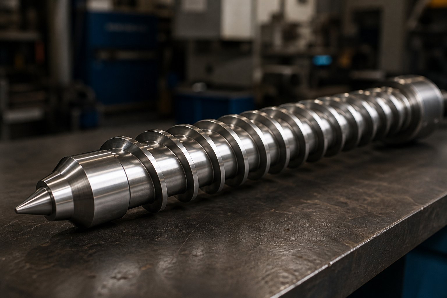
What the Injection Molding Screw Does and Why It Matters
Imagine a single component that controls how evenly your plastic melts, how fast your machine cycles, and how consistent every part comes out of the mold. That component exists — and it's the injection molding screw. Sitting inside the heated barrel of every injection molding machine, this helical-flighted steel shaft does far more than simply push pellets forward. It conveys, compresses, melts, and homogenizes raw polymer pellets into a perfectly uniform melt, then reverses its role entirely, acting as a plunger to inject that melt into the mold cavity under precisely controlled pressure.
An injection molding screw is a precision-engineered helical shaft that plasticates polymer pellets and injects the resulting melt into a mold under controlled pressure.
No other single part in the plasticizing system has a greater influence on melt quality, cycle time, or part-to-part repeatability. The screw's geometry, surface condition, and interaction with surrounding components determine whether you produce flawless parts or chase defects shift after shift.
What Is an Injection Molding Screw
At its core, an injection molding screw is a helically shaped metal shaft that rotates inside a heated barrel. Its screw-like flight design enables it to perform several tasks simultaneously: pulling solid pellets from the hopper, generating frictional and conducted heat to melt those pellets, blending in any colorants or additives, and accumulating a precise dose of molten plastic at the front of the barrel. When the shot is ready, a hydraulic or electric drive pushes the screw forward in a linear stroke, forcing the melt through the nozzle and into the mold cavity. This dual-action capability — rotation for melting plus linear motion for injection — is what makes the injection screw unique among plasticizing components.
Plastication, Recovery, and the Dual Role of the Screw
Two terms you'll encounter constantly in injection molding are plastication and recovery. Plastication refers to the entire process of converting solid pellets into a homogeneous, injectable melt. Recovery is the specific phase during which the screw rotates, plasticates the next shot of material, and retracts rearward as molten plastic accumulates in front of it. Recovery time directly affects cycle time — a screw that recovers too slowly becomes the bottleneck of your entire operation. Once recovery finishes, the screw switches roles. It stops rotating and drives forward as a ram, delivering the accumulated melt into the mold at the speed and pressure your process demands. This constant alternation between rotary plasticator and linear ram is what defines the injection molding screw function explained in practical terms.
Injection Screw vs. Extrusion Screw at a Glance
If you've worked with extrusion, you might wonder how the two screw types differ. An extrusion screw is designed to generate high pressures and maintain a consistent, continuous flow of material over extended periods. It rotates in one direction without stopping, pushing melt through a die at a steady rate. An injection screw, by contrast, must provide rapid and precise control over melt homogenization, injection speed, and pressure — all within a cyclical, stop-start process. The critical difference between an injection screw and an extrusion screw is that reciprocating injection stroke. Extrusion screws never move axially; injection screws must slide forward like a plunger every cycle, then retract during recovery. This dual motion demands tighter manufacturing tolerances, a non-return valve at the screw tip, and design considerations that balance both plasticating efficiency and injection precision.
Understanding what the screw does is just the starting point. Its performance is shaped by a set of measurable geometry parameters — length-to-diameter ratio, compression ratio, flight depth, and pitch — each acting as a tuning lever that directly controls melt temperature, mixing quality, and throughput. These geometric details are where screw design truly comes alive.
Essential Screw Geometry Parameters That Control Plasticating Performance
Every injection molding screw carries its performance blueprint in its physical dimensions. Change the depth of a single channel by a fraction of an inch, and you'll shift melt temperature, shear rate, and output volume in ways that ripple through every part you produce. The geometry of the screw isn't just a manufacturing spec on a data sheet — it's a set of tuning levers that practitioners can adjust to match specific resins, part requirements, and cycle-time targets. Understanding how screw geometry affects melt quality starts with four core parameters: L/D ratio, compression ratio, flight depth, and pitch.
The table below organizes these parameters into a quick-reference format before we explore each one in detail.
| Parameter | Definition | Typical Range | Effect on Melt Quality |
|---|---|---|---|
| L/D Ratio | Flighted length of the screw divided by its nominal outside diameter | 20:1 to 26:1 | Higher ratios increase residence time, improve melt homogeneity, and allow more uniform shear heating without degradation |
| Compression Ratio | Ratio of feed-zone channel depth to metering-zone channel depth | 1.5:1 to 4.5:1 | Higher ratios increase compaction, shear heat, and melt uniformity; too high can degrade shear-sensitive resins |
| Flight Depth (Channel Depth) | Distance from the top of the flight to the screw root in a given zone | Varies by zone and screw diameter | Deeper channels boost throughput but reduce shear; shallower channels increase shear and melt uniformity |
| Pitch | Axial distance from one flight to the next corresponding flight | Typically equal to screw diameter (square pitch) | Affects conveying rate and residence time; non-standard pitches alter material transport speed and shear exposure |
| Helix Angle | Angle of the flight relative to a plane perpendicular to the screw axis | ~17.66° for square-pitch designs | Influences the balance between forward conveying force and cross-channel shear flow |
L/D Ratio and Its Influence on Melt Homogeneity
When someone describes a screw as "20:1" or "24:1," they're referencing its L/D ratio — the flighted length of the screw divided by its outer diameter. Think of it as a measure of how much "processing runway" the resin has before it reaches the front of the barrel. Most injection molding screws fall in the 20:1 to 26:1 range, with 20:1 being common on many standard machines.
Why does that ratio matter so much? A longer L/D gives the polymer more time and distance to absorb heat, undergo shear, and blend into a consistent melt. Here's what shifts as L/D increases:
- More uniform shear heat — the resin is worked over a greater length, so heat builds gradually rather than concentrating in a short zone.
- Better mixing — additional screw length creates more opportunities for the melt to fold and re-fold, improving the homogeneity of colorants, additives, and temperature distribution.
- Greater residence time — the material spends longer inside the barrel, which can be beneficial for larger shots or resins that need gentle, extended melting.
However, a longer L/D isn't always better. Excessive residence time can cause thermal degradation in heat-sensitive polymers. The injection molding screw L/D ratio explained in practical terms is really about matching the processing runway to the resin's melting behavior and the cycle demands of the application.
Compression Ratio Explained for Semi-Crystalline and Amorphous Resins
If L/D ratio determines how long the resin travels, compression ratio determines how hard it gets squeezed along the way. This ratio is calculated by dividing the feed-zone channel depth by the metering-zone channel depth. A screw with a feed depth of 0.300 inches and a metering depth of 0.100 inches, for example, has a 3:1 compression ratio.
The compression ratio for injection screw design is arguably the single most resin-sensitive geometry parameter. Increasing it delivers greater shear heat, improved heat uniformity, and stronger compaction of the solid bed against the barrel wall. But push it too high for a shear-sensitive material, and you risk scorching, molecular degradation, or warped parts.
This is where the distinction between resin families becomes critical:
- Semi-crystalline resins (PE, PP, PA, POM) undergo a sharp solid-to-liquid transition and absorb significant energy at their melt point. They generally require higher compression ratios — often in the 2.5:1 to 4.0:1 range — to deliver enough compaction energy to break through that crystalline structure and achieve a uniform melt.
- Amorphous resins (ABS, PC, PMMA) soften gradually over a broad temperature range. They typically perform well at lower compression ratios, around 1.5:1 to 2.5:1, because they don't need as aggressive a squeeze to transition into a flowable state.
Selecting the right injection screw compression ratio for semi-crystalline resins versus amorphous materials can mean the difference between a stable, repeatable process and one plagued by unmelts or degradation. When the compression ratio changes, barrel temperature setpoints and screw RPM often need adjustment to keep shear heating within safe limits — an interaction we'll examine more closely when discussing barrel integration.
Flight Depth, Pitch, and Helix Angle Defined
Flight depth — also called channel depth — is the distance measured from the top of the screw flight down to the root. It varies deliberately across the three functional zones. In the feed zone, deep channels accept a large volume of solid pellets. In the metering zone, shallow channels restrict the flow, generating consistent shear and pressure. The progressive change in flight depth across the transition zone is what drives the compression ratio discussed above.
Adjusting screw flight depth and pitch parameters lets designers fine-tune two competing needs: throughput and shear intensity. Deeper channels move more material per revolution but apply less shear, resulting in lower melt temperatures and potentially less uniform mixing. Shallower channels reduce volumetric output but increase shear rate, promoting better temperature uniformity and dispersion — an advantage for color-critical or additive-heavy applications.
Pitch is the axial distance the flight advances in one full turn. Most general-purpose injection screws use a square-pitch design, where the pitch equals the screw's nominal outer diameter. A 60 mm screw, for instance, would have a 60 mm pitch. This standard geometry delivers a reliable balance between conveying efficiency and shear exposure. Non-standard pitches do exist for specialized applications — a shorter pitch slows conveying and increases residence time, while a longer pitch accelerates material transport.
Helix angle is closely tied to pitch. On a square-pitch screw, the helix angle works out to roughly 17.66 degrees. This angle determines how the polymer splits its movement between traveling forward along the barrel and circulating across the channel width. A steeper helix angle increases cross-channel flow, which enhances mixing but reduces forward conveying efficiency.
Together, these geometric parameters — L/D ratio, compression ratio, flight depth, pitch, and helix angle — form an interconnected system. Changing one parameter inevitably shifts the balance of the others. A screw optimized for high throughput on polyethylene, for example, would struggle with the low shear tolerance of PVC. This interdependency is precisely why understanding the three functional zones of the screw — feed, transition, and metering — is so essential to putting geometry into practical context.
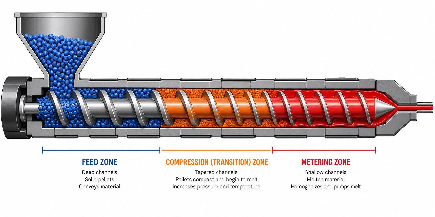
Inside the Three Functional Zones of the Injection Molding Screw
Geometry parameters like L/D ratio and compression ratio don't operate in the abstract — they express themselves through three distinct zones along the screw's length, each engineered for a specific stage of the plasticating process. The injection molding screw feed, transition, and metering zones work as a coordinated sequence, and what happens in each zone directly determines whether you end up with a homogeneous, injectable melt or a stream riddled with temperature variation, unmelted pellets, or degraded polymer. Let's walk through each zone in the order your resin experiences it.
- Pellets drop from the hopper into the deep-channeled feed zone and are conveyed forward as the screw rotates.
- Solid pellets compact against the barrel wall, and a thin melt film begins forming on the hot barrel surface.
- The advancing flight scrapes the melt film off the barrel wall, collecting it into a growing melt pool on the pushing side of the channel.
- The solid bed narrows progressively as more material melts, while decreasing channel depth in the transition zone increases compaction and shear.
- Fully molten polymer enters the metering zone, where shallow, uniform channels apply consistent shear to homogenize temperature and viscosity.
- Pressurized melt passes through the non-return valve and accumulates in front of the screw tip, forming the shot.
- The screw retracts slightly (decompression) after recovery to relieve nozzle pressure and prevent drool before the next injection stroke.
This pellet-to-melt journey sounds orderly on paper, but in practice, each zone introduces variables that can make or break part quality. Here's how.
Feed Zone and the Mechanics of Solids Conveying
Imagine the feed zone as a loading dock — its job is to accept pellets from the hopper and push them forward reliably. To do this, the flights are cut deep, creating large open channels that can accommodate the bulk density of solid granules. But simply having deep channels isn't enough. Solids conveying in the injection molding screw feed zone depends almost entirely on a friction differential between two surfaces: the barrel wall and the screw root.
Here's the key principle: the barrel surface must grip the pellets more than the screw surface does. When the barrel's friction coefficient is higher than the screw root's, pellets are dragged forward along the barrel wall while the rotating screw flights push them ahead. If that friction balance reverses — say, because the barrel wall is polished smooth from wear or the screw root is roughened — pellets spin in place instead of advancing. You'll notice this as erratic feeding, inconsistent recovery times, or shot-size variation with no obvious cause.
This is why many barrels feature a grooved feed section or textured liner in the first few diameters of length. The grooves mechanically lock pellets against the barrel, ensuring they move forward regardless of how slippery the resin might be. Some processors also water-cool the feed throat to keep pellets solid and rigid, preventing them from softening prematurely and smearing across the screw surface — a condition that would kill the friction differential and starve downstream zones of material.
How the Transition Zone Melts the Solid Bed
The transition zone — also called the compression zone — is where the real transformation happens. As channel depth decreases progressively along this section, the solid pellets compact into a dense bed pressed tightly against the heated barrel wall. A thin melt film forms at the barrel surface through conduction, and this is where things get interesting.
The classic Maddock melting model describes what happens next. As the screw rotates, the advancing flight scrapes the thin melt film off the barrel wall. Rather than staying distributed around the solid bed, this scraped melt collects into a melt pool on the pushing side of the flight channel. Meanwhile, the remaining solid bed — still intact on the trailing side — continues to shrink in width as more material melts from its barrel-side surface.
Picture it this way: the solid bed is being consumed from the outside in, like an ice cube melting in warm water, except the "warm water" is continuously being generated by barrel heat conduction and, critically, by viscous shear within the melt film itself. In many processing scenarios, shear heating contributes the majority of the melting energy — the barrel heaters primarily establish the thermal boundary that initiates the melt film, while mechanical work from the rotating screw drives most of the actual phase change.
The length and taper rate of the transition zone matter enormously. A longer, more gradual compression zone gives harder-to-melt resins — especially semi-crystalline polymers with sharp melting points — more distance to complete the solid-to-liquid transition. Shortening this zone accelerates compression, which works well for easy-melting amorphous materials but risks leaving unmelted pellets in the melt stream if the resin can't absorb energy fast enough. Adjusting zone length ratios is one of the most powerful design levers for matching a screw to a specific resin family.
Metering Zone Pressure and Melt Homogeneity
By the time polymer reaches the metering zone, it should be fully molten — but "fully molten" doesn't automatically mean "ready to inject." The metering zone's shallow, uniform channels serve a critical finishing role. They apply consistent shear across the entire melt stream, evening out temperature gradients that developed during melting and ensuring viscosity is uniform from the center of the channel to its edges.
You can think of this zone as the quality-control station of the plasticating process. The constant channel depth generates a steady, predictable shear rate that homogenizes the melt and builds the pressure needed to push material through the non-return valve and into the shot accumulation area. Without adequate metering-zone length, even a well-melted polymer can arrive at the screw tip with temperature differences of several degrees across its cross-section — enough to cause warpage, sink marks, or dimensional variation in the finished part.
The metering zone function in a plasticating screw also acts as a melt pump, smoothing out the pulsating delivery that naturally occurs as the solid bed breaks up in the transition zone. A properly designed metering section delivers melt at a stable flow rate, which translates directly to consistent cushion and repeatable shot weight during injection.
After recovery is complete — meaning the screw has rotated enough to accumulate the full shot volume — most machines perform a short decompression stroke, also called suck-back. The screw retracts a small distance without rotating, pulling slightly away from the accumulated melt. This rearward movement relieves residual pressure at the nozzle tip, preventing molten polymer from drooling or stringing into the mold between cycles. Setting decompression distance too high can draw air into the melt; setting it too low leaves enough nozzle pressure to cause drool. Finding the right balance depends on resin viscosity, nozzle geometry, and check valve condition.
Each of these three zones performs its function in isolation on paper, but in the real machine, they interact constantly with an external partner: the heated barrel. The balance between the screw's internally generated shear heat and the barrel's externally applied conductive heat determines whether your plasticating system runs at peak efficiency or fights itself every cycle.
How the Screw and Barrel Work Together as an Integrated System
Treating the screw and barrel as separate components is one of the most common oversights in injection molding troubleshooting. In reality, the screw and barrel system in injection molding functions as a tightly coupled heat-exchange and pressure-generation unit. The barrel supplies external conductive energy through resistance heater bands, while the rotating screw generates internal energy through viscous shear. When these two heat sources are properly balanced, you get a stable, homogeneous melt delivered cycle after cycle. When they fight each other, you get degradation on one end of the spectrum or unmelted pellets on the other.
Balancing Barrel Heater Zones with Screw Shear Heat
Picture the barrel as a series of independently controlled thermal zones — typically labeled feed, center, front, and nozzle — each wrapped with its own resistance heater band and monitored by a thermocouple embedded in the barrel wall. These zones provide the conductive heat that initiates melting at the barrel surface. But here's what many operators underestimate: the thermocouple reads barrel wall temperature, not the actual melt temperature at the channel center. The real melt condition depends heavily on shear heat generated by the screw's rotation, compression, and mixing action.
Research from FCS demonstrates that increasing screw speed from 10 RPM to 100 RPM can raise average melt temperature by approximately 3 degrees Celsius, while localized hot spots may spike more than 15 degrees Celsius above the heater setpoint. In high-viscosity materials like PVC or PEEK, shear heat can easily exceed the energy contributed by the barrel heaters themselves.
This barrel heater zone and screw shear heat balance matters enormously when you consider screw geometry. A high-compression-ratio screw intensifies shear — pair it with aggressive barrel temperature setpoints, and you risk over-shearing heat-sensitive resins like PVC or POM, causing thermal degradation, discoloration, or even hazardous off-gassing. Flip the scenario: a low-compression screw running with conservative barrel temperatures may not deliver enough total energy to fully melt semi-crystalline polymers, leaving solid particles in the melt stream. The takeaway? Barrel zone setpoints should never be established in isolation. They must account for the shear contribution dictated by the specific screw geometry installed in the machine.
Why Screw-to-Barrel Clearance Is a Critical Performance Metric
Between the outer diameter of every flight and the inner bore of the barrel sits a precision-controlled gap — typically just a few thousandths of an inch on new equipment. This screw-to-barrel clearance might seem trivial, but it governs how effectively the screw can build pressure and convey material forward without backward leakage.
As this clearance widens through normal wear, melt begins leaking backward over the flight lands during the pressurization phase. The consequences compound quickly: the screw must work harder to maintain output, shear heating increases from the higher RPM needed to compensate, and shot-to-shot repeatability deteriorates. Industry analysis from Plastics Technology confirms that higher-viscosity resins tolerate more clearance before output drops noticeably, while lower-viscosity materials like PP leak more aggressively at the same wear level.
How do you know when your clearance has crossed the line? Watch for these warning signs:
- Recovery time gradually increases without any change in process parameters or resin lot
- Cushion becomes inconsistent from shot to shot, even with stable back pressure settings
- You need to increase screw RPM to maintain the same shot size — a clear sign of backward leakage eating into forward output
- Visible melt leakage appears at the nozzle during decompression, indicating pressure is no longer being contained effectively
- Reject rates climb with no corresponding change in mold, material, or temperature settings
Screw to barrel clearance measurement is typically performed using lead casting techniques or precision bore gauging at multiple positions along the barrel — feed, center, and discharge. Comparing these readings against the original specifications reveals exactly where wear is concentrated and how far it has progressed.
Matching Barrel Liner and Screw Metallurgy
The barrel bore material and screw metallurgy must be selected as complementary partners, not in isolation. Standard nitrided steel barrels offer good initial wear resistance for unfilled commodity resins. However, nitrided layers are relatively thin — once abraded through, the softer substrate beneath wears rapidly, and clearance opens up at an accelerating rate.
For demanding applications, a bimetallic barrel liner for injection molding provides substantially longer service life. These liners use centrifugal casting to bond a thick, wear-resistant alloy — typically a nickel-based matrix embedded with hard carbide particles — to the inside of the barrel shell. The result is a bore surface that resists both abrasive attack from glass fibers and mineral fillers and corrosive attack from acidic off-gases produced by resins like PVC or flame-retardant compounds.
Selecting the right barrel liner depends on the dominant wear mechanism in your process. High-filler compounds demand maximum abrasion resistance. Corrosive resins require alloys with superior chemical resistance. And in many real-world operations, both wear modes act simultaneously, which is why the best screw-barrel pairings match a hardened screw surface with a liner alloy engineered for the specific resin family being processed.
This integrated perspective — screw geometry, barrel heat, and clearance working together — sets the stage for understanding one more critical interface: the check valve and screw tip assembly that sits at the very front of the plasticating unit, controlling whether all that carefully prepared melt actually reaches the mold in the exact volume you intended.
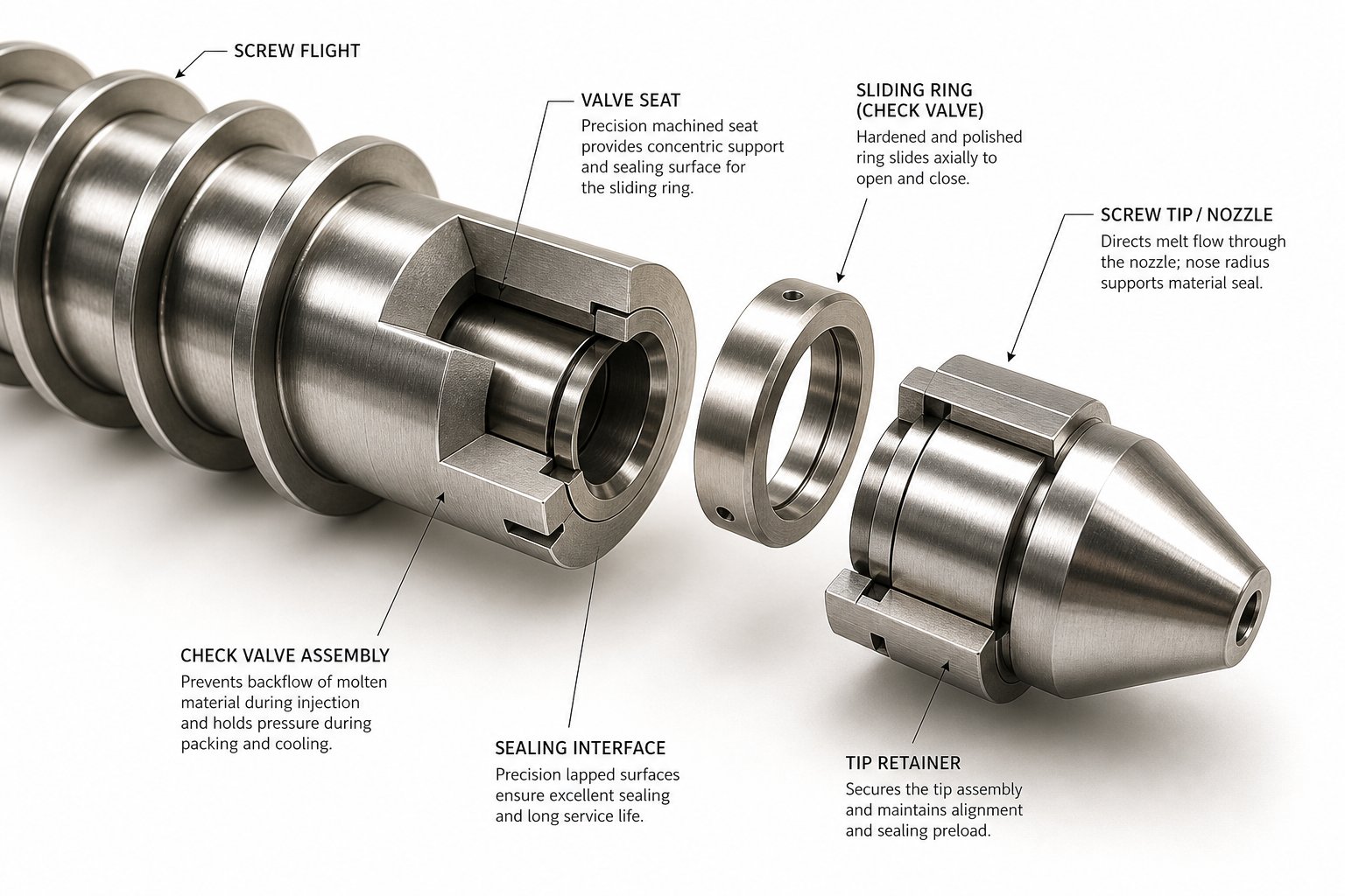
The Check Valve and Screw Tip Assembly: How It Controls Shot Consistency
You've spent time dialing in barrel temperatures, optimizing screw geometry, and fine-tuning zone ratios. But all of that careful plasticating work funnels through a single bottleneck at the very front of the screw: the check valve and screw tip assembly. This small assembly — often overlooked during maintenance — acts as the gatekeeper between your melt preparation and your mold. If it doesn't seal properly, every shot you inject carries a different volume of material, and no amount of downstream process adjustment can compensate for what's leaking backward behind the screw tip.
How the Non-Return Valve Ensures Shot Consistency
The injection molding non-return valve function is deceptively simple: it allows molten plastic to flow in only one direction. During recovery, as the screw rotates and builds up the next shot, melt needs to pass freely through the valve and accumulate in the space ahead of the screw tip. During injection, when the screw drives forward as a ram, the valve must seal completely to prevent any melt from leaking backward over the screw flights. Think of it as a one-way gate — open while loading, locked while firing.
Consider a sliding ring check valve, the most widely used design in the industry. Here's how it works in practice: as the screw rotates during recovery, the forward flow of melt pushes the ring forward on the screw tip, opening an annular gap between the ring and its rear seat. Melt streams through this gap, past the screw tip's flow channels, and into the shot accumulation zone. The moment the screw reverses direction to inject, injection pressure forces the ring rearward. It seats against a precision-machined seal surface — called the seat or retainer — and simultaneously presses its outer diameter against the barrel wall. Two seals form simultaneously: ring-to-seat and ring-to-barrel. Plastics Technology notes that the pressure acting on these seals during injection can reach 20,000 to 45,000 psi, making even microscopic wear on the sealing surfaces consequential.
Why does this matter so much? Because how well the check ring seals determines the consistency of your shot size and cushion position. If the ring doesn't seat perfectly — whether from wear, contamination, or partially melted pellets lodged in the seal — melt bleeds backward during injection. You effectively lose volume from every shot, and that loss varies randomly from cycle to cycle. The result is fluctuating part weight, shifting dimensions, and a cushion position that drifts unpredictably.
Back Pressure, Screw RPM, and Recovery Time Interactions
The check valve doesn't operate in isolation. Three key process parameters interact directly with its performance, and adjusting any one of them changes how reliably the valve seats and how consistent your melt arrives at the screw tip.
Back pressure is the resistive force the machine applies against the screw as it retracts during recovery. Every pellet that enters the barrel must be pushed forward through the flights and past the check valve against this resistance. The back pressure setting for an injection molding screw serves multiple purposes: it increases melt density by compacting the polymer, improves mixing of colorants and additives, and drives trapped air out of the melt. Typical back pressures for unfilled resins fall in the 500 to 750 psi plastic pressure range, though glass-filled or degradation-sensitive materials often require lower settings.
Setting back pressure too low introduces real problems. Without adequate resistance, the screw retracts too easily — sometimes described as "augering" — and the resulting melt has low density with pockets of entrapped air. You'll see this as splay marks, internal voids, or erratic shot weight. Conversely, pushing back pressure too high forces the melt through the flights under excessive shear. UL Prospector's injection molding reference notes that back pressure settings above approximately 300 psi risk thermally degrading the resin through excessive shearing, while also extending recovery time and increasing wear on the screw and barrel.
Screw RPM directly controls how fast recovery occurs and how much shear heat develops in the melt. Higher RPM shortens recovery time — which is beneficial when plasticating is the bottleneck in your cycle — but also generates more frictional heating. Increasing screw speed has a substantially larger effect on melt temperature than increasing back pressure, making RPM the more powerful lever for thermal management. However, excessive speed can over-shear sensitive polymers, degrade fiber length in reinforced resins, and push melt through the check valve so aggressively that the valve doesn't seat cleanly when injection begins.
Decompression distance (suck-back) is the short rearward stroke the screw makes after recovery to relieve residual nozzle pressure. While its primary purpose is to prevent drool at the nozzle tip between cycles, decompression also affects check valve behavior. An adequate decompression stroke helps the ring settle onto its seat before the injection phase begins. Too little decompression may leave the valve in a partially open position, allowing backflow at the start of injection. Too much can draw air into the melt front, creating voids or splay in the next shot.
The interplay between these three parameters — back pressure, RPM, and decompression — determines whether the check valve functions as a reliable one-way seal or becomes a source of process instability. Adjusting one almost always requires revisiting the others to maintain a stable window.
Comparing Sliding Ring, Ball Check, and Poppet Valve Designs
Not all non-return valves work the same way. Three principal designs dominate the market, each with distinct mechanical behavior, strengths, and trade-offs. Choosing the right one depends on your resin, part tolerance requirements, and maintenance philosophy.
| Type | Mechanism | Best For | Wear Sensitivity | Ease of Cleaning |
|---|---|---|---|---|
| Sliding Ring | Ring slides axially on the screw tip without rotating; seats rearward against a seal surface during injection to block backflow | General-purpose molding; wide range of commodity and engineering resins | Moderate — ring-to-seat and ring-to-barrel surfaces wear over time, but no rotational scoring on the barrel wall | Good — simple disassembly; fewer components to inspect and replace |
| Ball Check | A free-floating ball moves between a forward seat (open during recovery) and a rear seat (sealed during injection) | Small-diameter barrels; micro-molding; applications requiring compact valve assemblies | High — ball and seat surfaces are small, concentrating wear; seal degradation can be rapid with abrasive resins | Easy — minimal parts; ball and seats are simple to inspect visually |
| Poppet (Locking Ring) | Ring locks to the screw and rotates with it during recovery; moves axially to seat during injection | Applications where processors believe rotational locking improves seal consistency | High — rotational contact scores both the ring and the barrel bore, accelerating wear on both components simultaneously | Moderate — locking features can trap degraded material; requires more thorough inspection |
The sliding ring design remains the most popular for a reason: it avoids rotational contact with the barrel wall during plastication. Because the ring only slides axially — forward during recovery, rearward during injection — it doesn't generate the circumferential scoring that locking-ring designs inflict on the barrel bore. John Bozzelli, founder of Injection Molding Solutions, has documented locking-ring valves showing severe scoring and carbon buildup after only about 2,000 hours of operation, noting that the barrel itself may need replacement along with the worn valve.
Ball check valves suit compact assemblies and small-barrel applications where space constraints prevent a full sliding-ring assembly. Their weakness is durability — the small contact area between ball and seat concentrates wear forces, and once the seal degrades, shot-weight variation escalates quickly.
Regardless of which design you run, check valve wear and shot weight variation share a direct cause-and-effect relationship. A valve that sealed perfectly six months ago may now leak enough to shift your cushion position by several millimeters — subtle enough to go unnoticed until reject rates climb. Periodic visual inspection of the ring, seat, and screw tip during scheduled maintenance is the most reliable way to catch wear before it reaches your parts. Stepped-angle or radiused seat geometries can also extend seal life significantly compared to standard near-mating-angle designs.
The check valve is ultimately the final quality gate in the screw tip assembly for injection molding — the last point of control before melt enters the mold. When it functions well, shot weight stays locked in and cushion holds steady. When it doesn't, inconsistencies cascade into every part. Recognizing these valve-related symptoms is part of a broader skill: tracing processing defects back to their screw-side root causes, whether the issue originates in valve wear, geometry mismatch, or insufficient mixing.
Troubleshooting Common Screw-Related Processing Defects
A worn check valve leaking a few thousandths of an inch is one thing. But what about the defects that seem to appear out of nowhere — black specks in clear parts, solid pellets embedded in a sprue, color streaks that won't blend out no matter how much back pressure you add? These are the kinds of problems that send operators chasing temperature settings and material lots when the real culprit is sitting inside the barrel, spinning at 100 RPM. Many injection molding defects related to screw geometry go undiagnosed because processors don't connect what they see on the part to what's happening inside the plasticating unit.
The table below maps five common screw-related defects to their symptoms, root causes, and corrective actions — giving you a structured starting point before diving into the details of each one.
| Defect | Symptoms | Screw-Related Root Cause | Corrective Action |
|---|---|---|---|
| Unmelted pellets | Solid particles visible in the part, sprue, or runner; rough surface patches | Insufficient compression ratio; too-short transition zone; excessive screw speed reducing residence time | Reduce screw RPM (process fix); switch to a screw with a higher compression ratio or longer transition zone (design fix) |
| Black specks and degradation | Dark spots, brown streaks, or burnt odor in molded parts | Excessive residence time in an oversized screw; dead spots in a worn check valve; high-shear screw design paired with heat-sensitive resin | Right-size the screw to match shot volume (design fix); replace worn check valve (maintenance fix); reduce barrel temps and screw RPM (process fix) |
| Poor color or additive dispersion | Color streaks, uneven pigment distribution, visible additive agglomerates | Inadequate mixing from a general-purpose screw lacking dedicated mixing elements | Install a screw with an integrated mixing section — Maddock, Saxton, or pin mixer (design fix); increase back pressure moderately (process fix) |
| Inconsistent shot weight | Part weight varies cycle to cycle; cushion drifts unpredictably; short shots intermixed with flash | Check valve wear allowing backflow; excessive screw-to-barrel clearance; improper decompression settings | Replace check valve and inspect barrel bore (maintenance fix); optimize decompression distance (process fix) |
| Splay and silver streaks | Silver-white streaks radiating from the gate on the part surface | Moisture (most common), but also screw designs generating excessive shear that break polymer chains and release volatiles | Verify material drying first (process fix); if moisture is ruled out, switch to a lower-compression or lower-shear screw design (design fix) |
Having the overview is useful, but the real value is understanding why each defect connects to the screw and whether you need to adjust a parameter on your controller or invest in different hardware.
Unmelted Pellets and Degradation Traced to Screw Design
Finding unmelted pellets caused by injection screw design is one of the most frustrating defects to troubleshoot because the instinct is to crank up barrel temperatures. Sometimes that helps. Often, it doesn't — because the problem isn't a lack of heat but a lack of compressive work. When the screw's compression ratio is too low for the resin being processed, pellets pass through the transition zone without being adequately compacted against the barrel wall. That thin melt film described by the Maddock melting model never fully develops, and solid fragments survive all the way into the metering zone. A transition zone that's too short produces the same result — there simply isn't enough screw length for the solid bed to be consumed before the material enters the shallow metering section.
Excessive screw speed compounds the issue. Higher RPM shortens residence time, meaning each pellet spends fewer seconds in the melting zone. For easy-flowing amorphous resins, this rarely causes problems. For semi-crystalline polymers with sharp melt points — nylon, POM, HDPE — reduced residence time can leave a significant fraction of material unmelted. The low-cost fix is to slow the screw down and verify that recovery time isn't being pushed to its minimum just to shave cycle time. The capital fix, when process adjustments aren't enough, is a screw with a higher compression ratio or a longer transition zone matched to the resin's melting characteristics.
Black specks from screw degradation in injection molding represent the opposite end of the thermal spectrum. Instead of too little energy, you're dealing with too much — or with energy applied in the wrong place for too long. The most common screw-related cause is an oversized barrel. When the shot size uses only a small fraction of the barrel's capacity, melt sits in front of the screw for multiple cycles before being injected. Each cycle adds more heat exposure. Over time, thin layers of degraded polymer accumulate on the screw tip, check valve surfaces, and barrel wall. These carbonized deposits periodically break free and appear as black specks in otherwise clean parts.
Worn check valves create a related problem. As seal surfaces degrade, small pockets of stagnant melt form in the gaps — dead spots where polymer sits at elevated temperature cycle after cycle, slowly charring. High-shear screw designs paired with heat-sensitive resins like PVC or certain TPEs accelerate degradation even further, generating localized melt temperatures well above the barrel setpoint. The fix depends on the root cause: if the screw is oversized for the shot, downsizing the plasticating unit is the long-term solution. If dead spots in the check valve are the culprit, replacing the valve assembly and inspecting the screw tip for carbon buildup addresses the immediate issue.
Solving Poor Color Mix with Mixing-Element Screws
Imagine you're running a white part with 3% blue color concentrate, and every tenth shot shows a faint streak where the pigment didn't fully disperse. You increase back pressure, bump up barrel temperatures, and the streak fades — but never entirely disappears. This is a classic case of poor color dispersion from a mixing element screw gap: a general-purpose screw simply doesn't provide enough mixing action for demanding color applications.
Standard GP screws rely on the natural shearing action of the metering zone to blend colorants into the melt. For many applications, that's sufficient. But when you need tight color consistency — especially with high-ratio letdown concentrates or multi-pigment blends — the metering zone alone can't reorient and redistribute the melt enough times to eliminate streaks.
This is where dedicated mixing elements, integrated into the screw's metering section, make a measurable difference. As Plastics Technology explains, understanding the distinction between dispersive and distributive mixing is essential for selecting the right mixer:
- Maddock mixer — Primarily dispersive. Melt passes over a very narrow clearance where it experiences high shear, breaking apart pigment agglomerates. It also functions as a dam that prevents unmelted particles from passing downstream. Its tight clearances add some distributive mixing as well, but its strength is applying force to break things apart.
- Saxton mixer — Primarily distributive. Melt is divided many times and recombined with numerous reorientations, spreading colorant uniformly throughout the melt stream without generating excessive shear heat. This makes it well-suited for heat-sensitive materials that need better blending without thermal risk.
- Egan mixer — Combines strong dispersive and distributive characteristics. All flights are undercut, creating multiple high-shear regions along with substantial leakage flow and many reorientations. This dual-action design delivers high levels of both mixing types simultaneously.
Pin mixers offer yet another approach, using rows of pins protruding from the screw root to repeatedly split and recombine the melt flow. They're particularly effective for distributing low-concentration additives like UV stabilizers or nucleating agents.
The important takeaway from the Plastics Technology analysis is that no single mixer fits all situations. Processors should first determine whether their mixing problem is dispersive (pigment agglomerates need to be broken apart) or distributive (pigment is fine but unevenly spread), then select the mixer design that targets that specific deficiency. Increasing back pressure is a low-cost first step that improves mixing modestly by forcing melt through the flights under more resistance — but when the GP screw's inherent mixing capacity has been maxed out, a mixing-element screw is the only path to consistent color.
Shot Weight Variation and Its Screw-Side Root Causes
Few defects cause more downstream chaos than inconsistent shot weight. Parts oscillate between short shots and flash, dimensions drift in and out of tolerance, and assembly operations downstream reject parts at random intervals. The screw side of this problem typically involves three overlapping causes.
First, and most directly, check valve wear and shot weight variation share a near-linear relationship. As the valve's sealing surfaces degrade — ring-to-seat clearance opens, or the ring face develops wear grooves — more melt leaks backward during the high-pressure injection phase. That backflow subtracts directly from the delivered shot volume, and because the amount of leakage varies with injection pressure, melt viscosity, and valve position, the loss is never the same twice. The result is shot-to-shot weight scatter that no process parameter can fully compensate for.
Second, excessive screw-to-barrel clearance amplifies the problem. As flight O.D. wears down or the barrel bore enlarges, melt leaks backward over the flights during both recovery and injection. The screw loses pumping efficiency, meaning it takes more revolutions — and more time — to build the same shot volume. Even small clearance increases shift the process window, requiring higher RPM and back pressure settings just to maintain output. Those higher settings, in turn, increase shear heat and accelerate further wear, creating a feedback loop that narrows the stable operating window cycle by cycle.
Third, improper decompression settings can destabilize the cushion. Too much suck-back pulls air into the melt front, introducing compressible voids that change the effective shot volume unpredictably. Too little leaves residual pressure at the nozzle, causing drool that removes material from the next shot's volume. Finding the correct decompression distance — typically just enough to relieve nozzle pressure without drawing air — requires testing specific to your resin viscosity, nozzle geometry, and valve type.
For each of these three causes, the diagnostic approach is the same: measure first, then decide. Check the cushion position trend over 50 to 100 cycles. If it's drifting or scattering beyond your tolerance band, inspect the check valve for wear. Gauge the barrel bore at feed, center, and discharge positions to quantify clearance. Review decompression settings against actual nozzle drool behavior. Only after isolating the dominant source can you decide whether a process adjustment solves the problem — or whether replacing worn components is the real answer.
Splay and silver streaks deserve a brief note in this context because they're often misattributed entirely to moisture. While inadequate drying is the leading cause, screw designs that generate excessive shear can produce identical surface defects by mechanically breaking polymer chains. Chain scission releases volatile byproducts — small molecules that flash to gas at the melt front, creating the characteristic silver streaks on the part surface. If you've verified that your material is properly dried and splay persists, a lower-compression screw or reduced screw RPM may resolve what appears to be a moisture problem but is actually a shear-induced degradation issue.
Recognizing which defects trace back to the screw — and whether the fix is a five-minute parameter change or a hardware replacement — is the dividing line between reactive troubleshooting and proactive process control. That same diagnostic mindset applies when evaluating the physical condition of the screw and barrel themselves, where gradual wear silently erodes the process window long before a visible defect appears on a part.
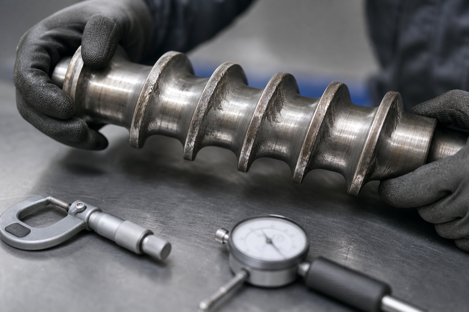
Screw Wear Indicators and When to Replace Your Components
Gradual wear doesn't announce itself with a machine alarm or a sudden catastrophic failure. Instead, it whispers — through slightly longer recovery times, a cushion position that drifts a millimeter wider than last month, or a reject bin that fills a little faster each week. Knowing how to measure injection screw barrel wear and interpret what those measurements mean separates shops that plan replacements from shops that react to breakdowns.
Every injection molding screw wears. The question isn't whether it happens, but how fast, by what mechanism, and when the degradation crosses the threshold where your process can no longer compensate. Understanding the wear mechanism active in your operation determines not only when to replace, but what material to specify for the replacement component.
Adhesive, Abrasive, and Corrosive Wear Mechanisms
Three broad categories describe virtually all screw and barrel wear. Each acts through a different physical or chemical process, leaves different evidence on the component surfaces, and demands a different metallurgical response.
Adhesive wear occurs when metal contacts metal under conditions of poor lubrication. In a properly functioning plasticating system, the polymer melt acts as a lubricant film between the screw flight O.D. and the barrel bore. But during startup — before the barrel is fully heated and a continuous melt film exists — or when material starvation leaves flights running dry against the barrel wall, direct metal-to-metal contact generates frictional welding at microscopic contact points. These micro-welds tear apart as the screw rotates, transferring material from one surface to the other. Over time, adhesive wear produces galling, scoring, and localized material loss concentrated on the flight lands and corresponding barrel bore positions. Improper alignment or incompatible geometries between screw and barrel accelerate this mechanism significantly.
Abrasive wear is the most common culprit in operations processing filled or reinforced resins. Glass fibers, calcium carbonate, talc, mineral fillers, and even certain pigments contain hard particles that act like microscopic sandpaper against flight surfaces and barrel walls. Abrasive wear on injection molding screw flights typically manifests as a progressive reduction in flight O.D., rounding of the leading flight edge, and a widening gap between flight tip and barrel bore. The harder the filler particle relative to the screw metallurgy, the faster this wear progresses. Glass fiber — with a Mohs hardness significantly above most tool steels — is particularly aggressive, capable of wearing through standard nitrided surfaces in a fraction of the time that unfilled resins would.
Corrosive wear results from chemical attack on metal surfaces. Certain resins release acidic byproducts during processing — PVC off-gases hydrochloric acid, acetals release formaldehyde, and flame-retardant compounds can produce corrosive halogen acids at elevated temperatures. These chemicals etch the metal surface, weakening the grain structure and making it vulnerable to mechanical removal by the flowing melt. Corrosive wear often appears as pitting or uniform surface erosion rather than the directional scoring typical of abrasive wear. It can also attack surfaces hidden from direct pellet contact, including check valve seal faces and screw root surfaces deep within the channel.
In many real-world operations, two or even all three mechanisms act simultaneously. A processor running glass-filled nylon with a flame-retardant package, for example, faces combined abrasive and corrosive attack — requiring metallurgical solutions that resist both wear modes.
How to Measure Screw-to-Barrel Clearance and Interpret Results
Suspecting wear is one thing. Quantifying it is another. Screw barrel clearance measurement methods give you hard numbers to compare against OEM specifications, removing guesswork from the replacement decision.
Measuring the screw: After pulling the screw from the barrel and cleaning off all residual resin, place it on a clean, flat surface. Using an outside micrometer — ideally with a parallel test bar spanning two flights for stability — measure the flight O.D. at multiple positions along the screw length: feed zone, mid-transition, and metering zone. Adams Engineers recommends recording these values at standard intervals so you can track wear progression over time and build a predictive wear profile for your specific resin and operating conditions. Also measure root diameter between flights and visually inspect for pitting, cracks, or washout areas on the root surface.
Measuring the barrel: With the screw removed, use a dial bore gauge and micrometer to measure the barrel I.D. at multiple positions along its length — every two to three inches provides good resolution according to Arlington Machinery's measurement protocol. Pay particular attention to the transition zone area, where melting occurs and where the combination of high pressure, abrasive solids, and elevated temperature concentrates the heaviest wear. Feed-end measurements near the hopper opening should also check for cracks or washout spots.
Lead casting offers an alternative approach when bore gauging equipment isn't available. A strip of soft lead wire is wrapped around the screw flight, the screw is inserted into the barrel, and the compressed lead is measured with a micrometer to determine the clearance at that position. While less precise than bore gauging, lead casting provides a quick field measurement that captures the actual flight-to-bore gap at specific points.
Interpreting results: Compare your measurements against the original OEM specification for flight O.D. and barrel bore diameter. A general industry guideline — referenced in the SPI Dimensional Guidelines — suggests that when screw-to-barrel clearance exceeds approximately twice the original specification, the component has reached its serviceable wear limit and replacement should be planned. However, this is a rule of thumb, not an absolute threshold. Always consult your machine manufacturer's specific documentation, as acceptable limits vary with screw diameter, resin viscosity, and application tolerance requirements.
The real power of measurement comes from trending. A single measurement tells you where you are today. Measurements taken at regular intervals — quarterly, semi-annually, or at every scheduled maintenance window — reveal your wear rate, allowing you to predict when to replace injection molding screw and barrel components before they degrade your process beyond acceptable limits.
Performance-Based Indicators That Signal Replacement Time
Not every shop has the luxury of pulling the screw on a strict schedule. Between measurement intervals, your machine gives you performance-based signals that wear is progressing — if you know what to watch for. These indicators don't require opening the barrel; they show up in your process data and part quality trends.
Watch for these patterns:
- Recovery time creeping upward — Log recovery time weekly. A gradual increase with no change in resin, barrel temperatures, or screw RPM indicates that backward leakage over worn flights is reducing forward pumping efficiency. The screw needs more revolutions to accumulate the same shot volume.
- Cushion consistency deteriorating — Track cushion position over 50 to 100 consecutive shots. If the standard deviation widens over weeks or months, worn check valve seals or enlarged flight clearance are allowing variable backflow during injection.
- Process window shrinking — When you find yourself making increasingly frequent adjustments to maintain acceptable parts — tweaking temperatures, pressures, and speeds that used to stay locked for months — the underlying hardware is likely losing its ability to deliver a consistent melt.
- Rising reject rates with no other process change — If material lot, mold, auxiliaries, and process settings remain constant but scrap climbs, worn plasticizing components become the prime suspect.
- Increased energy consumption — A worn screw and barrel force the drive motor to work harder to achieve the same throughput, as industry case studies confirm. If electricity usage rises despite stable production volume, wear-related inefficiency may be the cause.
- Visual evidence of incomplete melting or surface defects — Unmelted particles, splay marks, or discoloration that appear gradually and resist process correction point toward degraded plasticating capability.
Building a wear-monitoring program doesn't require expensive instrumentation. These actionable practices catch degradation early:
- Record recovery time at least weekly under consistent conditions (same resin, same RPM, same back pressure) and plot the trend
- Track cushion position standard deviation across production runs — a widening band is an early warning
- Visually inspect screw flights, check ring seal faces, and screw tip during every scheduled downtime — even a brief visual check reveals scoring, galling, or carbon buildup
- Measure barrel bore diameter at feed, center, and discharge positions during annual or semi-annual maintenance shutdowns
- Document screw flight O.D. at multiple positions each time the screw is pulled, building the wear profile that predicts remaining service life
Extending service life with wear-resistant materials: When your wear profile shows rapid degradation — especially in operations running glass-filled, mineral-loaded, or corrosive resins — standard nitrided steel may not deliver acceptable component life. Upgrading to tool steel screws, powder metallurgy (PM) steel alloys, or bimetallic barrel liners can extend service intervals by three to five times compared to conventional materials. The upfront cost is higher, but the reduction in unplanned downtime, scrap, and emergency replacement orders typically delivers a strong return.
When measurements confirm that clearance has exceeded acceptable limits — or when performance indicators converge to signal that your plasticating system can no longer hold the process window — the replacement decision is clear. At that point, sourcing matters. A supplier like NANHAIYA that offers custom screw barrels engineered to match your original geometry — or improve upon it for your specific resin and application — ensures the replacement restores full plasticating performance rather than introducing new variables. Their technical support for injection molding factories and maintenance teams helps confirm the right metallurgy, compression ratio, and check valve configuration before manufacturing begins, reducing the trial-and-error that comes with generic replacements.
Knowing when and how to replace worn components is essential. But equally important is making the right choice the first time — selecting a screw configuration matched to your resin, filler content, and part quality requirements from the start, rather than defaulting to a general-purpose design and hoping for the best.
A Practical Decision Framework for Screw Selection
Defaulting to a general-purpose screw because it "works for most resins" is how processors end up chasing defects that a properly matched design would have prevented from the start. Knowing how to select an injection molding screw for resin type, filler content, and part quality demands requires a structured decision path — not guesswork. The framework below walks you through five sequential steps that narrow the field from dozens of possible configurations down to one that fits your specific operation.
- Identify your primary resin family. Is it amorphous (ABS, PC, PMMA), semi-crystalline (PE, PP, PA, POM), or a specialty polymer (LSR, PVC, high-temperature PEEK)? This single distinction immediately filters out incompatible compression ratios, shear limits, and thermal profiles.
- Determine filler content. Unfilled, glass-fiber reinforced, or mineral-loaded? Fillers dictate wear-resistance requirements for both screw and barrel metallurgy. An injection screw for glass-filled resin applications needs hardened or bimetallic surfaces that unfilled commodity runs don't justify.
- Assess part quality priorities. Does the application demand optical clarity, structural strength, tight color consistency, or dimensional tolerance? Each priority shifts the balance between mixing intensity, shear level, and melt uniformity — factors that influence whether you need a standard metering section or a dedicated mixing element.
- Match to the right screw type based on the answers above. A general-purpose screw suits unfilled commodity resins with moderate quality demands. Low-compression designs protect shear-sensitive materials like PVC, which requires compression ratios between 1.5:1 and 2.5:1 for rigid formulations to prevent degradation. Barrier screws improve melting efficiency for semi-crystalline resins. Mixing-element screws solve color-critical applications that GP designs can't handle.
- Validate geometry. Confirm the compression ratio, L/D ratio, and check valve type align with every decision made in the previous steps. A barrier screw chosen for PA6-GF30, for example, still needs a bimetallic surface treatment and a sliding-ring check valve rated for abrasive service.
Starting with Resin Type to Narrow Screw Options
Resin family is the single most powerful filter in the selection process because it determines the melting behavior the screw must accommodate. Semi-crystalline polymers absorb a large amount of energy at a narrow melt point — the best screw design for semi-crystalline polymers uses higher compression ratios (typically 2.5:1 to 4.0:1) and often benefits from a barrier flight geometry that physically separates the solid bed from the melt pool. This separation prevents unmelted pellets from bypassing the transition zone and reaching the screw tip.
Amorphous resins, by contrast, soften gradually over a wide temperature range. They don't need aggressive compression to transition into a flowable state, and excessive shear can overheat them. GP screws with moderate compression ratios (1.5:1 to 2.5:1) typically perform well. Specialty polymers occupy their own territory entirely: PVC's thermal sensitivity and tendency to release hydrochloric acid demand corrosion-resistant metallurgy, low compression ratios, and precise temperature control. High-temperature resins like PEEK require screws built from alloys that maintain hardness at processing temperatures exceeding 400 degrees Celsius.
The barrier screw vs. general purpose screw selection decision often comes down to this resin-family distinction. Barrier designs add a secondary flight that creates a separate channel for melt, forcing solids to stay on the melting side until they're fully converted. For semi-crystalline resins with sharp melt transitions, this significantly reduces the risk of unmelts reaching the shot. For amorphous materials that melt easily, the added complexity of a barrier design rarely justifies its cost.
Filler Content and Its Impact on Screw Material Selection
Filler type and loading level shift the selection conversation from geometry to metallurgy. Unfilled resins like natural PP or clear PC impose minimal wear on standard nitrided screws and barrels — a well-maintained GP screw can last years in these applications. Add 10% glass fiber, and the equation changes dramatically. At 30% or higher glass loading, bimetallic or solid carbide screws become necessary to deliver acceptable service life.
Mineral fillers like talc and calcium carbonate fall between unfilled and glass-reinforced in terms of abrasiveness. They still accelerate wear, particularly on flight leading edges and check valve seats, but at a slower rate than glass fiber. The practical decision matrix looks like this:
| Filler Type | Loading Level | Recommended Screw Metallurgy |
|---|---|---|
| Unfilled | 0% | Nitrided tool steel (standard) |
| Mineral fillers (talc, CaCO3) | Up to 20% | Nitrided or chrome-plated |
| Glass fiber | 10-30% | Bimetallic (nickel-cobalt alloy) |
| Glass fiber | 30%+ | Solid carbide or PM steel |
| Corrosive resin (PVC, FR compounds) | Any | Corrosion-resistant bimetallic or coated |
Matching barrel liner metallurgy to the screw is equally important. Running a hardened screw inside a soft-bore barrel simply shifts the wear problem from one component to the other — and barrel replacement costs significantly more than swapping a screw.
Matching Screw Type to Part Quality Requirements
Resin and filler get you to the right material and general geometry class. Part quality requirements fine-tune the selection within that class. Think of it as the final filter that separates a good screw choice from the ideal one.
Color-critical parts — consumer housings, cosmetic packaging, multi-color designs — demand superior distributive mixing. A GP screw running at elevated back pressure might get you close, but a screw with an integrated Saxton or pin mixer built into the metering section delivers the consistent reorientation needed to eliminate streaks. Structural parts, especially those requiring consistent fiber length retention in reinforced resins, benefit from lower-shear screw designs that avoid breaking fibers during plastication. Dimensionally critical parts with tight tolerances need rock-steady shot weight, which points toward a well-matched check valve design and a screw diameter that keeps barrel utilization in the ideal range.
That brings up a frequently overlooked factor: the screw diameter and shot size relationship. A common industry guideline recommends that the shot — including runners, sprues, and parts — should ideally consume between 20% and 80% of the barrel's melt capacity. Falling below 20% means the resin sits in the barrel for too many cycles, accumulating heat history and risking degradation. Plastics Technology's residence time analysis underscores how critical this calculation is — especially for thermally sensitive materials like PBT or PVC, where even modest excess residence time triggers decomposition. Exceeding 80% utilization, on the other hand, leaves almost no cushion margin and forces the screw to recover under strained conditions every cycle.
Specialty applications push beyond standard configurations entirely. Micro-molding — producing parts weighing fractions of a gram — requires ultra-small-diameter screws with precisely controlled metering volumes, often paired with separate injection plungers because conventional reciprocating screws can't deliver the positional accuracy needed at such small shot sizes. Multi-material molding involves co-injection or sequential screws, each sized and configured independently for its specific resin layer. In both cases, a standard GP screw isn't just suboptimal — it's physically incapable of meeting the application's demands.
Following this five-step framework doesn't guarantee a perfect outcome on the first try, but it systematically eliminates the mismatches that cause the majority of screw-related problems. Resin family defines your compression and shear boundaries. Filler content dictates metallurgy. Part quality requirements select the mixing and valve configuration. And shot-size-to-barrel-capacity ratio prevents residence time from becoming an invisible quality killer. With this configuration locked in, the final piece of the puzzle is choosing a supplier who can actually deliver — and support — the precise screw barrel solution your operation needs.
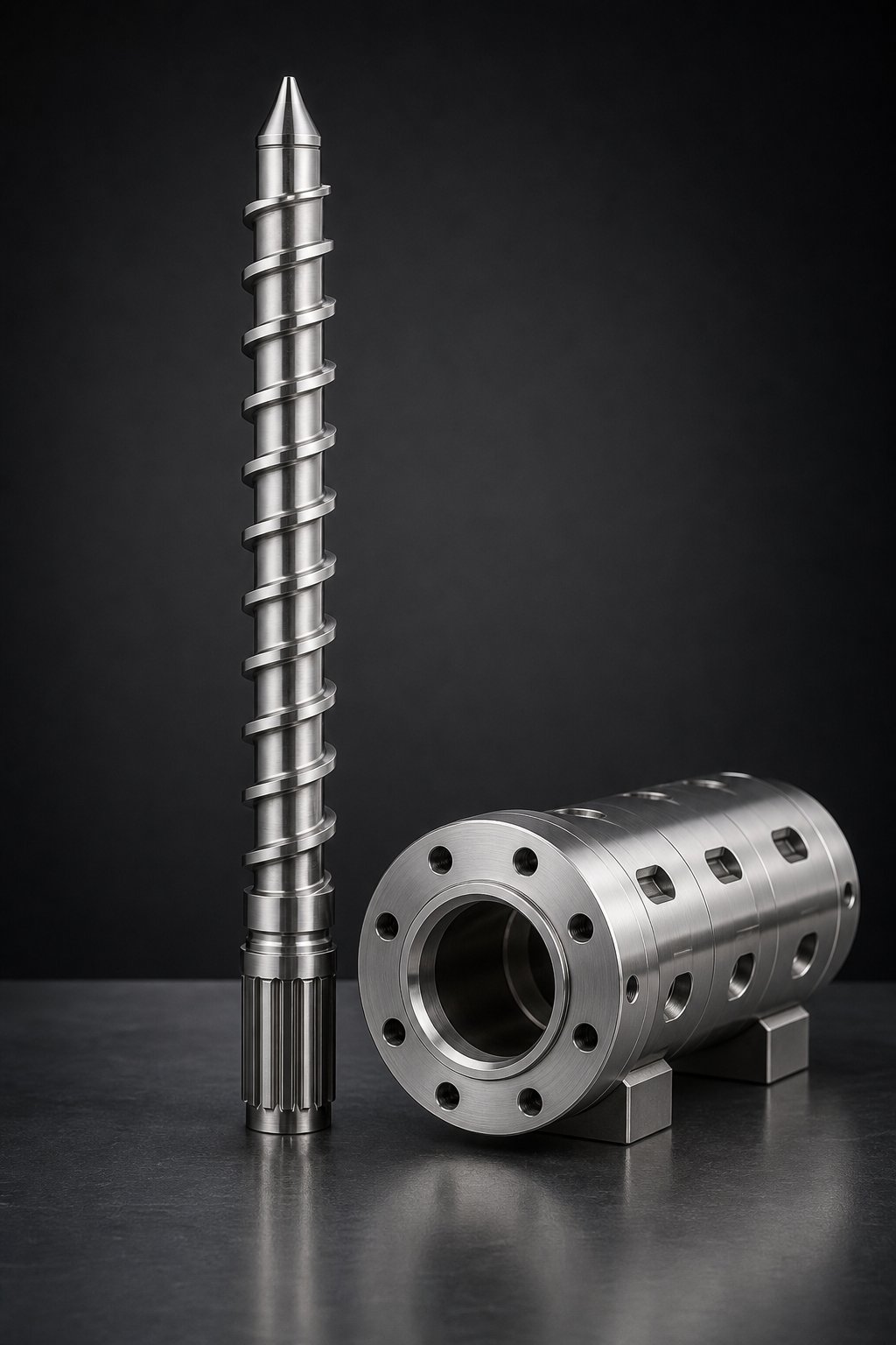
Choosing a Reliable Screw Barrel Partner for Your Operation
A five-step selection framework gives you the right screw configuration on paper. But a paper specification only becomes a functioning plasticizing component when a supplier turns it into hardened steel with micron-level precision. And this is where many operations stumble — choosing a replacement screw barrel for an injection molding machine based primarily on price, then spending months troubleshooting the process instability that a poorly manufactured component introduces. The supplier you choose shapes your machine's performance for years. Treating that decision with the same rigor you apply to screw geometry selection pays dividends far beyond the initial purchase.
What to Look for in a Screw Barrel Supplier
How do you evaluate a screw barrel supplier when every manufacturer claims precision, quality, and expertise? Start by testing those claims against four criteria that separate genuine manufacturing partners from commodity vendors.
Metallurgical expertise is the foundation. Your supplier should do more than offer a single steel grade for every application. They need the knowledge to recommend specific alloys based on your resin — nitrided tool steel for unfilled commodity runs, bimetallic liners with tungsten carbide dispersion for glass-filled compounds, corrosion-resistant alloys for PVC or flame-retardant processing. A supplier like NANHAIYA, which engineers custom screw barrels across a range of metallurgies for injection molding factories, demonstrates this capability by matching alloy selection to the specific wear mechanism active in your operation — not defaulting to a one-size-fits-all material.
Dimensional precision determines whether your replacement component performs like the original — or introduces new variables. Flight O.D., root diameter, concentricity between screw axis and flight geometry, and bore straightness all need to hold tolerances measured in thousandths of an inch. As industry analysis confirms, even a 0.02 mm deviation in bore geometry can destabilize melt pressure and shear distribution, producing dimensional inconsistency in finished parts. Ask potential suppliers what inspection equipment they use — CMM verification, bore honing to controlled surface roughness, and concentricity checks should be standard, not optional.
Customization capability matters because your application almost certainly has requirements that a catalog-standard screw won't fully address. Can the supplier modify zone lengths to extend the transition section for a difficult-to-melt semi-crystalline resin? Can they integrate a Maddock or pin mixer into the metering zone for a color-critical application? Can they adjust compression ratio to match a specific resin family without starting from scratch? These modifications are where a custom injection screw barrel manufacturer adds value that off-the-shelf replacements simply cannot.
Technical support is the criterion that reveals whether you're dealing with a partner or a parts vendor. A genuine partner advises on screw geometry based on your resin, part requirements, and machine specifications. They help troubleshoot when a new screw doesn't perform as expected. They understand the interplay between compression ratio, barrel temperature profiles, and check valve behavior discussed throughout this article — and they bring that understanding to the quoting process, not just the complaint process.
Why Custom Engineering Capability Matters for Your Operation
Imagine you've identified through measurement that your current screw's clearance has exceeded limits. You need a replacement. The easy path is ordering an exact duplicate from any available source. But what if the original screw was a general-purpose design that never quite matched your resin in the first place? What if your operation has shifted to a higher percentage of glass-filled material since the original screw was specified?
This is the moment where custom engineering capability transforms a routine replacement into a process improvement. A supplier with in-house design and manufacturing control can review your current screw geometry, compare it against your resin data and part quality history, and recommend targeted modifications — a slightly higher compression ratio, a longer transition zone, a mixing element added to the metering section — that address chronic issues the original design never solved.
NANHAIYA's injection molding screw barrel solutions exemplify this approach. Their replacement plasticizing components cover various machine brands, but their real strength lies in the technical consultation that precedes manufacturing. By working with your maintenance team to understand the specific resin, filler content, shot size, and quality targets, they engineer screw barrels for stable shot quality and sustained machine performance rather than simply replicating whatever was there before. That distinction — between duplicating a part and engineering a solution — is what separates a component supplier from a plasticizing partner.
Building a Long-Term Plasticizing Component Partnership
Screw and barrel replacement isn't a one-time event. Wear is continuous, and as your product mix evolves — new resins, new fillers, new part geometries — your plasticizing requirements evolve with it. The supplier you choose today will likely be the one you call again in 18 months, and again two years after that. Building that relationship on a foundation of technical depth, not just transactional pricing, pays compounding returns.
Use this checklist when evaluating any potential screw barrel supplier:
- Geometry confirmation: The supplier confirms screw geometry to OEM specifications or provides a documented custom design rationale explaining any deviations and their expected performance impact.
- Multiple metallurgy options: They offer a range of alloy choices — nitrided steel, tool steel, PM steel, bimetallic barrel liners — and can explain which option fits your resin and wear profile.
- Lead-time and inventory commitments: They maintain inventory or provide reliable lead times for common replacement sizes, minimizing production downtime during unplanned failures.
- Technical consultation: They supply engineering support for troubleshooting — not just order-taking, but active problem-solving when shot quality, recovery time, or wear rates don't meet expectations.
- Machine brand coverage: They manufacture replacement components compatible with your specific machine brand and model, ensuring dimensional and functional interchangeability.
- Quality documentation: They provide material certifications, dimensional inspection reports, and hardness testing results with every shipment — giving your maintenance team confidence that the component meets specification before installation.
The screw barrel supplier evaluation criteria above aren't abstract ideals. They're practical filters that protect your operation from the hidden costs of cheap replacements — costs that show up as extended downtime, scrap increases, and the frustration of a process that never quite stabilizes after a component swap. Choosing a partner that combines metallurgical knowledge, precision manufacturing, and genuine technical support ensures that every replacement screw and barrel moves your process forward rather than simply resetting the wear clock.
Your injection molding screw has been talking throughout this entire article — through its geometry, its wear patterns, its interaction with the barrel and check valve, and its influence on every defect and quality metric your operation tracks. Listening to what it tells you, measuring what it shows you, and partnering with suppliers who understand what it needs — that's the difference between a plasticizing system you manage and one that manages you.
Frequently Asked Questions About Injection Molding Screws
1. What is the ideal L/D ratio for an injection molding screw?
Most injection molding screws use an L/D ratio between 20:1 and 26:1. A higher L/D ratio provides more residence time and a longer processing runway, which improves melt homogeneity and allows gradual shear heating. However, excessively long L/D ratios can cause thermal degradation in heat-sensitive polymers. The best ratio depends on your resin family and cycle-time requirements — semi-crystalline materials with sharp melt points often benefit from ratios closer to 24:1 or 26:1, while easy-melting amorphous resins perform well at 20:1.
2. How do I know when my injection molding screw needs to be replaced?
Key indicators include gradually increasing recovery time with no process changes, inconsistent cushion position from shot to shot, the need to raise screw RPM just to maintain shot size, rising reject rates, and visible melt leakage at the nozzle during decompression. Quantitatively, measure screw-to-barrel clearance using bore gauging or lead casting. A general industry guideline suggests replacement when clearance exceeds roughly twice the original OEM specification. Trending these measurements over time lets you predict replacement timing before quality suffers. Suppliers like NANHAIYA (nhyscrew.com) offer custom replacement screw barrels engineered to restore or improve original plasticating performance.
3. What is the difference between a barrier screw and a general-purpose screw?
A general-purpose (GP) screw uses a single flight with three zones — feed, transition, and metering — to convey, melt, and homogenize resin. A barrier screw adds a secondary flight in the transition zone that physically separates the solid bed from the melt pool, preventing unmelted pellets from bypassing the melting region. Barrier screws excel with semi-crystalline resins like PE, PP, and nylon that have sharp melting points, delivering more complete melting and fewer unmelts. For amorphous resins that soften gradually, the added complexity of a barrier design rarely justifies its higher cost.
4. What compression ratio should I use for PVC versus nylon?
PVC is extremely shear-sensitive and releases corrosive hydrochloric acid when overheated, so it requires low compression ratios — typically between 1.5:1 and 2.5:1 for rigid formulations — paired with corrosion-resistant screw metallurgy. Nylon (PA), a semi-crystalline polymer with a sharp melt point, needs substantially more compactive energy and performs best with compression ratios in the 2.5:1 to 4.0:1 range. Running nylon on a low-compression PVC screw risks unmelted pellets, while running PVC on a high-compression nylon screw risks degradation and hazardous off-gassing.
5. How does the check valve affect shot weight consistency in injection molding?
The check valve (non-return valve) at the screw tip acts as a one-way seal — open during recovery to let melt accumulate ahead of the screw, and sealed during injection to prevent backflow. When the valve's sealing surfaces wear, melt leaks backward during the high-pressure injection phase, reducing the delivered shot volume by a variable amount each cycle. This causes shot-to-shot weight scatter, cushion drift, and dimensional inconsistency in finished parts. Regular visual inspection of the ring, seat, and screw tip during scheduled maintenance catches wear before it reaches your parts. The sliding ring design is the most widely used because it avoids rotational barrel scoring.
Written by
Nanhaiya Technical Team
Zhoushan Nanhaiya Plastic Machinery Co., Ltd.
The Nanhaiya technical team supports screw and barrel manufacturing projects through application review, technical communication, custom manufacturing coordination, and production and quality control.
Discuss Your Application
Related Articles
More insights on screw barrel technology and plastics processing.

What Nobody Tells You About Screw Barrel For Plastic Machine Design
Oct 10, 2026
Learn how screw barrel for plastic machine design affects melt quality, throughput, and wear life. Covers geometry, resin matching, troubleshooting, and sourcing.
Read Article
Single Screw Extruder for Sheet: Stop Guessing, Start Specifying
Oct 9, 2026
Learn how to specify a single screw extruder for sheet production. Covers screw geometry, resin-specific processing, troubleshooting, and maintenance best practices.
Read Article
PE Pipe Extruder Machine: What Datasheets Won't Tell You
Oct 9, 2026
Learn how a PE pipe extruder machine works, key specs explained, material grade selection, maintenance tips, and buyer guidance beyond the datasheet.
Read ArticleLooking for something else?
Search by material, symptom or product and jump straight to the relevant page.
These are navigation suggestions based on keyword matching — not a quotation, not a delivery commitment, and not a substitute for engineering review. Final specification is confirmed by our engineers against your drawings and processed material.
Need help with screw barrel selection?
Share your machine model, processed material and application. Our team can help with pricing and technical support.