

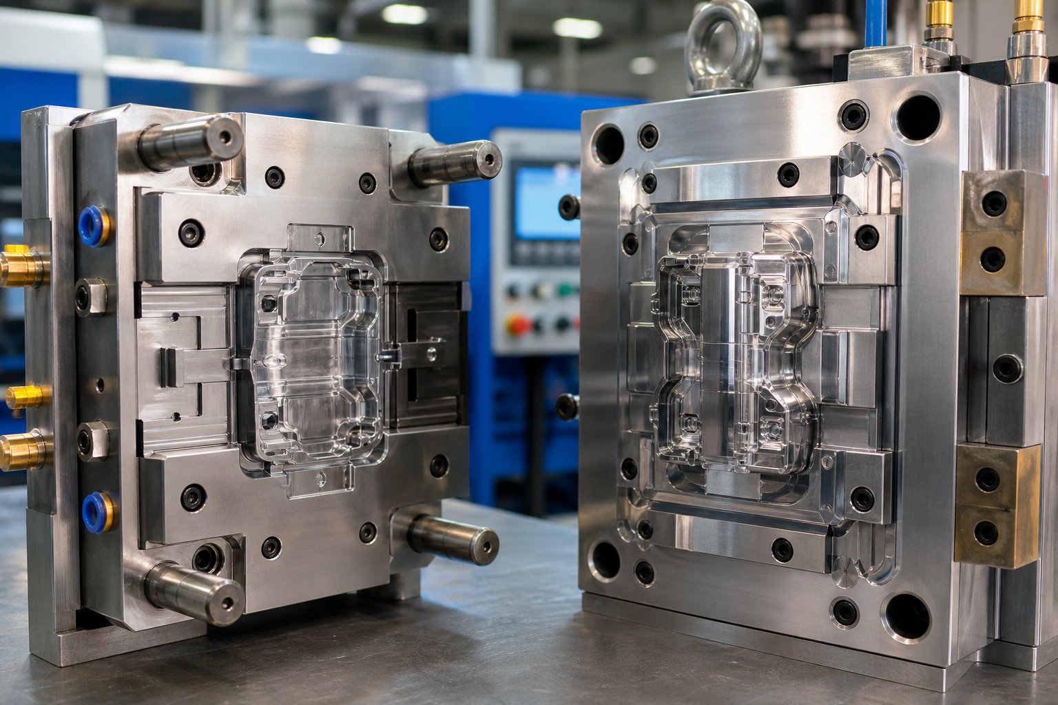
What Injection Molding Parts Really Means
Search for "injection molding parts" and you will land on two very different types of pages. Some explain the physical components inside a mold or machine — cavities, cores, screws, nozzles. Others showcase finished plastic products that roll off a production line. Both interpretations are correct, and that dual meaning is exactly why so many engineers, buyers, and maintenance professionals leave their search feeling only half-informed.
Injection molding is a manufacturing process in which molten plastic material is injected under high pressure into a precision-machined mold cavity, cooled until solid, and then ejected as a finished part — making it the most widely used method for producing high-volume plastic components.
Two Meanings Behind One Search Term
Think of it this way: one meaning lives inside the machine, and the other comes out of it. Injection mold components — the cavity, core, runner system, ejector pins, sprue bushing — are the building blocks that shape every shot of plastic. The injection molded parts that emerge are the end products destined for automotive dashboards, medical devices, or consumer electronics. Whether you work in plastic injection molding or you are sourcing replacement wear items for a production floor, understanding both sides gives you a serious advantage. Engineers design better when they see how each component decision ripples into the finished product. Buyers negotiate smarter when they know why one mold steel or gate type costs more than another. Maintenance teams troubleshoot faster when they can trace a surface defect back to a worn check ring or a plugged vent.
Why Every Component Decision Affects the Final Part
Every element of the injection moulding process is connected. Choose the wrong tool steel and your mold wears prematurely, drifting out of tolerance after a fraction of its expected life. Select an undersized gate and you invite jetting, weld lines, or short shots. Neglect cooling channel layout and warped parts pile up at quality inspection. This article is built around that cause-and-effect philosophy — linking every component choice to a downstream outcome in the plastic molding workflow.
In the sections ahead, you will walk through the complete anatomy of an injection mold, explore the critical machine components that influence melt quality and shot consistency, compare process variants from insert molding to micro-molding, and dive into material selection for mold tooling. From there, the focus shifts to runner and gate design, cooling and defect prevention, real-world industry applications, cost drivers across production volume tiers, and a practical guide to sourcing replacement parts. By the end, you will have a connected understanding of the injection molding of plastics — from the steel that forms the cavity to the finished part that ships to your customer.
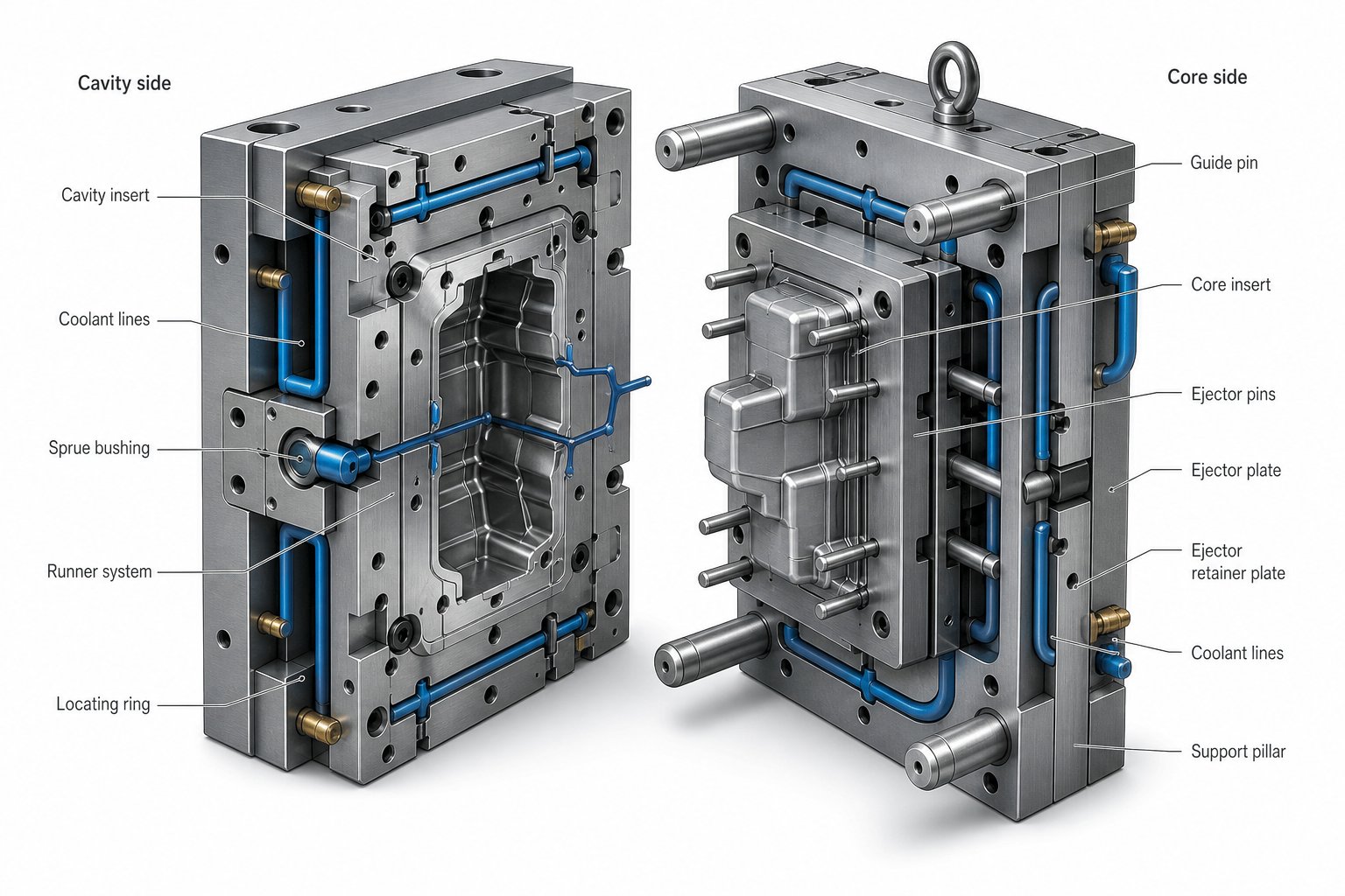
Anatomy of an Injection Mold from Cavity to Ejection
A finished injection molded part is only as good as the mold that shaped it. Every surface detail, dimensional tolerance, and cosmetic finish traces back to specific mold parts working together under extreme pressure and temperature. Understanding the parts of a plastic injection mold — and how each one influences the product that comes out — turns a vague knowledge of the process into a genuine engineering advantage.
The overall mold structure can be broken into three functional systems: the cavity and core that define part geometry, the runner system that delivers molten plastic, and the ejection system that removes the solidified part. Let's look at each one and connect it to the quality of the finished product.
Cavity and Core — Defining Part Geometry
Imagine opening a clamshell. The two halves of an injection mold work in a similar way. The cavity — often called the A-side — is mounted to the stationary platen of the machine. It forms the external surfaces of the part and typically defines the cosmetic or visible side. The core — the B-side — mounts to the moving platen and shapes internal features such as ribs, bosses, and hollow sections.
When the mold closes, these two halves interlock along a boundary known as the parting line. Parting line placement is a critical design decision because it determines where a thin witness line will appear on the finished part. Place it on a cosmetic surface and you create a visible flaw. Place it along a functional edge or hidden seam and it becomes invisible to the end user.
Precision matters here more than almost anywhere else in the mold. The cavity and core are typically machined to tolerances within a few hundredths of a millimeter. Any deviation — from tool wear, thermal expansion, or machining error — translates directly into dimensional inaccuracy in every single part the mold produces. That is why injection mold parts like cavity inserts and core pins are made from hardened tool steels and undergo rigorous quality inspection before assembly.
Runner System and Sprue Components
Molten plastic does not teleport from the machine nozzle into the cavity. It travels through a carefully engineered channel network, and the design of that network directly affects fill balance, cycle time, and material waste.
The journey begins at the sprue bushing — a conical or cylindrical channel that receives molten resin from the injection nozzle and funnels it into the mold. In single-cavity molds, the sprue may feed directly into the gate. In multi-cavity setups, it branches into a primary runner, which then splits into sub-runners that distribute material to each individual cavity.
Runner layout has a direct impact on part quality. If sub-runners are unequal in length or cross-section, some cavities fill faster than others. The result? Parts from one cavity may be fully packed and dimensionally stable, while parts from another cavity show sink marks or short shots. Balanced runner design — where every cavity receives the same volume of material at the same pressure and temperature — is a hallmark of well-engineered mold components.
At the end of each runner channel sits the gate, a small opening that controls how and where material enters the cavity. Gate type and placement influence everything from fill pattern and weld line location to the size of the gate vestige left on the finished part. We will explore gate selection in detail later in this article, but for now, recognize that the runner system is far more than passive plumbing — it is an active quality-control mechanism built into the parts of mold tooling.
Ejection System Components
Once the part has cooled and the mold opens, something has to push the solidified plastic off the core without damaging it. That job falls to the ejection system — and it involves more than simple pins.
The most common approach uses an ejector plate that drives multiple ejector pins forward in a single coordinated stroke. These cylindrical pins apply localized force at predetermined contact points, typically on non-cosmetic surfaces, to release the part. Return pins then reset the system before the mold closes for the next cycle.
However, standard ejector pins are not always the right choice. Part geometry, wall thickness, and surface finish requirements often demand specialized ejection methods. Blade ejectors push against thin ribs without distorting them. Sleeve ejectors wrap around cylindrical cores to distribute pressure evenly across bosses or tubular features. Stripper plates apply uniform force across large flat areas, protecting thin-walled or fragile parts from the concentrated stress a single pin would create. And air ejection uses controlled bursts of compressed air to break adhesion — a valuable technique for textured or highly polished surfaces where any mechanical contact would leave a mark.
Choosing the right ejection method is a design decision that directly affects surface quality and reject rates. The table below provides a practical comparison to guide that choice:
| Ejector Type | Best-Suited Part Geometry | Surface Finish Impact | Complexity Level |
|---|---|---|---|
| Ejector Pins (plate-driven) | General-purpose parts with accessible non-cosmetic surfaces | Leaves small circular witness marks at contact points | Low — standard in most molds |
| Blade Ejectors | Thin ribs, narrow features, or tight spaces | Minimal marks on narrow surfaces; prevents rib distortion | Moderate — fragile blades require precise alignment |
| Sleeve Ejectors | Bosses, deep cylindrical features, tubular sections | Even pressure reduces localized marks; tight tolerances needed to prevent flash | Moderate — requires accurate fit around core |
| Stripper Plates | Flat, thin-walled, or fragile parts with large surface areas | Minimal cosmetic impact; distributes force broadly | High — adds mechanical complexity to mold structure |
| Air Ejection | Delicate, textured, or high-gloss cosmetic parts | No mechanical contact marks; ideal for polish-critical surfaces | Moderate — requires controlled venting paths and timing |
A well-designed ejection system does more than pop a part out of a mold. It preserves the dimensional accuracy and surface integrity that the cavity and core worked so hard to create. When ejection is poorly planned — pins too small, force unevenly distributed, or draft angles insufficient — the results show up as cracked ribs, drag marks, or stress whitening on finished parts.
With the mold's internal anatomy mapped out — from the cavity surfaces that define geometry to the ejection mechanisms that deliver the finished part — the next critical variable is the machine that powers the entire process. The barrel, screw, and clamping unit each introduce their own influence on melt quality and shot-to-shot consistency.
Critical Injection Molding Machine Components That Affect Performance
A flawlessly designed mold can still produce defective parts if the machine feeding it delivers an inconsistent melt. The injection molding machine is the engine behind every cycle, and its internal components — barrel, screw, check ring, nozzle, platens, tie bars — determine whether molten plastic arrives at the cavity at the right temperature, pressure, and volume. When any one of these parts drifts out of specification, the finished product absorbs the consequences.
Understanding the parts of an injection molding machine matters just as much as knowing the mold anatomy covered earlier. Engineers use this knowledge to specify the right equipment for a new project. Maintenance teams rely on it to diagnose production problems before they escalate. Buyers reference it when sourcing replacement injection molding machine parts that keep production lines running.
Injection Unit Components and Their Functions
The injection unit is where raw plastic pellets transform into a homogeneous melt ready for injection. Think of it as the machine's digestive system — material enters as solid granules, gets heated, compressed, mixed, and pushed forward under pressure. Every injection molding machine component in this unit plays a distinct role in melt quality and shot consistency.
- Hopper — Stores and feeds raw plastic pellets into the barrel by gravity. Advanced hoppers include drying systems to remove moisture from hygroscopic resins like nylon or polycarbonate before they enter the melt zone.
- Barrel — A heavy-duty alloy steel cylinder surrounded by heater bands. It serves as the melting chamber where plastic transitions from solid pellets to a uniform molten state across multiple temperature-controlled zones.
- Screw — The workhorse of the injection unit. A reciprocating screw rotates inside the barrel to convey, compress, and mix the material. Its geometry is divided into three functional zones: the feed zone pulls pellets in from the hopper, the compression zone melts and densifies the material through increasing channel depth reduction, and the metering zone homogenizes the melt to a consistent temperature and viscosity before injection.
- Screw Tip — The pointed or contoured end of the screw that makes contact with the melt front during injection. Its geometry affects how cleanly the melt transfers forward and how effectively the check ring seals behind it.
- Check Ring (Non-Return Valve) — Sits at the front of the screw and acts as a one-way valve. During plasticating, it allows molten material to flow past the screw tip into the shot chamber. During injection, it slides back and seals against the screw tip to prevent backflow, ensuring a precise and repeatable shot volume.
- Injection Nozzle — The final passage between the barrel and the mold sprue bushing. It maintains melt temperature and delivers material under high pressure into the mold. Nozzle types include open nozzles for general use, shut-off nozzles that prevent drool between cycles, and reverse taper nozzles for a tighter seal with the sprue.
Each of these injection molding machine components contributes to what industry professionals call melt quality — the uniformity of temperature, viscosity, and pressure across every shot. A screw with worn flights produces an inconsistent melt. A leaking check ring delivers unpredictable shot volumes. A degraded nozzle tip causes drool or material degradation. The downstream defects — dimensional drift, surface blemishes, short shots — almost always trace back to something in this unit.
Clamping Unit and Auxiliary Components
While the injection unit prepares the melt, the clamping unit holds the mold halves together under enormous pressure. Imagine clamping two heavy steel blocks with enough force to resist the hydraulic push of molten plastic trying to separate them — that is the clamping unit's job, and it repeats this thousands of times per production run.
The system centers on two large steel platens. The stationary platen is bolted to the machine frame and holds the cavity side of the mold. The moving platen slides along heavy-duty tie bars — rigid steel rods that guide alignment and absorb the massive clamping force. Tie bar diameter and material grade directly determine the machine's maximum tonnage capacity.
Clamping force itself comes from one of three mechanisms. Hydraulic clamp systems use oil pressure to drive the moving platen forward, offering robust force for heavy-duty applications. Toggle clamp systems employ mechanical linkages that multiply a smaller hydraulic input into rapid, energy-efficient movement — ideal for high-speed production on a plastic molding machine. Electric clamp systems use servo motors for precision positioning, quiet operation, and energy savings up to 70%, making them popular in cleanroom environments and medical manufacturing.
Beyond the platens and clamp mechanism, several auxiliary components keep the injection plastic moulding machine running accurately:
- Heater Bands — Wrapped around the barrel in multiple zones, these electric resistance heaters maintain precise melt temperatures. Even a few degrees of drift can shift viscosity enough to cause fill problems or surface defects.
- Thermocouples — Temperature sensors embedded in each barrel zone and at the nozzle. They provide the real-time feedback that controllers use to regulate heater output. A drifting thermocouple gives false readings, leading operators to chase phantom temperature problems.
- Hydraulic System Components — Pumps, valves, cylinders, and accumulators that power movement in hydraulic and hybrid machines. Contaminated hydraulic oil or worn seals degrade pressure consistency, which shows up as erratic clamp force or uneven injection speed.
Together, the clamping unit and these auxiliary systems ensure that every cycle delivers the same mold closure force, the same melt temperature, and the same injection conditions. When one element falls out of tolerance on a plastics molding machine, the ripple effect reaches the finished part.
Why Machine Parts Wear and When to Replace Them
Every injection molding machine runs in a high-stress environment — extreme temperatures, abrasive fillers, corrosive resins, and repetitive mechanical forces. Over thousands of cycles, even the best-engineered components degrade. The key is recognizing when wear crosses the line from normal to problematic, and acting before it causes reject parts or unplanned downtime.
Here are the most common wear indicators and what they signal:
- Screw and Barrel Wear — Abrasive fillers like glass fiber or mineral additives gradually erode screw flight surfaces and barrel linings. You will notice longer recovery times, inconsistent cushion positions, and visible streaking or poor color mixing in the melt. When the clearance between screw flight and barrel wall grows beyond specification, the screw can no longer build consistent pressure, and shot-to-shot repeatability suffers.
- Check Ring (Non-Return Valve) Wear — A worn check ring fails to seal properly during injection, allowing molten plastic to leak backward past the screw tip. The telltale signs are unstable cushion readings, fluctuating shot weight, and difficulty maintaining pack pressure. This single component, when degraded, undermines the entire injection phase.
- Nozzle Degradation — The nozzle tip endures constant thermal cycling and high-pressure contact with the sprue bushing. Worn nozzle seats cause drool between shots, material leakage, or poor sealing that introduces air into the melt. Cold slugs from a damaged nozzle can block gates and cause short shots.
- Heater Band Failure — Heater bands degrade over time through thermal cycling and physical contact wear. A failed band creates a cold zone on the barrel, producing unmelted pellets or temperature inconsistencies that lead to surface defects and dimensional variation. Checking heater band resistance regularly catches failures before they affect production.
- Thermocouple Drift — Thermocouples lose accuracy gradually, reporting temperatures that diverge from actual barrel conditions. The result is a controller adjusting heater output based on false data — potentially overheating or underheating an entire zone without any visible alarm.
The cost of ignoring these wear signals is steep. A failed check ring can halt a production line mid-run. A degraded heater band creates scrap that goes undetected for hours. Worn screw flights produce dimensional drift that only surfaces during final quality inspection, after hundreds or thousands of parts have already been molded.
Proactive replacement depends on having the right parts available when you need them. Specialized suppliers like NANHAIYA manufacture critical injection moulding machine components — including screw tips, check rings, injection nozzles, heater bands, and thermocouples — to OEM specifications based on drawings, samples, or measured dimensions. For maintenance teams managing multiple machines across a production floor, working with a supplier that can replicate wear parts without requiring original manufacturer involvement significantly reduces lead times and keeps spare parts inventories practical.
Ultimately, every component inside the machine shapes what comes out of the mold. The screw determines melt homogeneity. The check ring governs shot accuracy. The heater bands and thermocouples control the thermal environment. And the clamping unit ensures the mold stays sealed under pressure. These machine-level variables interact directly with the mold components explored earlier — and they also set the stage for how different process types demand different configurations from both the mold and the machine.
Types of Injection Molding Processes and Their Mold Requirements
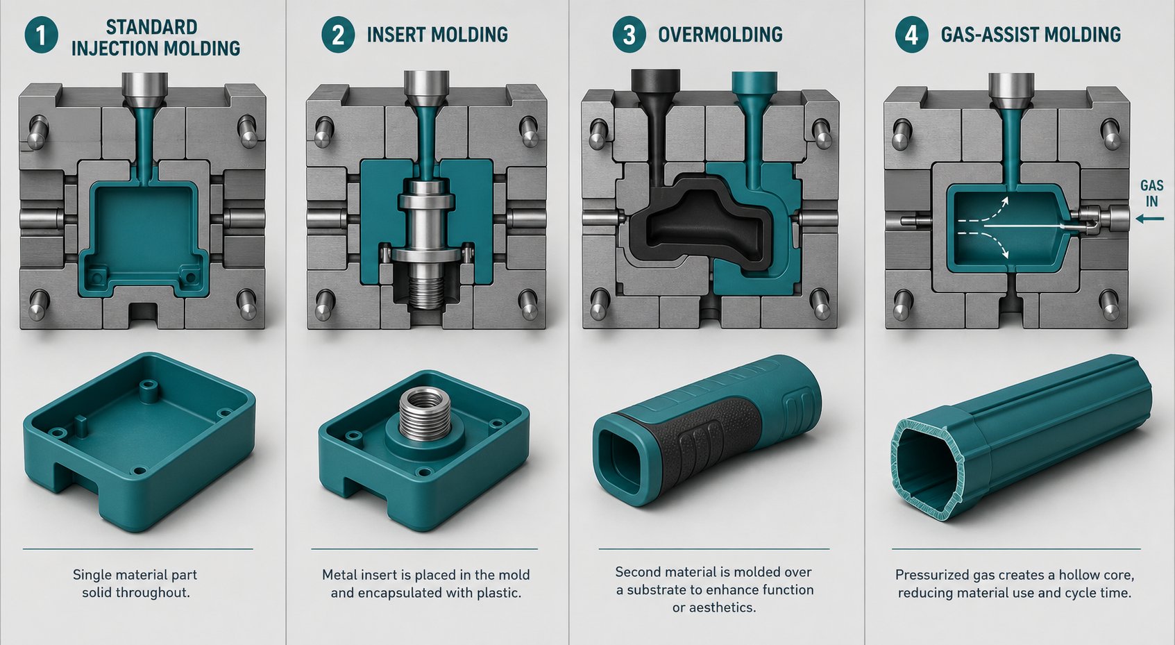
The same machine and many of the same mold components can be reconfigured to run radically different injection molding process variants — each one placing unique demands on cavity geometry, runner layout, nozzle design, and ejection strategy. Choosing a process type is not just an engineering preference; it dictates which mold features you need, how complex the tooling becomes, and ultimately what your finished parts can do.
Standard Injection Molding vs. Insert Molding
Conventional single-material injection molding is the baseline. Pellets melt in the barrel, travel through the nozzle, fill a cavity, cool, and eject. The mold requires a matched cavity and core, a runner system, gates, and an ejection mechanism — all the components covered earlier in this article.
Insert injection molding adds a twist. Before the mold closes, a pre-formed component — typically a metal threaded bushing, electrical contact, or steel pin — is placed into the cavity, either manually or by robotic pick-and-place. Molten plastic then flows around the insert, encapsulating it as it solidifies to form a single integrated part. The insert molding process eliminates post-mold assembly steps like press-fitting or ultrasonic welding, but it changes several mold requirements. Cavity geometry must be modified with recesses or locating features that hold the insert in precise position during injection. Specialized fixtures prevent displacement under high-pressure melt flow. Gate placement also becomes more critical — you need the resin to flow evenly around the insert without creating weld lines in structurally loaded zones or pushing the insert off its seat.
Component injection molding of this kind is common in automotive connectors, medical sensor housings, and aerospace electronics where metal-to-plastic integration must be reliable over thousands of thermal cycles.
Overmolding and Multi-Shot Molding
Where insert molding embeds a foreign object inside plastic, overmolding bonds one plastic over another. A rigid substrate — say, a polycarbonate housing — is molded first, then transferred to a second mold (or a second position within the same mold) where a softer material like a thermoplastic elastomer is injected over it. The result is a multi-material part with a soft-touch grip, an integrated seal, or vibration-dampening properties built right in.
Two-shot and multi-shot molding take this further by using rotating mold platens or core-back mechanisms that expose new cavity surfaces within the same cycle. The mold complexity increases substantially: you need multiple injection units, independent runner systems for each material, and tighter tolerances to align the substrate with the second-shot cavity. Material compatibility also matters — not every polymer pair chemically bonds, so designers must verify adhesion early in development to avoid delamination in the field.
Gas-Assist and Micro-Molding Considerations
Gas-assist injection molding targets parts that are too thick for conventional processing. After the cavity is partially filled with molten plastic — typically 60 to 90 percent of its volume — pressurized nitrogen is injected into the melt core, hollowing out the interior while pushing the remaining plastic against the cavity walls. The gas provides uniform packing pressure from inside the part, eliminating sink marks on thick sections and significantly reducing cycle time compared to solid-wall designs. Mold requirements shift accordingly: gas channels must be designed into the part geometry, nozzle tips or dedicated gas injection points need precise placement, and venting strategies must accommodate both displaced air and gas flow paths.
On the opposite end of the scale, micro-molding focuses on injection molding small parts — think implantable medical components, micro-optics, or miniature electrical connectors weighing fractions of a gram. These tiny parts demand specialized micro-nozzles with extremely small orifice diameters, modified runner designs with minimal volume to prevent material degradation from excessive residence time, and mold venting on a microscale to avoid burn marks in cavities that fill in milliseconds. Even rubber injection molding borrows from these specialized techniques when producing precision elastomeric micro-seals or O-rings with tight tolerances.
The table below summarizes how each process variant reshapes mold requirements, helping you match the right injection molding process to your application:
| Process Type | Description | Typical Applications | Mold Complexity Level | Key Component Differences |
|---|---|---|---|---|
| Standard Injection Molding | Single material injected into a cavity-core mold | General-purpose housings, containers, structural components | Low to Moderate | Standard cavity, core, runner, and ejection systems |
| Insert Molding | Pre-formed metal or plastic insert placed in cavity before injection | Threaded fasteners, electrical connectors, sensor housings | Moderate | Locating fixtures, modified cavity recesses, optimized gate placement around inserts |
| Overmolding / Multi-Shot | Second material molded over a previously molded substrate | Soft-touch grips, sealed enclosures, multi-material handles | High | Multiple injection units, rotating platens or core-back mechanisms, independent runner systems |
| Gas-Assist Molding | Nitrogen gas injected into partially filled cavity to hollow core | Thick handles, structural panels, large housings | Moderate to High | Gas channels in part design, specialized gas nozzle tips, tailored venting for gas flow |
| Micro-Molding | Extremely small precision parts molded with specialized equipment | Implantable medical devices, micro-optics, miniature connectors | High | Micro-nozzles, ultra-low-volume runners, microscale venting, high-precision cavity inserts |
Each of these process variants reshapes the demands placed on injection molding complex parts — but process selection alone does not guarantee mold longevity or part quality. The steel grade you choose for the cavity, core, and wear surfaces determines how well the mold holds up across tens of thousands or millions of cycles, especially when processing abrasive or corrosive resins.
Mold Component Material Selection and Its Impact on Production
A plastic injection mold is only as durable as the steel — or aluminum — it is machined from. You can design a perfect cavity geometry, balance every runner channel, and specify the ideal gate type, yet none of it matters if the mold material cannot withstand the temperatures, pressures, and abrasive forces of your chosen resin over the expected production run. Material selection for injection mold tooling is the decision that connects tooling investment to long-term part cost, surface quality, and production uptime.
Sounds straightforward? In practice, the trade-offs between hardness, corrosion resistance, machinability, and cost create a decision matrix that trips up even experienced teams. The following breakdown gives you a clear framework for matching the right material to your project requirements — whether you are building a quick prototype tool or a multi-million-cycle production mold.
Tool Steel Grades Compared for Mold Components
Five material options cover the vast majority of injection molding tooling decisions. Each one occupies a specific niche defined by its hardness, wear characteristics, and suitability for different production volumes and resin types.
- P20 (Pre-Hardened Alloy Steel) — The most widely used mold steel in the industry. P20 arrives from the supplier already hardened to approximately 28–32 HRC, which means it can be machined directly without post-machining heat treatment. It is affordable, easy to cut, and well-suited for low- to moderate-volume production. The trade-off is limited wear resistance — P20 struggles with abrasive glass-filled resins and will not hold up over millions of cycles.
- H13 (Hot-Work Tool Steel) — The go-to choice for high-volume injection molds. H13 is heat-treated after machining to reach 48–52 HRC, giving it excellent toughness, heat resistance, and dimensional stability under rapid thermal cycling. It handles engineering-grade resins like ABS, polycarbonate, and nylon well and resists the thermal fatigue cracking that destroys softer steels in demanding production schedules. The main drawback is that H13 lacks inherent corrosion resistance and costs more than P20 upfront.
- S7 (Shock-Resistant Tool Steel) — A specialized steel with outstanding impact resistance, reaching 54–58 HRC. S7 is chosen for mold components that endure repeated mechanical shock — think complex tools with moving slides, lifters, or collapsing cores that slam together every cycle. It is harder to machine than most alternatives, but it excels where toughness under impact is the primary concern.
- S136 (Stainless Mold Steel) — The premium choice for corrosion resistance and polishability. S136 contains high chromium content that prevents rust and pitting, even when processing corrosive resins like PVC or flame-retardant compounds that release acidic gases during molding. It achieves 48–54 HRC after heat treatment and can be polished to a near-mirror finish, making it essential for medical device molds, optical parts, and food-contact packaging. S136 carries the highest material cost, but the reduced maintenance and superior surface quality often justify the investment over the life of the tool.
- Aluminum (7075 or QC-7) — Not a steel at all, but an increasingly popular option for prototype and short-run tooling for injection moulding. Aluminum molds machine several times faster than steel, offer excellent thermal conductivity for rapid cooling, and cost a fraction of hardened steel tooling. The limitation is durability — aluminum is too soft for high-volume production or abrasive resins, and cavity surfaces can degrade after only a few thousand shots.
The table below compares these injection molding materials across the key selection criteria, giving you a side-by-side view of where each option fits:
| Material | Hardness (HRC Range) | Wear Resistance | Corrosion Resistance | Production Volume Suitability | Relative Cost Tier |
|---|---|---|---|---|---|
| P20 | 28–32 | Low to Moderate | Low — susceptible to rust in humid environments | Up to ~100,000 shots for simple parts | Low |
| H13 | 48–52 | High — resists abrasive fillers well | Low to Moderate — not stainless | 500,000 to 1,000,000+ shots | Medium-High |
| S7 | 54–58 | High — excellent under impact loading | Low — requires surface treatment in corrosive applications | 500,000+ shots in high-impact mold actions | Medium-High |
| S136 | 48–54 | High — with superior polish retention | Excellent — resists acidic off-gassing and humidity | 1,000,000+ shots; ideal for corrosive resins | High |
| Aluminum (7075) | N/A (Brinell ~150) | Low — soft surface wears quickly | Moderate — naturally oxidizes but not corrosion-proof | Hundreds to low thousands of shots | Very Low |
Matching Material to Production Volume and Resin Type
Production volume is the single biggest factor steering your material decision, but resin chemistry is a close second. Here is how the two interact across common tooling tiers:
Prototype tooling targets short runs — a few hundred to a few thousand parts — where speed to first article and low upfront cost are the priorities. Aluminum and soft P20 dominate here. You can have a functional aluminum mold machined and sampling parts in a fraction of the time required for a hardened steel tool. The cavities will wear, but they only need to survive long enough to validate part design and material selection before committing to production-grade plastic injection molds.
Bridge tooling fills the gap between prototype and full production, typically covering runs in the tens of thousands. Hardened P20 or H13 in a single-cavity or low-cavity configuration strikes the right balance. These injection mould tools deliver repeatable quality over a meaningful run without the cost of a fully hardened, multi-cavity production mold. Bridge tooling is especially valuable when market demand is uncertain — you invest enough to serve current orders while preserving the option to build a larger tool if volumes grow.
Production tooling is engineered for hundreds of thousands to millions of cycles. Hardened H13 and S136 are the standard choices, often in multi-cavity configurations with hot runner systems. At these volumes, every fraction of a second shaved from cycle time and every rejected part avoided compounds into significant cost savings — and only premium injection molding tooling materials can sustain that level of performance.
Resin type overlays an additional constraint regardless of volume. Abrasive glass-filled nylons and mineral-filled polypropylenes act like liquid sandpaper against cavity surfaces. Even moderate production runs with these materials demand harder steels — H13 at minimum, or S7 for components exposed to the worst abrasion. Corrosive resins such as PVC, POM (acetal), and flame-retardant ABS release acidic gases during processing that attack unprotected steel surfaces, causing pitting and surface degradation that transfers directly to the molded part. For these applications, S136 or 420 stainless provides the chromium-rich barrier needed to maintain surface integrity across the mold's full service life.
How Material Choice Drives Mold Longevity and Part Cost
It is tempting to minimize upfront tooling cost by selecting a softer, less expensive mold steel. On a purchase order, the savings look attractive. In production, the math often tells a different story.
A lower-grade steel wears faster, which means cavity dimensions drift sooner. Parts that measured within tolerance at shot 10,000 may start drifting at shot 50,000. By shot 100,000, you are either running out-of-spec product, investing in cavity repair, or replacing the mold entirely. Each of those outcomes adds cost — in scrap, in downtime, and in the engineering time required to requalify a repaired or replacement tool.
Premium plastic injection molds built from hardened H13 or S136 cost more at the outset, but they hold tolerances far longer, require less frequent maintenance, and keep production lines running without interruption. When you calculate total cost of ownership — mold purchase price plus maintenance cost plus scrap cost plus downtime, all divided by total parts produced — the per-part cost on a premium tool is almost always lower for mid-to-high-volume projects.
Consider cooling efficiency as another hidden cost driver. Aluminum transfers heat faster than any mold steel, so aluminum prototype molds cycle quickly despite their limited lifespan. Among steels, H13 offers better thermal conductivity than S136, which means H13 molds can achieve shorter cycle times under identical cooling configurations. A two-second cycle time advantage across a million parts translates to hundreds of hours of saved machine time — a real economic impact that originates entirely from material selection.
The bottom line: choosing injection molding materials for your mold is not a simple cost comparison on a spec sheet. It is a lifecycle calculation that weighs upfront investment against wear rate, maintenance frequency, resin compatibility, and cumulative part cost. Get it right, and the mold pays for itself many times over. Get it wrong, and the savings you thought you captured at the purchase stage evaporate on the production floor.
Material grade sets the foundation for how long a mold lasts — but it does not control how efficiently plastic flows into the cavity or how cleanly it separates from the runner after each cycle. Those outcomes depend on a different set of design decisions: runner configuration and gate type selection.
Runner Systems and Gate Types That Control Part Quality
Steel grade determines how long a mold lasts, but the runner system and gate design determine how well it performs on every single shot. These two elements of injection mold design control the path molten plastic travels from the machine nozzle to the cavity wall — and any misstep along that path shows up as a defect on the finished part. If you study an injection molding diagram of any production tool, you will notice the runner layout and gate positioning receive as much engineering attention as the cavity itself. There is a good reason for that.
Hot Runner vs. Cold Runner Trade-Off Analysis
The first major decision in injection molding mold design is whether to use a hot runner or a cold runner system. Each approach has loyal advocates, and both are widely used across different types of molds in injection molding. The right choice depends on your production volume, resin type, part complexity, and tolerance for maintenance overhead.
A cold runner system is the simpler of the two. Molten plastic flows through unheated channels — the sprue, runners, and gates — that solidify along with the part each cycle. The solidified runner is ejected, separated from the part, and either discarded or reground for reuse. Cold runners dominate prototype work, short production runs, and applications using thermally sensitive resins that degrade under prolonged heat exposure. Their tooling is straightforward and comparatively inexpensive to build, maintain, and repair.
A hot runner system keeps the entire runner channel at melt temperature using heated manifolds and electrically controlled nozzles. The plastic never solidifies inside the runner, so there is zero runner scrap. Material savings alone can be substantial — especially with expensive engineering resins like PEEK, liquid crystal polymers, or medical-grade polycarbonates. Hot runners also shorten cycle times by eliminating the cooling phase for solidified runners. The trade-off is significantly higher upfront tooling cost, added complexity from heater bands and thermocouples embedded in the manifold, and greater maintenance demands when a heating element or temperature sensor fails mid-production.
The table below lays out the key decision factors side by side so you can evaluate which system fits your injection molding tool design requirements:
| Decision Factor | Hot Runner System | Cold Runner System |
|---|---|---|
| Upfront Tooling Cost | High — manifold, heated nozzles, controllers add significant expense | Low — simple channels machined directly into mold plates |
| Material Waste | Near zero — no solidified runner to discard or regrind | High — runner scrap generated every cycle; regrind adds handling cost |
| Cycle Time Impact | Shorter — no runner cooling phase; faster overall cycle | Longer — runner must cool and solidify before ejection |
| Maintenance Complexity | High — heater bands, thermocouples, and nozzle tips require regular inspection and replacement | Low — minimal components to maintain; easier color and material changes |
| Resin Suitability | Best for thermally stable resins; not ideal for heat-sensitive materials like PVC or certain flame-retardant compounds | Suitable for nearly all resins, including thermally sensitive and shear-sensitive polymers |
| Production Volume Threshold | Becomes cost-effective at medium-to-high volumes where material savings and faster cycles offset tooling investment | Most economical for prototyping, short runs, and frequent material or color changes |
One nuance worth highlighting: hot runner systems require precise thermal control at every nozzle and manifold zone. A single failed heater band can freeze a gate, starving one cavity in a multi-cavity mold while the others continue to fill. That imbalance produces a mix of good parts and rejects in the same shot — a quality nightmare that demands immediate intervention. Cold runners, by contrast, fail more gracefully. Their simplicity is their greatest insurance policy against complex thermal failures.
Gate Types and How to Choose the Right One
The gate is the final restriction point between the runner channel and the mold cavity. Its size, shape, and placement influence fill pattern, packing efficiency, cosmetic appearance, and even the structural integrity of the finished part. Choosing the right gate type is one of the highest-impact decisions in plastic injection mold design — and getting it wrong is one of the most expensive mistakes to correct after a mold is built.
Here are the most common gate types, along with the selection criteria that should guide your choice:
- Edge Gate — The most straightforward and widely used gate style in injection molding design. The gate sits along the parting line and feeds material directly into the cavity wall. Edge gates are easy to machine, provide excellent packing control for medium- to thick-walled parts, and accommodate a wide range of resins. The downside is a visible gate vestige on the parting line edge that requires secondary trimming. Edge gates are typically sized at 50 to 80 percent of the injected wall thickness to balance fill rate with clean separation.
- Submarine (Tunnel) Gate — A self-degating design where the gate tunnels below the parting line surface and shears automatically during ejection. This eliminates manual gate trimming, making tunnel gates ideal for high-volume automated production. They work best with flexible or semi-crystalline resins that can withstand the shearing force without fracturing. Brittle materials risk leaving rough vestiges or cracking at the gate location. Gate tip diameters generally range from 40 to 70 percent of wall thickness, depending on the material and packing requirements.
- Pin-Point Gate — Used primarily in three-plate cold runner molds, pin-point gates offer small, clean gate vestiges that are barely visible on the part surface. They are well-suited for thin-walled or symmetrical parts like cups, caps, and small enclosures. The small diameter — typically 0.5 to 1.0 mm — means they freeze off quickly, limiting packing time. This makes them best for parts where short cycles and cosmetic surfaces outweigh the need for heavy packing.
- Fan Gate — A wide, flat gate that spreads material across a broad section of the cavity wall, creating a uniform flow front. Fan gates are the preferred choice for flat, wide parts like panels or trays where unidirectional flow reduces warpage and minimizes weld lines. The trade-off is a large gate vestige that requires trimming and often leaves a visible mark along the part edge.
- Cashew (Banana) Gate — A curved variation of the tunnel gate designed to place the injection point on a hidden surface — typically the underside or interior of a part. Cashew gates are strictly limited to tough, ductile plastics because the curved runner must flex and deform during ejection without breaking. Glass-filled or mineral-reinforced materials cannot be used with this gate style. When cosmetic requirements demand a completely invisible gate location, cashew gates deliver — at the cost of higher mold complexity and tighter material constraints.
How Runner and Gate Design Influence Part Quality
Every runner dimension and gate specification feeds directly into part quality — and the consequences of poor decisions are often not visible until production is underway. Here is how these design choices cascade into real-world defects:
Imbalanced runners cause short shots and dimensional inconsistency. In a multi-cavity mold, runners that differ in length or cross-section deliver unequal volumes of material to each cavity. Some cavities fill and pack completely while others are starved. The result is a tray of parts where some meet spec and others show sink marks, voids, or incomplete fill. Naturally balanced runner layouts — where every flow path from sprue to gate is geometrically identical — are the standard solution, though even balanced layouts can develop imbalances from shear-induced temperature variations in the melt.
Oversized gates leave cosmetic blemishes and extend cycle time. A gate that is larger than necessary takes longer to freeze off, which delays the point at which the part can be ejected. It also leaves a larger vestige — a raised or rough mark on the part surface that may require secondary trimming or polishing. On cosmetic parts, an oversized gate can be a rejection criterion all by itself.
Undersized gates cause jetting, high shear, and material degradation. When the gate cross-section is too small, material accelerates through the restriction like water through a pinched hose. This can create jetting — a condition where a thin stream of plastic shoots into the cavity and folds on itself rather than forming a smooth flow front. The high shear rates generated in an undersized gate can also damage reinforcing fibers, degrade polymer chains, and elevate material temperature beyond its processing window, leading to splay marks, discoloration, or reduced mechanical properties in the finished part.
Poor gate placement creates weld lines in critical zones. When the melt front splits around a core or feature and reconverges, it forms a weld line — a visible seam where two flow fronts meet but do not fully bond. Gate placement determines where these weld lines land. Placing the gate so that flow fronts merge in a structurally loaded area can reduce part strength by 10 to 50 percent depending on the material and processing conditions.
The takeaway is straightforward: runner layout and gate selection are not secondary details to finalize after cavity geometry is locked in. They are core elements of injection molding design that directly determine whether a mold produces parts that pass inspection or parts that fill a scrap bin. Every decision made at this stage — runner diameter, gate type, gate size, gate location — echoes through cycle time, surface quality, dimensional accuracy, and mechanical performance.
Getting the runner and gate right ensures material arrives at the cavity under ideal conditions. What happens after it gets there — how quickly and evenly it cools, and how trapped air escapes — introduces an entirely different set of component decisions that are just as consequential for final part quality.
Cooling Design and Defect Prevention Through Better Components
Material arrives at the cavity under ideal conditions — the runner delivered it at the right pressure, and the gate shaped its flow front. What happens next determines whether you pull a dimensionally stable part from the mold or send a warped reject to the scrap bin. Cooling accounts for 66 to 75 percent of the total injection molding cycle time, making it the single largest contributor to both productivity and part quality. Yet cooling system design remains one of the most overlooked aspects of mold engineering — especially when injection molding large parts where uneven temperature distribution magnifies every thermal imbalance.
Cooling Channel Design and Conformal Cooling
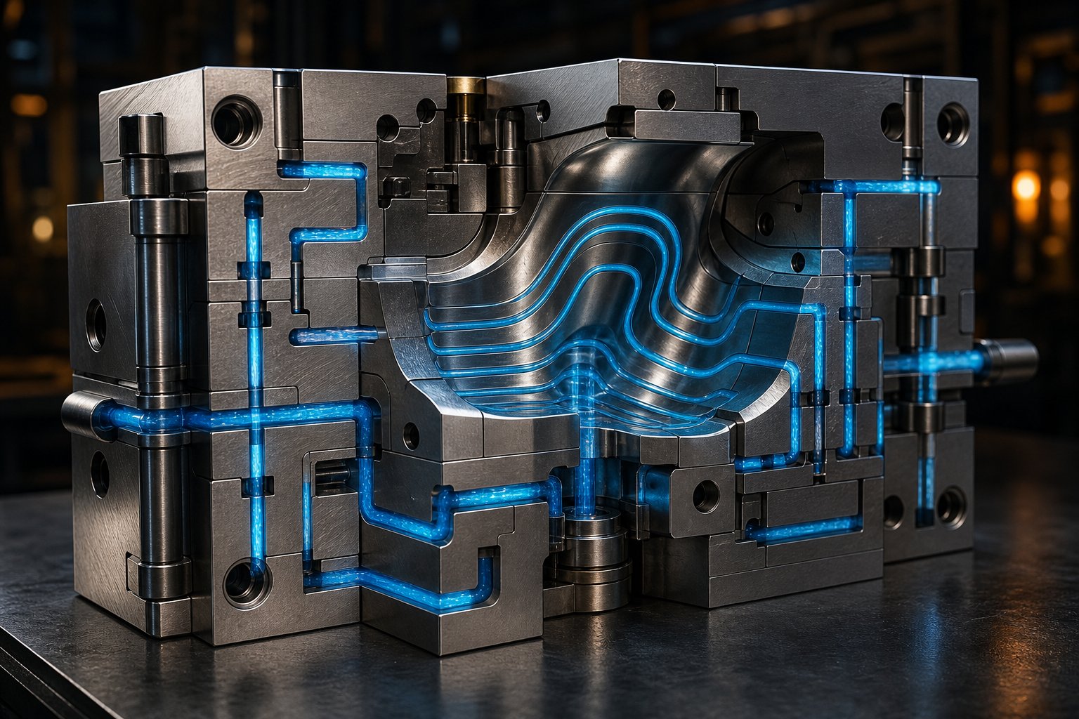
Every injection mold is essentially a heat exchanger. Hot molten plastic enters the cavity, and a network of cooling channels circulating water or oil extracts that heat until the part solidifies enough for ejection. The faster and more uniformly this happens, the shorter the cycle and the better the dimensional accuracy of the finished part.
Straight-drilled cooling channels are the conventional approach. As the name implies, these are straight holes drilled or milled through the mold plates, arranged in series or parallel configurations. Series connections — where multiple channels link end to end from inlet to outlet — are most common because they maintain consistent turbulent flow throughout the circuit. Turbulent flow transfers heat far more efficiently than laminar flow, which is why maintaining adequate flow rate through properly sized channels matters so much.
For parts with simple geometry, straight-line channels provide adequate uniform cooling. Complex shapes create a different challenge. Deep cores, tall bosses, and areas far from any straight channel path become thermal hot spots that cool slower than surrounding regions. Three supplemental components address this gap:
- Bubblers — Small tubes inserted into deep areas of the mold that bring coolant flow to regions a straight channel cannot reach, ensuring more uniform heat extraction in tall core pins or deep pockets.
- Baffles — Thin metal inserts placed inside a drilled channel that redirect coolant flow upward through one side and back down the other, effectively doubling the cooling surface area within a single bore.
- Thermal pins — Sealed components filled with a phase-change fluid that absorbs heat from the mold by vaporizing, then releases it when cooled by passing coolant — useful in areas too tight for conventional waterlines.
Conformal cooling channels represent a significant advancement. Unlike straight-drilled lines constrained to linear paths, conformal channels follow the contour of the part surface, maintaining a nearly constant distance to the cavity wall throughout the entire geometry. The result is dramatically more uniform heat extraction — eliminating the hot spots that cause differential shrinkage and warping in large injection molded parts.
The catch? Conformal channels are nearly impossible to machine using conventional methods. They are produced through metal 3D printing (laser sintering or direct metal laser melting), where layers as thin as 40 micrometers are built up to create complex internal geometries that no drill bit could ever reach. The technology adds cost to mold fabrication, but for high-volume production tools — especially those producing injection molded plastic parts with tight dimensional requirements — the cycle time reduction and quality improvement often deliver a strong return on investment.
When choosing between approaches, consider part geometry complexity, production volume, and tolerance requirements. Simple parts with uniform wall thickness often perform well with properly positioned straight-drilled channels. Parts with complex curves, varying wall thicknesses, or critical dimensional zones — common in large part injection molding for automotive panels or structural housings — benefit enormously from conformal cooling technology.
Common Injection Molding Defects Linked to Component Issues
Cooling is only one piece of the defect prevention puzzle. Every injection molding defect traces back to a specific component condition — a worn surface, an undersized channel, an improper temperature, or a missing feature. Recognizing these root causes is what separates reactive troubleshooting from proactive prevention when producing injection molding plastic parts at scale.
The table below connects the most common defects to their component-level origins and the strategies that prevent them:
| Defect Name | Root Cause (Mold or Machine Component) | Prevention Strategy |
|---|---|---|
| Sink Marks | Insufficient cooling at thick sections; inadequate packing pressure from worn check ring or undersized gate | Optimize cooling channel placement near thick walls; maintain check ring seal integrity; ensure adequate gate size for packing |
| Warping | Uneven cooling across the part — one side cools faster than the other due to asymmetric channel layout or mold material thermal differences | Design symmetrical cooling circuits for both mold halves; use conformal channels for complex geometries; maintain uniform mold temperature |
| Flash | Worn parting line surfaces that no longer seal cleanly; insufficient clamp tonnage; excessive injection pressure forced by poor venting | Inspect and re-surface parting lines regularly; verify clamp force exceeds projected cavity area requirements; improve venting to reduce required fill pressure |
| Short Shots | Undersized gates restricting flow; low injection pressure from worn screw or check ring; trapped air blocking cavity fill | Verify gate dimensions match material flow requirements; replace worn injection unit components; add venting at end-of-fill locations |
| Weld Lines | Poor gate placement causing flow fronts to split and reconverge in critical areas; insufficient venting at flow-front meeting points | Relocate gates to push weld lines into non-structural, non-cosmetic zones; add vents where flow fronts converge; consider sequential valve gating |
| Burn Marks | Insufficient venting — trapped air compresses and superheats during filling, scorching the resin at end-of-fill locations | Add or deepen vents at last-fill areas; clean blocked vents during maintenance; reduce injection speed if venting cannot be immediately modified |
Notice a pattern? Several of these defects — short shots, burn marks, flash — can stem from the same overlooked mold feature: venting. When trapped air has nowhere to escape, operators compensate by increasing injection pressure or speed, which then triggers flash or material degradation elsewhere. One under-vented region can create a cascade of symptoms that appear to be three separate problems.
This is particularly critical when plastic molding large parts. Bigger cavities trap more air volume, flow paths are longer, and the last-fill areas are farther from the gate — all factors that amplify venting-related defects. What might cause a minor cosmetic blemish on a small part can become a structural failure mode on a large housing or panel.
Venting as an Overlooked Mold Component
Imagine filling a bottle with water while keeping the cap on. The trapped air resists the incoming liquid, slowing the fill and creating turbulence. The same physics apply inside a mold cavity. Every shot begins with air already occupying the cavity space. As molten plastic enters, that air must escape cleanly — or it compresses, heats, and fights the incoming melt.
Vent channels are shallow machined slots — typically cut along the parting line — that provide a controlled escape path for displaced air and gases generated by the heated resin. The critical dimensions are:
- Vent depth — Must be shallow enough to allow gas escape while preventing molten plastic from entering. Typical depths range from 0.01 to 0.05 mm depending on the resin. Crystalline materials like nylon or polyethylene require shallower vents due to lower viscosity, while amorphous materials like ABS or polycarbonate tolerate slightly deeper channels.
- Vent width — Wider vents evacuate air faster. Standard practice uses widths of 3 to 12 mm depending on part size and fill rate. Multiple narrow vents often outperform a single wide channel because they distribute evacuation across more of the cavity perimeter.
- Vent land length — The shallow portion of the vent extends only 1 to 3 mm before opening into a deeper relief channel that routes gas to atmosphere. This short land prevents plastic from flowing far enough to create flash while still providing adequate gas flow.
Placement strategy matters as much as dimensions. Vents belong at the last areas to fill — which means you need to understand your melt flow pattern before specifying vent locations. End-of-fill regions, deep rib tips, corners where flow fronts converge, and areas opposite the gate are the highest-priority locations. In multi-cavity molds producing injection molded plastic parts, each cavity needs its own venting plan because slight runner imbalances can shift fill patterns between cavities.
Beyond parting line vents, experienced mold designers employ additional venting strategies for challenging geometries. Ejector pin clearances can serve as secondary vent paths — the small gap between a pin and its bore allows gas to escape from deep pockets. Sintered metal vent inserts — porous steel plugs pressed into the mold — evacuate air from areas impossible to reach with conventional machined vents, such as the bottom of deep blind ribs or enclosed boss features.
The real danger of inadequate venting is not just a single defect type — it is process instability. As mold development experts note, a part may short-shot in one cycle, burn in the same area the next, and then flash elsewhere once settings are pushed harder to compensate. All three symptoms trace back to the same root cause: the cavity is not breathing properly. Addressing venting at the design stage — rather than chasing symptoms during trials — prevents this cascade and makes the entire process more robust.
Cooling uniformity and venting adequacy are universal concerns across every injection molding application. Yet the specific tolerances, mold materials, and component configurations required to address them vary dramatically depending on the industry you serve — from automotive structural panels running glass-filled nylon to micro-molded medical implants demanding mirror-polished S136 cavities.
Industry Applications That Shape Mold and Part Requirements
A mold designed for a disposable food container and a mold designed for a surgical instrument housing share the same basic anatomy — cavity, core, runner, ejection system. Yet the materials, tolerances, surface finishes, and component configurations could not be more different. Industry requirements dictate which earlier design decisions matter most, turning the general principles covered so far into very specific engineering choices. Here is how three major sectors — automotive, medical, and consumer electronics and packaging — reshape what injection molding parts look like from both the tooling side and the finished product side.
Automotive Injection Molding Demands
Automotive injection molding operates at a scale and intensity that pushes mold components to their limits. A single vehicle can contain hundreds of plastic parts — dashboard panels, bumper covers, headlight housings, HVAC ducts, engine covers, fuse boxes, and battery trays — and production programs routinely call for millions of identical units over the life of a platform. That volume demands molds built from hardened tool steels like H13 or S136, rated for well over a million cycles without dimensional drift.
Resin selection adds another layer of severity. Automotive injection applications frequently specify glass-filled nylon for under-hood structural brackets, polypropylene for interior trim, and PC/ABS blends for instrument cluster housings that need both heat resistance and impact strength. Glass-filled resins, as discussed in the material selection chapter, behave like liquid sandpaper — abrasive fibers scour cavity surfaces with every shot, accelerating wear on gates, runners, and cavity walls. Multi-cavity mold configurations compound this challenge because they multiply the number of surfaces under attack in each cycle while simultaneously increasing output.
Tolerances in automotive injection molding are tight. Snap-fit clips, locating tabs, and assembly features must align within a millimeter on the vehicle assembly line. That precision depends on hardened cavity inserts, robust cooling systems that prevent warpage, and preventive maintenance schedules that catch parting line wear before it degrades dimensional accuracy. As one industry truism puts it: on an automotive assembly line, consistency is not optional — a single dimensional deviation can halt production downstream.
Medical Device and Precision Component Requirements
If automotive molding is about volume and durability, precision injection molding for medical devices is about cleanliness, traceability, and micron-level accuracy. Injection moulding medical applications include diagnostic cartridges, microfluidic lab-on-a-chip devices, surgical instrument handles, implantable components, and single-use consumables like pipette tips and test vials.
Mold material selection takes on a different priority here. Corrosion-resistant stainless steels — S136 (Stavax ESR) or 420 stainless (1.2083) — dominate because medical injection molding parts demand ultra-clean cavity surfaces that resist pitting from sterilization agents and cleanroom disinfectants. Any surface degradation transfers directly to the molded part, potentially compromising biocompatibility or optical clarity in diagnostic components. Beryllium copper alloy inserts also appear frequently in medical mold designs — their high thermal conductivity reduces cycle times in thick-walled parts without sacrificing dimensional stability.
Injection molding machines for medical components typically operate in ISO Class 7 or Class 8 cleanrooms. The mold itself must withstand frequent cleaning protocols without corrosion or polish loss. Process validation under ISO 13485 adds documentation requirements that go far beyond standard manufacturing — every shot, every temperature reading, and every dimensional measurement must be traceable. Specialized mold components for micro-molding implantable parts push these demands even further, requiring cavity inserts machined to micron-level tolerances, ultra-low-volume runners to prevent material degradation from excessive residence time, and microscale venting to avoid burn marks in cavities that fill in milliseconds.
Consumer Electronics and Packaging Applications
Consumer electronics and packaging occupy the opposite end of the aesthetic spectrum from medical devices — but they bring their own intense component demands. Think about the glossy housing on a smartphone, the perfectly smooth bezel on a laptop screen, or the crystal-clear lid on a premium food container. Every one of those plastic injection components started with a mold cavity polished to SPI A1 or A2 mirror finish, using cavity steels like S136 that hold that polish across hundreds of thousands of cycles.
High-gloss cosmetic finishes require not only premium cavity materials but also meticulous venting, perfectly balanced filling, and precise temperature control. Even minor defects — a faint flow mark, a barely visible weld line, a tiny gate vestige in the wrong location — become rejection criteria on consumer electronics housings where brand perception rides on surface quality.
Packaging applications shift the emphasis from cosmetics to speed and material efficiency. Thin-wall injection molding for food containers, lids, and cups demands high-speed injection units that fill extremely thin cavities — often below 1 mm wall thickness — before the material freezes mid-flow. High injection speeds, elevated melt temperatures, and optimized gating are essential to prevent short shots and maintain consistent wall distribution. Hot runner systems dominate in high-volume packaging because they eliminate runner scrap entirely, saving significant material cost across runs that can reach tens of millions of parts per year.
The table below compares how these three industry sectors shape mold and part requirements across the key decision variables discussed throughout this article:
| Industry | Typical Resin Types | Production Volume Range | Critical Mold Material | Key Component Considerations | Tolerance Requirements |
|---|---|---|---|---|---|
| Automotive | Glass-filled nylon, polypropylene, PC/ABS blends, ABS | Hundreds of thousands to millions | Hardened H13 or S136 | Multi-cavity molds; wear-resistant gates and runners; robust cooling for warpage control | Tight — typically +/- 0.1 to 0.2 mm for assembly-critical features |
| Medical Devices | Medical-grade polycarbonate, PEEK, COC/COP, polypropylene | Thousands to millions (consumables) | S136 / Stavax ESR, 420 stainless, beryllium copper inserts | Cleanroom-compatible surfaces; micro-molding cavity inserts; validated processes under ISO 13485 | Very tight — micron-level for microfluidic and implantable parts |
| Consumer Electronics and Packaging | ABS, polycarbonate, PMMA, HDPE, polypropylene | Hundreds of thousands to tens of millions | S136 for cosmetic cavities; H13 for structural components | Mirror-polished cavities; hot runner systems for material savings; high-speed injection units for thin-wall parts | Moderate to tight — cosmetic standards often stricter than dimensional specs |
Each industry proves the same fundamental point: the mold components and machine configurations you choose are not generic decisions. They are responses to specific performance demands — volume, surface finish, resin behavior, regulatory compliance — that vary dramatically from one application to the next. And behind every one of these tooling decisions sits another question that ultimately drives the business case: what does it all cost, and how do production volume tiers change the math?
Cost Drivers and Production Volume Decisions for Molded Parts
Automotive molds built from hardened H13, medical tooling machined from mirror-polished S136, high-speed packaging tools running tens of millions of thin-wall cycles — every industry application demands a different combination of components, materials, and complexity. Yet one question ties them all together: how much does the tooling cost, and how does that investment translate into the price of each injection molded part that rolls off the line?
Budgeting for injection molding tooling is not a single line-item exercise. It is a lifecycle calculation where upfront mold investment, production volume, cycle efficiency, and per-shot material consumption interact in ways that can make a seemingly expensive mold the cheapest option — or turn a bargain tool into a money pit. Understanding these cost drivers gives engineers, buyers, and project managers the framework to make tooling decisions that align with business reality.
What Drives Injection Molding Tooling Costs
Why does one mold cost a few thousand dollars while another exceeds six figures? The gap comes down to five primary cost drivers that compound on top of each other:
- Part Complexity — This is the single largest variable. A simple open-and-shut mold with no undercuts, slides, or lifters requires straightforward cavity machining and minimal assembly. Add a single undercut and the tool needs a sliding side-action. Add an internal thread and you introduce an unscrewing mechanism. Each additional mold action — slides, lifters, collapsing cores, rotating inserts — adds engineering design time, precision machining, and assembly complexity. Complex part designs with intricate geometries demand correspondingly complex molds, and the cost scales accordingly.
- Cavity Count — A single-cavity mold produces one part per cycle. A four-cavity mold produces four. An eight-cavity mold produces eight. Every additional cavity multiplies the machining, polishing, and fitting work required — plus it demands a larger mold base, a bigger machine with higher clamp tonnage, and a more carefully balanced runner system. The upfront cost increases substantially, but the per-part production cost drops because every cycle yields more output.
- Mold Steel Grade — As explored in the material selection chapter, aluminum prototype molds cost a fraction of hardened H13 or S136 production tools. The steel itself is more expensive per kilogram, it takes longer to machine, and it often requires heat treatment, EDM, and skilled hand-finishing that softer materials do not. A simple aluminum prototype mold can start around $3,000, while a multi-cavity hardened steel production mold can exceed $100,000 — a cost ratio driven almost entirely by material choice and the machining it demands.
- Surface Finish Requirements — A standard textured finish is relatively quick and inexpensive to apply. A high-gloss SPI-A1 mirror polish, on the other hand, requires specific cavity steels, hours of skilled manual polishing labor, and careful handling throughout the build. Tighter cosmetic tolerances push costs upward even when part geometry is otherwise simple.
- Hot Runner Inclusion — Adding a hot runner system introduces a heated manifold, electrically controlled nozzle tips, thermocouples, and a temperature controller — all integrated into the mold structure. This can add a significant percentage to the base mold cost. For short runs, the added investment rarely pays back. For high-volume production of plastic injection molding parts, the material savings and cycle time reductions often justify the premium within the first few months of production.
These five factors do not operate in isolation. A complex, multi-cavity, hot-runner mold built from S136 with a mirror finish sits at the top of the cost spectrum. A simple, single-cavity, cold-runner aluminum mold with a standard texture sits at the bottom. Most real-world projects land somewhere in between, and the skill lies in choosing the combination that delivers the lowest total cost for your specific production scenario — not just the cheapest mold on the purchase order.
Production Volume Tiers and Tooling Strategy
Imagine buying a race car to drive to the grocery store. That is essentially what happens when a team invests in a fully hardened, multi-cavity production mold for a product that will only sell a few thousand units. The reverse mistake is just as costly — building a soft aluminum tool for a product that needs half a million parts, then watching it wear out and require replacement after a fraction of that volume.
Matching your tooling tier to your production volume is one of the highest-leverage decisions in the entire injection moulding plastic parts workflow. Industry practice defines three distinct tiers, each with its own sweet spot:
Prototype tooling (Class 5) covers production volumes from a few hundred to a few thousand parts. These tools are built from aluminum or soft, pre-hardened steel using simplified mold configurations — cut-in-steel cores and cavities without interchangeable inserts, minimal or no cooling channels, and simple cold runner systems. The goal is speed to first article and low upfront cost. Prototype molds let you validate part geometry, test material behavior, and gauge market demand before committing serious capital. The trade-off is limited durability — expect a lifespan measured in hundreds to low thousands of shots.
Bridge tooling (Class 3 to Class 4) serves the gap between prototype validation and full-scale production, typically covering tens of thousands of parts. Bridge molds use harder steels — P20 or pre-hardened H13 — in single- or low-cavity configurations. They deliver repeatable quality over a meaningful run without the cost and lead time of a fully hardened production tool. Class 4 tools using mild steel can reach approximately 100,000 shots, while Class 3 tools with hardened steel push toward 500,000. Bridge tooling is especially strategic when market demand is uncertain — you invest enough to fulfill current orders while preserving the option to scale up.
Production tooling (Class 1 to Class 2) is engineered for hundreds of thousands to millions of cycles. These molds use fully hardened steels — H13 or S136 heat-treated to a minimum of 48 HRC — with multi-cavity layouts, hot runner systems, conformal cooling, and all the component sophistication discussed throughout this article. Class 1 tools can exceed a million cycles, making them the workhorse behind high-volume molded products in automotive, medical, and consumer packaging industries.
Choosing the right tier is not just about volume. It is a strategic decision that balances risk, timeline, and economics. Here is a practical decision framework:
- Define your total lifetime volume estimate. Be realistic — include best-case, expected, and worst-case scenarios. A product expected to sell 500 units does not justify production-grade tooling, even if you hope it eventually reaches a million.
- Assess your design maturity. If the part geometry might change based on testing, customer feedback, or regulatory review, start with prototype tooling. Locking in expensive production steel before the design is frozen risks costly mold modifications or a complete rebuild.
- Evaluate your resin requirements. Abrasive glass-filled or corrosive resins accelerate tool wear, which means even moderate production volumes may demand harder steels than the volume alone would suggest.
- Calculate the per-part cost at each tier. A more expensive mold with higher cavitation and a faster cycle often delivers a lower cost per plastic injection molded part than a cheaper single-cavity tool running at half the output rate. Run the math before committing.
- Factor in lead time and market timing. A prototype or bridge tool can be ready in weeks; a full production mold may take months. If speed to market matters more than per-part cost at launch, start with a bridge tool and transition to production tooling once demand is proven.
The single-cavity vs. multi-cavity trade-off deserves special attention within this framework. A single-cavity mold is cheaper and faster to build, but it produces one part per cycle. A four-cavity mold costs roughly two to three times more — not four times, because the mold base and runner system share infrastructure — yet it quadruples output per cycle. For high-volume injection moulded parts, the math almost always favors multi-cavity tools because the per-part amortization of the higher mold cost is offset many times over by the increased production efficiency.
Calculating Per-Part Cost Variables
The mold investment is only half the equation. Every cycle generates ongoing production costs that accumulate across every molded component you ship. Understanding these variables — and how the component choices discussed throughout this article cascade into per-part economics — turns cost estimation from guesswork into a structured calculation.
The total cost of each plastic injection molding part breaks down into five core variables:
- Mold amortization — Divide the total mold cost by the expected lifetime production volume. A $50,000 mold producing 500,000 parts adds $0.10 per part. The same mold producing only 10,000 parts adds $5.00. This single variable explains why production volume is the dominant factor in injection molding economics — as volume increases, the mold cost per part becomes minimal.
- Material cost per shot — Calculate the weight of the part plus any runner scrap (in a cold runner system) and multiply by the resin price per kilogram. Hot runner systems eliminate runner scrap, reducing material consumption per shot. Expensive engineering resins like PEEK or medical-grade polycarbonate make this variable a significant portion of per-part cost, while commodity resins like polypropylene keep it minimal.
- Machine time cost — Divide the cycle time by the number of cavities to determine machine seconds per part, then multiply by the machine hourly rate. This is where cycle time optimization — through better cooling design, appropriate runner sizing, and efficient gate selection — directly reduces cost. A two-second cycle time reduction across a million parts saves hundreds of machine hours.
- Labor and overhead allocation — Operator time for press monitoring, part inspection, packing, plus allocated factory overhead per machine hour. Automation — robotic part removal, vision inspection, automated packing — reduces direct labor cost per part, especially at higher volumes where the investment in automation equipment is amortized across more units.
- Secondary operations — Any post-molding steps such as gate trimming, assembly, pad printing, painting, or specialized packaging add incremental cost. Self-degating designs (tunnel or submarine gates) eliminate manual trimming labor. Insert molding reduces post-mold assembly steps. Every component-level design decision that eliminates a secondary operation reduces the per-part cost downstream.
Here is the critical insight: every component decision made earlier in this article feeds directly into these five cost variables. Choosing a hot runner over a cold runner reduces material cost per shot but increases mold amortization. Selecting conformal cooling channels shortens cycle time — lowering machine time cost — but adds to the upfront mold investment. Specifying a multi-cavity layout multiplies mold cost but divides machine time per part. Picking the right mold steel extends tool life, which lowers amortization per part by spreading the investment across more total shots.
The teams that consistently deliver competitive injection molded part pricing are not the ones who minimize any single cost variable in isolation. They are the ones who optimize across all five simultaneously — balancing mold investment, cycle efficiency, material usage, labor, and secondary operations into the lowest sustainable total cost per part for their specific volume and quality requirements.
Cost modeling tells you what to invest. The remaining challenge is protecting that investment — keeping molds and machines running at peak performance through strategic sourcing of replacement parts and disciplined preventive maintenance.
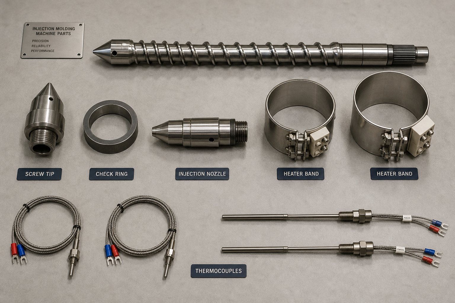
Sourcing Replacement Parts and Maintaining Production Equipment
A perfectly optimized cost model means nothing if a worn check ring shuts down your press at 2 a.m. on a Wednesday. Every dollar invested in mold steel selection, runner design, cooling optimization, and multi-cavity tooling delivers returns only as long as the equipment keeps running. Yet across many injection molding facilities, spare parts management and preventive maintenance remain reactive — teams scramble to source a replacement nozzle tip or heater band after a failure, absorbing days of unplanned downtime that could have been prevented with a few hundred dollars of inventory sitting on a shelf.
This final section closes the lifecycle loop by connecting every component discussed throughout this article to a practical strategy for keeping injection mold equipment and machines in production-ready condition.
Building a Replacement Parts Strategy for Production Uptime
Imagine your highest-output press goes down because a check ring failed mid-shift. The part is not on your shelf. Your OEM supplier quotes a four-week lead time. Meanwhile, that press sits idle — no parts shipping, no revenue flowing, and downstream assembly lines waiting on components that are not coming. This scenario plays out in facilities around the world, and it is almost always preventable.
The solution starts with identifying which injection machine parts are most likely to fail and which failures cause the most production disruption. Not every component carries the same risk. A hydraulic hose fitting that takes ten minutes to replace from local stock is a different category of risk than a custom screw tip that requires international sourcing. Maintenance teams should map each critical wear component against two variables: failure frequency (how often it wears out under normal production conditions) and downtime impact (how long the machine sits idle if the part is not immediately available).
Components that score high on both dimensions — frequent wear and severe downtime consequences — belong in your on-site spare parts inventory. Based on the wear patterns identified by industry procurement specialists, here are the essential spare parts categories every injection molding facility should stock:
- Screw tips and check rings (non-return valves) — These are the most failure-prone components in the injection unit. A worn check ring causes unstable shot weight, cushion drift, and packing inconsistency that produces scrap for hours before anyone identifies the root cause.
- Injection nozzles and nozzle tips — Thermal cycling and high-pressure contact with the sprue bushing degrade nozzle seats over time. Worn nozzles cause drool, cold slugs, and material leakage that contaminate shots.
- Heater bands (mica and ceramic) — These electric resistance heaters endure constant thermal cycling and physical wear. A failed band creates a cold zone on the barrel, producing unmelted material and temperature inconsistencies that cascade into surface defects and dimensional drift.
- Thermocouples — Temperature sensors that gradually lose accuracy, causing controllers to regulate heater output based on false readings. Stocking replacements for every barrel zone and the nozzle prevents phantom temperature problems from persisting across shifts.
- Ejector pins and return springs — Mechanical components inside the mold that experience thousands of impact cycles per day. Scoring, mushrooming, or binding in ejector pins causes drag marks and part sticking. Return springs weaken over time and should be replaced preventively.
- O-rings, seals, and hydraulic components — Hydraulic cylinder seals, valve seals, and cooling circuit O-rings degrade from heat exposure and chemical contact. A single failed seal can cause hydraulic leaks that compromise clamp force or create oil contamination near the mold.
- Guide pins and bushings — Alignment components that wear from repeated mold open-close cycles. Galling or uneven wear on guide surfaces leads to mold misalignment, flash on parting lines, and accelerated wear on cavity and core surfaces.
The depth of your inventory should reflect lead times and machine criticality. A press running three shifts on a high-priority automotive program justifies a deeper spare parts buffer than a press running intermittent prototype jobs. As a rule of thumb, stock enough high-frequency consumables — screw tips, check rings, nozzles, heater bands, and thermocouples — to cover at least one complete replacement cycle for every active machine, with replenishment orders triggered well before stock reaches zero.
How to Source Custom and OEM-Equivalent Components
Knowing what to stock is half the challenge. The other half is finding a supplier who can deliver the right part, to the right specification, without the lead times and pricing premiums that make proactive inventory management impractical.
Three sourcing approaches dominate the market for molding machine parts and injection moulding equipment components, each with distinct trade-offs:
Custom manufacturers specializing in OEM-equivalent parts offer the best balance of cost, flexibility, and lead time for most facilities. Companies like NANHAIYA manufacture replacement components — screw tips, check rings, injection nozzles, heater bands, thermocouples, die heads, pelletizing blades, screen packs, filter adapters, and gearbox-related components — based on drawings, samples, photos, or measured dimensions. This approach is especially valuable when original equipment is aging, when the OEM no longer supports a specific model, or when you need parts faster than the original manufacturer can deliver. A specialized supplier that reverse-engineers from your existing component ensures dimensional and metallurgical accuracy without requiring you to navigate the OEM's procurement bureaucracy. For maintenance teams and plant buyers managing fleets of plastic injection machine parts across multiple press brands and vintages, this flexibility is a significant operational advantage.
OEM direct sourcing provides guaranteed compatibility and full traceability to the original machine specifications. The downside is cost and lead time. OEM parts often carry premium pricing — sometimes two to three times the cost of an equivalent custom-manufactured component — and delivery timelines can stretch to weeks or months, especially for older machine models or international orders. OEM sourcing makes the most sense for warranty-covered equipment, for components where exact firmware or electrical integration is critical (servo drives, PLCs, proprietary controllers), or when regulatory requirements mandate original manufacturer documentation.
Aftermarket suppliers offer generic replacement parts at competitive prices with faster availability than most OEMs. The risk is quality variability. Without rigorous technical vetting, aftermarket parts may arrive with dimensional inaccuracies, inferior material grades, or heat treatment inconsistencies that cause premature failure. If you go the aftermarket route, insist on material certifications, hardness test reports, and dimensional verification before installing any component in a production machine.
The smartest procurement strategies combine all three approaches. Use custom manufacturers like NANHAIYA for high-frequency wear items where cost savings and lead time reductions have the biggest impact. Reserve OEM sourcing for proprietary electronic and control system components. And evaluate aftermarket options only when supported by verifiable quality documentation. This blended approach keeps injection moulding machine parts inventory practical, affordable, and reliable.
Preventive Maintenance Schedules for Mold and Machine Components
Stocking the right parts is a prerequisite. Using them proactively — before failures occur — is what actually protects production uptime. A structured preventive maintenance program tied to actual usage rather than calendar dates ensures that inspections and replacements happen when they matter, not on an arbitrary schedule that may be too early for one machine and too late for another.
Industry maintenance frameworks recommend structuring injection mold maintenance around shot-count tiers rather than fixed time intervals, because mold wear is driven by cycles, not by days on the calendar. A mold running 50,000 shots per month needs attention far more frequently than one running 5,000. Here is a practical maintenance framework adapted from proven industry practices:
Every production run (pre-run and post-run checks):
- Inspect cavity surfaces for scratches, dents, or material buildup that could transfer to part surfaces.
- Check parting line faces for flash residue or visible damage — worn parting surfaces are a primary cause of flash defects discussed earlier in this article.
- Verify ejector pins retract flush and operate smoothly without binding or sticking.
- Inspect sprue bushing and nozzle seat for wear or drool marks.
- Confirm cooling line connections are secure with no visible leaks, and verify flow rates match baseline readings.
- Check mold vents for resin buildup or blockage — clogged vents cause burn marks and incomplete fills.
Every 50,000 shots (routine preventive maintenance):
- Clean all vent channels and verify gas escape paths are clear.
- Inspect ejector pins for scoring, mushrooming, or signs of misalignment.
- Lubricate all moving components — slides, lifters, leader pins — per OEM specifications.
- Compare cooling channel flow rates to documented baseline values to catch early scale buildup.
- Check all O-rings and seals for compression set or deterioration.
- Test hot runner zones for temperature consistency and response time.
Every 150,000 shots (intermediate maintenance):
- Measure vent depth against original specifications — vents shallow out over time from parting line compression.
- Polish cavity and core surfaces to restore original finish grade.
- Descale cooling channels and verify restored flow capacity — as covered earlier, cooling accounts for roughly 60 percent of cycle time, and even thin scale layers degrade thermal performance.
- Measure critical cavity dimensions against original tolerance drawings to detect drift before it produces out-of-spec parts.
- Replace ejector return springs regardless of visible condition — spring fatigue is invisible until it causes a mold crash.
Every 300,000 shots (major overhaul):
- Fully disassemble the mold and clean all components individually.
- Measure all core and cavity steel against original OEM dimensions and evaluate components beyond tolerance for rebuild or replacement.
- Probe cooling channels for blockage, internal corrosion, or wall thinning.
- Replace all wear items — pins, springs, seals, guide bushings — regardless of visible condition.
- Recertify hot runner systems including heaters, thermocouples, and wiring integrity.
- Perform a first-article inspection after reassembly before releasing the mold back to production.
Machine-side maintenance (ongoing):
- Check heater band resistance regularly across all barrel zones and the nozzle. A reading outside normal range indicates a band approaching failure — replace it before it creates a cold zone.
- Monitor screw and barrel wear by tracking recovery time, cushion consistency, and melt quality. Gradual degradation in these indicators signals increasing clearance between screw flights and barrel wall.
- Inspect check ring function by monitoring shot weight consistency. Fluctuating cushion readings or unstable pack pressure are early warnings of a check ring that no longer seals properly.
- Verify thermocouple accuracy periodically using a calibrated reference sensor. A drifting thermocouple can send the controller chasing temperature targets that do not reflect actual barrel conditions.
- Inspect tie bars for even stretch during clamping and check platen parallelism against machine OEM specification.
The connection between this maintenance framework and every earlier chapter is direct. The defects covered in the cooling and venting section — sink marks, warping, flash, burn marks — are the exact symptoms that preventive maintenance prevents. The mold materials discussed in the tooling chapter determine how many shots you can run between inspections. The machine components explored in the injection unit section — screws, check rings, nozzles, heater bands — are the same items that belong in your spare parts inventory and on your maintenance checklist.
Injection molding equipment delivers its best results when every element — from mold design through machine configuration to ongoing maintenance — operates as an integrated system. A worn cavity surface degrades part quality. A failing heater band shifts melt temperature. A clogged vent causes burn marks. A depleted spare parts shelf turns a minor component swap into a week of lost production. The facilities that achieve the highest uptime, lowest scrap rates, and most competitive per-part costs are the ones that treat sourcing, maintenance, and production as a continuous loop — not separate departments operating in isolation.
Frequently Asked Questions About Injection Molding Parts
1. What are the main parts of an injection mold?
An injection mold consists of three core functional systems. The cavity (A-side) and core (B-side) define the part geometry and meet along the parting line. The runner system — including the sprue bushing, primary runner, sub-runners, and gates — delivers molten plastic from the machine nozzle into the cavity. The ejection system uses components like ejector pins, blade ejectors, sleeve ejectors, stripper plates, or air ejection to remove the solidified part without damaging its surface. Supporting elements such as guide pins, bushings, cooling channels, and vent slots round out the mold structure and directly influence part quality, cycle time, and mold longevity.
2. How do you choose the right mold steel for injection molding?
Mold steel selection depends on three primary factors: production volume, resin type, and surface finish requirements. For prototype runs under a few thousand shots, aluminum or soft P20 steel offers fast machining and low cost. Mid-volume bridge tooling typically uses hardened P20 or H13 for durability up to 500,000 cycles. High-volume production molds require fully hardened H13 or S136, especially when processing abrasive glass-filled resins or corrosive compounds like PVC. S136 stainless steel is the premium choice for medical and optical molds that demand mirror-polish retention and corrosion resistance. Always weigh total cost of ownership — cheaper steel may lower upfront cost but increase per-part expense through faster wear and more frequent maintenance.
3. What causes common defects in injection molded parts?
Most injection molding defects trace directly to specific mold or machine component issues. Sink marks result from insufficient cooling near thick wall sections or a worn check ring that cannot maintain adequate packing pressure. Warping occurs when cooling channels are asymmetrically positioned, causing one side of the part to shrink faster than the other. Flash appears when parting line surfaces wear or clamp tonnage is insufficient. Short shots stem from undersized gates, low injection pressure, or trapped air blocking cavity fill. Burn marks indicate inadequate venting — trapped air compresses and superheats during filling. Addressing these root causes at the component level, rather than adjusting process settings alone, delivers more stable and lasting solutions.
4. When should you replace wear parts on an injection molding machine?
Replace injection molding machine wear parts based on measurable performance indicators rather than fixed time intervals. A check ring needs replacement when cushion readings become unstable or shot weight fluctuates beyond acceptable tolerance. Screw and barrel replacement is warranted when recovery time increases, color mixing deteriorates, or the clearance between screw flights and barrel wall exceeds OEM specifications. Nozzle tips should be swapped when drool between shots, cold slugs, or material leakage appear. Heater bands require replacement when resistance readings fall outside normal range or a barrel zone fails to reach target temperature. Specialized suppliers like NANHAIYA manufacture these components to OEM specifications from drawings, samples, or measured dimensions, enabling faster turnaround than original equipment manufacturers.
5. What is the difference between hot runner and cold runner systems in injection molding?
Cold runner systems use unheated channels where plastic solidifies each cycle alongside the part, producing runner scrap that is either discarded or reground. They are simpler, cheaper to build, easier to maintain, and suitable for prototyping, short runs, and thermally sensitive resins. Hot runner systems keep runners at melt temperature using heated manifolds and electrically controlled nozzles, eliminating runner waste entirely. They shorten cycle times and save significant material cost on expensive engineering resins. However, hot runners add substantial upfront tooling cost, require embedded heater bands and thermocouples for thermal control, and demand more maintenance. Hot runners typically become cost-effective at medium-to-high production volumes where material savings and faster cycles offset the higher initial investment.
Written by
Nanhaiya Technical Team
Zhoushan Nanhaiya Plastic Machinery Co., Ltd.
The Nanhaiya technical team supports screw and barrel manufacturing projects through application review, technical communication, custom manufacturing coordination, and production and quality control.
Discuss Your Application
Related Articles
More insights on screw barrel technology and plastics processing.

What Nobody Tells You About Screw Barrel For Plastic Machine Design
Oct 10, 2026
Learn how screw barrel for plastic machine design affects melt quality, throughput, and wear life. Covers geometry, resin matching, troubleshooting, and sourcing.
Read Article
Single Screw Extruder for Sheet: Stop Guessing, Start Specifying
Oct 9, 2026
Learn how to specify a single screw extruder for sheet production. Covers screw geometry, resin-specific processing, troubleshooting, and maintenance best practices.
Read Article
PE Pipe Extruder Machine: What Datasheets Won't Tell You
Oct 9, 2026
Learn how a PE pipe extruder machine works, key specs explained, material grade selection, maintenance tips, and buyer guidance beyond the datasheet.
Read ArticleLooking for something else?
Search by material, symptom or product and jump straight to the relevant page.
These are navigation suggestions based on keyword matching — not a quotation, not a delivery commitment, and not a substitute for engineering review. Final specification is confirmed by our engineers against your drawings and processed material.
Need help with screw barrel selection?
Share your machine model, processed material and application. Our team can help with pricing and technical support.