

What Is the Injection Molding Barrel and Screw System
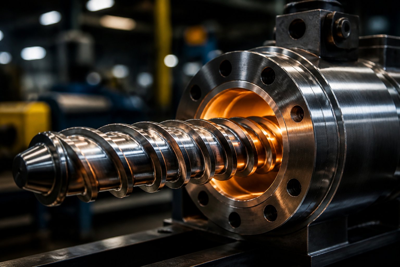
When you hear someone refer to the "screw" or the "barrel" of an injection molding machine, it is tempting to think of them as separate spare parts sitting on different shelves. In reality, the injection molding barrel and screw function as a single, tightly integrated plasticizing system. The barrel provides a heated cylindrical chamber, and the screw rotates inside it to convey, compress, melt, and homogenize raw polymer pellets before they are injected into the mold. Neither component can deliver a quality melt on its own. Together, they form the engine that drives every shot your machine produces.
The injection molding barrel and screw form the plasticizing unit — the heart of every injection molding machine — responsible for converting raw polymer pellets into a homogeneous melt ready for injection.
This article goes well beyond surface-level descriptions. You will find detailed coverage of screw geometry, barrel construction and liner materials, the metallurgy behind wear resistance, resin-to-screw matching strategies, temperature control methods, defect troubleshooting traced back to the plasticizing unit, and a complete maintenance framework. If you manage, operate, or specify injection molding equipment, this is the resource that connects every dot between these two components and the parts they help you produce.
What the Barrel and Screw Actually Do
Imagine dropping solid plastic pellets into a machine and expecting a perfectly uniform, bubble-free melt to emerge at the other end. That transformation happens across three distinct functional stages inside the plasticizing unit:
- Solids conveying (feed zone): Pellets drop from the hopper into deep screw channels that grip and push them forward along the barrel. At this stage, the material is still solid, and consistent feeding is the priority. As Aprios notes, the screw and barrel assembly sits at the heart of the injection unit, playing a key role in conveying and melting plastic pellets from the very first moment they enter the system.
- Melting and compression (transition zone): The screw channels gradually become shallower, squeezing the pellets against the heated barrel wall. This combination of mechanical shear and conducted heat transforms solid granules into a viscous melt. Too much compression risks burning the resin; too little leaves unmelted particles behind.
- Metering (pumping zone): The shallowest channel section stabilizes temperature and pressure so the melt reaching the screw tip is uniform in viscosity and temperature. This consistency is what keeps shot weights stable and defects low cycle after cycle.
Each zone depends on the one before it. A feed zone that starves the compression zone produces an inconsistent melt, and a metering zone cannot fix what upstream zones failed to plasticize properly.
Why a Systems-Level Perspective Matters
Here is a scenario that plays out in molding shops more often than it should: a maintenance team replaces a worn screw with a high-quality unit, yet melt quality barely improves. Why? Because the barrel bore has worn beyond its permissible tolerance, and the enlarged clearance between the screw flight outer diameter and the barrel inner wall allows melt to leak backward instead of moving forward. The gap between the screw flights and barrel wall is a critical performance parameter — when it grows beyond roughly 0.2 to 0.3 mm, output and quality decline significantly.
The lesson is straightforward: barrel bore tolerances, heating zone configuration, and screw flight geometry must be specified and maintained in concert. A mismatch degrades melt quality regardless of how good each component is individually. The barrel's heating zones need to complement the screw's compression profile. The bore concentricity must align with the screw's outer diameter. The feed throat cooling must work in harmony with the first heating zone. Treating one component as excellent while ignoring its partner is like tuning only half an engine — the performance ceiling drops immediately.
That interdependence is exactly why the rest of this article examines every element of the plasticizing system as a connected whole, starting with the detailed anatomy of the screw itself.
Injection Screw Anatomy and Design Parameters
Every injection screw looks like a simple helical shaft at first glance. Look closer, and you will find that its geometry is precisely engineered to transform solid pellets into a uniform melt across three carefully proportioned zones. The depth of each flight, the rate at which channels taper, and the overall proportions of the screw dictate plasticization quality, throughput, and energy consumption. Understanding these details is what separates a well-specified plasticizing system from one that fights you on every cycle.
The Three Functional Zones of an Injection Screw
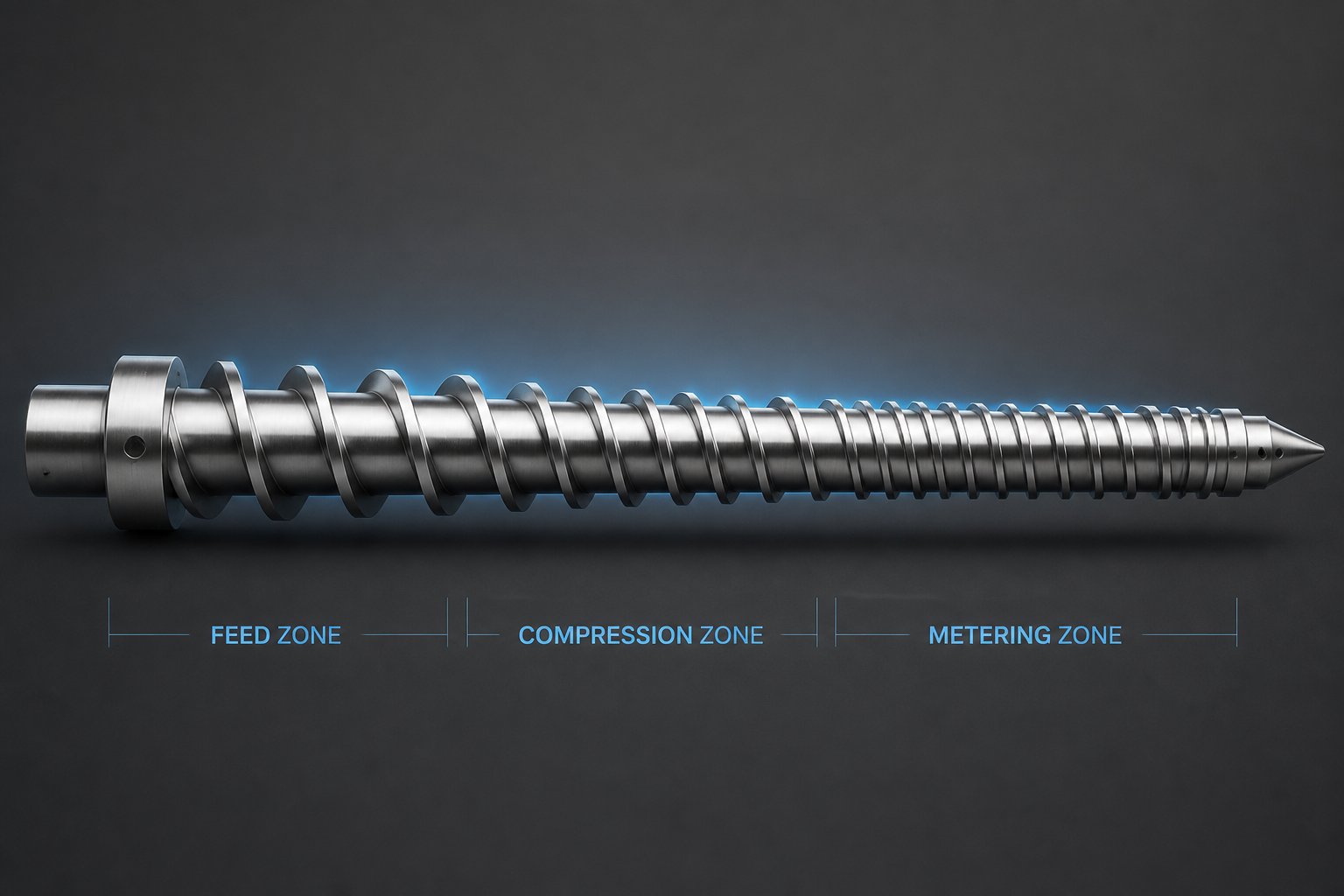
The injection molding screw feed, compression, and metering zones each perform a distinct role in the plasticization process. Think of them as three stages of a relay race — each one must execute flawlessly and hand off smoothly to the next.
The feed zone sits directly beneath the hopper opening. Its flights are the deepest on the entire screw, creating large channels that accept solid pellets and push them forward. Consistent solids conveying here prevents starved feeding and shot-to-shot variation downstream. Typically, the feed zone occupies roughly 50% of the total flighted length on a general-purpose screw.
The compression (transition) zone is where the real transformation begins. Flight depth decreases progressively, squeezing pellets against the heated barrel wall. This compaction generates significant shear-friction heat while expelling trapped air back toward the feed throat. The rate at which channel depth decreases — gradual or aggressive — directly impacts how much mechanical energy the resin absorbs and how quickly it melts.
The metering zone features the shallowest flights on the screw. Its job is to deliver a homogeneous, thermally uniform melt at a consistent pressure to the screw tip. Flight depth remains constant through this section, acting as a precision pump that stabilizes output. Without an adequately sized metering zone, you will see temperature variation in the melt and inconsistent fill patterns in the cavity.
| Zone | Primary Function | Typical Flight Depth | Role in Plasticization |
|---|---|---|---|
| Feed | Solids conveying | Deepest (largest channel volume) | Accepts pellets from the hopper and moves them forward; consistent intake prevents downstream starvation |
| Compression (Transition) | Melting and compaction | Progressively decreasing | Generates shear heat and pressure; compresses pellets against barrel wall to accelerate melting and expel air |
| Metering | Melt homogenization and pumping | Shallowest (constant depth) | Stabilizes melt temperature, pressure, and viscosity for consistent shot delivery to the screw tip |
Critical Screw Design Parameters
Selecting a screw is not just about picking one that fits the barrel bore. Several design parameters control how the screw interacts with the resin, and each one influences the quality of your final parts.
L/D ratio — the ratio of the screw's flighted length to its nominal outer diameter — is one of the first specifications you will encounter. Common values for injection molding screws are 20:1, 22:1, and 24:1. A higher L/D ratio for injection molding screw design means the resin spends more time in the barrel, giving it more opportunity for uniform melting and mixing. As Essentra Components explains, a larger L/D ratio generates more shear heat uniformly, improves melt homogeneity, and increases residence time — potentially enabling faster cycles or larger shots. Most injection molding machines ship with a 20:1 screw, but resin families with demanding melt-quality requirements often benefit from 24:1 or longer.
Compression ratio — the ratio of the feed-zone channel depth to the metering-zone channel depth — determines how aggressively the screw compacts and shears the resin. Imagine you are squeezing toothpaste from a tube: a higher compression ratio applies more force over a shorter distance. A screw with a 2.0:1 compression ratio applies far less shear than one at 3.5:1. When compression ratio increases, so does the shear heat imparted to the resin, the heat uniformity of the melt, the energy consumption, and the potential for creating stresses in sensitive materials. Choosing the right compression ratio depends heavily on the polymer being processed — a topic covered in detail in the resin-matching section later in this article.
Helix angle refers to the angle of the screw flight relative to a plane perpendicular to the screw axis. Most standard injection screws use a helix angle of approximately 17.66 degrees (equivalent to a square pitch, where the pitch equals the screw diameter). Adjusting the helix angle changes the conveying efficiency and the amount of shear applied to the resin. A steeper angle can improve solids conveying in certain applications, while a shallower angle increases residence time.
Flight width — the thickness of the helical ridge measured along the screw axis — affects both structural integrity and flow dynamics. Wider flights are more durable and resist wear from abrasive fillers, but they reduce the available channel area for resin flow. Narrow flights maximize throughput capacity but wear faster when processing glass-filled or mineral-filled compounds. The flight width also influences the shear rate at the barrel wall, making it another variable that must be balanced against the resin's sensitivity to mechanical energy.
None of these parameters operates in isolation. A screw with a high compression ratio and a short L/D, for example, generates intense shear over a brief residence time — ideal for some semi-crystalline resins but potentially catastrophic for heat-sensitive materials like PVC. Every parameter must be tuned as part of an integrated design.
Screw Tip and Check Valve Assembly
At the front end of the screw sits one of the most critical — and most frequently overlooked — components in the plasticizing system: the non-return valve, commonly called the check ring. This small assembly acts as a one-way gate. During screw rotation (recovery), molten plastic flows through the valve to accumulate in front of the screw tip, building the shot. When the screw pushes forward for injection, the check ring seats against the valve body to seal the flow path and prevent melt from leaking backward over the screw flights.
Sounds simple, but the pressures involved are enormous. As injection molding expert John Bozzelli notes, the pressure on the check ring and its seat can reach 20,000 to 45,000 psi during injection into thin-walled parts. Two seals must hold simultaneously — one between the ring and the valve seat, and another between the ring's outer diameter and the barrel wall. If either seal fails, melt flows backward, and your shot size becomes unpredictable.
Several factors undermine check-ring performance:
- Unmelted or partially melted pellets that block proper seating of the ring
- Contamination — metal fragments, degraded resin, or other solids — lodging between mating surfaces
- Wear on the ring OD, which widens the gap between the ring and barrel wall
- Large mating-surface areas on the valve seat, which paradoxically make a reliable seal harder to achieve than a small, precise contact area
Common check-valve styles include sliding-ring and locking-ring designs. In a sliding-ring valve, the ring does not rotate with the screw during recovery — it only slides axially. A locking-ring valve, by contrast, rotates with the screw during plastication and then shifts forward during injection. While locking-ring designs dominate the market, some experts argue that the rotation accelerates wear on both the ring and the barrel bore, potentially increasing long-term maintenance costs.
Worn check rings are one of the most common root causes of shot-size inconsistency and cushion variation. Because wear happens gradually, the problem often goes unnoticed until part quality drifts outside specification. Regularly pulling the screw to inspect the check-ring surfaces — looking for scoring, carbon buildup, and dimensional changes — is one of the highest-return maintenance practices available.
With the screw's internal geometry and tip assembly mapped out, the next logical question becomes: what about the cylinder that surrounds it? The barrel's construction, liner materials, and feed throat engineering play an equally decisive role in plasticization — and they are far less understood.
Barrel Construction and Feed Throat Engineering
Most technical discussions about the plasticizing unit devote the majority of their attention to screw design and skim right past the barrel. That is a mistake. The barrel is not just a passive heated tube — it is a precision-engineered cylinder whose bore material, dimensional tolerances, feed throat geometry, and heating zone layout directly determine how well even the best-designed screw can do its job. If the screw is the engine, the barrel is the engine block. You would never ignore the block and expect peak performance.
Barrel Bore and Liner Materials
The inner surface of the barrel endures constant contact with abrasive fillers, corrosive melt byproducts, and enormous pressures cycle after cycle. To handle this punishment, manufacturers use three primary barrel liner technologies, each suited to different processing demands:
- Nitrided steel barrels: The most economical option. A gas or ion nitriding process creates a hardened surface layer — typically 0.5 to 0.8 mm thick with hardness up to HV 900–1000. Nitrided barrels work well for non-abrasive commodity resins like unfilled PP, PS, ABS, and PE. They offer decent wear resistance at a lower cost but will deteriorate rapidly when exposed to glass-filled compounds or corrosive polymers. Best fit: general-purpose commodity plastics without fillers.
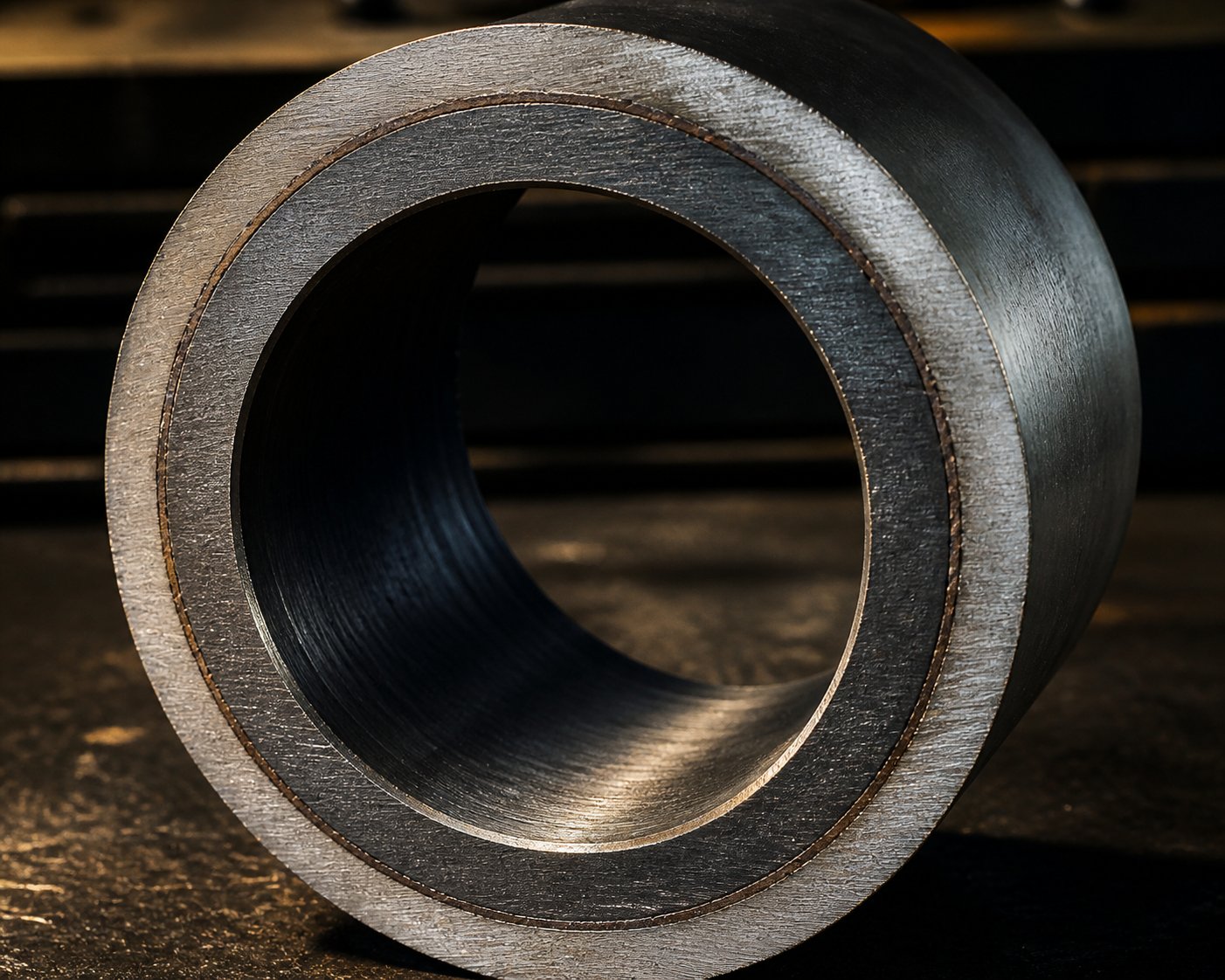
- Bimetallic barrel liners: A bimetallic barrel liner for injection molding consists of a wear-resistant alloy — commonly iron-boron or nickel-based compositions containing tungsten carbide particles — that is centrifugally cast inside the barrel bore. This process bonds a hard inner sleeve to the structural steel outer shell, achieving hardness levels up to 62 HRC. The result is dramatically improved resistance to both abrasive and corrosive wear. Bimetallic liners are the go-to choice for glass-fiber-filled engineering resins, mineral-filled compounds, and recycled plastics containing contaminants. Best fit: filled, reinforced, and recycled resins demanding high abrasion resistance.
- Chrome-plated bores: A thin but highly corrosion-resistant chromium layer — typically 10 to 50 micrometers thick — is applied to the barrel bore surface. Chrome plating excels at protecting against chemical attack from resins that release aggressive byproducts during processing, most notably PVC and certain fluoropolymers. While not as abrasion-resistant as bimetallic liners, the smooth, chemically inert surface prevents corrosive degradation that would otherwise eat through a standard nitrided barrel in months. Best fit: PVC, fluoropolymers, and other corrosive resin families.
Equally important is injection molding barrel bore tolerance and concentricity. The clearance between the screw flight outer diameter and the barrel bore must remain uniform around the full 360-degree circumference. If the bore is eccentric — even slightly off-center relative to the screw axis — one side of the screw rides closer to the barrel wall than the other. This creates uneven shear, accelerates localized wear, and produces inconsistent melt temperature across the flow channel. Precision barrel manufacturers hold bore concentricity within tight tolerances specifically because this single variable influences both melt quality and component service life simultaneously.
Feed Throat Design and Cooling
If you have ever troubleshot a machine that intermittently starves or surges, the feed throat is one of the first places to look. This short section — located where the hopper meets the barrel — rarely gets discussed in detail, yet it plays an outsized role in solids conveying performance.
The feed throat contains water-cooling channels that keep the barrel entrance cool enough to prevent pellets from softening prematurely. When pellets begin to melt too early, they stick to the barrel wall and to each other, forming a plug that blocks the flow of fresh material. This phenomenon, called bridging, starves the screw and causes erratic shot weights. Proper feed throat cooling maintains a sharp thermal boundary: cool enough on the feed side for solid pellets to be gripped and conveyed, warm enough just downstream for controlled melting to begin.
Beyond cooling, feed throat bore geometry matters. Most injection molding barrels use a smooth-bore feed section, where the throat interior is a plain, polished cylinder. Smooth bores rely entirely on the friction between the pellets and the barrel wall to push material forward. For many resins, this works well.
However, a grooved feed throat takes a different approach. Longitudinal or helical grooves machined into the feed section dramatically increase the frictional grip on solid pellets, forcing them forward with greater efficiency. As Davis-Standard's comparative studies demonstrate, groove feed designs achieve higher output rates with lower melt temperatures and reduced energy consumption compared to smooth-bore alternatives of comparable size. The grooved feed throat injection molding barrel design is especially effective for high-viscosity polyolefins like HDPE, where pellet slippage in a smooth bore limits throughput. The trade-off is that grooved feed sections generate higher back pressures and require more robust thrust bearing designs, so they are not a universal upgrade — but for the right application, the performance gains are substantial.
Barrel Heating Zones and Band Configuration
The barrel does not heat uniformly from end to end. Instead, it is divided into independently controlled heating zones — typically three to five, depending on barrel length and machine size — each wrapped with its own heater band and monitored by a dedicated thermocouple. This injection molding barrel heating zones configuration allows processors to create a deliberate temperature profile that complements the screw's mechanical work in each functional zone.
Two types of band heaters dominate the market:
- Mica band heaters: Constructed with resistive wire wound around a mica insulation core, these are the more economical choice. They heat up quickly and work well for standard applications, but they are limited in maximum watt density and tend to have shorter service lives in high-temperature environments.
- Ceramic band heaters: These use ceramic insulation that retains heat more effectively and supports higher watt densities. Ceramic bands deliver more uniform heating, reduce energy loss to the surrounding air, and generally last longer — making them the preferred option for engineering and high-performance resins that demand tight thermal control.
Regardless of heater type, contact with the barrel surface is critical. An air gap between the band and the barrel creates thermal lag — the controller reads one temperature while the barrel wall experiences another. As MD Plastics notes, even when every zone reads perfectly on the controller, the actual melt temperature is governed far more by shear, screw design, and backpressure than by heater bands alone. In many processes, 60 to 80 percent of the energy that melts the resin comes from mechanical shear generated by screw rotation, not from conductive heating through the barrel wall. The heater bands primarily maintain barrel temperature to prevent heat loss and support the screw's mechanical work — they do not do the heavy lifting by themselves.
Thermocouple placement deserves equal attention. A thermocouple that sits too shallow reads barrel skin temperature rather than the temperature at the bore surface. One that is improperly seated — loose in its well or corroded — gives readings that drift from reality, leading processors to chase phantom temperature problems. Best practice calls for thermocouples to be seated firmly at a consistent depth across all zones, positioned at roughly the midpoint of each zone's length for the most representative reading.
The interplay between zone count, zone placement, and screw geometry is where barrel thermal management becomes a true systems-engineering challenge. A barrel with five heating zones paired with a high-L/D screw gives processors far more granular control over the temperature profile than a three-zone barrel with a shorter screw. The heating zones must align logically with the screw's functional zones — zone 1 supporting solids conveying in the feed section, the middle zones spanning the compression region, and the front zones managing melt homogenization in the metering section. When this alignment is off, processors end up overheating one region to compensate for insufficient heat in another, wasting energy and narrowing the process window.
The materials inside the barrel — both the liner alloy resisting wear and the steel grades providing structural strength — tell only half the story of component longevity. The screw faces its own set of material science challenges, and the interplay between screw metallurgy and barrel liner chemistry determines how long the entire plasticizing system holds its tolerances under production conditions.
Screw and Barrel Material Science and Wear Resistance
A screw with perfect geometry and a barrel with flawless bore tolerances will still fail prematurely if they are made from the wrong materials. The resins running through the plasticizing unit impose relentless mechanical and chemical stress on every interior surface, and the steel grades, surface treatments, and coatings chosen for these components determine whether they last months or years. This is the dimension of injection molding barrel and screw performance that rarely gets discussed — yet it drives more unplanned downtime and replacement cost than almost any other factor.
Tool Steel Grades for Screws and Barrels
Not all steels are created equal, and the base material of your screw and barrel sets the ceiling for how long they can maintain their critical tolerances under production conditions. Here is where injection molding screw steel grades and hardness directly translate into real-world service life.
4140 alloy steel is the workhorse of general-purpose plasticizing components. It is readily available, easy to machine, and accepts surface treatments like nitriding well. With a typical working hardness of 28 to 32 HRC, it handles non-abrasive commodity resins adequately. However, it lacks the inherent wear resistance needed for filled or reinforced compounds, and once its surface treatment wears through, the softer base metal erodes quickly.
D2 tool steel steps up the performance ladder. Its high chromium and carbon content deliver hardness in the range of 58 to 62 HRC, providing moderate abrasion resistance that outlasts 4140 by a significant margin in mildly abrasive applications. D2 is a common choice for screws processing lightly filled engineering resins where the cost of CPM-series steels is not justified.
CPM-series particle metallurgy steels represent the top tier for highly abrasive service. Grades like CPM 9V — with 9.1% vanadium content and a fine, uniform dispersion of vanadium carbides — achieve hardness of 54 to 56 HRC while maintaining substantially higher toughness than conventional tool steels at comparable hardness. CPM 10V pushes vanadium content even higher for extreme abrasion resistance. These steels are purpose-built for processing glass-fiber-filled nylon, mineral-filled PBT, and other compounds that chew through lesser materials. The Crucible Particle Metallurgy process produces a much finer and more evenly distributed carbide structure than conventional melting, which is exactly why these grades resist abrasive wear so effectively — the hard carbide particles are uniformly embedded throughout the steel matrix rather than clustered in coarse bands.
The relationship between Rockwell C hardness and service life is not perfectly linear, but it is directional: higher hardness generally means slower wear, provided the steel retains enough toughness to resist chipping and fracture under the cyclic stresses of injection molding. A brittle screw flight that chips is worse than a softer one that wears gradually, so the balance between hardness and impact resistance matters as much as the peak hardness number.
Surface Treatments and Coatings
Even the best base steel benefits from surface engineering. Treatments and coatings add a protective armor layer that absorbs the brunt of wear and corrosion, extending the life of the underlying material considerably.
Nitriding — available in gas and ion (plasma) variants — diffuses nitrogen into the steel surface to create a hard case. As industry experts note, nitriding case-hardens the screw root and flight surfaces to a depth of approximately 0.015 to 0.020 inches, reaching hardness levels around 60 HRC. It is an economical first line of defense, particularly effective for non-abrasive and mildly abrasive resins. The limitation? That thin hardened layer eventually wears through, and when it does, the exposed base metal erodes rapidly — often with little warning unless the screw is pulled and inspected regularly.
Hard chrome plating provides a different kind of protection. Rather than hardening the steel surface, it deposits a thin chromium layer that excels at resisting chemical attack. Chrome plating is the standard defense for barrels and screws processing PVC, fluoropolymers, and other resins that release corrosive byproducts like hydrochloric acid during melting. It also creates an exceptionally smooth surface that reduces material adhesion and simplifies purging.
Tungsten carbide thermal spray coatings take wear protection to a higher level entirely. Applied via High Velocity Oxy-Fuel (HVOF) or similar spray-and-fuse processes, a tungsten carbide coating for injection molding screw applications encapsulates the flight surfaces and screw root in one of the hardest commercially available materials. This approach is particularly valuable for barrel and screw material selection for glass-filled resin processing, where abrasive fiber ends act like microscopic cutting tools grinding against every surface they contact.
Stellite alloy hardfacing — typically Stellite 6, with a hardness of approximately 38 to 42 HRC — is applied by weld overlay to screw flights and other high-wear areas. While not as hard as tungsten carbide, Stellite offers a unique combination of wear resistance, corrosion resistance, and machinability that makes it a practical intermediate solution. It is often used in combination with other treatments: for example, a screw might receive Stellite hardfacing on the flight lands and tungsten carbide encapsulation on the root, creating a layered defense tailored to the specific wear patterns of the application.
How Resin Type Drives Material Selection
Here is the critical insight that ties everything together: the resin you process determines the wear mechanism your screw and barrel face, and the wear mechanism dictates the material solution. Choosing materials without understanding your resin's specific attack mode is guesswork.
Three primary wear mechanisms dominate:
- Abrasive wear: Glass fibers, mineral fillers, and pigment particles act as cutting agents, physically grinding away screw flights and barrel bore surfaces. Glass-fiber-filled nylon and PBT are among the most aggressive offenders. The wear pattern typically concentrates in the feed section and early transition zone, where solid pellets with exposed filler particles scrub against unprotected steel surfaces before a melt film forms to provide lubrication.
- Corrosive wear: Resins like PVC, certain flame-retardant compounds, and fluoropolymers release acids or other chemically aggressive byproducts at processing temperatures. This chemical attack pits and erodes surfaces independently of mechanical contact, and it can destroy a standard nitrided barrel in remarkably short order.
- Adhesive wear: High-temperature engineering plastics like PEEK and PEI process at temperatures above 350 degrees Celsius, where metal-to-metal contact between screw flight tips and the barrel wall generates micro-welding and material transfer. This mechanism is less intuitive than abrasion or corrosion, but it causes progressive surface damage that degrades clearance control over time.
The table below maps these resin categories to the barrel liner and screw material combinations that best resist their specific wear mechanisms. Use it as a starting framework — actual selection should always account for filler loading percentages, processing temperatures, and production volume.
| Resin Category | Examples | Primary Wear Mechanism | Recommended Barrel Liner | Recommended Screw Material / Treatment |
|---|---|---|---|---|
| Commodity (unfilled) | PP, PE, PS, ABS | Minimal wear | Nitrided steel | 4140 steel, nitrided |
| Engineering (unfilled) | PC, POM, unfilled nylon | Mild abrasive / adhesive | Nitrided or bimetallic | D2 tool steel, nitrided |
| Abrasive (filled / reinforced) | Glass-filled nylon, glass-filled PBT, mineral-filled PP | Severe abrasive | Bimetallic (tungsten carbide particles) | CPM 9V or CPM 10V; tungsten carbide coated flights |
| Corrosive | PVC, PVDF, flame-retardant compounds | Chemical / corrosive | Chrome-plated or corrosion-resistant bimetallic | Corrosion-resistant alloy; hard chrome plated |
| High-performance | PEEK, PEI, PPS | Adhesive and high-temperature | Bimetallic (nickel-based alloy) | CPM-series steel; Stellite hardfaced flights |
Notice the pattern: nitrided vs bimetallic barrel liner wear resistance is not a universal competition with one clear winner. Nitrided liners are perfectly adequate — and far more cost-effective — for unfilled commodity resins that impose minimal mechanical or chemical stress. Bimetallic liners justify their higher cost only when the resin's filler content or chemical aggressiveness would burn through a nitrided surface in an unacceptably short time. The same logic applies to screw materials: a CPM 9V screw running unfilled polypropylene is over-specified and wasteful, while a nitrided 4140 screw processing 30% glass-filled nylon is under-specified and headed for premature failure.
The smartest approach is to match component metallurgy to the specific demands of your resin portfolio — and then pair that metallurgy with the right screw geometry. Because even the most wear-resistant screw will underperform if its compression ratio and flight design do not suit the polymer it is trying to plasticize.
Matching Injection Screw to Resin Type: A Practical Guide
A screw made from the finest tool steel with a premium tungsten carbide coating will still produce poor parts if its geometry does not match the polymer flowing through it. Every resin family melts differently, flows differently, and punishes design mismatches differently. Yet the practical question of which screw geometry fits which resin remains one of the least documented topics in injection molding. This section fills that gap with a clear, matching injection screw to resin type guide that connects polymer behavior to the specific screw parameters that manage it.
Amorphous vs. Semi-Crystalline Polymer Screw Requirements
The single biggest factor shaping screw geometry selection is whether the resin is amorphous or semi-crystalline. These two polymer families melt through fundamentally different mechanisms, and a screw optimized for one will often struggle with the other.
Amorphous resins — ABS, polycarbonate, polystyrene — have randomly oriented molecular chains with no crystalline structure to break down. As injection molding expert John Bozzelli describes it, amorphous resins melt like frozen butter: they gradually soften as heat builds, with no sharp transition point and no heat of fusion to overcome. A partially unmelted amorphous pellet behaves like taffy — it squashes harmlessly between the screw flight and barrel wall rather than gouging metal surfaces. This forgiving melt behavior means amorphous resins typically perform well with lower compression ratios, generally in the range of 2.0:1 to 2.5:1, which applies moderate shear without risking overheating.
Semi-crystalline resins — PE, PP, nylon, POM — tell a completely different story. Their ordered molecular chains stay hard until they reach a specific melting temperature, much like ice that does not soften at all until it hits 0 degrees Celsius. On top of reaching that temperature, the screw must deliver enough additional energy to overcome the heat of fusion and break apart the crystalline structure. A kilogram of nylon 6, for example, requires roughly twice the energy to melt compared to a kilogram of ABS — about 716 BTU/kg versus 342 — despite similar processing temperatures.
This sharp melt transition and higher energy demand make the best screw compression ratio for semi-crystalline polymers significantly more aggressive: typically 2.5:1 to 3.5:1, with a more active transition zone that applies greater shear heat and pressure. The challenge is that semi-crystalline pellets resist melting until they suddenly give way, creating a phenomenon called solid-bed breakup. Some pellets receive enough energy to melt completely while others pass through the transition zone only partially melted. These unmelted fragments can end up in the molded part and accelerate screw wear — even in a resin as seemingly gentle as polyethylene.
The practical takeaway? Running a semi-crystalline resin on a low-compression screw designed for amorphous materials almost guarantees poor melt homogeneity. Conversely, running an amorphous resin through a high-compression screw designed for semi-crystalline polymers generates excessive shear heat that risks degradation and discoloration.
Specialty Screws for Challenging Materials
Some resins push screw design requirements far beyond the amorphous-versus-semi-crystalline baseline. Three material categories stand out for demanding geometry that differs substantially from general-purpose designs.
PVC screws require the most cautious approach of any common polymer. PVC is thermally sensitive and releases hydrochloric acid when overheated, so every aspect of PVC injection molding screw geometry requirements centers on minimizing shear and preventing localized hot spots. According to Viplas, PVC screws use a low compression ratio — typically between 1.5:1 and 2.5:1 for rigid PVC — with screw profiles specifically optimized to avoid excessive shearing that triggers thermal degradation. Degassing zones may be incorporated to evacuate HCl vapors, and the entire screw must be constructed from corrosion-resistant materials or coated with hard chrome to survive the chemical environment. Temperature control precision is equally critical: PVC has one of the narrowest processing windows of any commodity resin, and even small thermal overshoots can trigger rapid decomposition.
Glass-filled resin screws face the opposite problem: not thermal sensitivity, but relentless abrasion. Glass fibers act like microscopic cutting tools, grinding away flight surfaces and barrel bore walls with every rotation. Screws for these compounds need wear-resistant flight materials — think CPM-series steels or tungsten carbide coatings as discussed in the previous section — combined with geometry that minimizes unnecessary turbulence while still achieving thorough melting. Some processors opt for barrier screw designs that separate the solid and melt pools, reducing the exposure of abrasive unmelted pellets to flight surfaces. Flight widths may also be increased slightly to provide more wear margin, even though this reduces channel volume.
High-temperature engineering plastics like PEEK, PEI, and PPS process at temperatures exceeding 350 degrees Celsius and demand extended residence time for the resin to fully plasticize. Longer L/D ratios — 24:1 or higher — give the screw more working length to deliver the enormous amount of energy these resins require. Shorter screws simply cannot generate enough shear heat and barrel conduction over their limited length to achieve a uniform melt at these extreme temperatures. These applications also benefit from deeper metering zones that allow the melt to stabilize thermally before injection.
Barrier Screws and Mixing Elements
General-purpose screws work well for a wide range of applications, but they have an inherent limitation: the solid pellets and the molten resin share the same channel throughout the transition zone. This co-mingling creates opportunities for solid-bed breakup, where chunks of unmelted material break free and drift into regions that should contain only homogeneous melt.
A barrier screw design for injection molding addresses this problem by introducing a secondary flight — the barrier flight — that physically separates the solid bed from the melt pool. As melting progresses, the molten resin flows over the barrier flight into a dedicated melt channel, while the remaining solids stay confined in their own channel under continued compression. This separation prevents unmelted fragments from bypassing the melting zone and contaminating the metered melt. Common barrier screw designs include the Maddock barrier (which uses a straight barrier section near the screw tip) and the spiral barrier (which introduces the barrier flight progressively along the transition zone for a more gradual separation).
Barrier designs are not without trade-offs. As Bozzelli cautions, some barrier screws can cause degradation and excessive black specks if the resin is held too long in the narrow channels. For semi-crystalline resins at large shot sizes, he recommends specifying a screw designed specifically for melt uniformity — with a minimum L/D of 20:1 and preferably 24:1 — rather than defaulting to a barrier design that may introduce its own set of problems.
Beyond barrier flights, mixing elements for injection molding screw designs offer another tool for improving melt quality. These are specialized sections — typically added near the screw tip, just upstream of the check valve — that force the melt through channels designed to enhance dispersive or distributive mixing:
- Maddock (Union Carbide) mixers: A series of alternating inlet and outlet flutes that shear the melt through narrow slots, breaking up any remaining unmelt fragments and thermal inconsistencies. This is a dispersive mixing element — it applies high shear to break things apart.
- Pineapple mixers: A section covered in a diamond-pattern array of pins or faceted cuts that repeatedly split and recombine the melt stream. This is primarily a distributive element — it reorients the melt to improve additive dispersion and color uniformity without excessive shear.
- Dulmage mixing sections: Multiple sets of interrupted flights that force the melt to flow through a series of shearing and recombination steps. These provide a blend of dispersive and distributive mixing and are commonly used when color concentrate distribution is a priority.
The choice between barrier flights, mixing elements, or both depends on the specific defect you are trying to eliminate. Unmelted pellets point toward a barrier design or a more aggressive transition zone. Color streaks and additive dispersion failures call for a mixing section. In many cases, a combination — a barrier screw with a distributive mixing element near the tip — provides the most robust melt quality across a range of operating conditions.
The table below consolidates the key screw parameters for common resin families into a single reference. Use it as your starting framework when specifying new plasticizing components or evaluating whether your current screw geometry suits your material portfolio.
| Resin Family | Compression Ratio | Recommended L/D | Flight Depth Guidance | Barrier Flights? | Mixing Elements? |
|---|---|---|---|---|---|
| PP, PE (unfilled semi-crystalline) | 2.5:1 – 3.5:1 | 20:1 – 24:1 | Deep feed zone; moderately shallow metering zone | Recommended for large shots | Distributive mixer for color applications |
| PS, ABS (amorphous) | 2.0:1 – 2.5:1 | 20:1 – 22:1 | Moderate feed depth; gradual transition | Optional | Optional for additive blending |
| PC, PMMA (amorphous engineering) | 2.0:1 – 2.5:1 | 22:1 – 24:1 | Moderate feed depth; extended metering zone for thermal uniformity | Optional | Recommended for optical clarity grades |
| Nylon, POM (semi-crystalline engineering) | 2.5:1 – 3.5:1 | 22:1 – 24:1 | Deep feed zone; aggressive transition taper | Recommended | Dispersive mixer to eliminate unmelt |
| Glass-filled nylon, PBT | 2.5:1 – 3.0:1 | 22:1 – 24:1 | Moderate depth; wider flights for wear resistance | Recommended (reduces fiber-on-metal contact) | Maddock mixer for fiber distribution |
| PVC (rigid) | 1.5:1 – 2.5:1 | 18:1 – 22:1 | Shallow throughout; minimal shear generation | Sometimes (with caution for dead spots) | Low-shear distributive elements only |
| PEEK, PEI, PPS | 2.5:1 – 3.0:1 | 24:1+ | Deep feed zone; extended metering zone | Recommended | Dispersive + distributive combination |
Keep in mind that this table represents general starting points. Actual screw specifications should account for your specific shot size relative to barrel capacity, cycle time targets, filler loading percentages, and surface finish requirements. For processors who run multiple resin families on the same machine, the reality is that no single screw geometry optimizes every material — which is why having access to screws engineered for your exact application matters. Manufacturers like NANHAIYA offer custom screw barrel manufacturing matched to specific resin families, serving injection molding factories and machine rebuilders who need plasticizing components designed for their particular material portfolio rather than a one-size-fits-all compromise.
Getting the geometry right solves half the plasticization puzzle. The other half — managing the thermal energy that surrounds and interacts with that geometry — depends on how precisely you control barrel temperatures and how well your heating system complements the shear energy the screw generates.
Barrel Temperature Control and Heating Systems
Here is a fact that surprises many processors: the heater bands wrapped around your barrel are not doing most of the melting. In many injection molding processes, 60 to 80 percent of the thermal energy that actually converts solid pellets into a homogeneous melt comes from mechanical shear — friction generated by the screw rotating against the resin and barrel wall. The barrel heaters primarily maintain wall temperature, prevent radiant heat loss, and supplement the screw's mechanical work. Misunderstand this relationship between shear heat vs barrel heater energy in injection molding, and you will spend months chasing temperature setpoints that never fix the real problem.
That does not mean heater bands are unimportant. Far from it. They establish the thermal baseline that allows the screw to do its job efficiently, and they provide the fine-tuned zone control that separates a stable process from one plagued by viscosity swings and defects. The key is understanding what the heating system can and cannot do — and designing your temperature strategy around that reality.
How Barrel Heater Bands Work
Every injection molding barrel relies on band heaters clamped directly to its outer surface to deliver conductive heat through the steel wall and into the resin. Two technologies dominate the market, and choosing between ceramic vs mica band heaters for your injection molding barrel comes down to operating temperature, energy efficiency, and physical space constraints.
Mica band heaters use nickel-chromium resistance wire wound around a natural mica insulation core, enclosed in a thin stainless steel sheath. They heat up fast, have an ultra-thin profile of roughly 3 to 5 mm, and cost less upfront. The trade-off? Mica bands rely almost exclusively on direct conduction — heat must pass from the wire through the mica, through the steel sheath, and into the barrel. As Hongtai's engineering data shows, even a 0.5 mm air gap from loose clamping disrupts this conduction path and creates localized hot spots that melt the internal resistance wire. Their maximum operating temperature is approximately 340 degrees Celsius, and watt density tops out around 3 W/cm squared. For standard commodity resins like PP, PE, and ABS — where barrel temperatures stay safely below 300 degrees Celsius — mica bands are a practical, economical choice.
Ceramic band heaters take a fundamentally different approach. Internal helical resistance coils are threaded through interlocking steatite ceramic tiles, which absorb heat and re-emit it as far-infrared radiation. This dual transfer mechanism — conduction plus radiation — means ceramic bands do not require the flawless surface contact that mica elements demand. They tolerate operating temperatures up to 600 degrees Celsius and support watt densities up to 6 W/cm squared. A built-in 12 mm ceramic fiber insulation blanket between the heating elements and the outer metal sheath forces thermal energy inward toward the barrel, reducing power consumption by 25 to 30 percent compared to uninsulated mica bands. For high-temperature engineering resins like PEEK and nylon — or any 24/7 production line where energy efficiency matters — ceramic bands are the required specification.
Regardless of which type you select, watt density — the amount of heating power per unit of heater surface area — must match the process demand. Specifying too low a watt density forces heater bands to run at full power continuously, shortening their lifespan. Specifying too high a watt density can overshoot barrel temperature during low-demand phases and create thermal cycling that destabilizes the melt. And in both cases, the heater band must sit flush against the barrel with zero air gaps. A loose band is a failing band, regardless of its material or watt density rating.
Temperature Zone Strategy and Thermocouple Placement
Setting every barrel zone to the same temperature and hoping for the best is not a strategy — it is a gamble. Injection molding barrel temperature profile strategies must be deliberately chosen based on the resin being processed, the screw geometry in use, and the part quality requirements. Four common profiles form the foundation of thermal management in the plasticizing unit:
- Standard ramp (ascending) profile: Temperature increases progressively from the feed zone to the nozzle. This is the most widely used profile for commodity and general-purpose resins like PP, PS, ABS, and HDPE. It matches the screw's natural melting progression — pellets soften gradually in zone 1, collapse and melt through the compression section, and reach full homogeneity in the metering zone. The gradual increase prevents premature melting in the feed zone while ensuring complete plasticization before the nozzle.
- Flat profile: All barrel zones run at or near the same temperature. This approach suits shear-sensitive resins like polycarbonate, PMMA, and certain TPUs, which develop most of their melt energy from mechanical shear rather than conducted barrel heat. A uniform thermal environment reduces the risk of localized degradation. The caveat? Flat profiles amplify any upstream issues in screw-generated shear — if the screw design is weak or backpressure is too low, you will get unmelt and poor mixing.
- Hump profile: The middle barrel zones run hotter than both the feed and nozzle zones, creating a temperature peak in the compression region. This strategy concentrates thermal energy where the most intense melting occurs and can help resins that benefit from aggressive energy input during the compression phase while maintaining lower temperatures at the extremes for feed stability and drool prevention.
- Reverse profile: Zone 1 runs hottest, with temperatures gradually decreasing toward the nozzle. This counterintuitive approach works for high-viscosity resins and slippery pellets — like certain nylons — where feed-zone slippage is a persistent problem. Higher heat at the feed section softens pellet surfaces just enough to improve frictional grip, while cooler downstream zones control final melt viscosity. Reverse profiles are rarely used unless the material specifically demands it, because overheating zone 1 can cause bridging and screw starvation.
Choosing the right profile is only half the equation. Thermocouple placement determines whether you are actually reading what you think you are reading. A thermocouple that sits too shallow in its well measures barrel skin temperature — which can differ significantly from the temperature at the bore surface where the resin contacts the steel. One that is loose, corroded, or improperly seated reads ambient air rather than barrel temperature, sending false data to the PID controller and triggering phantom heating or cooling responses. A University of Kassel study on machine-specific behavior found that temperature fluctuations driven by controller dynamics can have a noticeable impact on melt flow characteristics and part quality, including polymer degradation in thermally sensitive materials. Best practice calls for thermocouples seated firmly at a consistent depth in each zone, positioned at the midpoint of the zone's length for the most representative reading. When in doubt, verify displayed zone temperatures against an independent melt probe at the nozzle — the barrel display shows what the steel is doing, not what the polymer is experiencing.
Feed Throat Cooling and Its Impact on Throughput
Imagine pellets entering the barrel only to melt before the screw can grip them. They stick to the barrel wall, stick to each other, and form a plug that blocks fresh material from feeding. This is bridging — and it almost always traces back to inadequate feed throat cooling.
The feed throat sits at the junction between the hopper and the first heated barrel zone. Its water-cooling channels create a deliberate thermal boundary: cool enough on the hopper side to keep pellets solid and free-flowing, warm enough just downstream where zone 1 heating begins. This boundary is surprisingly narrow and sensitive. If the cooling water flow rate drops, if the water temperature rises due to a shared cooling loop running too warm, or if scale buildup insulates the cooling channels from the barrel wall, the thermal boundary shifts downstream — and pellets begin softening too early.
Feed throat cooling injection molding troubleshooting often reveals that the root cause of intermittent starved feeding and erratic shot weights is not a screw or barrel problem at all — it is a thermal management failure at the very entrance of the system. Feed throat temperature setpoints interact directly with barrel zone 1 temperature: if zone 1 runs hot while the feed throat cooling is marginal, heat migrates backward into the throat area and softens pellets before the screw can convey them. Processors sometimes lower zone 1 temperature to compensate, but this just shifts the problem downstream into the compression zone, where insufficient heat input leads to unmelt and pressure spikes.
The correct approach is to treat feed throat cooling as its own independent control loop. Monitor water temperature in and out of the feed throat, maintain adequate flow, and verify that the throat remains clear of scale or debris. For polyolefins processed through grooved feed sections — where aggressive solids conveying generates significant frictional heat — feed throat cooling capacity may need to exceed what a standard smooth-bore system requires.
Thermal management across the entire barrel length — from the cooled feed throat through multiple independently controlled heating zones to the nozzle — creates the thermal environment within which the screw does its work. When that environment is stable and correctly profiled, defects decline and process windows widen. When it drifts — through failing heater bands, inaccurate thermocouples, or overlooked feed throat cooling — the symptoms show up in the molded parts. And tracing those part defects back to their specific screw-and-barrel root causes is where most processors need the most practical guidance.
Troubleshooting Molding Defects Traced to Screw and Barrel Issues
You have adjusted temperatures, tweaked injection speeds, raised and lowered back pressure — and the defect persists. Sound familiar? Many processors exhaust every parameter on the control screen before considering that the problem lives inside the plasticizing unit itself. A worn screw flight, a mismatched compression ratio, or a corroded barrel liner can produce defects that no amount of process adjustment will fix. The root cause is mechanical, not parametric, and the solution requires looking past the HMI and into the barrel.
What follows is a practical guide that maps specific part defects back to their screw-and-barrel origins, giving you a diagnostic shortcut that most troubleshooting resources skip entirely.
Defects Caused by Screw Wear
Screw wear is gradual. The flight outer diameter loses fractions of a millimeter over thousands of hours, and the barrel bore slowly enlarges to match. You will not notice it happening — but you will notice the consequences in your parts long before anyone pulls the screw for measurement.
When the clearance between screw flights and the barrel wall exceeds its designed tolerance, several things go wrong simultaneously:
- Inconsistent shot size: Enlarged clearance lets melt leak backward over the flights during injection. Combined with a worn check ring that no longer seals properly, this backflow means the machine delivers a different amount of material on every cycle. Shot size variation from a worn check ring and barrel clearance is one of the most common — and most misdiagnosed — quality problems in aging machines. Operators often compensate by adjusting transfer position or packing pressure, masking the real issue while the wear continues to progress.
- Unmelted pellets: A worn screw loses conveying efficiency because material slips backward through the widened gap instead of being driven forward under compression. The resin spends less effective time in the compression and metering zones, and pellets that would normally be fully plasticized pass through only partially melted. If you are finding unmelted pellets caused by screw wear in injection molding parts, increasing barrel temperature is a temporary patch — the real fix is restoring proper flight-to-bore clearance.
- Poor color mixing: Worn flights reduce the shear and mixing intensity the screw applies to the melt. Color concentrate or masterbatch that would normally be dispersed thoroughly instead travels through the barrel in streaks. The melt lacks the mechanical energy to homogenize pigment particles, producing visible color variation in finished parts.
- Extended cycle times: As conveying efficiency drops, recovery time — the period during which the screw rotates to build the next shot — increases. Early warning signs include fluctuating melt pressure readings and sudden drops in production speed. The machine works harder to move the same amount of material, consuming more energy per part while producing fewer parts per hour.
Defects Linked to Screw Geometry Mismatch
Wear is not the only culprit. Sometimes the screw is brand new and dimensionally perfect — but its geometry simply does not suit the resin being processed. These mismatches produce a different category of defects that temperature adjustments cannot resolve.
Excessive compression ratio is one of the most destructive mismatches. When a high-compression screw designed for semi-crystalline polyolefins is used with a heat-sensitive material like PVC or certain flame-retardant grades, the aggressive shear generates more frictional heat than the resin can tolerate. The result? Injection molding burn marks from screw compression ratio mismatch — dark streaks, charred spots, or degradation marks that appear consistently regardless of how far you lower barrel temperatures. The resin is not overheating because of the heaters; it is overheating because the screw is mechanically cooking it. Switching to a screw with a lower compression ratio and a more gradual transition zone is the only lasting solution.
Insufficient compression creates the opposite problem. A low-compression screw running a semi-crystalline resin that needs aggressive energy input will fail to fully melt and homogenize the polymer. The symptoms show up as splay — silver streaks on the part surface caused by moisture or volatiles trapped in a poorly plasticized melt — and as unmelted gels that create surface blemishes or weak spots in the finished part.
Geometry mismatches also extend to L/D ratio and mixing capability. A short-L/D screw without any mixing elements running a color-critical application will produce color streaks and additive dispersion failures that no amount of increased back pressure fully eliminates. The melt simply does not spend enough time under enough mixing intensity to achieve the homogeneity the part requires. Adding a Maddock or Dulmage mixing section — or specifying a longer L/D screw — addresses the root cause rather than forcing a compromised process to compensate.
Barrel-Related Defects and Their Signatures
The barrel contributes its own set of defect signatures, and they are often the hardest to diagnose because the evidence hides inside a component you cannot easily see during production.
Black specks are the telltale signature of degraded material trapped inside the barrel. When the barrel liner develops pitting, gouges, or dead spots — areas where small pockets of resin stagnate rather than flowing forward — material accumulates in those voids, cooks at processing temperature for extended periods, and eventually breaks free as carbonized particles that contaminate the melt stream. The black specks injection molding barrel screw cause is almost always a combination of surface damage and prolonged residence time. Carbon buildup from degraded plastic and leftover material from previous runs compounds the problem, especially during material changeovers where purging procedures are inadequate. Corroded barrel bores from processing chemically aggressive resins like PVC or flame-retardant compounds create even more surface irregularities that trap material.
Failed heater bands create cold spots along the barrel where the steel temperature drops below the resin's melt point. The polymer passing through that zone does not fully plasticize, producing unmelted gels — small, hard inclusions embedded in an otherwise fluid melt. These gels show up as surface defects, gate blush, or cold slugs at the flow front. A single burned-out heater band can create a cold zone several inches long, and because the adjacent zones try to compensate by running hotter, the result is an uneven thermal profile that degrades overall melt quality even beyond the immediate cold spot.
Corroded barrel bores from extended processing of corrosive resins contaminate parts in a more insidious way. Pitting and surface roughening increase the drag on the melt, alter flow dynamics, and release metallic contamination particles into the resin stream. Parts may show discoloration, surface imperfections, or even degraded mechanical properties from metal-catalyzed polymer breakdown. If the barrel liner was not specified for corrosion resistance — a chrome-plated or corrosion-resistant bimetallic liner — the damage accumulates progressively and cannot be reversed without relining or replacing the barrel.
The table below consolidates these defect-cause-action relationships into a single diagnostic reference. When a persistent defect resists process parameter adjustments, use this as your checklist to evaluate whether the plasticizing unit itself is the source.
| Defect | Likely Screw / Barrel Root Cause | Recommended Corrective Action |
|---|---|---|
| Burn marks / degradation streaks | Excessive screw compression ratio for the resin; dead spots in damaged barrel liner trapping and overheating material | Specify a screw with a lower compression ratio and more gradual transition; inspect barrel bore for pitting and reline or replace if damaged |
| Splay (silver streaks) | Insufficient compression ratio failing to plasticize resin fully; inadequate shear leaving moisture and volatiles trapped in melt | Switch to a screw with a higher compression ratio suited to the resin family; verify material drying and consider adding a mixing section |
| Unmelted pellets | Worn screw flights reducing conveying efficiency and residence time; check valve leaking melt backward; insufficient compression for semi-crystalline resin | Measure screw flight OD and barrel bore ID to quantify wear; replace worn components; match screw geometry to resin melt behavior |
| Black specks | Barrel liner damage creating dead spots that trap and degrade resin; carbon buildup from inadequate purging; corroded barrel bore | Pull screw and inspect barrel bore for pitting, gouges, or corrosion; improve purging procedures; upgrade to corrosion-resistant liner if processing aggressive resins |
| Color streaks | Worn screw flights reducing mixing intensity; incorrect L/D ratio or absence of mixing elements; poor check-valve seal causing melt recirculation | Add dispersive or distributive mixing section; specify longer L/D screw; inspect and replace worn check ring |
| Shot-size variation | Worn check ring failing to seal during injection; enlarged barrel bore clearance allowing melt backflow over flights | Inspect check ring for wear and scoring; measure barrel bore and screw flight OD; replace both if clearance exceeds tolerance |
Notice a pattern in the corrective actions: nearly every entry ends with a physical inspection of the screw, check ring, or barrel bore. That is not coincidental. Many injection molding defects stem from mechanical wear rather than processing parameters, and the only way to confirm or rule out the plasticizing unit as a root cause is to measure what is actually happening inside it. Process engineers who treat barrel and screw inspection as a troubleshooting step — not just a scheduled maintenance task — catch problems faster and avoid the costly cycle of parameter chasing that never reaches the real issue.
Knowing which defects trace back to the plasticizing unit is the diagnostic half of the equation. The operational half — preventing those defects through systematic wear monitoring, proper purging, and timely component replacement — is what separates reactive firefighting from a proactive maintenance strategy that keeps the plasticizing system performing within tolerance, year after year.
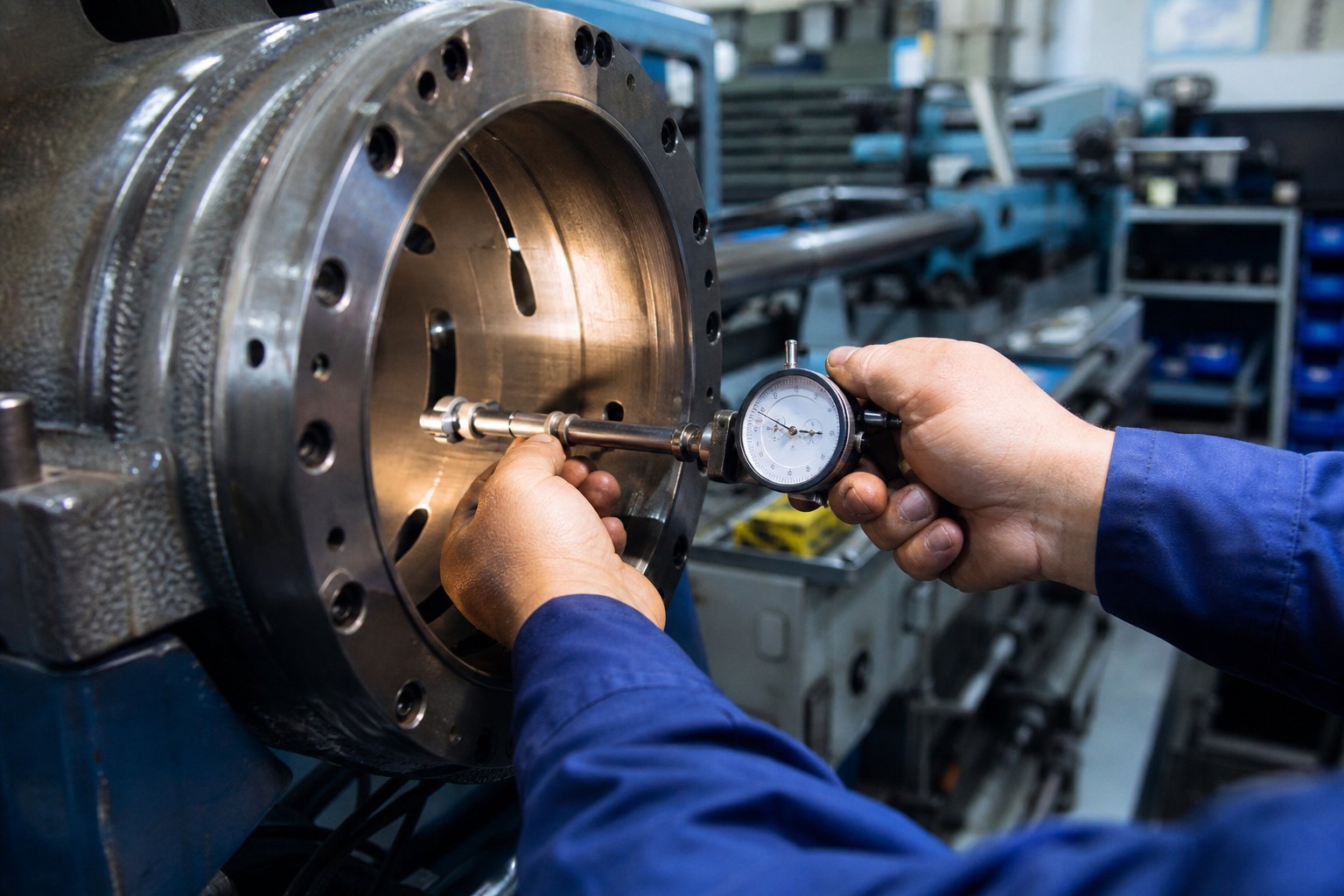
Maintenance and Wear Monitoring Best Practices for Injection Molding Screws and Barrels
Catching a defect on a molded part tells you something already went wrong. Catching a wear trend inside the plasticizing unit tells you something is about to go wrong — early enough to plan a repair during scheduled downtime instead of scrambling through an emergency shutdown. That difference is the core of a preventive maintenance schedule for the injection molding plasticizing unit: a structured, repeatable program that monitors screw and barrel condition over time, uses proper purging procedures to protect components between runs, and relies on objective measurements — not guesswork — to drive replacement decisions.
A structured PM program does more than prevent breakdowns. As Reiloy USA's Preventive Maintenance Handbook emphasizes, tracking component wear life also explains process variations over time. As screws and barrels wear, changes appear in cycle times, scrap rates, energy consumption, and unplanned downtime — all of which erode profitability gradually enough to go unnoticed until someone finally pulls the screw and sees the damage firsthand.
Preventive Maintenance Schedules and Purging Best Practices
The most common way processors destroy a perfectly good screw has nothing to do with running it too many hours. It happens on a Monday morning: someone starts the machine cold and hits the screw rotation button before the barrel has reached operating temperature. The solidified resin plug from the previous shutdown locks the screw in place, and the torque from the drive motor twists or snaps the screw shank. Cold-start screw breakage is entirely preventable — and entirely the operator's responsibility.
Proper startup begins with bringing all barrel zones to their operating setpoints and soaking for a minimum of 15 to 20 minutes before engaging screw rotation. This soak period allows conducted heat to soften the resin plug surrounding the screw, freeing the flights from the solidified mass. Skipping the soak — or reducing it to save a few minutes — risks catastrophic damage to a component that costs thousands of dollars to replace.
Proper shutdown is equally critical. Before turning off the heaters, purge the barrel thoroughly to remove the production resin — especially if it is corrosive (PVC, flame-retardant compounds) or thermally unstable. Reiloy USA recommends always removing corrosive and filled resins before idling equipment, because residual material left in a cooling barrel can pit screw surfaces and attack barrel liners as acids concentrate during solidification.
This is where purging procedures for injection molding barrel screw maintenance become a strategic tool rather than a housekeeping chore. Commercial purging compounds (CPCs) are formulated to outperform virgin resin or regrind for system cleaning in several key ways:
- CPCs remove carbon deposits, residual color, fillers, and degraded material more effectively than production resin alone, preventing the buildup that creates black specks and dead spots over time.
- Thermally stable CPCs can seal the barrel during shutdown periods, preventing oxidation that would otherwise generate contamination on the next startup.
- Some CPCs are designed to cool and shrink, pulling built-up material and carbon away from metal surfaces — a routine use that reduces the frequency of manual screw pulls for deep cleaning.
- Specialized CPCs expand into negative-flow areas like check-valve pockets and flight roots, removing residual material that regrind or virgin resin cannot reach.
A technically competent CPC supplier can match the proper purging grade to your specific resin, temperature range, and process type. The cost of a quality CPC is almost always lower than the combined cost of extended changeover times, scrap from contamination, and accelerated wear from residue buildup.
Inspection intervals should be driven by the material being processed, not by a fixed calendar date. When running primarily reinforced or filled resins, establish a six-month inspection cycle until wear trends are documented. For unfilled resins, annual inspections are a reasonable starting point. Once you know how long a screw, barrel, and check valve last in a given process, you can schedule replacements proactively — eliminating the downtime surprises that reactive maintenance inevitably delivers.
Wear Measurement and Replacement Criteria
Opinions about when to replace a screw or barrel are meaningless without measurements. Injection molding screw and barrel wear measurement requires two specific tools and a disciplined documentation process.
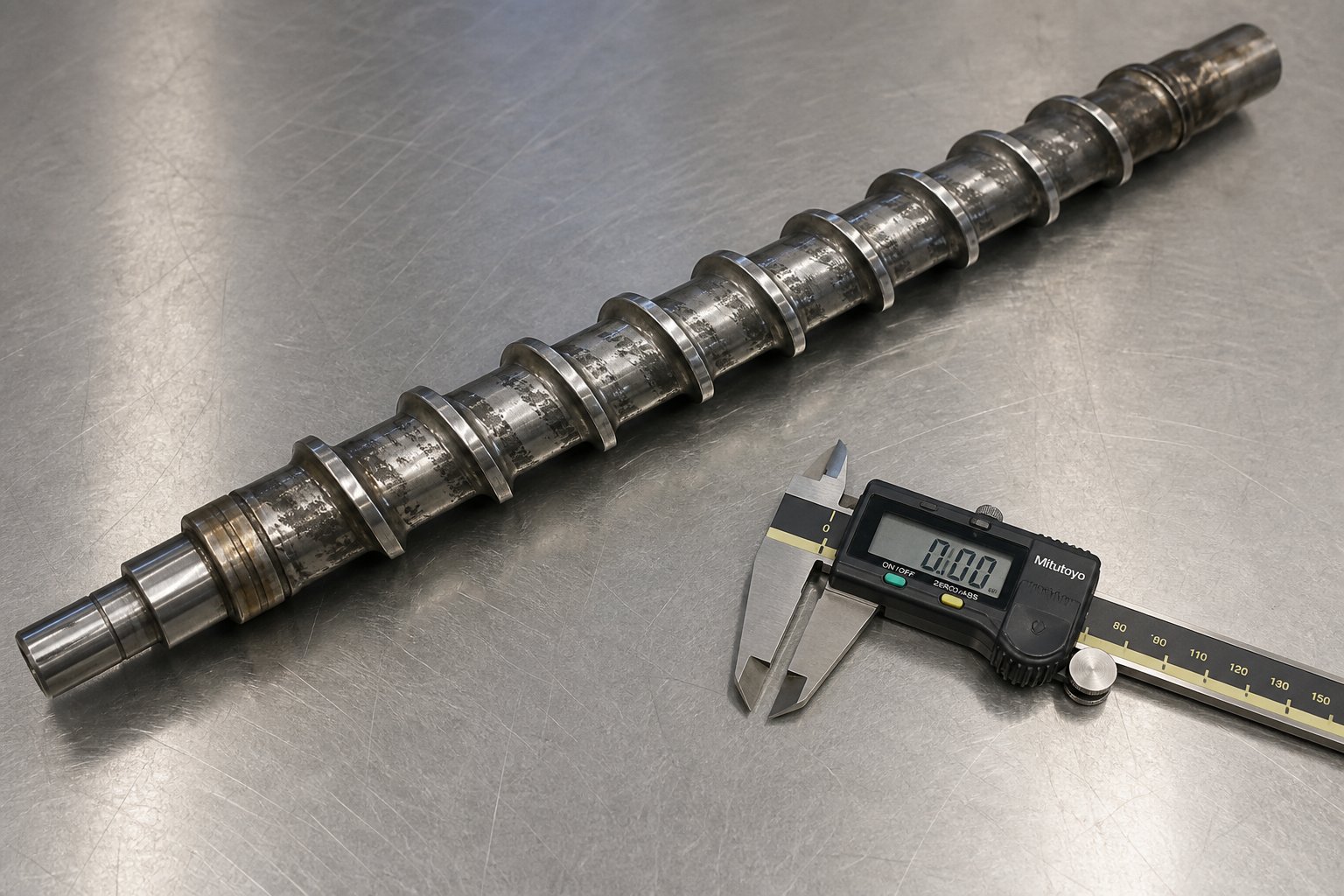
For the screw, you need an OD bar micrometer — a standard micrometer modified with an extended anvil bar that spans across the screw flights to measure the outer diameter of the flight lands accurately. Davis-Standard's maintenance guide walks through the procedure: first, thoroughly clean all solidified residue from the screw surface using brass tools and copper gauze — never steel wire brushes or aggressive abrasives that would damage the surface and distort readings. Then measure the flight OD at multiple points along the screw length, recording each reading with its distance from the screw tip. A tape measure serves as your position reference.
For the barrel, a bore gauge (internal micrometer) measures the inside diameter at multiple positions and orientations along the barrel length. Comparing bore ID readings against the original specification reveals how much material the barrel wall has lost, and measuring at multiple clock positions around each cross-section exposes any ovality — uneven wear that indicates alignment problems or eccentric screw loading.
The critical metric is diametrical clearance — the total gap between the screw flight OD and the barrel bore ID. Industry guidelines from maintenance engineering references break this into actionable thresholds:
| Total Diametrical Clearance | Status | Action Required |
|---|---|---|
| Less than 0.1 mm | Factory specification | No action — full performance. Log baseline measurements for future comparison. |
| 0.1 to 0.2 mm | Watch zone | Still productive for general parts. Increase inspection frequency. Trend cycle time and shot weight weekly. |
| 0.2 to 0.3 mm | Action zone | Recovery time climbing and shot weight drifting. Plan rebuild or replacement during the next scheduled shutdown. |
| Greater than 0.3 mm | Excessive | Melt leakage actively compromising quality. Rebuild or replace immediately — scrap cost exceeds repair cost. |
A general rule of thumb for new components: clearance starts at approximately 0.001 inch per inch of screw diameter, per side. A 3.5-inch screw, for example, begins life with about 0.0035 inches of clearance per side, or 0.007 inches total diametrical clearance.
The question of when to replace injection molding screw and barrel versus rebuilding depends on several factors beyond raw clearance numbers. Rebuilds — which typically involve re-chroming or re-hardfacing worn screw flights and honing the barrel bore — cost roughly 40 to 60 percent of new component pricing and restore 90 to 95 percent of original performance when the base steel remains structurally sound. Full replacement makes more sense when the base metal is compromised (cracked, deeply pitted, or corroded through the hardened layer), when you are upgrading to a more wear-resistant metallurgy to better match your resin portfolio, or when the rebuild turnaround time would cause more production loss than the cost premium of a new assembly.
One critical decision: if the screw has worn into the action zone, measure the barrel bore before deciding. Replacing only the screw and reinstalling it into a worn barrel accelerates wear on the new screw and wastes the investment — a lesson reinforced throughout this article's systems-level perspective. When both components show significant wear, replacing them as a matched pair restores original clearances and delivers the full expected service life from both parts.
Storage and Handling of Spare Components
Having a spare screw on the shelf can turn a multi-day emergency into a same-shift swap — but only if that spare is ready to install when you need it. Improperly stored screws develop surface corrosion, especially on precision-ground flight surfaces and polished root areas where even light oxidation degrades clearance control and increases break-in wear.
Apply a rust-preventive oil or vapor-corrosion-inhibitor (VCI) coating to all exposed steel surfaces before storing spare screws. Store them horizontally on padded V-blocks or cradles that support the shaft at multiple points — hanging a screw vertically by one end or leaning it against a wall invites bending from its own weight over time. Keep storage areas dry and temperature-stable; a climate-controlled maintenance crib is ideal, but at minimum, wrap coated screws in VCI paper or bags to protect against humidity.
Equally important — and frequently neglected — is documentation. Every spare screw should have a tag or record listing its diameter, L/D ratio, compression ratio, flight depths by zone, check-valve style, base material, surface treatment, and the OEM or supplier part number. When the time comes to reorder, having complete specifications on file eliminates guesswork and ensures the replacement matches the application. Processors who run multiple machines with different screw designs will appreciate this discipline the first time a Friday afternoon emergency requires pulling the right spare from inventory without delay.
The following ordered list consolidates the complete preventive maintenance schedule into a single chronological reference — from the checks you should perform every shift through the comprehensive annual overhaul that resets your baseline:
- Every shift (daily): Visually inspect heater bands for damage or discoloration. Verify thermocouple readings across all zones. Check the feed throat area for pellet bridging or unusual sounds during screw rotation. Log cycle time, recovery time, and cushion position to establish trend baselines.
- Weekly: Torque-check heater band clamps to maintain full barrel contact. Clean the feed throat and inspect hopper magnets for tramp metal. Verify feed throat cooling water flow and temperature. Review the week's cycle time and shot weight trend data for drift.
- Monthly: Test heater band resistance with a multimeter to identify elements nearing failure. Perform a thermocouple calibration check. Inspect the check ring and non-return valve for wear during any scheduled screw pull. Run a commercial purging compound through the system to remove carbon buildup and residue accumulation.
- Quarterly (or every 1,000-1,500 operating hours): Deep-clean the barrel with an appropriate CPC before pulling the screw for visual inspection. Examine screw flight surfaces for scoring, galling, or coating loss. Inspect the check ring seat and sliding surfaces for wear and carbon deposits. Replace nozzle tips if processing abrasive resins.
- Semi-annually (for filled or reinforced resins): Perform full dimensional measurement — screw flight OD at multiple points along the length, barrel bore ID at multiple positions and orientations. Compare against baseline measurements to quantify wear rate. Inspect and rebuild or replace the check valve assembly if sealing surfaces show visible wear.
- Annually (or every 4,000-6,000 operating hours): Full screw pull with complete measurement and documentation. Barrel bore gauge measurement across the entire length. Decision point: rebuild, replace, or return to service based on clearance data. Update spare component inventory and reorder specifications as needed. Archive all measurement records for long-term wear-trend analysis.
Hour-based intervals always take priority over calendar-based intervals on machines running multiple shifts. A press operating 24/7 accumulates "annual" mileage in roughly five to six calendar months — waiting a full year between inspections on a round-the-clock machine is a recipe for discovering excessive wear long after it began affecting part quality.
A disciplined maintenance program protects the investment you have already made in your plasticizing components. But it also generates the data you need to make smarter decisions about the next set of components — choosing the right supplier, specifying the right materials, and designing a plasticizing system optimized for long-term performance rather than short-term cost.
Optimizing Your Plasticizing System for Long-Term Performance
Every section of this article has reinforced a single idea: the injection molding barrel and screw are not spare parts you swap independently — they are two halves of a precision system whose geometry, metallurgy, and thermal management must work in concert. The processors who internalize this principle spend less on replacement components, produce fewer defective parts, and run more predictable operations than those who treat every screw pull as an isolated repair event. Whether you are an operator logging daily recovery times, a process engineer diagnosing persistent splay, or a maintenance manager planning next quarter's capital budget, the path to injection molding plasticizing system optimization starts with the same foundation.
Key Principles for Barrel and Screw System Optimization
Across eight chapters of detailed technical discussion, three interdependencies have surfaced repeatedly — and they deserve to be stated plainly as decision-making principles:
- Screw geometry must match resin type. Compression ratio, L/D ratio, flight depths, and mixing elements are not generic specifications. A semi-crystalline polymer demands a fundamentally different screw profile than an amorphous one. Running the wrong geometry produces defects that no combination of barrel temperatures, back pressure, or injection speed can fully correct. If your material portfolio has changed since the screw was specified, your screw specification needs to change with it.
- Barrel liner material must resist the specific wear mechanism of the processed resin. Nitrided steel handles unfilled commodities. Bimetallic liners survive glass-fiber abrasion. Chrome plating protects against PVC corrosion. Choosing a liner based on cost alone — without mapping it to the resin's attack mode — guarantees premature bore wear and the cascading quality problems that follow.
- Thermal management must complement screw-generated shear energy. Barrel heater bands provide the thermal baseline, but the screw's mechanical work delivers the majority of melting energy in most processes. Temperature profile strategy, thermocouple accuracy, and feed throat cooling all must be tuned around the shear characteristics of the screw-resin combination — not managed as independent variables.
Treating the barrel and screw as an integrated plasticizing system rather than individual replacement parts leads to better part quality, longer component life, and lower total cost of ownership.
What does this look like in practice? For operators, it means logging recovery time, cushion position, and cycle time every shift — and flagging trends before they become defects. For process engineers, it means specifying screw geometry and barrel liner materials based on the resin's melt behavior and wear mechanism, not defaulting to whatever the machine came with. For maintenance managers, it means measuring screw flight OD and barrel bore ID at documented intervals, tracking clearance trends over time, and making the screw and barrel replacement vs rebuild decision based on data rather than gut instinct. As Glycon Corp.'s Jeff Kuhman puts it, with good record keeping, shutdowns for screw and barrel changes can be predicted with relative accuracy — optimizing component life while avoiding the costly trap of running to failure.
Choosing a Reliable Screw and Barrel Supplier
Knowing what your plasticizing system needs is only half the equation. Finding a supplier who can deliver components engineered to those specifications — not just standard catalog parts — determines whether your optimization strategy succeeds in production or stalls at the purchasing stage.
How do you evaluate a custom screw barrel manufacturing partner for injection molding? The criteria go far beyond price per unit. A supplier quoting the lowest cost on a general-purpose screw is not saving you money if that screw wears out in four months processing 30% glass-filled nylon. The real cost of ownership includes component lifespan, melt quality consistency, unplanned downtime, and scrap rates over the full service interval. Evaluating suppliers on these lifecycle factors — rather than invoice price alone — is the approach that experienced maintenance engineers and machine rebuilders use to protect their bottom line.
The following checklist covers the essential evaluation criteria when selecting a screw and barrel manufacturing partner:
- Custom screw design capability: Can the supplier engineer screw geometry — compression ratio, L/D, flight depths, barrier flights, mixing elements — matched to your specific resin families and shot requirements? A supplier offering only standard three-zone screws cannot optimize your plasticizing performance for challenging materials.
- Range of barrel liner options: Does the supplier offer bimetallic, nitrided, and chrome-plated barrel liners? A full range means they can match liner metallurgy to your resin's wear mechanism rather than forcing a one-size-fits-all solution.
- Material science expertise: Can they recommend appropriate tool steel grades, surface treatments, and coatings based on your resin portfolio? The difference between CPM 9V and nitrided 4140 is not academic — it translates directly into months or years of additional service life in abrasive applications.
- Dimensional precision and quality certifications: Bore concentricity, flight OD tolerances, and straightness directly affect melt quality and wear life. Ask for inspection documentation and verify that the supplier holds relevant quality management certifications.
- OEM replacement and custom-engineered solutions: Some operations need drop-in replacements that match original machine specifications exactly. Others need a redesigned screw to solve a persistent melt quality problem. The ideal supplier handles both — replacing what works and improving what does not.
- Technical support and application guidance: A supplier who asks about your resin type, filler loading, shot size, and cycle time before quoting a screw is one who understands the systems-level perspective this article has emphasized. One who quotes based solely on diameter and length is selling commodity parts.
- Lead time and spare parts availability: Unplanned downtime waiting for a replacement screw costs far more than the component itself. Evaluate the supplier's production capacity, standard lead times, and ability to stock or expedite critical spares for your machine platform.
For injection molding factories, machine rebuilders, and maintenance engineers seeking plasticizing components that are engineered for specific applications rather than pulled from a generic catalog, suppliers like NANHAIYA offer custom screw barrel manufacturing matched to resin families, machine platforms, and production requirements — covering the full spectrum from OEM-spec replacements to custom-designed plasticizing solutions for demanding materials.
The plasticizing unit is the heart of your injection molding machine. Every pellet that enters the hopper and every part that exits the mold passes through the barrel and screw first. Specifying, maintaining, and sourcing these components with the same rigor you apply to mold steel selection or machine control upgrades is not over-engineering — it is the foundation of a molding operation that delivers consistent quality at the lowest sustainable cost, year after year.
Frequently Asked Questions About Injection Molding Barrel and Screw Systems
1. What does the barrel and screw do in an injection molding machine?
The barrel and screw together form the plasticizing unit, which converts solid polymer pellets into a uniform molten state suitable for injection into a mold. The screw rotates inside the heated barrel to perform three sequential tasks: conveying solid pellets forward from the hopper (feed zone), compressing and melting them through a combination of mechanical shear and conducted heat (compression zone), and homogenizing the melt to a consistent temperature and viscosity (metering zone). Roughly 60 to 80 percent of the energy that melts the resin comes from the screw's mechanical shear rather than from barrel heater bands, making the screw's geometry and condition critical to melt quality and energy efficiency.
2. How do I choose the right screw compression ratio for my resin?
Compression ratio selection depends primarily on whether the resin is amorphous or semi-crystalline. Amorphous resins like ABS, polycarbonate, and polystyrene soften gradually and perform well with lower compression ratios of 2.0:1 to 2.5:1. Semi-crystalline resins such as PE, PP, nylon, and POM have a sharp melt transition that demands higher compression ratios of 2.5:1 to 3.5:1 to deliver sufficient shear energy. Specialty materials require further adjustments — PVC needs very low compression (1.5:1 to 2.5:1) to prevent thermal degradation, while high-performance plastics like PEEK benefit from moderate compression paired with longer L/D ratios for extended residence time. Suppliers like NANHAIYA (nhyscrews.com) can engineer custom screw geometries matched to specific resin families for optimal plasticization.
3. What is the difference between nitrided, bimetallic, and chrome-plated barrel liners?
Each barrel liner type addresses a different wear mechanism. Nitrided steel barrels are the most economical option, providing a hardened surface layer suitable for non-abrasive commodity resins like unfilled PP, PE, and ABS. Bimetallic liners feature a centrifugally cast wear-resistant alloy — often containing tungsten carbide particles — bonded inside the barrel bore, delivering superior abrasion resistance for glass-filled and mineral-filled compounds. Chrome-plated bores apply a thin, chemically inert chromium layer that protects against corrosive attack from resins like PVC and fluoropolymers. Choosing the correct liner depends on mapping your resin's primary wear mechanism — abrasive, corrosive, or adhesive — to the liner technology that resists it most effectively.
4. How do I know when my injection molding screw and barrel need replacement?
Replacement timing should be driven by measured diametrical clearance between the screw flight outer diameter and the barrel bore inner diameter — not by guesswork or calendar dates alone. Use an OD bar micrometer for the screw and a bore gauge for the barrel. When total diametrical clearance stays below 0.1 mm, the system is within factory specification. Between 0.1 and 0.2 mm, increase inspection frequency and monitor trends. At 0.2 to 0.3 mm, plan replacement or rebuild during the next scheduled downtime. Beyond 0.3 mm, melt leakage actively compromises part quality, and immediate action is needed. Always measure the barrel before replacing only the screw — installing a new screw into a worn barrel accelerates wear on both components.
5. What causes black specks in injection molded parts related to the barrel and screw?
Black specks typically originate from degraded resin trapped in dead spots within the plasticizing unit. When the barrel liner develops pitting, gouges, or corrosion damage, small pockets form where resin stagnates instead of flowing forward. This trapped material cooks at processing temperature over extended periods, carbonizes, and eventually breaks free into the melt stream as dark particles. Inadequate purging during material changeovers compounds the problem by leaving residual carbon deposits on screw flights and inside check-valve pockets. Corrective actions include pulling the screw for barrel bore inspection, upgrading purging procedures with commercial purging compounds, and switching to a corrosion-resistant barrel liner if processing chemically aggressive resins like PVC or flame-retardant compounds.
Written by
Nanhaiya Technical Team
Zhoushan Nanhaiya Plastic Machinery Co., Ltd.
The Nanhaiya technical team supports screw and barrel manufacturing projects through application review, technical communication, custom manufacturing coordination, and production and quality control.
Discuss Your Application
Related Articles
More insights on screw barrel technology and plastics processing.

What Nobody Tells You About Screw Barrel For Plastic Machine Design
Oct 10, 2026
Learn how screw barrel for plastic machine design affects melt quality, throughput, and wear life. Covers geometry, resin matching, troubleshooting, and sourcing.
Read Article
Single Screw Extruder for Sheet: Stop Guessing, Start Specifying
Oct 9, 2026
Learn how to specify a single screw extruder for sheet production. Covers screw geometry, resin-specific processing, troubleshooting, and maintenance best practices.
Read Article
PE Pipe Extruder Machine: What Datasheets Won't Tell You
Oct 9, 2026
Learn how a PE pipe extruder machine works, key specs explained, material grade selection, maintenance tips, and buyer guidance beyond the datasheet.
Read ArticleLooking for something else?
Search by material, symptom or product and jump straight to the relevant page.
These are navigation suggestions based on keyword matching — not a quotation, not a delivery commitment, and not a substitute for engineering review. Final specification is confirmed by our engineers against your drawings and processed material.
Need help with screw barrel selection?
Share your machine model, processed material and application. Our team can help with pricing and technical support.