

What an Injection Molding Barrel Does and Why It Matters
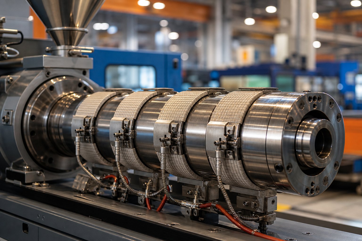
Every plastic part starts as a handful of raw polymer pellets. Turning those pellets into a precise, repeatable product depends on one critical component: the injection molding barrel. It is the heated steel cylinder at the heart of the plasticizing unit, where solid resin is conveyed, compressed, melted, and homogenized into a uniform melt ready for injection into the mold cavity. Without a properly functioning barrel, no amount of machine tuning or mold optimization can save your part quality.
The barrel doesn't work alone. It operates as part of a tightly coordinated system — the plasticizing unit — alongside the reciprocating screw and the nozzle. Pellets enter from the hopper, and the screw rotates inside the barrel to move them forward, generating shear and friction that drive roughly 80-90% of the actual melting. Band heaters wrapped around the barrel's exterior supply supplemental heat and maintain precise temperature control across multiple zones. The molten polymer accumulates ahead of the screw tip, and when the screw rams forward, it pushes the melt through the nozzle and into the mold.
What Is an Injection Molding Barrel
At its core, the injection molding barrel is a precision-machined steel cylinder with extremely tight bore tolerances. It must endure a punishing combination of high temperatures (often exceeding 300 °C for engineering resins), intense pressures during injection, and constant contact with resin environments that may be abrasive, corrosive, or both. The bore's internal surface finish and dimensional accuracy directly determine how efficiently the screw can plasticize material and deliver consistent shots.
When you're evaluating or specifying a barrel, you'll encounter a handful of key terms that define its performance envelope:
- L/D Ratio — the length-to-diameter ratio of the barrel and screw assembly, typically ranging from 18:1 to 24:1 for general-purpose machines. It governs melting capacity, mixing quality, and residence time.
- Bore Diameter — the internal diameter of the barrel, which sets the balance between shot volume and available injection pressure. A small change in bore diameter has a large impact on capacity because shot volume scales with the square of the diameter.
- Plasticizing Capacity — the maximum weight of material the barrel and screw combination can melt per unit time, usually expressed in kg/hr.
- Shot Size — the maximum volume of melt the barrel can deliver in a single injection cycle, determined by bore area and injection stroke length.
These specifications are not independent — they interact. A higher L/D ratio improves melt homogeneity but increases residence time, which can degrade heat-sensitive polymers. A larger bore diameter boosts shot capacity but reduces maximum injection pressure. Understanding these trade-offs is the first step toward making informed barrel decisions.
Why the Barrel Matters for Part Quality
Imagine running a high-cavity mold producing thousands of precision components per shift. If the barrel bore has worn beyond tolerance, melt leaks backward past the screw flights, and suddenly your shot weight drifts from cycle to cycle. Parts come out with dimensional inconsistencies, surface streaks, or unmelted specks — defects that trace straight back to a barrel that can no longer do its job.
Barrel condition directly controls three pillars of injection molding performance: melt homogeneity (uniform temperature and viscosity throughout the shot), shot-to-shot consistency (repeatable volume and pressure delivery), and final part dimensional accuracy (stable shrinkage and packing behavior). When any of these pillars weakens, scrap rates climb, cycle times stretch, and per-part costs rise.
The barrel is one of the most capital-intensive consumable components on an injection molding machine. Unlike the mold, which can run for millions of cycles, the barrel wears with every shot — and understanding its engineering is essential to controlling per-part cost.
This article covers the full engineering picture: construction materials and lining technologies, barrel sizing and shot capacity calculations, heating systems and temperature control, resin-to-barrel compatibility, wear mechanisms and early detection, maintenance and purging procedures, and replacement decision criteria. Whether you're a process engineer optimizing a cell, a maintenance technician diagnosing wear, or a manager evaluating replacement quotes, each section builds on the last to give you a practical, data-informed resource.
The construction material lining the barrel's bore is the first — and arguably most consequential — decision that determines how long it will survive your specific resin environment.
Barrel Construction Materials and Lining Technologies Compared
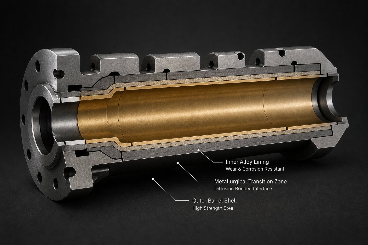
Your barrel's bore surface is the front line. It is the only thing standing between your resin — which may be abrasive, corrosive, or both — and the structural steel that holds everything together. Choose the wrong lining technology for your application, and you'll watch bore tolerances deteriorate in months instead of years. Choose correctly, and you'll get predictable performance across tens of thousands of operating hours.
Three primary injection molding barrel lining types dominate the market, each engineered for a different level of punishment. Understanding how they compare — nitrided vs bimetallic and beyond — is the foundation for every barrel specification decision you'll make.
Nitrided Steel Barrels
A nitrided barrel starts as a single piece of nitriding-grade alloy steel, most commonly 38CrMoAlA or equivalent grades like EN-41B and Nitralloy 135M. The barrel is machined to final dimensions, then placed in a gas or plasma nitriding furnace at 500-550 °C. Nitrogen atoms diffuse into the bore surface, creating a hardened case approximately 0.5-0.8 mm deep with surface hardness in the range of 950-1100 HV (roughly 65-70 HRC equivalent).
Beneath that hardened shell, the core steel retains its original toughness at around 280-320 HB. This combination delivers solid wear resistance for non-abrasive processing at a competitive price point.
Pros
- Lower upfront cost — typically half the price of a bimetallic equivalent
- Adequate wear resistance for unfilled commodity resins like PP, PE, ABS, and PS
- Good dimensional stability and fatigue strength
- Widely available with shorter lead times
Cons
- Thin hardened case (0.5-0.8 mm) offers no second chance — once abrasive wear penetrates the case, the soft core is exposed and wear accelerates rapidly
- Insufficient for glass-filled, mineral-filled, or ceramic-filled compounds
- Limited corrosion resistance against acidic off-gases from PVC or flame-retardant formulations
Think of it this way: a nitrided barrel is like armor with a hard outer coating but a soft interior. As long as nothing scratches through that coating, you're protected. The moment glass fibers or mineral particles cut past it, the underlying steel erodes fast and barrel life drops from years to months.
Bimetallic Lined Barrels
Bimetallic barrel lining for injection molding takes a fundamentally different approach. Instead of hardening the surface of a single steel, this technology bonds a separate wear-resistant alloy liner to the barrel bore through centrifugal casting at approximately 1100 °C. The barrel shell rotates at controlled speed while molten alloy is introduced, creating a metallurgical bond between the liner and the outer steel. The resulting liner thickness ranges from 1.5 mm to 3.0 mm — three to six times the depth of a nitrided case.
Here's where it gets interesting. The alloy composition of that liner can be tailored to match the specific wear challenge your resin presents:
- Iron-based alloys (Fe-B-C) — Optimized for abrasion resistance. These are the workhorse choice for glass-filled nylons, mineral-filled compounds, and recycled streams with unpredictable contamination. Hardness typically reaches 58-65 HRC.
- Nickel-based alloys (Ni-Cr-B-W) — Engineered for corrosion resistance with good abrasion resistance as a secondary benefit. The best barrel material for processing PVC, CPVC, flame-retardant compounds, and halogenated polymers that release aggressive off-gases during melting.
- Cobalt-based alloys — Deliver balanced performance against both abrasion and corrosion at elevated temperatures, making them suitable for engineering thermoplastics processed at high barrel temperatures.
Because wear progresses through a homogeneous alloy with stable hardness — rather than a steep hardness gradient like a nitrided case — a bimetallic barrel degrades predictably. You'll notice gradual, measurable bore growth rather than sudden catastrophic wear once the hard layer is breached. This predictability makes maintenance planning far more reliable.
The trade-off? Cost. A bimetallic barrel typically runs 2-3x the price of a nitrided unit. However, in abrasive or corrosive applications, service life extends 3-5x longer, making the total cost of ownership significantly lower over a multi-year production horizon.
Specialized Linings for Extreme Applications
Some resin formulations push even bimetallic linings to their limits. Imagine processing a compound loaded with 40% ceramic filler or running highly corrosive fluoropolymers at extreme temperatures. Standard alloy liners won't survive long enough to justify their cost.
For these demanding scenarios, two advanced options exist:
- Tungsten carbide (WC) rich liners — These liners incorporate a high concentration of tungsten carbide particles within the alloy matrix, pushing hardness into the 65-75 HRC range. They represent the best barrel material for glass filled resin at high loading levels (30%+ glass fiber) and ceramic-filled engineering plastics. Field data from compounding operations shows WC-rich liners delivering stable bore geometry for over 36 months in applications where standard bimetallic liners lasted only 12-18 months.
- Powder metallurgy (PM) linings — Manufactured through hot isostatic pressing rather than centrifugal casting, PM linings achieve extremely uniform microstructures with fine carbide distribution. They excel in applications combining high abrasion with high corrosion, where the dual attack would compromise conventional cast liners.
These specialized options carry the highest price tier, but for the right application, they're the only responsible specification.
Injection Molding Barrel Lining Types Compared
The table below maps each lining technology against the performance characteristics and applications that matter most when specifying an injection molding barrel:
| Lining Type | Hardness Range | Abrasion Resistance | Corrosion Resistance | Cost Tier | Ideal Resin Applications |
|---|---|---|---|---|---|
| Nitrided (gas/plasma) | 950-1100 HV (surface) | Moderate | Low to Moderate | $ | Unfilled PP, PE, PS, ABS; standard commodity resins |
| Bimetallic — Iron-based (Fe-B-C) | 58-65 HRC | High | Moderate | $$ | Glass-filled nylon, mineral-filled compounds, recycled streams |
| Bimetallic — Nickel-based (Ni-Cr-B-W) | 58-62 HRC | Moderate to High | High | $$ | PVC, CPVC, flame-retardant formulations, halogenated polymers |
| Bimetallic — Cobalt-based | 55-62 HRC | Moderate to High | High | $$$ | High-temperature engineering resins, combined abrasion/corrosion |
| Tungsten Carbide (WC) Rich | 65-75 HRC | Very High | Moderate to High | $$$ | High-load glass fiber (30%+), ceramic-filled plastics |
| Powder Metallurgy (PM) | 60-70 HRC | Very High | Very High | $$$$ | Extreme dual wear: highly abrasive + highly corrosive compounds |
One pattern stands out in the data: the right lining choice depends entirely on what resin you're running and what it does to the bore. A nitrided barrel processing clean polyethylene can deliver five or more years of reliable service. That same barrel running 30% glass-filled nylon might not last eight months. The lining isn't just a material spec — it's a direct reflection of your process reality.
Choosing the correct lining, however, is only half the equation. Even a perfectly specified barrel will underperform if it's incorrectly sized for your shot weight and cycle time — a mismatch that quietly degrades resin inside the bore long before defects reach your parts.
Barrel Sizing and Shot Capacity Explained
Picture this: you've specified the perfect barrel lining, your screw geometry is matched to the resin, and part geometry looks solid. Yet parts come off the machine with discoloration, brittleness, or inconsistent dimensions. Quality control flags half the lot. What went wrong? The culprit is often hiding in plain sight — a mismatch between your shot size and barrel capacity that silently degrades resin before it ever reaches the mold.
Getting barrel capacity vs part weight right in injection molding isn't glamorous work, but it's one of the most impactful decisions you'll make. Too large a barrel for a small part, and the resin cooks. Too small, and you sacrifice process control. Here's how to navigate it.
Understanding Shot Size Utilization
There's a widely referenced guideline in the industry: your shot size should consume 25% to 65% of the barrel's maximum capacity. Injection molding expert John Bozzelli has revisited this principle multiple times because it's that important — and that often overlooked.
Why does this range matter? Think about it from the screw's perspective.
When you use less than 25% of barrel capacity, the screw barely rotates to recover the shot. Recovery time is short, screw rpm stays low, and the screw completes very few revolutions per cycle. Those few turns simply aren't enough for the screw to do its job — compressing, shearing, and mixing the granules into a homogeneous melt. Roughly 80% of the energy needed to melt plastic comes from mechanical shear generated by the screw, not from the barrel's heater bands. With minimal screw rotation, you're relying almost entirely on conductive heat transfer through the barrel wall, which produces a sluggish, uneven melt.
Worse, the resin sits in that heated barrel far longer than it should. Every extra second at elevated temperature invites thermal degradation — chain scission, oxidation, and off-gassing that weaken the polymer at the molecular level.
On the opposite end, using more than 65% of barrel capacity introduces a different set of problems. At large shot sizes, most of the screw flights in the feed zone end up behind the feed throat after recovery — meaning there are only a few flights available to pick up, compress, and prepare fresh pellets for the transition zone. Semi-crystalline resins like PP and PE are especially vulnerable here. Unlike amorphous materials that soften gradually (similar to butter melting), semi-crystalline polymers stay rigid until they hit their melt point, demanding roughly twice the energy input. With a truncated feed zone and insufficient preparation, these hard granules can literally grind metal off the screw flights, accelerating wear while delivering poor melt quality.
There's also a practical process control issue: oversized shots reduce the available cushion — the small pad of melt left in front of the screw after injection. Without adequate cushion, you lose the ability to apply consistent packing pressure, which directly affects part dimensions and weight consistency.
How Residence Time Connects to Barrel Selection
Residence time is the average duration a resin pellet spends inside the heated barrel, from the moment it enters the feed throat to the moment it's injected into the mold. It's a function of three variables: barrel volume, shot size, and cycle time.
The simplest way to estimate it? Divide the barrel's maximum shot capacity by your actual shot size to determine how many shots of material are sitting in the barrel at any given moment, then multiply by the cycle time. For example, a machine with a 12-inch maximum shot running a 1.5-inch actual shot at a 15-second cycle yields a residence time of about 2 minutes — which falls within the commonly accepted 2-to-5-minute target.
However, that basic calculation underestimates reality. It ignores the material being conveyed within the screw's feed, compression, and metering zones — plastic that hasn't yet accumulated ahead of the screw tip but is still experiencing heat exposure. Industry references from Olmstead and Davis suggest applying a barrel factor (typically 1.4 for stroke lengths of four or more diameters) to account for this additional inventory. Using the same example, the adjusted residence time jumps from 2 minutes to approximately 2.8 minutes.
One easily missed detail: barrel capacities are typically specified in ounces or grams of general-purpose polystyrene (GPPS). If you're molding a different material, you need to convert using melt density — not specific gravity. Polypropylene, for instance, has a lower melt density than GPPS, so a 60-ounce barrel actually holds only about 46.4 ounces of PP. Skipping this conversion leads to scheduling errors, inaccurate utilization percentages, and sometimes even short shots when the machine simply can't deliver enough material.
Why does residence time matter so much? Heat-sensitive resins punish you quickly for getting it wrong. PVC releases hydrochloric acid when it degrades — corroding the barrel bore while ruining parts. POM (acetal) decomposes to formaldehyde gas at extended exposure. PBT and certain engineering thermoplastics develop discoloration, embrittlement, and molecular weight loss. Even common resins like PP can yellow and lose impact strength with excessive heat history. In every case, the damage is cumulative and often invisible until parts fail downstream testing.
Matching Barrel Capacity to Part Weight
So how do you perform an injection molding barrel shot size calculation correctly? Rather than guessing or accepting whatever machine happens to be available on the floor, use a systematic approach:
- Determine the total shot weight. Add the part weight (all cavities) to the runner and sprue weight. If you're running a hot-runner mold, include only the cold slug or vestiges.
- Convert barrel capacity to your specific resin. Multiply the machine's rated shot capacity (in GPPS) by the ratio of your resin's melt density to the melt density of GPPS (approximately 0.97 g/cm3). This gives you the true usable capacity for your material.
- Calculate utilization percentage. Divide total shot weight by adjusted barrel capacity and multiply by 100. Your target is 25-65%. For heat-sensitive resins, aim for 40-65% to minimize residence time. For amorphous resins with forgiving thermal windows, the lower end of the range is more acceptable.
- Estimate residence time. Use the formula: (Maximum shot capacity / Actual shot size) x Cycle time x Barrel factor. Compare the result against your resin manufacturer's recommended maximum residence time.
- Cross-reference with available screw diameters. If the utilization percentage falls outside the target range, evaluate a different screw and barrel combination on the same machine (if available) or reassign the mold to a machine with a more appropriate barrel size.
This process sounds straightforward, but in production environments, it rarely gets done systematically. Molds are assigned to machines based on tonnage and availability, not barrel capacity match. The result? An oversized barrel running a small medical component at 12% utilization — baking resin for 8 minutes when the material datasheet warns against exceeding 4. Or a tight-tolerance automotive part crammed into a machine at 80% utilization, where inconsistent cushion and poor melt quality chase operators through constant adjustments.
Barrel sizing errors are one of the most common causes of degradation-related defects in injection molding. A mold assigned to the wrong machine doesn't just produce bad parts — it accelerates barrel wear, wastes material, and creates troubleshooting loops that consume engineering hours without ever addressing the root cause.
Getting the barrel-to-part match right is a prerequisite for stable production. But even a perfectly sized barrel can't deliver consistent melt quality if the heat that maintains it is unreliable — which is exactly where heater band selection and temperature zone strategy come into play.
Barrel Heating Systems and Temperature Control Strategies
A perfectly sized barrel loaded with the correct lining still depends on one thing to function: reliable, uniform heat delivery. The heater bands wrapped around your injection molding barrel are the unsung workhorses of the plasticizing system. When they perform well, nobody notices. When they degrade, fail, or underperform, the symptoms disguise themselves as material problems, screw wear, or process instability — sending technicians chasing ghosts for hours.
Yet despite their critical role, injection molding barrel heater band types rarely get the engineering attention they deserve. Most operators inherit whatever heaters came with the machine and replace them with identical units when they burn out. That approach misses an opportunity. Different heater technologies deliver dramatically different thermal performance, energy consumption, and service life — and the choice directly affects how well your barrel temperature zones actually control melt quality.
Types of Barrel Heaters
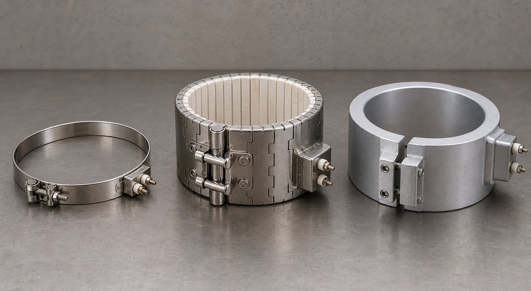
Three primary heater technologies dominate the injection molding market. Each transfers thermal energy to the barrel wall through a different physical mechanism, and each carries distinct trade-offs in cost, efficiency, and durability.
Mica band heaters are the industry's default. They rely on pure thermal conduction: a nickel-chromium (NiCr) resistance wire wound around a phlogopite mica core, sandwiched inside a stainless steel sheath. Heat travels from the wire through the mica insulator, through the sheath, and into the barrel — a chain that demands flush, metal-to-metal contact at every link. Their ultra-thin profile (typically 3-5 mm) makes them ideal for tight clearance installations, and they heat up fast due to low thermal mass. The downside? Mica heaters are uninsulated, meaning roughly half of the generated heat radiates outward into the shop air rather than inward toward the polymer. They also hit a hard physical ceiling: maximum operating temperature of approximately 340 °C and a maximum watt density of 3 W/cm2. Push past either limit, and the organic binders in the mica sheets carbonize and become electrically conductive, causing the heater to arc to ground and fail.
Ceramic band heaters operate on a fundamentally different principle. Internal resistance coils thread through interlocking steatite ceramic knuckles that transfer heat via both conduction and far-infrared radiation. This dual mechanism means ceramic heaters don't require the flawless barrel contact that mica elements demand — a significant advantage in real-world production where barrel surfaces are rarely pristine. A built-in 12 mm ceramic fiber insulating blanket between the heating elements and the outer sheath acts as a thermal directional barrier, forcing energy inward toward the polymer rather than outward into the factory. The result? Factory audits consistently demonstrate 25-30% lower energy consumption compared to mica heaters on the same machine. Ceramic bands safely operate up to 600 °C with watt densities reaching 6 W/cm2 — making them the only viable option for processing high-temperature engineering resins like PEEK, PPA, and high-temperature nylons.
The trade-offs? Ceramic heaters add roughly 12 mm of thickness to the barrel profile, require a minimum inner diameter of 60 mm, and carry a higher upfront cost. Their steatite tiles are also brittle — excessive hammering during installation or dropping a heater onto concrete will fracture internal tiles and lead to premature short circuits. Heat-up response is also slightly slower than mica due to higher thermal mass, though this difference is negligible in production cycling.
Cast aluminum heaters take yet another approach. A tubular heating element is literally cast into a custom-machined aluminum body that matches the barrel's exact outer diameter. This eliminates air gaps entirely, creating the highest possible thermal contact between heater and barrel. The aluminum body distributes heat with exceptional uniformity, minimizing hot spots and temperature gradients along the zone. Cast aluminum heaters are the most durable option mechanically and thermally, but they are also the most expensive and least flexible — each unit is manufactured to a specific barrel diameter and zone length, making them impractical for standardized inventory and less common outside precision applications where melt temperature uniformity is absolutely critical.
The following table summarizes the comparison across the performance dimensions that matter most when selecting heaters for your injection molding barrel:
| Heater Type | Heat Transfer Efficiency | Energy Consumption | Durability | Typical Use Case |
|---|---|---|---|---|
| Mica Band | Moderate — relies on pure conduction; sensitive to air gaps | High — no insulation; significant outward heat loss | Shorter lifespan (1-2 years typical); vulnerable to contamination and loose clamping | General-purpose resins (PP, PE, ABS) below 300 °C; space-constrained installations; cost-sensitive operations |
| Ceramic Band | High — conduction plus far-infrared radiation; tolerant of minor air gaps | Low — built-in insulation reduces consumption by 25-30% | Long lifespan (3-5 years under proper handling); susceptible to impact damage from rough installation | Engineering resins (PEEK, PA, PPA); 24/7 production lines; energy-conscious facilities; barrel temps above 340 °C |
| Cast Aluminum | Very High — zero air gap; superior thermal uniformity across the zone | Low to Moderate — excellent thermal contact minimizes wasted energy | Longest lifespan; mechanically robust; resistant to contamination ingress | Precision molding; tight melt-temperature tolerance applications; medical and optical components |
When evaluating ceramic vs mica band heater options for injection molding, the decision often comes down to processing temperature and production intensity. For a shop running commodity resins on intermittent schedules below 300 °C, mica heaters deliver adequate performance at minimum cost. For continuous production with engineering thermoplastics — or any operation where energy costs and thermal stability matter — ceramic heaters typically reach a break-even point within six months through reduced electricity consumption alone.
Barrel Temperature Zone Profile Setup
An injection molding barrel isn't heated uniformly. It is divided into multiple independently controlled heating zones — typically three to five, depending on barrel length — each monitored by its own thermocouple and regulated by a dedicated PID controller or SSR (solid-state relay). These zones span from the feed throat at the rear to the nozzle at the front, and the temperature setpoint assigned to each zone creates what's known as the barrel temperature profile.
The most common strategy is progressive temperature profiling: gradually increasing setpoints from the rear zone toward the nozzle. Zone 1 (feed) runs coolest to prevent pellets from melting prematurely and sticking to the barrel wall — a condition that starves the screw and causes surging. Zone 2 (compression) ramps up to support the primary melting occurring through screw shear. Zone 3 (metering) is set higher still to homogenize the melt and stabilize viscosity. The nozzle zone is often the hottest or matches Zone 3, ensuring smooth flow into the sprue bushing without cold slugs or premature freeze-off.
This "standard ramp" profile works well for most commodity and general-purpose resins — PP, PS, ABS, and HDPE all respond predictably to gradual thermal escalation. However, not every resin behaves the same way:
- Flat profiles — all zones set at or near the same temperature — suit shear-sensitive materials like PC, PMMA, and some TPUs. These polymers generate most of their melt energy from mechanical shear, so the barrel simply needs to maintain a stable, uniform thermal environment without creating temperature-driven viscosity swings.
- Reverse profiles — Zone 1 hottest, decreasing toward the front — address feed-zone challenges with high-viscosity resins, tacky pellets, or slippery nylons (PA6/PA66) that struggle to convey consistently. A hotter rear zone improves pellet traction and prevents the screw starvation that manifests as surging and inconsistent shot weight.
Here's the critical connection that most temperature control discussions overlook: your temperature profile is only as good as the heater hardware delivering it. A ceramic band heater maintaining Zone 2 at 260 °C delivers that setpoint with tight uniformity across the zone surface, minimal thermal cycling, and stable PID behavior. A worn mica heater on the same zone — loose on the barrel, with degraded insulation and inconsistent contact — might display 260 °C on the controller while actual barrel-wall temperature fluctuates by 15-20 °C within each PID cycle. The controller reads an average, but the polymer experiences alternating hot and cold spots that produce viscosity variations, inconsistent melting, and shot-to-shot drift.
This is why barrel temperature zone profile setup must account for heater condition, not just setpoint numbers. The most sophisticated temperature strategy in the world accomplishes nothing if the hardware delivering the heat can't execute it faithfully.
Diagnosing Heater-Related Melt Problems
Heater band degradation rarely announces itself with a sudden machine alarm. Instead, it creeps in as subtle process drift — symptoms that mimic other problems and send technicians down the wrong diagnostic path. You'll notice cycle times gradually stretching as the controller compensates for weakening heat output. Parts start showing occasional unmelted pellets or cold slugs, seemingly at random. Melt temperature readings swing between shots despite identical setpoints. Color consistency deteriorates. Back pressure climbs as the screw works harder to compensate for uneven thermal conditions.
These symptoms often get blamed on material variation, screw wear, or moisture — legitimate causes in their own right, but ones that should only be diagnosed after heater performance has been verified. A single failed or degraded band heater creates a cold zone on the barrel that disrupts the entire melting profile. Resin passing through that zone doesn't reach target temperature, arriving at the metering section partially unmelted and at inconsistent viscosity. The downstream zones can't fully recover the deficit, and the resulting melt quality problems cascade into the mold.
The most dangerous failure mode? A solid-state relay stuck in the closed position. When an SSR fails "on," it continuously delivers full power to the heater band regardless of the controller's output signal. The zone overheats, the resin degrades, and the controller display may still show the correct setpoint — because the thermocouple reads the barrel wall average, masking the localized overheating that's destroying your polymer.
To catch heater-related issues before they become quality problems, process technicians should perform regular inspections using this checklist:
- Visual inspection for discoloration: Rainbow or blue-purple annealing marks on the outer sheath indicate the heater overheated due to poor barrel contact or air gaps. Replace the heater and clean the barrel surface to bare metal before reinstalling.
- Contact verification: Check that each band sits flush against the barrel with no visible gaps. Use a feeler gauge if necessary. Re-torque clamping hardware after the machine reaches operating temperature to compensate for thermal expansion (the "hot re-torque" practice).
- Amperage draw measurement: Use a clamp meter to check current draw on each heater circuit. Uneven amperage between zones of similar wattage rating indicates a failing heater element, a bad SSR, or a loose connection.
- Thermocouple seating check: Confirm that all thermocouples are firmly seated in their wells and making solid contact. A loose thermocouple reads ambient air temperature rather than barrel wall temperature, causing the controller to overdrive the heater — a direct path to element burnout and resin degradation.
- Resistance (ohms) test on suspect heaters: Disconnect power and measure resistance across the heater leads with a multimeter. An "OL" (open loop) reading confirms a broken internal wire. A reading significantly lower than the heater's rated resistance suggests a partial short circuit.
- Contamination and leak check: Inspect for evidence of polymer leakage, hydraulic oil, or moisture around heater seams. Carbonized plastic residue inside a heater's seams is the leading cause of dielectric breakdown and sudden short-circuit failure.
- SSR output verification: With the zone at setpoint and the controller commanding zero output, verify that no current flows to the heater. Any current draw indicates a failed relay stuck in the closed position — replace immediately.
- Cycle time and PID behavior monitoring: Track heater ON-time percentages through the controller. A heater zone that stays energized significantly longer than adjacent zones of similar thermal load is either losing efficiency, making poor barrel contact, or approaching end of life.
Building this inspection into a routine maintenance schedule — monthly for high-utilization machines, quarterly for lighter production — catches degradation patterns early. A $30 mica band that fails undetected can easily generate $2,000 or more in downtime, scrap, and troubleshooting labor. Proactive heater management is one of the highest-ROI maintenance practices available on any injection molding machine.
Heater performance ensures the barrel delivers the right thermal environment — but the barrel's bore surface faces a completely different kind of threat from the resin itself. Different polymer families attack the barrel through abrasion, corrosion, or both, and matching barrel material to resin chemistry is what separates predictable service life from premature failure.
Resin-to-Barrel Compatibility and Material Selection Matrix
Your injection molding barrel doesn't fail randomly. It fails because the resin running through it attacks the bore surface in ways the barrel material wasn't designed to handle. Every polymer presents a specific wear profile — some grind metal away mechanically, some dissolve it chemically, and some do both at once. Matching barrel lining to resin chemistry is the single most consequential specification decision for barrel longevity. Get it right, and you'll measure service life in years. Get it wrong, and you'll be pulling the screw for bore inspection within months.
The resin-to-barrel compatibility chart below is designed to serve as a practical reference for engineers and maintenance teams making material selection decisions. But first, you need to understand the two fundamental mechanisms driving the damage.
Why Resin Chemistry Dictates Barrel Material
Resins destroy barrel surfaces through two distinct pathways, and recognizing which one dominates your application determines everything about how you specify the bore lining.
Abrasion is the more intuitive mechanism. Glass fibers, mineral fillers like calcium carbonate and talc, and ceramic particles are physically harder than barrel steel. As the screw conveys and shears the melt, these particles act like liquid sandpaper — dragging across the bore surface millions of times per production run. The damage is cumulative and measurable: bore diameter gradually increases, screw-to-barrel clearance widens, and plasticizing efficiency drops. Glass fiber is the most common abrasive culprit because it's used so widely, but mineral-filled and ceramic-filled compounds can be equally destructive depending on particle hardness and loading percentage. Industry experience consistently shows that once glass fiber content exceeds 15%, a nitrided barrel's service life drops dramatically compared to a bimetallic alternative.
Corrosion works differently — and more insidiously. Certain polymers release aggressive chemical byproducts during processing, typically as acidic or halogenated off-gases. PVC is the textbook example: at processing temperatures, PVC sheds hydrochloric acid (HCl) that attacks ferrous barrel surfaces through pitting and intergranular corrosion. Fluoropolymers like PVDF and PTFE release hydrofluoric acid (HF), which is even more aggressive. Flame-retardant compounds — particularly those using brominated or chlorinated additives — generate their own cocktail of corrosive decomposition products. Unlike abrasive wear, corrosion doesn't require physical contact with hard particles. It's a chemical reaction between the off-gas and the metal itself, creating localized craters and pitting that weaken the bore surface from within.
Here's what makes barrel material selection especially challenging: many real-world compounds present both challenges simultaneously. Imagine a 30% glass-filled PA66 with a brominated flame-retardant package. The glass fibers grind the bore mechanically while the flame-retardant decomposition products attack it chemically. A barrel lining optimized for abrasion alone won't survive the corrosion. A lining optimized for corrosion alone won't resist the glass. You need a lining that handles the combined assault — and that's exactly where the compatibility matrix earns its value.
Resin-to-Barrel Compatibility Matrix
The following table maps common resin families to their recommended barrel lining, typical processing temperature ranges, and special considerations. Use it as a starting point for specification decisions, then refine based on your specific filler package, production volume, and cost targets.
| Resin Family | Recommended Barrel Lining | Processing Temp Range | Primary Wear Mechanism | Special Notes |
|---|---|---|---|---|
| Unfilled commodity resins (PP, PE, PS, ABS) | Nitrided steel (38CrMoAlA or equivalent) | 180-260 °C | Minimal — adhesive wear only | Nitrided barrels deliver excellent cost-to-life ratio; bimetallic unnecessary for clean, unfilled grades |
| Engineering resins — unfilled (PA6, PA66, POM, PC) | Nitrided steel or iron-based bimetallic | 220-320 °C | Low abrasion; POM presents mild corrosion risk from formaldehyde off-gas | POM requires careful residence time control; PC is shear-sensitive — avoid excessive screw speed |
| Glass-filled nylons (PA6-GF, PA66-GF) and PBT-GF | Iron-based bimetallic (Fe-B-C) or tungsten carbide rich | 250-300 °C | High abrasion from glass fibers | At 30%+ glass loading, WC-rich liners significantly extend bore life; screw must also be hardfaced |
| Mineral-filled compounds (talc-filled PP, CaCO3-filled PE) | Iron-based bimetallic | 190-260 °C | Moderate to high abrasion depending on filler hardness and loading | Talc is softer than glass but high loading levels (40%+) still cause significant wear over time |
| PVC and CPVC | Nickel-based bimetallic (Ni-Cr-B) or Hastelloy-lined | 160-210 °C | Corrosion — HCl off-gas attacks ferrous surfaces | Best barrel lining for PVC processing uses nickel-based alloys; Colmonoy 56 is a proven option; temperature control is critical to minimize degradation |
| Fluoropolymers (PVDF, FEP, ETFE, PFA) | Hastelloy C-276 or Inconel 625 lined; nickel-based bimetallic minimum | 230-400 °C | Severe corrosion — HF off-gas is extremely aggressive | Corrosion resistant barrel for fluoropolymer molding is non-negotiable; standard steel and iron-based linings fail rapidly; screw must also be corrosion-resistant (e.g., Hastelloy or nickel-alloy flight facing) |
| Flame-retardant formulations (brominated PA, FR-PC/ABS, FR-PBT) | Nickel-based or cobalt-based bimetallic; powder metallurgy for combined glass + FR | 240-310 °C | Corrosion from halogenated off-gases; abrasion if glass-reinforced | Dual-attack compounds demand linings with both corrosion and abrasion resistance; PM linings justified for high-volume production of glass-filled FR resins |
A few patterns emerge from this matrix. Unfilled commodity resins are forgiving — a standard nitrided barrel handles them comfortably for years. The moment fillers or aggressive chemistries enter the picture, the barrel material for glass filled nylon, PVC, or fluoropolymer applications shifts to bimetallic or specialty linings, and the cost difference pays for itself through extended service intervals. The worst financial mistake isn't buying an expensive lining — it's buying a cheap one for the wrong application and replacing it three times in the span a proper lining would have lasted.
Matching Barrel and Screw Materials Together
One detail that frequently gets overlooked: barrel lining and screw surface treatment must be specified as a coordinated system, not as independent components. If you install a hard, wear-resistant bimetallic barrel but pair it with a soft, nitrided-only screw, the screw flights wear preferentially. Clearance between the screw OD and the barrel bore increases — not because the barrel failed, but because the screw couldn't keep up. The result is identical to barrel wear: backflow past the flights, loss of plasticizing efficiency, and declining shot consistency.
The reverse scenario is equally problematic. A screw with extremely hard flight tips (say, tungsten carbide hardfacing at 70+ HRC) paired with a softer barrel lining can actually cut into the bore, creating grooves and accelerating barrel wear. The goal is balanced wear — both components degrading at roughly the same rate so they can be replaced together on a predictable schedule.
For abrasive applications like glass-filled nylons, a common and effective pairing is an iron-based bimetallic barrel with a screw hardfaced using Colmonoy 83 or a similar nickel-tungsten carbide alloy on the flight lands. For corrosive applications, a nickel-based barrel lining paired with a stainless steel or Hastelloy-clad screw provides coordinated chemical resistance. The key principle is straightforward: never let one component dramatically outclass the other in hardness or corrosion resistance, because the weaker link will fail first and drag process quality down with it.
Running abrasive resins through a nitrided-only barrel is one of the fastest paths to bore wear and shot quality loss. A nitrided surface case of 0.5-0.8 mm offers no safety margin — once glass fibers cut through it, the soft core beneath erodes at several times the initial rate, and bore diameter can blow past tolerance within weeks.
Selecting the right barrel and screw material combination sets the stage for long service life — but materials alone don't tell the full story. Even the best lining will eventually wear, and understanding exactly how that wear progresses, what accelerates it, and how to catch it early is what separates reactive maintenance from proactive barrel management.
Barrel Wear Mechanisms and How to Detect Them Early
You've matched your barrel lining to the resin, coordinated the screw surface treatment, and dialed in your temperature profile. Everything is specified correctly on paper. Yet bore diameter still grows, shot consistency still drifts, and eventually parts start failing quality checks. Why? Because wear isn't a question of if — it's a question of how, where, and how fast. Understanding the specific injection molding barrel wear causes at work in your process is the difference between catching a problem at $500 and catching it at $50,000.
Most engineers think of wear as a single phenomenon. In reality, three distinct mechanisms attack the barrel bore — often simultaneously — and each demands a different diagnostic and preventive response.
Three Types of Barrel Wear
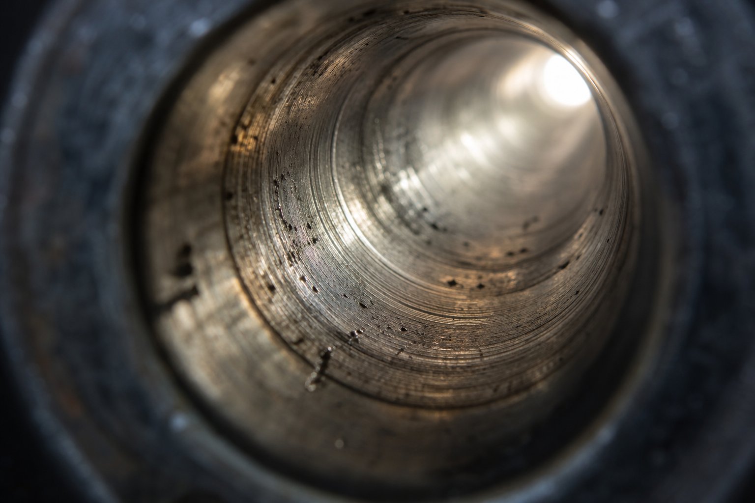
Abrasive wear is the most straightforward. Hard particles embedded in the polymer melt — glass fibers, mineral fillers like calcium carbonate and talc, ceramic microspheres, even pigment agglomerates — physically scrape material off the bore surface as the screw conveys and shears the melt. Think of it as liquid sandpaper running at high pressure against the barrel wall, millions of cycles per year. The damage is proportional to particle hardness, particle concentration, melt pressure, and screw speed. Glass fiber and calcium carbonate are the most common culprits, but any compound with hard additives above 10-15% loading will generate measurable abrasive wear over time. The wear pattern typically concentrates in the transition and metering zones, where pressures are highest and the melt carries particles at the greatest velocity against the bore.
Corrosive wear operates through an entirely different pathway. Instead of physically removing metal, aggressive chemical byproducts released during resin processing attack the bore surface at the molecular level. PVC sheds hydrochloric acid. Fluoropolymers release hydrofluoric acid. Flame-retardant compounds with brominated or chlorinated additives generate their own corrosive cocktail. These off-gases don't need hard particles to do damage — they pit, crater, and dissolve the barrel's metallic surface from within. Corrosive wear tends to be most severe in the metering zone, where temperatures peak and material has been exposed to heat the longest, maximizing the opportunity for polymer degradation and off-gas generation.
Adhesive wear is the least intuitive — and often the most preventable. It occurs when the screw flight crests physically contact the barrel bore, creating momentary micro-welds between the two metal surfaces. As the screw continues rotating, these tiny welds are immediately torn apart, ripping small fragments from one or both surfaces. Bausano's engineering team describes it as a sort of small weld originated and immediately removed by rotation — a rapid, repetitive cycle of bonding and tearing that roughens surfaces and generates metallic debris that contaminates the melt. Adhesive wear is almost always caused by misalignment, screw deflection, or insufficient clearance between the screw OD and bore ID.
Here's the critical insight most troubleshooting guides miss: real-world wear is almost never a single mechanism acting alone. A glass-filled flame-retardant nylon, for example, delivers abrasive attack from the glass fibers and corrosive attack from the halogenated off-gases and adhesive wear if the heavy, filled melt causes screw deflection. These mechanisms interact synergistically — corrosion roughens the bore surface, which accelerates abrasive particle catch, which widens clearance, which increases screw deflection, which introduces adhesive contact. The three mechanisms feed each other in a self-reinforcing loop that can accelerate wear far beyond what any single mechanism would predict in isolation.
How Barrel Misalignment Accelerates Wear
Imagine a screw spinning inside a barrel bore that isn't perfectly concentric. Instead of floating centered in the melt — held in place by the hydrodynamic pressure of the polymer film surrounding it — the screw rides against one side of the bore. That localized contact creates a barrel screw misalignment wear pattern: a crescent-shaped zone of accelerated material removal on one side of the bore while the opposite side remains relatively untouched.
This asymmetric wear is devastating because it progresses exponentially. As the contact side wears, clearance increases unevenly. The screw deflects further into the worn zone. Contact pressure intensifies. The wear rate climbs. What starts as a few thousandths of an inch of bore deviation can balloon into a visibly oval bore cross-section within a few months of continuous production.
Several factors contribute to misalignment, and most of them develop gradually enough to escape routine observation:
- Improper barrel support: The barrel must be supported at designed intervals to prevent sagging under its own weight plus the filled melt. Missing or damaged support brackets — especially on long-L/D barrels — allow the barrel to bow, creating a curvature mismatch with the straight screw.
- Thermal expansion without adequate clearance: A steel barrel expands significantly at operating temperature. If mounting hardware constrains that expansion unevenly, the barrel bows or shifts off-center. Proper barrel mounting uses fixed-point plus sliding-point supports to accommodate thermal growth.
- Worn thrust bearings: The thrust bearing assembly absorbs the axial force generated during injection. As it wears, axial play increases, allowing the screw to wobble during rotation. That wobble translates directly into cyclic bore contact.
- Bent or damaged screws: A screw that isn't perfectly straight creates its own misalignment. Rolling the screw on a granite table and checking for bowing with feeler gauges is a simple but essential inspection step that catches this problem before it destroys the barrel.
The practical lesson? Alignment isn't a one-time factory setting. It's a dynamic condition that changes with thermal cycling, mechanical wear, and maintenance interventions. Every time a screw is pulled and reinstalled, alignment should be verified. Every time thrust bearing play is checked, barrel concentricity should be confirmed as part of the same procedure.
Recognizing Wear Symptoms Before Part Quality Fails
The most expensive barrel failures aren't the dramatic ones — a cracked barrel or a catastrophic seizure shuts the machine down immediately, and the cause is obvious. The costly failures are the slow ones, where bore wear creeps past tolerance over weeks or months while parts gradually drift toward the edge of specification. By the time defects become visible in molded components, significant bore damage has already occurred, and the window for a cost-effective repair may have closed.
Here are the progressive warning signs of a worn injection molding barrel, listed roughly in the order they typically appear:
- Gradually increasing cycle times: As bore clearance widens, more melt leaks backward past the screw flights during recovery. The screw must rotate longer to accumulate the same shot volume ahead of the tip, stretching recovery time and, consequently, overall cycle time.
- Declining shot weight consistency: Wider clearance means less efficient pressure transmission during injection. Shot-to-shot weight variation increases — often by just a few tenths of a gram initially, easily missed without SPC monitoring, but steadily worsening.
- Visible streaking or color inconsistency in parts: Uneven melt homogeneity caused by melt leaking back through worn clearances and remixing with fresh material produces color streaks, swirl marks, and inconsistent surface gloss — especially noticeable during color changes or when running transparent or light-colored resins.
- Increasing back pressure required to maintain cushion: Operators compensate for declining plasticizing efficiency by raising back pressure. If the process log shows a gradual back-pressure creep over weeks without a material change, barrel wear is a prime suspect.
- Material leaking past the non-return valve: The non-return valve (check ring) at the screw tip relies on a tight seal against the barrel bore to prevent backflow during injection. A worn bore widens this critical sealing interface, allowing melt to slip past even a new check ring — a problem that no amount of valve replacement will fix if the root cause is the bore itself.
- Increased energy consumption: The screw motor works harder to overcome the efficiency losses from backflow and poor pressure buildup. Running costs climb as the drive compensates for what the worn barrel can no longer deliver mechanically.
- Appearance of black specks or degraded material: Widened clearance zones create stagnant pockets where resin hangs up, overheats, and carbonizes. These degraded particles eventually flush into the melt stream and appear as black specks, burn marks, or brown streaks in finished parts.
Notice the pattern: the earliest symptoms are subtle process metrics — cycle time, shot weight variance, back pressure trends — that only show up in data. By the time you see surface defects on parts, bore wear has already advanced well past the early-intervention stage. This is exactly why routine bore measurement using a bore gauge, recorded and compared against previous values, is the gold standard for how to detect barrel bore wear early. A bore gauge reading takes minutes. Replacing a barrel takes days and thousands of dollars.
Proactive bore measurement on a scheduled basis is far less costly than reactive replacement after quality failures. By the time defective parts reach the sort table, the barrel has already been losing money — silently — for weeks or months.
The signs of a worn injection molding barrel are predictable and progressive. Catching them early requires discipline — scheduled inspections, documented measurements, and trend analysis rather than waiting for visible defects. Barrel wear cannot be reversed, but its progression can be managed, slowed, and planned around.
Slowing that progression depends heavily on what happens between production runs and during material changeovers — the maintenance routines and purging practices that either extend barrel life or quietly shorten it.
Barrel Maintenance and Purging Procedures That Extend Barrel Life
Wear is inevitable. Every shot grinds, corrodes, or stresses the bore surface a little more. But how fast that wear progresses — and how much production value you extract before replacement — depends almost entirely on what happens between production runs. A disciplined maintenance program doesn't reverse bore damage, but it dramatically slows its progression, prevents contamination-driven defects, and gives your maintenance team the data it needs to plan replacements instead of scrambling through emergency shutdowns.
Yet barrel maintenance is one of the most neglected areas in injection molding operations. Machines run until something goes wrong. Purging is done with whatever resin is handy. Bore measurements happen only when quality problems have already escalated. The result? Barrels that could have served four or five years get replaced in two — and the scrap generated along the way dwarfs the cost of the maintenance that would have prevented it.
Barrel Purging Best Practices
Purging serves a deceptively simple purpose: removing residual resin from the barrel during color changes, material changes, or shutdowns to prevent contamination and thermal degradation. In practice, though, how you purge matters just as much as whether you purge at all. A poorly executed purge wastes material, extends downtime, and can leave behind exactly the kind of residue it was supposed to eliminate.
Three primary approaches exist, each with distinct strengths:
Mechanical purging uses a harder or higher-viscosity resin to physically push out the softer resident material. Common examples include running HDPE or acrylic through a barrel that just finished processing a lower-viscosity resin like PP or PS. The stiffer purge material generates higher shear at the bore and screw surfaces, scrubbing residue through brute mechanical force. It's straightforward and inexpensive — but limited. Mechanical purging struggles with stubborn color pigments, carbon deposits baked onto metal surfaces, and residue trapped in dead spots behind the check ring and inside hot-runner manifolds.
Chemical purging compounds (CPCs) take a different approach. These are formulated products that combine a carrier resin with active cleaning agents designed to chemically loosen deposits, improve wetting at metal surfaces, and lift contamination that mechanical action alone can't dislodge. As Stoner Molding Solutions explains, the carrier resin's compatibility with the resident polymer, its viscosity behavior, and its thermal stability window all determine whether the purge genuinely cleans or simply pushes contamination around. A well-matched CPC can reach areas that straight resin cannot — screw root radii, check ring sealing surfaces, and stagnant melt pockets in the transition zone.
Combined approaches layer both methods: a mechanical flush to remove bulk material, followed by a chemical purge to address residual films and deposits, then a final flush with the incoming production resin to clear purge compound traces. This sequenced strategy delivers the most thorough cleaning but uses more material and time. It's justified for high-contrast color changes (dark to light or black to white), transitions between chemically incompatible resins, and pre-shutdown cleaning before extended idle periods.
So which method fits your situation? That depends on several factors:
- Resin sensitivity: Heat-sensitive materials like PVC and POM degrade quickly during extended purging. Use a thermally stable CPC and minimize purge cycles — prolonged barrel residence at elevated temperature does more harm than good.
- Color contrast between changeover materials: A transition from natural to natural barely requires purging at all. A transition from carbon black to medical-grade white demands the most aggressive chemical purging protocol you can deploy. Match your investment in purge material and time to the difficulty of the changeover.
- Temperature compatibility: The purge material must melt and flow cleanly at the barrel's current operating temperature. A purge that runs below its ideal melt behavior acts like a partial flush, leaving films behind. One that runs too hot degrades and becomes a new source of contamination.
- Cost per changeover: Virgin resin purging is cheap per pound but wasteful per changeover — you'll use far more material to achieve the same result a CPC delivers in a fraction of the volume. Industry experience consistently shows that high-quality CPCs achieve a lower net cost-to-purge despite their higher per-pound price, because they require less material and fewer cycles to reach a clean state.
One often-overlooked benefit: routine CPC use actually extends barrel and screw life. Carbon buildup and degraded polymer deposits act as insulation barriers on the bore surface, disrupting heat transfer and creating localized hot spots that accelerate both corrosive and adhesive wear. Removing those deposits on a regular schedule keeps the bore surface clean and thermally consistent — a direct line to cost savings that most operations never quantify.
Cleaning Schedules and Material Changeover Procedures
Knowing how to clean an injection molding barrel is only half the equation. Knowing when — and documenting what you find — turns reactive firefighting into a predictable maintenance discipline. A barrel maintenance schedule for injection molding doesn't need to be complicated, but it does need to be consistent.
Start with a tiered framework based on production activity:
Every material or color changeover: Purge the barrel completely using the appropriate method from the selection criteria above. Verify the purge is clean by examining extruded material for color contamination, specks, or discoloration before introducing production resin. Document the changeover — incoming resin, outgoing resin, purge type used, number of purge cycles, and any anomalies observed. This log becomes invaluable for troubleshooting contamination issues that surface hours or days later.
Pre-shutdown procedures: Never leave corrosive or filled resins sitting in a hot barrel during idle periods. PVC, fluoropolymers, and flame-retardant compounds continue releasing corrosive off-gases even as the barrel cools, attacking the bore surface while no production value is being generated. Reiloy USA recommends always removing corrosive and filled resins before idling equipment. Purge with a clean, thermally stable compound — some CPCs are specifically formulated to seal the barrel during shutdown, preventing oxidation and the black-speck contamination that plagues startups.
Startup cleaning: After extended shutdowns (anything longer than a weekend), purge the barrel before introducing production resin. Resin left in the barrel during downtime oxidizes and degrades, even at ambient temperature if the barrel retains residual heat. Run purge material through until the extrudate is clean, clear, and free of specks or discoloration.
Periodic bore measurement intervals: This is where your barrel maintenance schedule ties directly to your resin's abrasiveness. When running primarily reinforced or filled resins, set up a PM program for inspecting every six months until wear trends have been established. For unfilled resins, annual inspection is a reasonable starting frequency. Once you've accumulated enough data points to chart a wear trend — typically three to four measurement cycles — you can extrapolate when the bore will approach tolerance limits and schedule replacement proactively rather than reactively.
Documentation is the thread that ties all of this together. A maintenance log should track, at minimum: date of inspection, bore diameter readings at multiple points along the barrel length, screw OD measurements at corresponding locations, purge type and frequency since last inspection, resins processed and approximate production volume, and any process anomalies observed (cycle time drift, back pressure changes, cushion instability). Without this data, you're guessing. With it, you're managing.
Barrel Inspection Criteria and Replacement Indicators
Every injection molding barrel has a defined bore diameter tolerance — the maximum allowable increase in bore diameter beyond the nominal specification. This isn't an arbitrary number. It represents the point at which screw-to-barrel clearance becomes wide enough to cause measurable backflow past the screw flights, reducing plasticizing efficiency, shot weight consistency, and packing pressure control.
Typical barrel bore measurement tolerance limits vary by bore size, but a common industry guideline defines the boundary at approximately 0.05-0.10 mm (0.002-0.004 in.) of diametrical growth beyond nominal for most standard screw diameters. Davis-Standard's maintenance guidelines provide tiered wear categories — low, medium, and high — for various screw diameters, where low wear may only cause a slight decrease in output, medium wear signals planning for rebuild or replacement, and high wear demands immediate action. The same principle applies to barrel bores: once you've crossed into the "high" range, no amount of process adjustment compensates for the lost sealing efficiency between screw and bore.
When inspection reveals bore wear approaching or exceeding tolerance, you face a cost-benefit decision: rebore and reline, or replace the barrel entirely?
Reboring and relining involves machining the worn bore to a larger, uniform diameter and applying a new alloy lining through centrifugal casting. It's viable when the barrel's outer shell remains structurally sound — no cracks, no deformation, no excessive corrosion on external heating surfaces. Reboring typically costs 40-60% of a new barrel and extends service life by another full lining cycle. The trade-off is lead time (reboring requires removing the barrel from the machine and shipping it to a specialist) and the fact that you'll need a correspondingly oversized screw, since the new bore diameter will be larger than original.
Full barrel replacement makes sense when the shell itself is compromised, when multiple rebore cycles have already enlarged the bore past practical limits, or when the opportunity cost of extended downtime during reboring exceeds the price differential of a new unit. For high-utilization machines running abrasive materials, many operations keep a spare barrel on hand — ready to swap in during a planned shutdown while the worn barrel is sent out for evaluation.
Whether you're evaluating a rebore or a full replacement, the inspection itself should follow a structured procedure to ensure consistency and reliability of the data:
- Pull the screw and clean the barrel bore thoroughly. Use brass scrapers and copper gauze — never steel wire brushes or aggressive abrasive materials — to remove solidified polymer without scratching the bore surface. Residue left behind will give you false diameter readings.
- Allow the barrel to cool to room temperature. Thermal expansion at operating temperature adds several thousandths of an inch to the bore diameter. Measurements taken hot will overstate actual wear and lead to premature replacement decisions.
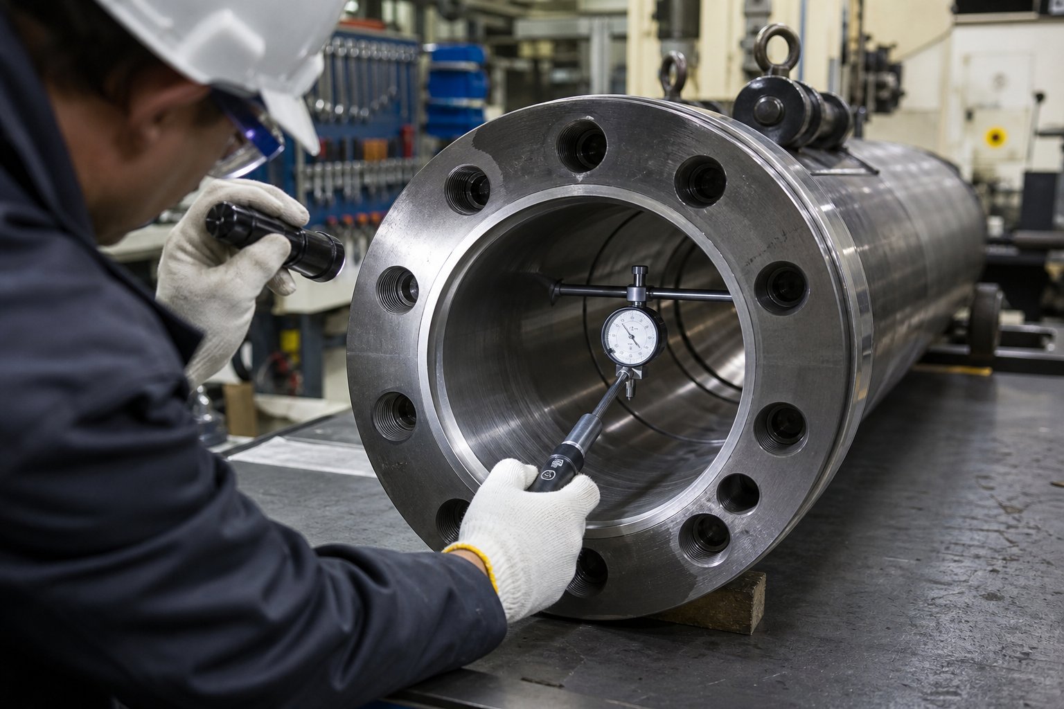
- Measure bore diameter at multiple points along the barrel length. Use a telescoping bore gauge or a purpose-built barrel bore gauge. Take readings at the feed zone entrance, mid-feed zone, transition zone, metering zone entrance, mid-metering zone, and near the nozzle seat. At each axial location, measure at two perpendicular orientations (0° and 90°) to detect oval wear patterns caused by misalignment.
- Record all readings and compare against nominal bore diameter and previous inspection data. Look for localized wear hot spots — a single point that's significantly more worn than adjacent zones often indicates a misalignment problem, a dead-spot corrosion pocket, or a damaged screw section that needs independent attention.
- Inspect the bore surface visually for pitting, scoring, and corrosion. Use a bore light or borescope. Smooth, uniform wear is normal and predictable. Pitting indicates corrosive attack. Scoring or grooves suggest abrasive particle embedding or screw-to-bore contact. These surface conditions inform whether a simple reline will suffice or whether deeper metallurgical evaluation is warranted.
- Measure the screw OD at corresponding axial locations. Combined barrel and screw measurements give you the true clearance picture. A barrel that appears within tolerance may actually be at effective end-of-life if paired with a significantly worn screw, because total clearance is the sum of both components' wear.
- Document findings, calculate wear rates, and project remaining service life. Divide total diametrical growth by the number of operating hours or production cycles since the last measurement. This wear rate — expressed in thousandths of an inch per thousand hours, for example — becomes the basis for forecasting when the barrel will reach replacement threshold and scheduling the changeover during a planned maintenance window.
This seven-step procedure takes a few hours during a scheduled screw pull. Skipping it to save time is a false economy — the data it generates is worth far more than the labor it consumes. Operations that track bore wear trends consistently report fewer unplanned shutdowns, lower scrap rates, and significantly better per-part cost control than those that wait for quality failures to trigger action.
Maintenance and inspection give you the data. The next question is what to do with it — specifically, when the numbers say it's time for a new barrel, how do you evaluate your options and choose the right supplier?
When to Replace Your Injection Molding Barrel and How to Choose a Supplier
Bore measurements are in. The data tells a clear story: clearance is widening, wear rates are accelerating, and process compensation is reaching its limits. You're standing at the decision point every maintenance team eventually faces — refurbish the existing barrel or replace it entirely? And if replacement is the call, where do you source the next one?
Both questions carry significant cost implications. A premature replacement wastes capital on a barrel that still had serviceable life. A delayed replacement bleeds money through scrap, extended cycle times, and the cascading efficiency losses described in earlier sections. The goal is a clear, data-driven framework that removes guesswork from the barrel refurbish vs replace decision and a practical set of criteria for evaluating suppliers who will deliver the right component on time.
When to Replace Versus Refurbish Your Barrel
The inspection procedure from the previous section gives you bore diameter readings, surface condition notes, and calculated wear rates. Translating that raw data into an actionable decision requires mapping each finding against the two available paths: refurbishment (reboring, relining, or both) and full replacement.
Refurbishment makes economic sense when the barrel's outer shell — the structural cylinder that carries the heating elements and mounts to the machine — remains dimensionally sound and free of cracks, warping, or external corrosion damage. If only the bore lining has worn past tolerance while the host steel is intact, a specialist can bore-grind the inner diameter to true roundness and straightness, then reline using centrifugal casting or hard chrome plating to restore the bore to serviceable condition. The cost typically runs 40-60% of a new barrel, and the restored unit can deliver another full lining cycle of production life.
Replacement becomes the better path when structural integrity is compromised, when the bore has already been rebored to the maximum allowable oversize, or when the barrel's metallurgy no longer matches the resin application — for example, a nitrided barrel that's been pressed into service on glass-filled compounds and needs to be upgraded to a bimetallic lining. Replacement also wins the cost-benefit analysis when lead time for refurbishment exceeds the production cost of extended downtime, particularly on high-utilization machines running 24/7.
Not every situation is clear-cut. The following table maps common condition indicators to the appropriate action and the reasoning behind each:
| Condition Indicator | Refurbish Option | Replace Option | Decision Guidance |
|---|---|---|---|
| Bore diameter 0.05-0.10 mm over nominal; uniform wear pattern | Rebore to next oversize and reline with original alloy type | Not required unless lining upgrade is desired | Refurbishment is cost-effective; pair with a matching oversized screw |
| Bore diameter exceeding 0.10 mm over nominal; localized hot spots | Possible if shell is sound and bore can be ground true | Recommended if wear pattern suggests misalignment damage to shell | Inspect shell concentricity; if shell is bowed or cracked, replacement is safer |
| Oval bore cross-section from misalignment wear | Rebore to round if ovality is within grinding range | Required if ovality has progressed beyond single-oversize correction | Horizontal boring machines can correct ovality if caught early enough; severe cases need a new barrel |
| Surface pitting or corrosion craters in bore | Reline with corrosion-resistant alloy (nickel-based) after bore grinding | Required if pitting extends beyond lining depth into base steel | Pitting confined to the lining layer is repairable; pitting into the shell steel compromises structural integrity |
| Barrel previously rebored to maximum oversize | Not viable — no material remaining for further enlargement | Full replacement required | Order replacement proactively once the barrel enters its final oversize cycle |
| External shell cracks, heat-check marks, or warping | Not recommended — shell integrity is compromised | Full replacement required immediately | A cracked shell risks catastrophic failure under injection pressure; do not attempt to refurbish |
| Application change requiring different lining metallurgy | Reline with upgraded alloy if shell is compatible | Replace if shell steel grade is incompatible with new lining process | Switching from nitrided to bimetallic requires the shell to accept centrifugal casting temperatures; verify with the manufacturer |
One practical consideration that often tips the scale: not all screw and barrel manufacturers are equipped for comprehensive refurbishment. The process demands specialized equipment — horizontal bore honing machines for correcting ovality, vertical bore grinding machines for achieving final bore size and surface finish, and PTA welding stations for screw flight restoration. Choosing a supplier without these capabilities means your "refurbishment" may be nothing more than a polish and a hope. Always verify that the refurbishment provider can demonstrate the precision grinding, concentricity correction, and metallurgical testing needed to return the barrel to a genuinely serviceable state.
What to Look for in a Barrel and Screw Supplier
Whether you're ordering a replacement barrel, a refurbished unit, or an upgraded screw-barrel combination for a new resin application, the supplier you choose determines far more than delivery date and price. A custom screw barrel manufacturer for injection molding should function as a technical partner — one that understands your specific machine, resin, and production demands well enough to recommend the right specification, not just fulfill a purchase order.
Here's what separates a reliable supplier from a parts catalog:
- Material certifications and metallurgical transparency. You should receive documented material certificates for every barrel and screw — steel grade, heat treatment records, lining alloy composition, and hardness test results. Tight tolerances, often within plus or minus 0.01 mm, ensure the screw and barrel work efficiently together without leakage or uneven wear. A supplier unwilling to provide this data is asking you to gamble on metallurgy you can't verify.
- Ability to supply custom screw geometries matched to specific resin applications. Standard general-purpose screws exist for a reason — they work acceptably across a range of common materials. But "acceptably" isn't the goal when you're processing glass-filled engineering resins, running high-speed thin-wall applications, or managing frequent color changes. The best suppliers offer custom barrier screw designs, application-specific compression ratios, and mixing element configurations tailored to your exact processing challenge.
- Availability of technical support for troubleshooting plasticizing issues. A barrel is not an isolated part — it's one element in a system that includes screw geometry, check ring design, temperature control, and resin behavior. When melt quality problems arise, you need a supplier who can diagnose whether the root cause is barrel wear, screw design mismatch, or process parameter error. Technical support that ends at "here's your tracking number" isn't support at all.
- Lead time reliability for replacement components. A worn barrel on a high-revenue machine costs money every hour it's waiting for a replacement. Suppliers who maintain inventory of common barrel blanks and screw sizes — or who can expedite custom orders within a predictable timeframe — directly reduce your exposure to unplanned downtime. Ask for realistic lead times upfront and verify them against the supplier's track record.
- Willingness to provide bore measurement and wear analysis services. Some suppliers offer on-site or mail-in inspection services where they measure your worn barrel and screw, analyze the wear pattern, and recommend refurbishment or replacement based on the data — not just their sales targets. This consultative approach builds trust and often catches issues (like misalignment-driven wear or lining-to-resin mismatches) that a simple reorder would perpetuate.
Manufacturers like NANHAIYA exemplify this partner-oriented approach, offering custom injection molding screw barrel solutions engineered for specific machine and resin combinations alongside technical support for diagnosing plasticizing performance issues. For maintenance teams sourcing replacement components or exploring upgraded barrel and screw configurations, their product line provides a practical starting point — particularly when the goal is matching plasticizing hardware to the exact demands of your production environment rather than settling for generic off-the-shelf components.
Regardless of which supplier you evaluate, apply these criteria consistently. Request references from operations running similar resins and machine platforms. Ask to see sample inspection reports and material certificates. And above all, prioritize suppliers who ask detailed questions about your application before quoting — because the right barrel specification starts with understanding the problem, not just filling the order.
With the decision framework and supplier evaluation criteria in hand, one more resource ties everything together — a concise glossary of the technical terms that appear throughout every barrel specification, maintenance report, and supplier conversation.
Injection Molding Barrel Terminology Glossary and Key Takeaways
Barrel specifications, maintenance reports, and supplier conversations all share a common vocabulary — and misunderstanding even one term can lead to a mis-specified barrel, a flawed diagnosis, or a costly purchasing error. Whether you're reviewing a bore inspection report for the first time or negotiating a custom screw barrel quote, the definitions below give you a reliable reference point for every critical concept covered in this article.
Essential Barrel and Screw Terminology
The following injection molding barrel terminology glossary covers the nine terms you'll encounter most frequently when sizing, specifying, maintaining, or replacing plasticizing components. Bookmark it — you'll come back to it.
| Term | Definition |
|---|---|
| L/D Ratio | The length-to-diameter ratio of the screw and barrel assembly, calculated by dividing the flighted length of the screw by its nominal outer diameter. Most general-purpose injection molding machines use a 20:1 L/D ratio. A higher ratio provides more residence time, better melt homogeneity, and greater shear heat generation — but also increases the risk of thermal degradation for heat-sensitive polymers. Selecting the right L/D ratio balances melting efficiency against material sensitivity. |
| Bore Diameter | The internal diameter of the barrel, precision-machined to tight tolerances (typically within +/- 0.01 mm). Bore diameter directly determines shot capacity because volume scales with the square of the diameter — a modest increase in bore size produces a disproportionately large jump in available shot volume. Bore diameter growth beyond nominal specification is the primary measurable indicator of barrel wear. |
| Plasticizing Capacity | The maximum weight of material a barrel and screw combination can melt per unit time, usually expressed in kg/hr or lb/hr and referenced to general-purpose polystyrene (GPPS). Plasticizing capacity depends on screw diameter, L/D ratio, screw speed, and the thermal properties of the specific resin being processed. It sets the ceiling on how fast a machine can cycle without sacrificing melt quality. |
| Residence Time | The average duration a resin pellet spends inside the heated barrel, from entry at the feed throat to injection into the mold. Calculated as (maximum shot capacity / actual shot size) x cycle time, and often multiplied by a barrel factor (typically 1.4) to account for material in the screw channels. Excessive residence time causes thermal degradation — chain scission, discoloration, off-gassing — particularly in heat-sensitive resins like PVC, POM, and PBT. |
| Bimetallic Lining | A wear-resistant alloy liner bonded to the barrel bore through centrifugal casting at approximately 1100 degrees C. The liner — typically 1.5 to 3.0 mm thick — can be formulated in iron-based alloys (for abrasion resistance), nickel-based alloys (for corrosion resistance), or cobalt-based alloys (for combined performance). Bimetallic linings outlast nitrided surfaces by 3-5x in abrasive or corrosive applications. |
| Nitriding | A surface-hardening heat treatment in which nitrogen atoms diffuse into barrel steel at 500-550 degrees C, creating a hardened case of approximately 0.5-0.8 mm with surface hardness of 950-1100 HV. Nitriding provides adequate wear resistance for unfilled commodity resins at a lower cost than bimetallic linings, but the thin case offers no margin once abrasive fillers penetrate through it. |
| Shot Capacity | The maximum volume of melt the barrel can deliver in a single injection cycle, determined by bore area multiplied by the available injection stroke length. Typically rated in ounces or grams of GPPS. Ideal shot utilization falls between 25% and 65% of rated capacity — below that range, residence time becomes excessive; above it, feed zone effectiveness and cushion control suffer. |
| Compression Ratio | The ratio of the screw's feed zone channel depth to its metering zone channel depth. A higher compression ratio generates greater shear heat, improves melt uniformity, but increases the potential for stress in certain resins. Different polymers require different compression ratios — semi-crystalline materials typically need higher ratios than amorphous ones to achieve complete melting. |
| Non-Return Valve | A check valve assembly at the screw tip that allows melt to flow forward during screw recovery but seals shut during injection to prevent backflow. Its sealing effectiveness depends on a tight fit against the barrel bore — which is why bore wear directly undermines non-return valve performance, even when the valve itself is new. Also commonly called a check ring or slide ring. |
You'll notice these terms don't exist in isolation. Each one connects to and constrains the others, forming the decision network that drives every barrel-related engineering choice.
Putting It All Together
Consider how the concepts chain together in practice. Barrel sizing decisions start with shot capacity and work backward through residence time — you can't choose the right bore diameter without knowing how much resin each cycle consumes and how long the remainder sits in the heated barrel. That residence time, in turn, determines whether a heat-sensitive resin like POM will survive the process or degrade into formaldehyde gas and ruined parts.
Barrel material selection flows from a completely different axis: resin chemistry and wear mechanisms. Glass fibers demand abrasion-resistant bimetallic or tungsten carbide linings. Corrosive off-gases from PVC or fluoropolymers require nickel-based alloys. Combined threats — like a glass-filled flame-retardant nylon — call for the most advanced lining technologies available. The compression ratio and L/D ratio of the screw inside that barrel must complement the lining choice, ensuring balanced wear between both components so neither fails prematurely.
Barrel longevity, the third pillar, depends on maintenance discipline and mechanical alignment. Scheduled bore measurements catch wear trends before quality failures force emergency action. Proper purging prevents contamination buildup that accelerates corrosion. Alignment verification ensures the screw floats centered in the bore instead of riding against one side and generating the asymmetric adhesive wear that destroys barrels fastest of all.
These three decision streams — sizing, material selection, and maintenance — converge at a single point: per-part cost. Every barrel decision you make ultimately shows up in the cost of the parts coming off the machine. A correctly sized, properly lined, well-maintained barrel minimizes scrap, maximizes uptime, and delivers the shot-to-shot consistency that keeps customers satisfied and margins healthy.
For teams looking to apply these concepts to their specific machines and resin applications, manufacturers like NANHAIYA offer technical resources and custom screw barrel engineering that bridge the gap between theory and implementation. Whether you need replacement plasticizing components matched to a specific bore size, a screw geometry optimized for your resin's compression ratio requirements, or technical consultation on wear patterns you're seeing in the field, having a knowledgeable manufacturing partner turns these glossary terms into actionable improvements on your production floor.
The injection molding barrel is deceptively simple in concept — a heated steel tube — but endlessly complex in practice. The engineers and technicians who master its specifications, respect its wear mechanisms, and maintain it with discipline are the ones who consistently produce better parts at lower cost. Use this article as your reference. Revisit the glossary when terminology gets murky. And above all, measure your bores on schedule — because the data always tells the truth before the parts do.
Frequently Asked Questions About Injection Molding Barrels
1. What is the ideal shot size percentage for an injection molding barrel?
Your shot size should consume between 25% and 65% of the barrel's maximum rated capacity. Falling below 25% means the screw barely rotates during recovery, producing poor melt homogeneity and excessive residence time that thermally degrades heat-sensitive polymers. Exceeding 65% reduces the effective feed zone length and shrinks the cushion needed for consistent packing pressure. For materials prone to degradation — such as PVC, POM, or PBT — targeting the 40-65% range keeps residence time short and melt quality stable. Always convert barrel capacity from GPPS ratings to your actual resin using melt density ratios before calculating utilization.
2. How do I know when my injection molding barrel needs to be replaced?
The clearest indicator is bore diameter growth beyond the manufacturer's specified tolerance, typically 0.05-0.10 mm above nominal. However, process symptoms often appear first: gradually increasing cycle times, declining shot weight consistency, rising back pressure requirements, color streaking, and black specks from degraded material trapped in widened clearances. Scheduled bore gauge measurements — every six months for abrasive resins, annually for unfilled materials — let you track wear trends and predict replacement timing before quality failures force emergency action. If bore readings show accelerating growth or oval wear patterns, plan for replacement or refurbishment promptly.
3. What is the difference between a nitrided barrel and a bimetallic barrel?
A nitrided barrel is a single-piece steel cylinder with a surface-hardened case created by diffusing nitrogen into the bore at 500-550 degrees C. The resulting hard layer is only 0.5-0.8 mm deep, making it suitable for unfilled commodity resins like PP, PE, and ABS but vulnerable to rapid failure when processing glass-filled or mineral-filled compounds. A bimetallic barrel bonds a separate wear-resistant alloy liner — 1.5 to 3.0 mm thick — to the bore through centrifugal casting. This thicker, homogeneous liner wears predictably and can be formulated with iron-based, nickel-based, or cobalt-based alloys to resist specific abrasion or corrosion challenges. Bimetallic barrels cost roughly 2-3x more upfront but last 3-5x longer in demanding applications.
4. Which barrel lining is best for processing PVC?
PVC releases hydrochloric acid (HCl) during processing, which aggressively attacks ferrous barrel surfaces through pitting and intergranular corrosion. Nickel-based bimetallic linings — such as those using Ni-Cr-B alloys like Colmonoy 56 — are the proven choice for PVC and CPVC applications because they resist chemical attack from halogenated off-gases. Standard nitrided barrels and iron-based bimetallic linings lack adequate corrosion resistance and will deteriorate rapidly. Tight temperature control is equally critical, since overheating PVC accelerates acid generation and compounds the corrosive damage. Pair a nickel-lined barrel with a corrosion-resistant screw to ensure balanced component life.
5. How does barrel misalignment cause premature wear?
When the barrel bore and screw axis are not perfectly concentric, the screw rides against one side of the bore instead of floating centered in the melt. This creates a crescent-shaped zone of accelerated metal-to-metal contact — adhesive wear — on one side while the opposite side remains relatively untouched. As the contact zone wears, clearance increases unevenly, the screw deflects further into the worn area, and the wear rate accelerates exponentially. Common causes include improper barrel support brackets, uneven thermal expansion, worn thrust bearings, and bent screws. Verifying alignment during every screw pull and checking thrust bearing play regularly are essential preventive steps that protect both barrel and screw from this self-reinforcing damage pattern.
Written by
Nanhaiya Technical Team
Zhoushan Nanhaiya Plastic Machinery Co., Ltd.
The Nanhaiya technical team supports screw and barrel manufacturing projects through application review, technical communication, custom manufacturing coordination, and production and quality control.
Discuss Your Application
Related Articles
More insights on screw barrel technology and plastics processing.

What Nobody Tells You About Screw Barrel For Plastic Machine Design
Oct 10, 2026
Learn how screw barrel for plastic machine design affects melt quality, throughput, and wear life. Covers geometry, resin matching, troubleshooting, and sourcing.
Read Article
Single Screw Extruder for Sheet: Stop Guessing, Start Specifying
Oct 9, 2026
Learn how to specify a single screw extruder for sheet production. Covers screw geometry, resin-specific processing, troubleshooting, and maintenance best practices.
Read Article
PE Pipe Extruder Machine: What Datasheets Won't Tell You
Oct 9, 2026
Learn how a PE pipe extruder machine works, key specs explained, material grade selection, maintenance tips, and buyer guidance beyond the datasheet.
Read ArticleLooking for something else?
Search by material, symptom or product and jump straight to the relevant page.
These are navigation suggestions based on keyword matching — not a quotation, not a delivery commitment, and not a substitute for engineering review. Final specification is confirmed by our engineers against your drawings and processed material.
Need help with screw barrel selection?
Share your machine model, processed material and application. Our team can help with pricing and technical support.