

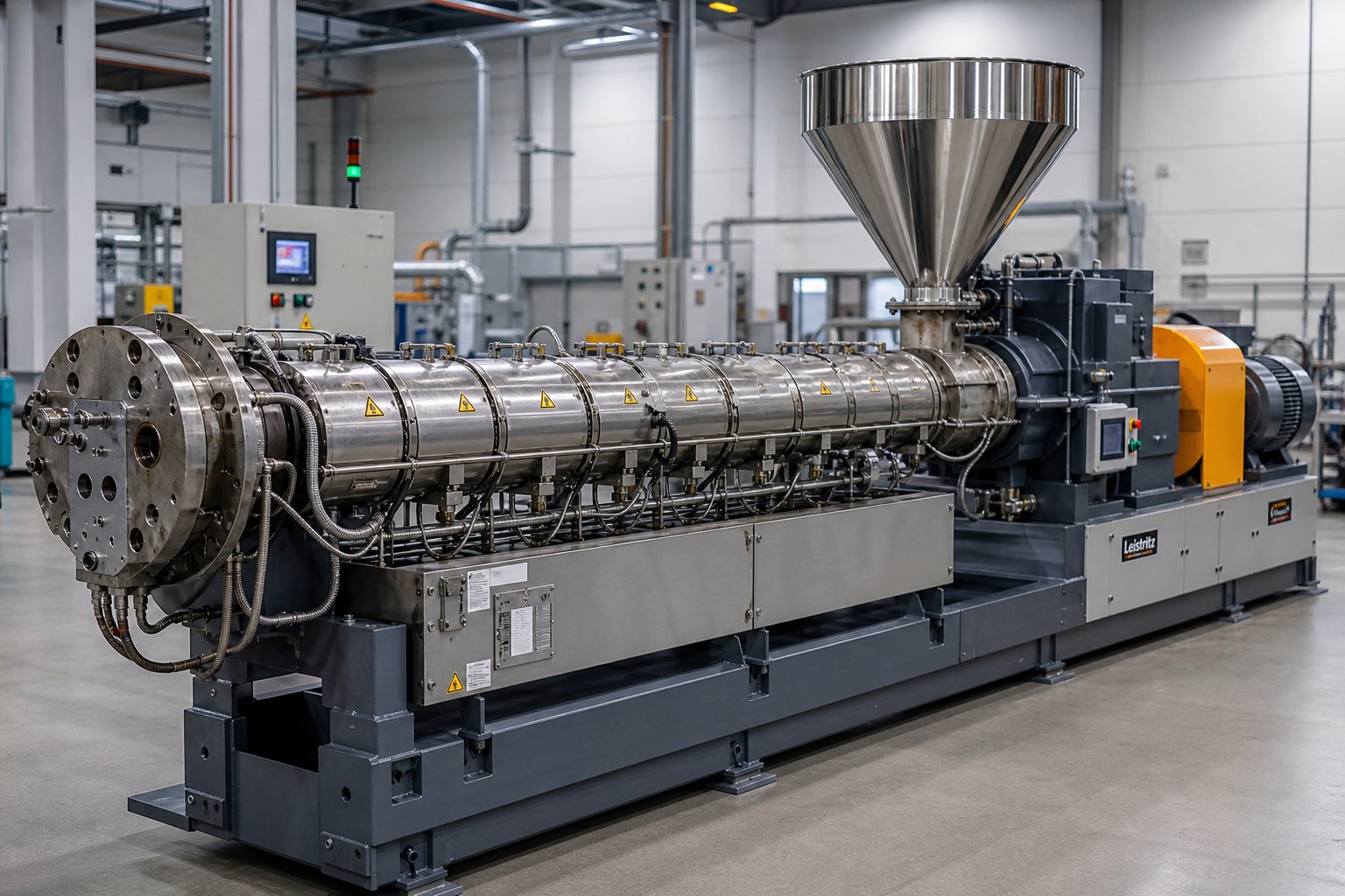
What a Twin Screw Extruder Is and Why It Matters
Imagine two helical screws rotating side by side inside a heated steel barrel, grabbing raw plastic pellets at one end and pushing out a fully melted, perfectly blended material at the other. That, in its simplest form, is how a twin screw extruder works. It is the machine responsible for nearly every compounded polymer you encounter daily — from the PVC in your window frames to the color masterbatch in a shampoo bottle cap.
A twin screw extruder is a processing machine that uses two intermeshing screws, rotating inside a temperature-controlled barrel, to convey, melt, mix, and pressurize plastic or other materials before shaping them through a die.
Unlike a surface-level overview or a product catalog, this article follows the material itself — from the moment it drops into the hopper to the instant it exits the die. Every mechanical principle, every temperature zone, and every screw element you'll read about ties back to that journey. The goal is to give you a clear, mechanism-focused understanding of twin screw extrusion that you can actually use on the shop floor or in an engineering review.
Defining the Twin Screw Extruder in Plain Terms
A twin screw extruder belongs to a broader family of screw-based processing machines, but its twin screw design sets it apart in one critical way: the two screws intermesh. That interlocking geometry creates a self-wiping action — the flight of one screw continuously sweeps material off the surface of the other — which prevents stagnation, ensures uniform heat exposure, and delivers mixing intensity that a single-screw machine simply cannot match. The result is a highly controllable process capable of handling everything from standard thermoplastics to abrasive mineral-filled compounds and moisture-laden recycled flake.
Who Needs to Understand Twin Screw Extrusion and Why
The audience for this knowledge is broader than you might expect. Production operators benefit from understanding why a specific screw element sits where it does — it turns troubleshooting from guesswork into logic. Process engineers evaluating co-rotating versus counter-rotating configurations need the mechanical reasoning behind each design to make defensible decisions. Procurement teams comparing extruder types or screw barrel suppliers gain negotiating power when they understand how component choices affect output quality and throughput.
Whether your processing line produces pipe, profile, sheet, pellets, or recycled compounds, the underlying working principle is the same. The differences lie in screw arrangement, barrel configuration, and process parameters — all topics we'll unpack in detail. First, though, you need to know what's under the hood: the core components that make the entire twin screw extrusion process possible.
Core Components That Power the Twin Screw Extrusion Process
Every twin screw extruder machine, regardless of manufacturer or application, is built around five interdependent subsystems. Remove any one of them and the process stops. Understand all five and you'll be able to read the machine like a blueprint — seeing exactly where energy enters, where material transforms, and where quality is won or lost.
The table below maps each subsystem to its function and its direct impact on what comes out of the die.
| Component | Function | Impact on Processing |
|---|---|---|
| Drive System (Motor + Gearbox) | Delivers torque and rotational speed to both screw shafts | Determines maximum throughput, filler loading capacity, and energy input to the melt |
| Segmented Barrel | Provides a sealed, temperature-controlled chamber around the screws | Governs melting behavior, melt viscosity, and thermal history of the material |
| Modular Screw Elements | Convey, melt, mix, and pressurize material along the shafts | Defines shear intensity, residence time distribution, and mixing quality |
| Feed System (Hopper + Side Feeders) | Introduces raw materials at controlled rates into the barrel | Controls barrel fill level, formulation accuracy, and process stability |
| Die Head | Shapes the pressurized melt into the final product geometry | Influences product dimensions, surface finish, and back-pressure on the screw |
Drive System and Torque Delivery
Picture the drive system as the heart of the twin-screw extruder machine. A variable-frequency AC motor — or, increasingly, a permanent magnet synchronous motor — generates rotational power. That power flows into a high-torque distribution gearbox, which performs two critical jobs simultaneously: it reduces motor speed to the operating RPM range of the screws, and it splits the torque equally between the two parallel shafts.
Why does this matter on the production floor? Because torque, not motor horsepower alone, sets the ceiling for what the machine can do. Engineers evaluate this through a parameter called specific torque — the torque available per unit of screw center-distance volume. A higher specific torque allows higher throughput, greater filler loading, and lower specific energy consumption. If your gearbox cannot deliver enough torque, increasing screw speed or feed rate will simply trigger an overload alarm, and your throughput hits a wall.
Barrel and Screw Assembly Overview
Here is a detail that surprises many newcomers: the twin screw barrel is not a single machined tube. It is a series of modular barrel sections — typically eight to twelve segments — bolted together end to end. Each section features its own electric heaters wrapped around the outside and internal water-cooling channels, creating an independently controlled temperature zone. This segmented design lets engineers set a precise thermal profile along the full length of the barrel, ramping heat up where melting is needed and pulling it back where shear-generated heat threatens to degrade the polymer.
The modularity extends to function as well. Certain barrel segments include open ports for feeding, side-stuffing of fillers, or venting of volatiles. Swapping a closed barrel section for a vented one — or repositioning a side-feeder port — can be done without replacing the entire barrel assembly. The twin screw and barrel, in other words, form a configurable processing platform rather than a fixed machine.
Inside this barrel, the screw elements slide onto splined shafts and lock into place in any sequence the process engineer specifies. Conveying flights, kneading discs, and mixing elements can be arranged and rearranged to match different polymers, fillers, and end-product requirements. This modular screw architecture is so central to how the machine works that it deserves its own deep dive — but first, it helps to trace the path that raw material actually follows as it travels from hopper to die.
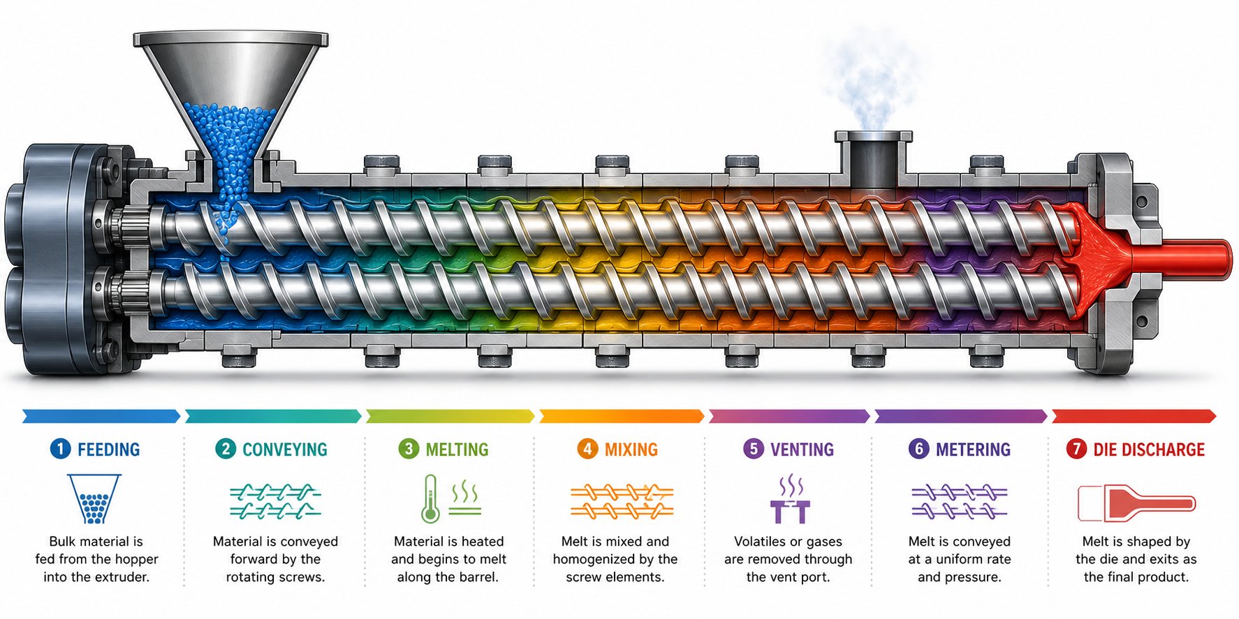
Step-by-Step Material Journey From Hopper to Die
Imagine a real-world scenario: you are compounding polypropylene with 40% calcium carbonate filler to produce pellets for injection molding. The raw polymer pellets enter at one end, powdered mineral enters partway down the barrel through a side feeder, and uniform, bubble-free compound pellets exit at the other end. What happens between those two points is the twin screw extrusion process in action — a sequence of seven distinct stages, each controlled by screw geometry, barrel temperature, and machine parameters working together.
- Feeding — Polymer pellets drop from the hopper into the first open barrel section, where forward-pitched conveying elements pick them up. Most co-rotating systems operate in starve-fed mode: external gravimetric feeders meter material into the barrel at a controlled rate rather than letting the twin screws pull in as much as they can grab. This decouples feed rate from screw speed, giving operators independent control over throughput and shear.
- Solid Conveying — The screw flights push the solid pellets forward. The driving force is a friction differential: the barrel wall grips the material more strongly than the screw surface does, so drag from the barrel converts screw rotation into forward motion. Fill level in this zone stays relatively low under starve-fed conditions, which prevents premature compaction and erratic pressure spikes.
- Melting — As the material advances, it encounters higher barrel temperatures and, more importantly, kneading block elements. Melting results from a combination of conducted heat from the barrel wall and intense viscous dissipation — the mechanical energy generated when the twin screws shear the softening pellets against each other and the barrel. In our calcium carbonate example, the polymer must reach a fully molten state before the mineral filler is introduced downstream.
- Mixing — Once the melt is established, the screw extruder transitions into distributive and dispersive mixing zones. Distributive mixing spreads the filler particles uniformly throughout the polymer matrix. Dispersive mixing applies enough stress to break apart filler agglomerates and wet each particle with molten resin. Kneading elements staggered at 30 degrees, 60 degrees, or 90 degrees control how aggressively the material is sheared — wider stagger angles mean higher dispersive intensity.
- Devolatilization — Moisture carried in by the calcium carbonate, trapped air, and any low-molecular-weight volatiles must be removed before the compound reaches the die. Dedicated vent ports — atmospheric or connected to a vacuum pump — handle this task.
- Metering — The final conveying section stabilizes forward flow and builds the pressure needed to push the melt through the die. Consistent pressure here translates directly to consistent pellet weight and shape downstream.
- Die Discharge — The pressurized melt exits through a strand die or an underwater pelletizing die head, where it is cut into pellets, cooled, and collected.
From Hopper to Melt — Feeding, Conveying, and Melting
The first three stages determine whether everything downstream succeeds or struggles. A poorly fed screw extruder produces surging output. Inconsistent melting leaves solid fragments that choke kneading elements and cause pressure instability. That is why experienced engineers treat the feeding and melting zones as the foundation of every screw extrusion recipe: get the melt right early, and mixing and venting become far more predictable.
In the polypropylene-plus-filler scenario, the base polymer enters the main hopper while the calcium carbonate powder is introduced several barrel sections later through a side stuffer — after the polymer has already melted. This staged feeding strategy prevents the abrasive powder from grinding against unmelted pellets and protects the conveying elements from excessive wear.
Mixing, Degassing, and Die Discharge Explained
The mixing section is where the twin screws earn their reputation. Material traveling in the channel of one screw reaches the intermeshing zone and transfers into the channel of the opposite screw, creating a figure-eight flow path that folds and reorients the melt repeatedly. This cross-channel transfer is what makes distributive mixing in a twin screw extruder so much more effective than the single helical channel of a conventional machine.
Venting, meanwhile, relies on a clever mechanical trick. Immediately upstream of each vent port, reverse-pitch elements or tightly staggered kneading blocks create a melt seal — a fully filled, high-pressure zone that prevents molten polymer from traveling backward toward the vent. Downstream of that seal, the screw profile switches to wide-pitch conveying elements that deliberately leave the barrel only partially filled. This low-pressure, partially filled zone directly beneath the vent opening allows moisture, air, and volatiles to escape upward through the port without melt leaking out. Research on devolatilization in co-rotating twin-screw extruders confirms that increasing screw speed reduces the degree of fill in the vent zone, which enlarges the exposed melt surface area and improves volatile removal efficiency.
By the time the material reaches the metering section, it has been melted, mixed, de-gassed, and homogenized — all within a single continuous pass through the barrel. The final screw flights compress the melt into a stable, pressurized stream that feeds the die evenly. Any fluctuation in this pressure shows up immediately as dimensional variation in the pellet, sheet, or profile coming off the line.
Each of these seven stages depends on which screw elements sit in which barrel position — and that raises a natural question: what determines whether a particular zone conveys gently, shears aggressively, or seals tightly? The answer lies in the difference between co-rotating and counter-rotating screw configurations and the forces each geometry creates.
Co-Rotating vs Counter-Rotating Twin Screw Configurations
Two screws sit inside every twin screw extruder — that much is clear from everything covered so far. But the direction those screws rotate relative to each other changes the physics of the entire process. A co rotating twin screw extruder and a counter-rotating twin screw extruder are not simply two versions of the same machine running backward and forward. They create fundamentally different flow fields, apply different stress types to the material, and serve different applications as a result. Understanding the mechanics of each configuration is essential to grasping how twin screw extrusion really works.
How Co-Rotating Screws Create the Figure-Eight Flow Path
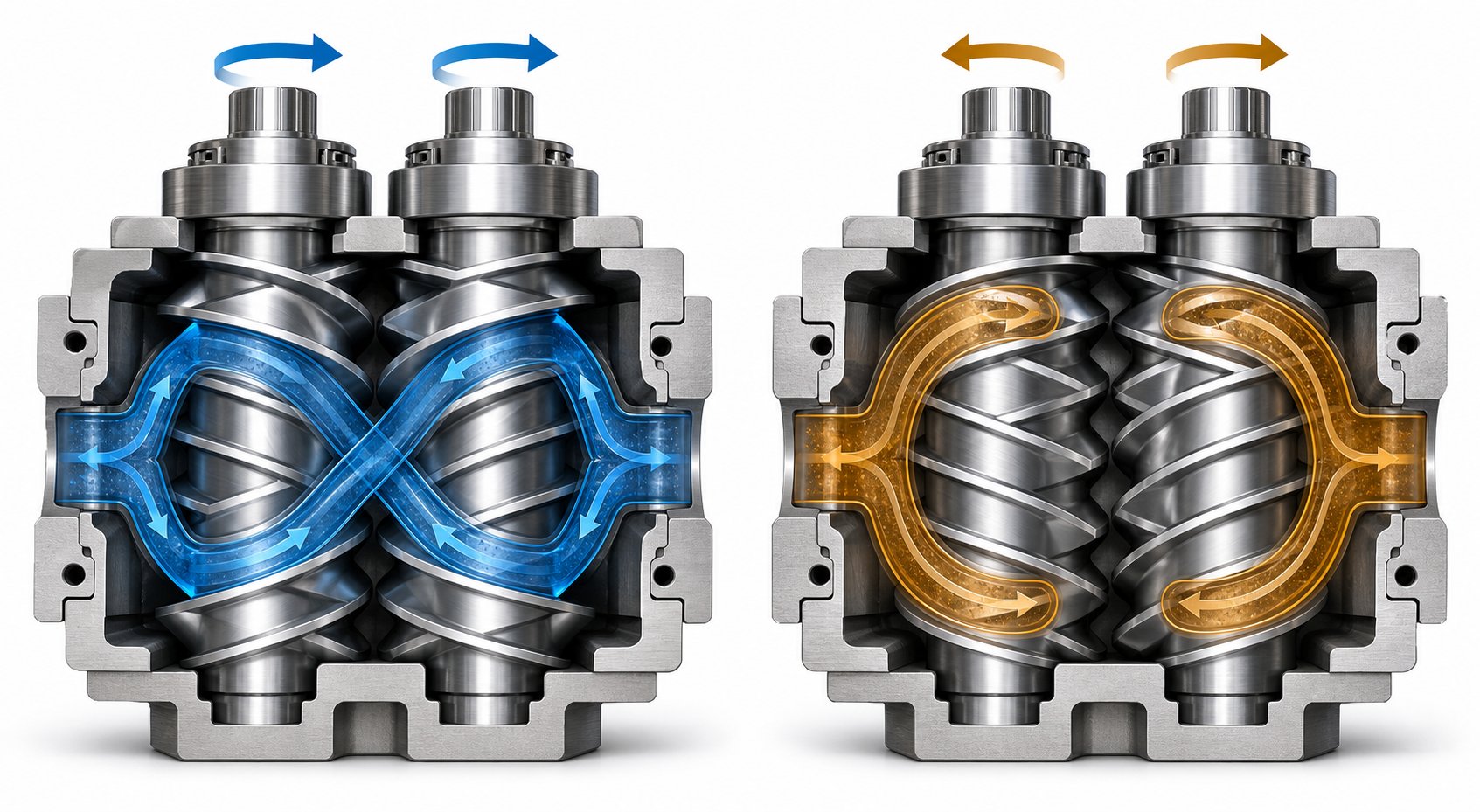
In a co rotating twin screw extruder, both screws turn in the same direction — either both clockwise or both counterclockwise. Fully intermeshing geometry is the standard here, meaning the flight of one screw reaches deep into the channel of the opposite screw. Imagine material traveling forward in the helical channel of the left screw. When it reaches the intermeshing zone — the narrow gap where the two screw profiles overlap — it cannot simply continue along that same channel. Because both screws rotate the same way, the flight of the right screw sweeps the material out of the left screw's channel and redirects it into the right screw's channel. The material then travels along the right screw until it reaches the next intermeshing point, where the transfer reverses.
Trace this path from above and you'll see it forms a figure-eight, or infinity-shaped, loop. Each pass through the intermeshing zone reorients the material, stretches it, and folds it back on itself. This repeated cross-channel transfer is the mechanism behind the intense distributive mixing that makes co-rotating designs the default choice for polymer compounding, masterbatch production, and reactive extrusion.
The intermeshing geometry also produces a second, equally important phenomenon: self-wiping. The flight tip of one screw continuously sweeps along the root diameter of the other screw, scraping material off surfaces before it can stagnate. As extrusion specialists at Technovel explain, this self-wiping action suppresses stagnation and adhesion, keeping the residence time distribution narrow. Why does that matter in practice? Because a narrow residence time distribution means every particle of material spends roughly the same amount of time inside the barrel. Heat-sensitive polymers, reactive formulations, and compounds prone to thermal degradation benefit enormously — there are no pockets of material sitting idle long enough to overheat or cross-link prematurely.
You'll also notice that the self-wiping mechanism eliminates dead zones inside the barrel. This gives process engineers reliable control over the degree of fill, simplifies color changes and material transitions, and reduces scrap during product changeovers. For operations running multiple formulations on the same extruder, that operational flexibility translates directly into saved time and raw material.
Counter-Rotating Screws and the Calendering Effect
Counter-rotating twin screw extruders flip the script. Here, one screw turns clockwise while the other turns counterclockwise. At the intermeshing region, the two screw flights move toward each other rather than in the same direction, drawing material inward and compressing it between the screws. Instead of the open figure-eight transfer seen in co-rotating designs, the counter-rotating geometry creates closed, C-shaped chambers — pockets of material effectively trapped between successive flights and the barrel wall.
These closed chambers behave like a positive-displacement pump: material advances forward one chamber at a time, driven directly by screw rotation. This makes conveyance highly predictable and stable, even at low rotational speeds and high fill levels. More importantly, the intermeshing region between the counter-rotating screws produces a calendering effect. Picture two calender rolls pressing a sheet of rubber — the material passes through a narrow nip, experiencing compressive and elongational deformation rather than the high-speed shear typical of co-rotating machines. The result is effective dispersive mixing under relatively gentle conditions, with significantly lower shear-induced heat generation.
This characteristic is exactly why the counter-rotating configuration dominates rigid PVC processing. PVC has a notoriously low thermal decomposition temperature and poor melt flow. Subject it to the intense shear of a co-rotating twin screw extruder, and you risk degradation, discoloration, and release of hydrochloric acid. The counter-rotating design, by contrast, allows extrusion at lower temperatures through a combination of high-fill, low-speed operation and the gentle calendering action at the screw intermesh. It is the reason counter-rotating extruders remain the standard for PVC pipe, sheet, and profile extrusion lines worldwide.
Within the counter-rotating category, two distinct geometric layouts exist: parallel and conical.
- Parallel twin screw extruder — Both screws maintain a uniform diameter from feed end to discharge. This geometry offers consistent shear distribution along the full barrel length and is well suited for continuous production of profiles, pipes, and products demanding dimensional stability over extended runs.
- Conical twin screw extruder — The screws taper from a larger diameter at the feed end to a smaller diameter at the discharge. This natural compression ratio enhances melting and pressure generation without requiring as many specialized screw elements. The wider feed section accommodates bulky, low-bulk-density materials — a common scenario in PVC dry-blend processing — while the narrower discharge section builds the high pressures needed for die forming. Because the larger end also provides greater shaft separation, a conical screw extruder can house a more robust gearbox, delivering higher torque transmission in a compact footprint. This makes conical designs particularly popular in medium-capacity PVC extrusion lines where floor space and capital efficiency both matter.
The table below consolidates the mechanical and performance differences between co-rotating and counter-rotating configurations across the dimensions that matter most when selecting or evaluating a twin screw extruder.
| Dimension | Co-Rotating Twin Screw Extruder | Counter-Rotating Twin Screw Extruder |
|---|---|---|
| Rotation Direction | Both screws rotate in the same direction | Screws rotate in opposite directions |
| Flow Pattern | Figure-eight (infinity-shaped) cross-channel transfer | Closed C-shaped chambers with positive displacement |
| Shear Intensity | High — intense shear fields between screws and barrel | Lower — compressive and elongational deformation dominate |
| Mixing Type | Strong distributive and dispersive mixing via kneading elements | Calendering-based dispersive mixing under gentle conditions |
| Self-Wiping Capability | Fully self-wiping; minimal dead zones | Limited or no self-wiping; material can stagnate in closed chambers |
| Pressure Generation | Moderate — pressure built primarily in metering section | High — positive displacement provides inherent pressure buildup |
| Screw Geometry Options | Parallel (standard) | Parallel or conical |
| Primary Applications | Polymer compounding, masterbatch, reactive extrusion, nanocomposites | PVC pipe, profile, sheet extrusion; heat-sensitive materials |
Choosing between a co rotating and counter rotating twin screw extruder is not a matter of which is "better" — it is a matter of matching the flow field to the material. A polypropylene compound loaded with glass fiber demands the aggressive distributive mixing of a co-rotating design. A rigid PVC window profile requires the low-shear, high-pressure stability of a counter-rotating machine. Both configurations share the same fundamental advantage over single-screw designs: the intermeshing geometry that makes twin screw extrusion so versatile in the first place.
Yet configuration alone does not fully explain how engineers tailor the process to each formulation. The real precision tool is something both co-rotating and counter-rotating platforms share — a modular screw design system that lets you rebuild the processing profile element by element without changing the barrel or the drive.
How Modular Screw Design Creates Custom Processing Profiles
Think of a twin-screw extruder's shaft as a blank sentence waiting for words. The screw elements are those words — each one performing a specific grammatical function — and the order you place them in determines whether the sentence makes sense or falls apart. This modular architecture is the single feature that separates twin screw extruders from virtually every other polymer processing machine. The barrel stays the same. The motor stays the same. But swap ten elements on each shaft and you have an entirely different process.
As researchers at NC State Extension point out, configuring a screw profile is a blend of art and science because every material exhibits unique flow properties under varying temperature, shear rate, and extruder geometry conditions. No universal template exists. Instead, engineers select from three primary families of screw elements, each with a distinct processing function, and arrange them along the shaft to match the material and the target product.
Types of Screw Elements and Their Processing Functions
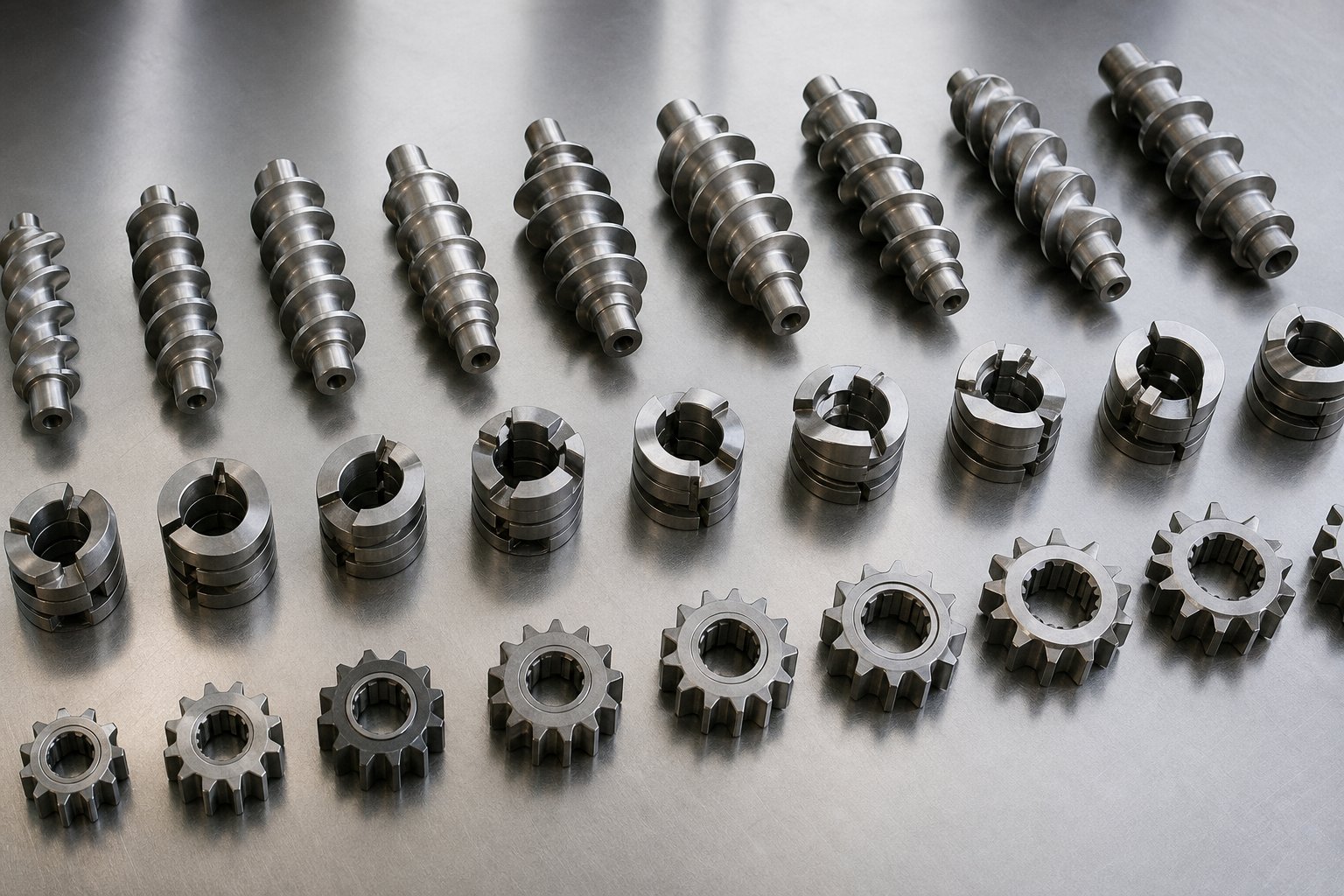
Every element you'll find on a twin-screw extruder shaft belongs to one of these families:
- Conveying elements — These look like traditional helical flights and serve as the workhorses of material transport. Their job is to move material forward without applying aggressive shear. Pitch — the axial distance between consecutive flights — is the primary design variable. A larger pitch increases theoretical conveying capacity and moves material quickly, while a smaller pitch reduces conveying speed but increases compression and pressure generation. Process engineers use wide-pitch conveying elements under the feed port where rapid intake matters, then transition to tighter-pitch elements near the die where stable pressure buildup is critical. By varying pitch along the shaft, you control fill level and residence time in every zone of the barrel.
- Kneading elements — These are disc-shaped blocks stacked on the shaft, each disc offset from its neighbor by a defined stagger angle. The stagger angle is the single most influential variable in determining mixing behavior. At 30 degrees, the discs maintain a forward-pumping action with moderate shear — ideal for distributive mixing where you want to spread additives evenly without hammering the material. At 60 degrees, shear intensity increases significantly, and the element begins to resist forward flow, generating the kind of stress peaks needed for dispersive mixing and agglomerate breakup. At 90 degrees — so-called neutral kneading blocks — the element has virtually zero net conveying capacity. Material oscillates back and forth across the discs, experiencing maximum residence time and the most intense mixing. Reverse-staggered kneading blocks push material backward against the forward flow, creating powerful melt seals and extreme shear. As detailed in NC State's screw functionality guide, forward kneading elements are less aggressive, neutral elements increase residence time because they only impart energy without conveying, and reverse kneading blocks create maximum restriction and maximum shear. Disc width matters too — narrower discs produce more frequent flow disruptions and higher local pressure fluctuations, boosting dispersive action, while wider discs favor gentler distributive blending.
- Mixing and special elements — This family includes two critical subtypes. Reverse-pitch conveying elements are standard helical flights wound in the opposite direction, pushing material backward to create a restriction point. They increase upstream pressure, extend residence time in the preceding zone, and form the melt seals essential for effective devolatilization. Toothed mixing elements (sometimes called ZME or gear-mixing elements) feature rows of interlocking teeth rather than continuous flights. They repeatedly split and recombine the melt stream without generating the high shear stress of kneading blocks, making them excellent tools for distributive blending when you need uniform composition without excessive heat input. These elements are especially valuable in fiber-reinforced compounds where preserving fiber length is critical.
How Engineers Build a Screw Profile for Compounding
Imagine you're setting up a twin-screw extruder to compound a glass-fiber-reinforced nylon. How would you arrange these elements? The logic follows the material journey described earlier, and it plays out in a specific sequence along the shaft:
Under the main feed port, you place wide-pitch conveying elements to rapidly accept pellets from the hopper and move them forward without compression. A few barrel sections downstream, as barrel temperatures climb, you transition to a kneading block section — typically a combination of forward-staggered and neutral kneading discs — that melts the polymer through combined barrel heat and viscous dissipation. Immediately after the melting zone, you return to conveying elements that pull the melt forward and reduce pressure, creating a partially filled region beneath the vent port where moisture and trapped air escape.
Past the vent, a side-feeder port introduces chopped glass fibers into the already-molten polymer. Here, you deliberately choose distributive mixing elements — low-stagger kneading blocks or toothed mixing elements — that blend fibers into the matrix without breaking them into useless fragments. An aggressive dispersive mixing section here would destroy the very reinforcement you're trying to incorporate. Finally, a section of tight-pitch conveying elements compresses the melt, builds stable pressure, and meters the material evenly into the die.
The beauty of this system is its reversibility. Tomorrow, if that same extruder needs to produce a highly filled calcium carbonate masterbatch instead of glass-fiber nylon, the process engineer pulls the screw shafts, slides off the elements, and reassembles an entirely different profile — perhaps with more aggressive kneading blocks for filler deagglomeration and an additional reverse element to extend mixing residence time. The barrel segments, the gearbox, and the motor remain untouched. This reconfigurability is why twin-screw extruders dominate compounding facilities that run dozens of different formulations on a single production line.
Screw element selection, however, is only half the equation. Each of those barrel sections housing the screw profile has its own temperature setpoint, and the interplay between screw geometry and barrel temperature is what ultimately determines melt quality, mixing intensity, and product consistency. That relationship — along with the process parameters that tie everything together — is where operational control truly lives.
Barrel Temperature Zones and Key Process Parameters
Screw elements define what happens to the material mechanically, but thermal control decides whether that mechanical action produces a high-quality melt or a degraded mess. Every barrel section along the length of a plastic twin screw extruder carries its own heating and cooling hardware, and every knob on the control panel — screw speed, feed rate, torque limit — interacts with that thermal profile in ways that directly shape product quality. Ignore these relationships and even a perfectly designed screw profile will underperform.
Independent Barrel Zone Heating and Cooling
Recall that the barrel is not a single piece of steel — it is a chain of modular sections bolted together. Each section wraps around the twin screws with its own set of electric cartridge heaters (or, in some designs, oil-circulation heating jackets) and internal water-cooling channels. This gives every section the ability to add or remove heat independently, creating what operators call a temperature profile — a deliberate zone-by-zone thermal map that governs how the material behaves at each stage of its journey.
A typical production-scale extruder might feature 8 to 12 independently controlled zones from the feed throat to the die. On a laboratory twin screw extruder or a benchtop twin screw extruder used for formulation development, the number may be smaller — perhaps four to six — but the principle is identical. Each zone has a dedicated PID temperature controller that continuously compares the measured barrel wall temperature against a setpoint and adjusts heater output or cooling-water flow to maintain it.
In practice, the temperature profile generally follows a recognizable pattern. The feed zone stays relatively cool — often well below the polymer's softening point — to prevent premature melting that could block material intake. As extrusion training specialists note, typical feed-zone temperatures for standard thermoplastics range from 20 degrees C to 60 degrees C, though higher values are sometimes set deliberately to reduce drive torque at very high throughputs. Temperatures then ramp upward through the melting and mixing zones — typically climbing above the polymer's crystalline melting point or glass transition temperature — where conducted heat from the barrel wall works alongside viscous dissipation from the kneading elements to complete the phase transition. Toward the final metering section and die, the profile stabilizes or may even decrease slightly to manage melt viscosity and minimize thermal degradation before the material exits.
One critical subtlety: the setpoint temperature displayed on the controller rarely equals the actual melt temperature inside the barrel. Viscous dissipation from screw rotation generates internal heat that the barrel thermocouple, mounted in the steel wall, does not fully capture. Experienced operators learn to read motor load, melt-pressure trends, and downstream melt-temperature probes alongside zone readouts to build an accurate picture of what the material actually experiences. Adjusting a single zone's setpoint can take many minutes to produce a visible effect on product quality, and neighboring zones influence each other through heat conduction along the barrel body — which is why temperature optimization in extrusion remains both time-intensive and skill-dependent.
Screw Speed, Feed Rate, and Torque — The Control Triangle
Beyond barrel temperatures, three process parameters form the operational backbone of every twin screw extrusion run. They interact so tightly that changing one always affects the other two — think of them as a triangle where pulling one corner stretches the other two.
| Parameter | What It Controls | Effect of Increasing It |
|---|---|---|
| Screw Speed (RPM) | Shear rate applied to the material and residence time in the barrel | Higher shear intensity, shorter residence time, greater viscous heat generation, lower degree of screw fill at constant feed rate |
| Feed Rate (kg/hr) | Barrel fill level and overall throughput | Higher output, increased degree of screw fill, tighter residence time distribution, higher torque demand on the drive |
| Torque (% of maximum) | Mechanical energy transmitted from the motor through the screws into the material | Indicates greater resistance to screw rotation — typically caused by higher fill, higher viscosity, or more restrictive screw elements |
Screw speed is the operator's primary lever for controlling shear. Increase RPM and the material experiences more frequent passes through high-shear zones — the screw-to-barrel overflight gap, the intermesh region, and the kneading block faces. This boosts mixing intensity but also shortens the time each particle spends inside the barrel, which can be beneficial for heat-sensitive formulations or problematic if the material needs extended dwell time to fully homogenize. Because twin screw extruders are starve-fed, screw speed does not determine throughput — that role belongs to the feeders.
Feed rate is set by the gravimetric or volumetric feeders upstream of the barrel. Raising the feed rate increases the degree of screw fill — the percentage of available free volume in the screw channels actually occupied by material. Higher fill levels tighten the residence time distribution, meaning every particle travels through the barrel in closer to the same amount of time. However, more material in the screws demands more torque from the drive. Push the feed rate too high relative to the screw speed, and the torque climbs toward the machine's safety limit.
Torque is not a setpoint you dial in — it is a response. It reflects how hard the motor is working to turn the screws against the resistance created by the material's viscosity, the screw element geometry, and the degree of fill. Monitoring torque as a percentage of the machine's maximum allowable value is standard practice on every production line. A sudden spike signals a change — perhaps a batch of resin with higher molecular weight, a clogged screen pack, or a feed upset. A gradual climb over weeks can indicate barrel or screw wear reducing clearances.
The parameter that ties all three together is specific energy (SE) — the amount of motor power input per kilogram of material processed, expressed in kilowatt-hours per kilogram. As detailed in industry analysis from PlasticsToday, specific energy is calculated by multiplying the motor's kilowatt rating by the percentage of torque used and the ratio of running RPM to maximum RPM (adjusted for gearbox efficiency), then dividing by the throughput in kilograms per hour. SE is the single number that most directly correlates with mixing intensity and melt quality. If a formulation consistently runs at an SE of 0.25 kW per kg/hr and the value suddenly shifts to 0.16, something has changed — feedstock properties, element wear, or barrel temperature drift — even if every setpoint on the control screen looks normal.
Tracking specific energy across batches, across machine sizes, and even across plant locations gives engineers a universal benchmark for process consistency. It is especially valuable during scale-up: a recipe developed on a small laboratory twin screw extruder can be transferred to a production-scale machine by targeting the same SE value, adjusting screw speed and feed rate to match. This principle holds whether you are scaling from a benchtop twin screw extruder processing grams per minute to a 75-mm production line running at hundreds of kilograms per hour.
Temperature profiles, screw speed, feed rate, and torque — these are the levers that transform a mechanical assembly of screws and barrels into a controllable process. Yet none of these parameters would matter nearly as much if the twin screw design did not already possess an inherent mixing advantage over simpler machines. That advantage — rooted in the intermeshing geometry, self-wiping action, and starve-fed operation covered in earlier sections — is precisely what elevates twin screw extruders above their single-screw counterparts in every mixing-intensive application.
Why Twin Screw Extruders Outperform Single Screw Designs
Every mechanism explored so far — the figure-eight flow path, the self-wiping intermesh, the modular screw profile, and the independently zoned barrel — points to the same conclusion: twin screw extruders are fundamentally different machines from their single-screw counterparts, not just upgraded versions. The differences are not cosmetic or incremental. They originate in the physics of how material moves through each design, and they dictate which machine belongs on which production line.
Mixing and Self-Wiping Advantages Rooted in Twin Screw Geometry
In a single screw extruder, the polymer occupies one continuous helical channel. The barrel wall acts as the stationary surface and the rotating screw creates drag flow — material near the barrel surface moves fastest, while material near the screw root barely moves at all. This velocity gradient produces shear, but it also creates stratification. Material tends to stay in roughly the same radial position as it travels downstream, with limited turnover across the channel cross-section. As extrusion expert Jim Frankland explains, this stratification makes it inherently difficult to completely mix the contents of the single-screw channel because the polymer strongly adheres to both the barrel and screw surfaces after melting, and shear thinning further reduces the velocity near the screw root.
A double screw extruder sidesteps this limitation entirely. The intermeshing zone between the two screws forces a complete channel-to-channel transfer of material — not just the top layer, but the entire cross-section. Frankland emphasizes that the twin can transfer the entire channel full of polymer from one screw to the other multiple times, permitting full-channel mixing while imparting high shear to only a small portion of the melt at each transfer point. This selective shear application is critical: it allows intensive dispersive mixing — breaking filler agglomerates, delaminating clay platelets, distributing pigment particles — without overheating the bulk of the polymer.
Single screw extruders attempt to overcome their mixing limitation by inserting barrier flights, Maddock mixers, or pin-type mixing sections into the screw. These devices do offer some interruption and redirection of the melt stream. However, each one creates flow resistance, reducing output and elevating melt temperature. Because there is no second screw to transfer material into, every gram of polymer must pass through the restriction, and any mixing improvement comes at a direct throughput penalty. Repeating these restrictions along the screw compounds the output loss, which is why multi-stage intensive mixing on a single screw remains impractical for most compounding applications.
The self-wiping action of a double screw extruder machine adds another dimension that single screw designs simply cannot replicate. Flight tips on one screw continuously scrape the root of the other, preventing material from stagnating on metal surfaces. This keeps the residence time distribution tight and minimizes the risk of thermal degradation — a critical advantage when processing heat-sensitive polymers like PVC, EVOH, or bioplastics. Single screw extruders have no equivalent mechanism; material can linger in low-velocity zones near the screw root for extended periods, accumulating heat and potentially degrading before it reaches the die.
Then there is the matter of independent control. Because twin screw extruders operate in starve-fed mode — with external feeders metering material into the barrel — feed rate and screw speed are decoupled. An operator can hold throughput constant and raise RPM to increase shear, or reduce RPM to limit shear without losing output. A single screw extruder, by contrast, is flood-fed: it pulls in as much material as its channel can grab. Screw speed and throughput are locked together. Increase RPM and output rises in tandem, giving the operator no independent lever for adjusting shear intensity. This coupling is one of the most overlooked reasons why screw extruders designed with twin screw geometry dominate mixing-intensive applications.
When a Single Screw Extruder Is Still the Right Choice
Editorial honesty matters here. Single screw extruders are not obsolete — far from it. For applications where the material is already fully compounded and the machine's job is simply to melt and pump that material through a die, a single screw machine is often the smarter investment. Film extrusion, basic pipe production, and sheet lines running pre-compounded resins are prime examples. In these scenarios, intensive mixing is unnecessary, energy consumption per kilogram is typically lower, capital cost is substantially reduced, and the mechanical simplicity of a single screw translates into easier maintenance and shorter downtime.
The decision between a single and double screw extruder machine should always start with the process requirement, not with the machine specification. If you need to blend, react, devolatilize, or disperse — choose twin. If you need to melt and meter a uniform feedstock into a forming die — a single screw may serve you equally well at lower cost.
The key working-principle differences between the two designs can be distilled into five dimensions:
- Mixing mechanism — Twin screws transfer material between channels for full cross-sectional turnover; a single screw relies on drag flow within one channel, producing stratified velocity and limited radial mixing.
- Feeding mode — Twin screw extruders use starve feeding, decoupling screw speed from throughput and enabling independent shear control; single screw machines are flood-fed, locking output to RPM.
- Modular flexibility — Twin screw shafts accept interchangeable conveying, kneading, and mixing elements that can be rearranged for each formulation; a single screw is typically a one-piece design optimized for a specific material and output range.
- Residence time control — Self-wiping intermesh and adjustable fill levels give twin screws a narrow, controllable residence time distribution; single screw designs exhibit broader residence time spread due to velocity stratification and dead zones.
- Processing versatility — Twin screw extruders handle compounding, reactive extrusion, devolatilization, and recycling on one platform; single screw machines excel at steady-state melting and pumping of pre-formulated materials.
This comparison is not a scorecard — it is a decision framework grounded in the mechanical realities each design creates. Understanding why the twin screw mechanism outperforms for mixing-intensive tasks is what equips engineers and procurement teams to place the right machine in the right application. And the applications themselves — compounding, recycling, pelletizing, and more — each demand specific screw configurations and barrel setups that translate these working principles into finished products.
Real-World Applications Across Plastics Processing Lines
Every working principle covered so far — modular screw profiles, independent barrel zone control, starve-fed operation, and the figure-eight mixing path — exists for one reason: to solve specific processing problems in real production environments. A compounding twin screw extruder running glass-fiber nylon and a recycling line reprocessing post-consumer HDPE flake may share the same drive system and barrel architecture, but their screw configurations, temperature profiles, and downstream equipment look entirely different. The application defines the machine's personality.
Polymer Compounding and Masterbatch Production
Polymer compounding is where the twin screw compounding extruder earns its reputation as an industry workhorse. Imagine producing a 30% glass-fiber-reinforced polyamide for automotive under-hood components. The base resin must be fully melted before fragile glass fibers are introduced downstream through a side stuffer — otherwise, grinding abrasion against unmelted pellets would shatter the fibers into useless dust. The screw profile in the melting zone features aggressive kneading blocks, while the fiber incorporation zone switches to gentle distributive mixing elements that wet the fibers without breaking them. Independent barrel temperatures in the mixing zone stay high enough to keep nylon viscosity low, reducing fiber attrition further.
Color masterbatch production presents the opposite challenge. Here, pigment agglomerates — sometimes only a few microns across — must be broken apart and dispersed so uniformly that the final injection-molded part shows zero streaking or specking. Dispersive mixing intensity matters more than gentle handling, so the screw profile loads up on tightly staggered 60-degree and 90-degree kneading blocks that generate the shear stress peaks needed to rupture agglomerate bonds. A twin screw plastic extruder running masterbatch may operate at higher RPM and lower throughput compared to the same machine running filled engineering resin, because the priority shifts from output volume to dispersion quality.
Engineering plastics — polycarbonate blends, PBT compounds, TPE formulations — all rely on the same fundamental capability: the ability to independently control shear intensity, residence time, and thermal history at each point along the barrel. No other continuous processing technology offers this level of precision, which is why the co-rotating compounding extruder has been the standard in compounding facilities for over half a century.
Recycling, Pelletizing, and Specialty Applications
Recycling lines expose one of the twin screw extruder's most critical capabilities: devolatilization. Post-consumer plastic waste — washed HDPE flake, regrind PP containers, or shredded PET packaging — enters the barrel carrying residual moisture, trapped air, printing ink residues, and low-molecular-weight volatiles. If these contaminants remain in the melt, they cause bubbles, voids, discoloration, and odor in the finished pellet. Multi-stage venting, often with vacuum assist, strips these volatiles from the melt in the partially filled, low-pressure zones created by the screw profile beneath each vent port.
As Charlie Martin of Leistritz details, co-rotating twin screw extruders excel at removing residual moisture left over from the washing step in PCR processing — a task that is often problematic from a processing perspective when handled by other equipment. The TSE also disperses trace minor-phase polymers inherent in a mixed post-consumer feed stream and can incorporate fillers at levels up to 80% to improve the mechanical properties of recycled compounds. However, Martin cautions that the tight geometric tolerances between intermeshing screws make TSEs vulnerable to damage from metal contaminants or foreign objects in poorly sorted feedstock, so robust upstream metal detection and filtration design are essential.
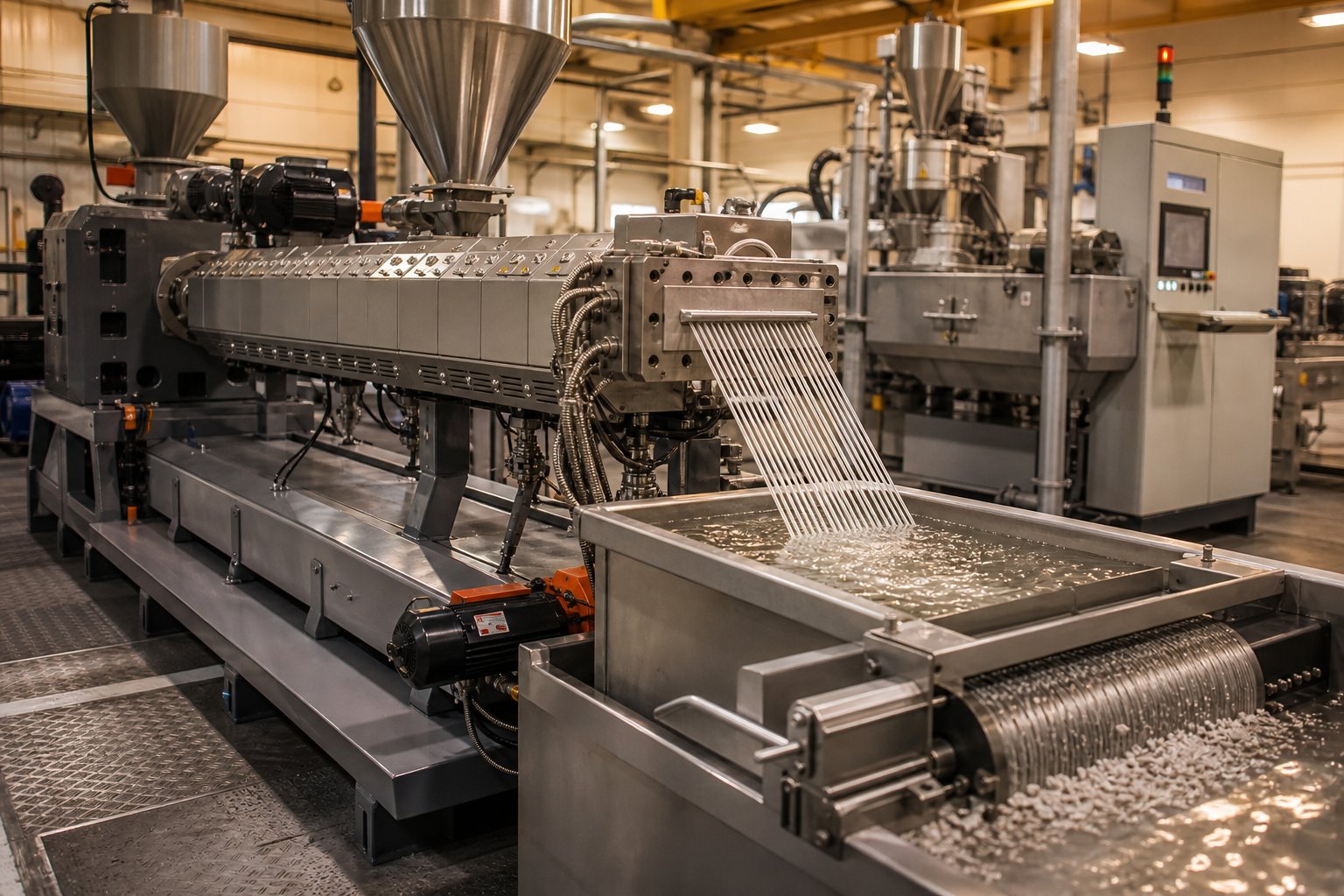
A screw extruder granulator — a twin screw extruder paired with a strand pelletizer or underwater pelletizing system — is the backbone of most recycling and compounding lines. The extruder homogenizes and de-gasses the melt, a gear pump stabilizes pressure, and the pelletizer cuts the extrudate into uniform granules ready for downstream molding or extrusion. Pipe and profile lines, by contrast, replace the pelletizer with a calibration die, vacuum sizing tank, and haul-off system. Sheet lines use a flat die feeding a polishing roll stack. In every case, the upstream twin screw extrusion process remains fundamentally the same — only the die geometry and downstream equipment change.
The table below connects each major application to the screw configuration and process parameters that matter most, translating working-principle knowledge into actionable production context.
| Application | Key Screw Configuration | Critical Process Parameters |
|---|---|---|
| Filled polymer compounding (CaCO3, talc) | Aggressive kneading blocks for filler deagglomeration; side stuffer for downstream filler feeding; reverse elements for melt seals before vents | High specific torque to handle filler loading; moderate RPM to balance dispersion vs. heat buildup; SE typically 0.15 - 0.25 kWh/kg |
| Glass-fiber-reinforced compounds | Distributive mixing elements (low-stagger kneading, toothed elements) after fiber side-feed; avoid high-shear zones post-fiber introduction | Lower RPM to preserve fiber length; barrel temps kept above polymer Tm to reduce melt viscosity and fiber breakage |
| Color masterbatch | Multiple high-intensity kneading sections (60 - 90 degree stagger); extended mixing zone length | Higher RPM for maximum dispersive shear; lower feed rate to increase residence time and pigment dispersion quality |
| Post-consumer recycling (HDPE, PP, PET) | Multi-stage vent sections with vacuum; extended L/D ratio; coarse filtration downstream | Vacuum level at vent ports critical for volatile removal; feed rate adjusted to moisture content; metal detection mandatory upstream |
| PVC pipe and profile extrusion | Counter-rotating screws (parallel or conical); gentle compression zones; no high-shear kneading blocks | Low RPM and low barrel temps to prevent thermal degradation; high die pressure for dimensional accuracy |
| Pelletizing (compounding output) | Metering section with tight-pitch conveying for stable pressure; gear pump between extruder and strand die | Consistent melt pressure at die face governs pellet weight uniformity; water temperature in pelletizer controls pellet shape |
One pattern emerges clearly from this table: matching the correct screw and barrel configuration to each application is every bit as important as the extruder platform itself. The same 75-mm co-rotating machine can produce flawless color masterbatch or disastrous glass-fiber compound depending entirely on which elements sit on the shafts and how the barrel zones are programmed. For extrusion manufacturers, recycling plants, and technical teams looking to specify or upgrade screw and barrel setups for pipe, profile, sheet, pelletizing, or recycling lines, NANHAIYA's plastic extruder machine and screw barrel support offers application-specific configurations that align screw geometry with material properties and processing goals — a practical resource for teams ready to move from understanding how the machine works to optimizing what it produces.
With applications spanning everything from automotive-grade engineering plastics to post-consumer waste reprocessing, the twin screw extruder's versatility is undeniable. Yet versatility without a clear mental model of the underlying mechanism is just complexity. What ties every application, every screw profile, and every barrel zone together into a single coherent picture — and how that picture guides real-world configuration decisions — is the final piece worth assembling.
Bringing It All Together and Choosing the Right Configuration
You have followed the material from hopper to die, watched it melt under the combined forces of barrel heat and viscous dissipation, tracked it through the figure-eight mixing path between intermeshing screws, and seen volatiles escape through cleverly engineered low-pressure vent zones. Each mechanism — drive torque, modular screw elements, segmented barrel zones, and starve-fed operation — plays a defined role. Strip any one away and the process falls apart. Keep them all in balance and you have the most versatile continuous processing platform in polymer manufacturing.
The Working Principle in One Paragraph
A twin screw extruder works by transmitting motor torque through a distribution gearbox to two intermeshing, modular screws rotating inside a segmented, independently heated and cooled barrel. Raw material enters through a starve-fed hopper, is conveyed forward by helical flight elements, melted through a combination of conducted barrel heat and mechanical shear from kneading blocks, mixed distributively and dispersively as it transfers between screw channels in a figure-eight flow path, degassed through atmospheric or vacuum vent ports positioned over partially filled low-pressure zones, metered to stable pressure by tight-pitch conveying elements, and finally shaped through a die into pellets, pipe, profile, sheet, or film.
That single description captures the complete mechanism. Every design decision a twin screw extruder manufacturer makes — screw diameter, L/D ratio, kneading block stagger angle, barrel zone count, gearbox torque rating — traces back to optimizing one or more stages within this sequence for a specific material and application.
Choosing the Right Screw and Barrel Configuration
Understanding how the machine works is the foundation. But here is the reality that separates a functioning extruder from an optimized one: two identical twin screw extruder plastic platforms, running the same resin at the same throughput, can produce dramatically different results depending on which screw elements sit on the shafts and how the barrel zones are programmed. A screw profile designed for aggressive pigment dispersion will destroy glass fibers. A gentle distributive mixing configuration will leave calcium carbonate agglomerates intact. The mechanism is universal — the configuration is specific.
Operators and procurement teams evaluating new equipment or upgrading existing lines should approach screw and barrel selection with the same rigor they apply to resin qualification. Key questions to ask include: Does the screw geometry match the shear sensitivity of the target polymer? Are there enough independent barrel zones to create the thermal profile the formulation demands? Is the gearbox torque rating sufficient for the highest filler loading the line will encounter? Can the screw profile be reconfigured for future products without replacing the barrel?
These are not questions you answer alone. Experienced screw barrel suppliers who understand the relationship between element geometry, material rheology, and process outcomes are essential partners — not just parts vendors. For extrusion manufacturers, recycling plants, and technical teams working across pipe, profile, sheet, pelletizing, and general plastic processing lines, NANHAIYA's plastic extruder machine and screw barrel support provides application-specific configurations designed to match screw and barrel specifications to real processing requirements. It is a practical next step for anyone ready to move from understanding twin screw working principles to specifying or upgrading their own equipment.
Before you finalize any configuration decision, keep these key takeaways in mind:
- The mechanism is a sequence, not a single event — feeding, conveying, melting, mixing, devolatilization, metering, and die discharge are distinct stages, each requiring its own screw element and barrel temperature strategy.
- Co-rotating and counter-rotating are not interchangeable — co-rotating designs deliver superior distributive mixing and self-wiping for compounding; counter-rotating designs provide low-shear, high-pressure stability for heat-sensitive materials like PVC.
- Modular screw design is the twin screw extruder's greatest asset — the same barrel and drive can be reconfigured with entirely different screw profiles for different products, making it the most flexible platform in polymer processing.
- Process parameters form a triangle — screw speed, feed rate, and torque interact constantly; specific energy (kWh/kg) is the single metric that best predicts mixing quality and enables reliable scale-up.
- Screw and barrel selection matters as much as the extruder itself — matching element geometry, metallurgy, and barrel zone configuration to the target material and application is what transforms a general-purpose machine into a high-performance production line.
Whether you are a production operator troubleshooting a pressure spike, a process engineer designing a screw profile for a new formulation, or a procurement specialist comparing twin screw extruder manufacturers for your next capital investment — the working principles outlined in this article give you the mechanical reasoning to make better decisions. The material's journey through the barrel never changes. Your ability to control that journey, element by element and zone by zone, is what defines the outcome.
Frequently Asked Questions About Twin Screw Extruders
1. What is the difference between co-rotating and counter-rotating twin screw extruders?
Co-rotating twin screw extruders have both screws turning in the same direction, creating a figure-eight flow path that delivers intense distributive mixing and a self-wiping action ideal for polymer compounding and masterbatch production. Counter-rotating extruders spin screws in opposite directions, forming closed C-shaped chambers that produce a calendering effect with lower shear and higher pressure buildup. This gentler action makes counter-rotating designs the standard for heat-sensitive materials like rigid PVC in pipe and profile extrusion. The choice depends on whether your application prioritizes aggressive mixing or low-shear pressure stability.
2. Why is a twin screw extruder better than a single screw extruder for compounding?
Twin screw extruders transfer material between two intermeshing screw channels, achieving full cross-sectional turnover that a single helical channel cannot replicate. This intermeshing geometry enables both dispersive mixing — breaking apart filler agglomerates — and distributive mixing — spreading additives uniformly throughout the melt. Additionally, twin screw systems use starve feeding, which decouples screw speed from throughput and gives operators independent control over shear intensity. Single screw machines are flood-fed, locking output directly to RPM. For any application requiring blending, reactive processing, or devolatilization, the twin screw mechanism delivers superior results.
3. What are the main screw elements used in a twin screw extruder?
Three primary families of screw elements are used: conveying elements with helical flights that transport material forward at varying speeds depending on pitch; kneading elements made of staggered discs (at 30, 60, or 90 degrees) that control shear intensity and mixing type; and special elements such as reverse-pitch flights for creating melt seals and toothed mixing elements for gentle distributive blending. Engineers arrange these elements along the shaft in a custom sequence tailored to the target material and product. Suppliers like NANHAIYA (nhyscrews.com) offer application-specific screw and barrel configurations for pipe, profile, sheet, pelletizing, and recycling processing lines.
4. What is specific energy in twin screw extrusion and why does it matter?
Specific energy (SE) measures the motor power input per kilogram of material processed, expressed in kilowatt-hours per kilogram. It is calculated by multiplying the motor's kilowatt rating by the torque percentage and RPM ratio, then dividing by throughput. SE is the single parameter that most directly correlates with mixing intensity and melt quality. It serves as a universal benchmark for process consistency across batches and machine sizes, making it invaluable during scale-up from laboratory extruders to production-scale equipment. A sudden shift in SE — even when all setpoints appear normal — signals changes in feedstock properties, element wear, or thermal drift.
5. What applications are twin screw extruders used for?
Twin screw extruders serve a wide range of plastics processing applications. Polymer compounding uses aggressive kneading profiles to disperse fillers like calcium carbonate, glass fiber, and pigments into base resins. Post-consumer recycling relies on multi-stage devolatilization to strip moisture and volatiles from washed plastic flake. Masterbatch production demands high-shear screw configurations for pigment dispersion. PVC pipe and profile lines use counter-rotating designs for gentle, low-temperature processing. Pelletizing lines pair the extruder with strand or underwater cutting systems. Each application requires a tailored screw and barrel configuration matched to the material's rheology and thermal sensitivity.
Written by
Nanhaiya Technical Team
Zhoushan Nanhaiya Plastic Machinery Co., Ltd.
The Nanhaiya technical team supports screw and barrel manufacturing projects through application review, technical communication, custom manufacturing coordination, and production and quality control.
Discuss Your Application
Related Articles
More insights on screw barrel technology and plastics processing.

What Nobody Tells You About Screw Barrel For Plastic Machine Design
Oct 10, 2026
Learn how screw barrel for plastic machine design affects melt quality, throughput, and wear life. Covers geometry, resin matching, troubleshooting, and sourcing.
Read Article
Single Screw Extruder for Sheet: Stop Guessing, Start Specifying
Oct 9, 2026
Learn how to specify a single screw extruder for sheet production. Covers screw geometry, resin-specific processing, troubleshooting, and maintenance best practices.
Read Article
PE Pipe Extruder Machine: What Datasheets Won't Tell You
Oct 9, 2026
Learn how a PE pipe extruder machine works, key specs explained, material grade selection, maintenance tips, and buyer guidance beyond the datasheet.
Read ArticleLooking for something else?
Search by material, symptom or product and jump straight to the relevant page.
These are navigation suggestions based on keyword matching — not a quotation, not a delivery commitment, and not a substitute for engineering review. Final specification is confirmed by our engineers against your drawings and processed material.
Need help with screw barrel selection?
Share your machine model, processed material and application. Our team can help with pricing and technical support.