

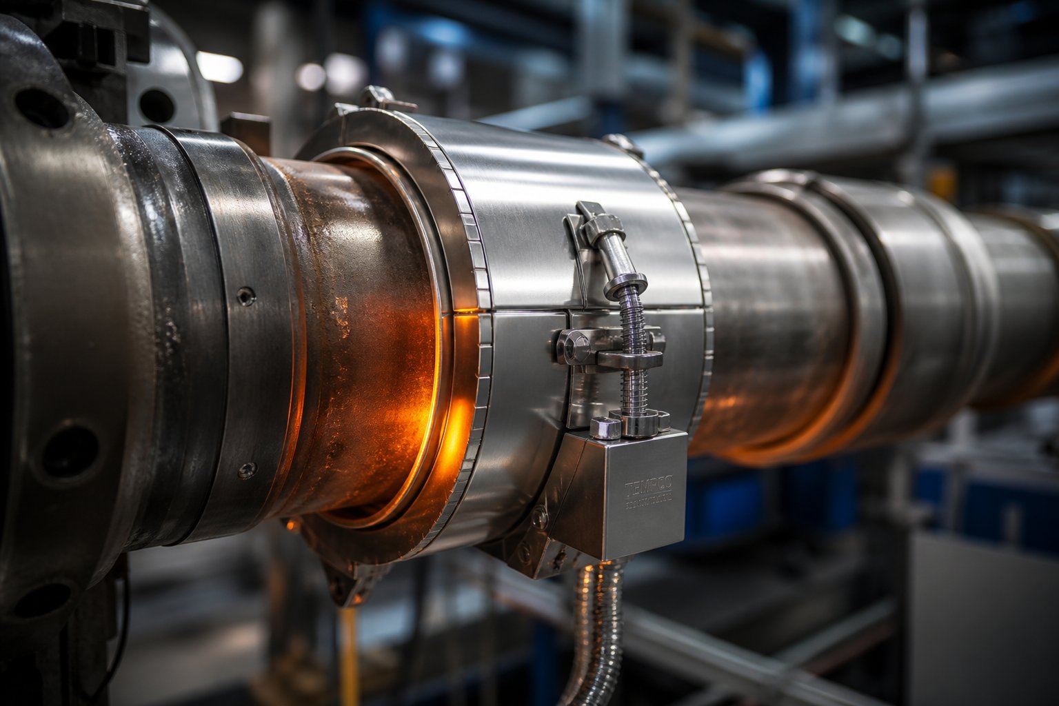
What Is a Heater Band and How Does It Work
A heater band is a cylindrical electric heating element that clamps around barrels, pipes, nozzles, and drums to deliver precise, uniform radial heat. Inside its ring-shaped body, an electrically resistive element — typically nichrome wire or etched foil — converts electrical energy into thermal energy through Joule heating. That heat passes through an insulating layer and transfers directly into the workpiece by conduction, raising its temperature in a controlled, repeatable way.
Unlike cartridge heaters that slide into drilled holes or strip heaters that bolt against flat surfaces, a band heater wraps the outside of a cylinder. This external-contact approach means you can remove and replace the heating band in the field without disassembling machinery — a major advantage when uptime matters.
How a Heater Band Generates and Transfers Heat
Think of the construction as three concentric layers working together. The innermost layer is the resistance element — nichrome wire wound in a precise pattern or an etched-foil circuit. Surrounding that element sits an insulating medium (mica sheets, interlocking ceramic tiles, or compacted magnesium oxide) that electrically isolates the element while still conducting heat inward. The outermost layer is a metal sheath, usually stainless steel, that provides structural rigidity and protects internal components from contamination.
Clamping force is the critical link in this chain. When heater bands are tightened firmly against a barrel surface, the sheath makes full circumferential contact, allowing efficient thermal transfer across the entire heated zone. Poor contact — caused by a dirty surface, loose hardware, or a mismatched diameter — creates air gaps that act as insulation in the wrong place. The result is localized overheating and premature element burnout, the single most common failure mode in the field.
Where Heater Bands Fit in the Industrial Heating Landscape
Compared to cartridge heaters, cast-in heaters, and induction heating systems, band heaters stand out for their ease of removal, straightforward replacement, and field serviceability. You don't need to pull a barrel apart or call in specialized technicians — a maintenance tech with basic tools can swap a unit during a scheduled stop.
Key advantages that make this style of heating so widely adopted include:
- Uniform circumferential heating around the entire barrel surface
- Tool-free or minimal-tool installation using built-in clamp mechanisms
- Wide temperature range from moderate process heat up to extreme industrial demands
- Multiple insulation options (mica, ceramic, mineral) to match specific operating envelopes
- Availability in custom diameters, widths, and wattages for virtually any cylindrical geometry
These characteristics explain why the band heater remains the dominant external heating solution across plastics processing, chemical manufacturing, packaging, and food production — industries where reliable temperature control directly impacts product quality and throughput.
The real performance differences, however, emerge when you look at insulation type. Mica, ceramic, and mineral-insulated constructions each unlock different temperature ceilings, watt densities, and service-life expectations — factors that determine whether your heater bands last months or years under demanding production schedules.
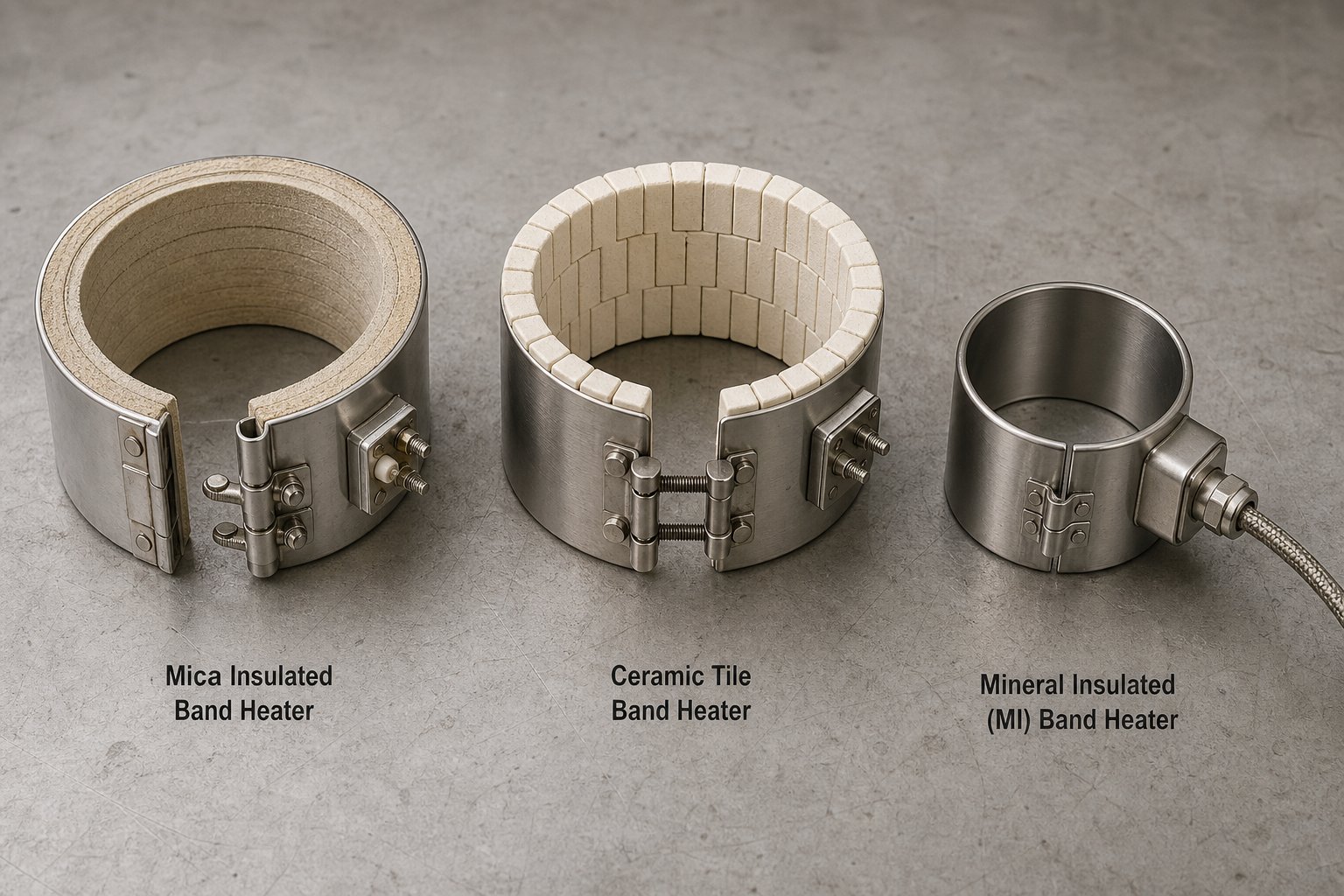
Mica vs Ceramic vs Mineral-Insulated Heater Bands Compared
Choosing an insulation type is the single most consequential decision you'll make when specifying a heater band. The insulating medium controls everything downstream — maximum operating temperature, watt density capability, energy efficiency, response time, and ultimately, how long the unit lasts under your specific process conditions. Three primary insulation families dominate the market: mica, ceramic, and mineral-insulated. Each one serves a distinct operating envelope, and selecting the wrong type is a fast track to premature burnout and costly downtime.
Mica Band Heaters and Their Operating Envelope
The mica band heater is the workhorse of the plastics industry — and for good reason. Its construction is straightforward: a precision-wound nickel-chromium resistance ribbon sits between stacked mica sheets, all enclosed in a corrosion-resistant steel sheath. Industry data from SFP places the continuous sheath temperature rating at approximately 600°F, with short-term tolerance up to 900°F. Typical watt densities top out around 35 W/in² for diameters between six and ten inches.
Why is mica so popular? It delivers good thermal conductivity, strong dielectric strength, resistance to moisture and chemicals, and it's flexible enough to conform to curved barrel surfaces. Mica band heaters are also economical, easily customized, and quick to manufacture — making them ideal for general-purpose injection molding, extrusion barrels, and packaging equipment. Their limitation is straightforward: when your process demands temperatures above 900°F, standard mica insulation simply can't keep up.
That said, HT mica bands push the boundary. These high-temperature, high-density variants use upgraded mica formulations to extend the operating ceiling to approximately 1,200°F, bridging the gap between standard mica and the heavier ceramic or mineral-insulated designs.
Ceramic Band Heaters for High-Temperature Demands
When process temperatures climb beyond what mica can handle, ceramic band heaters step in. Instead of layered mica sheets, interlocking ceramic tiles serve as the insulating medium between the resistance element and the outer sheath. This construction supports continuous operating temperatures reaching approximately 1,200°F to 1,400°F and higher watt densities than mica counterparts.
Imagine a high temperature band heater that insulates itself. That's the ceramic advantage — the tiles naturally resist outward heat loss, directing more thermal energy inward toward the barrel. The result is lower energy consumption at the barrel surface and reduced ambient heat in the work area. However, because ceramic tends to retain heat, temperature controllability can be slightly less responsive than mica. Controllers may need tighter PID tuning to prevent overshoot. Ceramic band heaters cost more upfront, but in demanding applications, the longer service life and energy savings often justify the investment.
Mineral-Insulated and Specialty Heater Bands
For the most extreme environments — high vibration, severe contamination, or the tightest possible cross-sections — mineral-insulated (MI) bands deliver. These units pack compacted magnesium oxide (MgO) around the resistance element inside a seamless metal sheath. The result is excellent thermal conductivity, strong corrosion resistance, and continuous temperature capability up to roughly 1,400°F. MI bands tend to be more expensive than mica, but their rugged, sealed construction provides longer service life in applications where standard insulation would degrade quickly.
Beyond these three primary types, specialty configurations address niche requirements. Rectangular band heaters accommodate non-cylindrical geometries such as square or rectangular manifolds and die bodies. A silicone band heater, on the other hand, uses a flexible silicone rubber construction for lower-temperature applications — typically below 400°F — where conformability and moisture resistance matter more than high heat output. Think drum warming, laboratory vessels, and food-processing equipment.
| Insulation Type | Max Continuous Temp | Typical Watt Density | Response Time | Relative Cost | Best Applications |
|---|---|---|---|---|---|
| Mica | ~600°F (900°F short-term) | Up to 35 W/in² | Fast | Low | General-purpose injection molding, extrusion, packaging |
| HT Mica (High-Density) | ~1,200°F | Up to 45 W/in² | Fast | Low–Medium | Higher-temperature molding and extrusion zones |
| Ceramic | ~1,200–1,400°F | Up to 60+ W/in² | Moderate (retains heat) | High | High-temp extrusion, die casting, engineering resins |
| Mineral-Insulated (MI) | ~1,400°F | Up to 60+ W/in² | Moderate | Medium–High | Harsh environments, high vibration, contamination-prone zones |
This comparison highlights a pattern: as temperature and watt density demands increase, so do cost and design complexity. The practical takeaway? Match the insulation type to your actual process requirements — not your worst-case fantasy scenario. Over-specifying drives up cost without delivering proportional benefits, while under-specifying guarantees frequent replacements and unplanned shutdowns.
Of course, choosing the right insulation type is only half the equation. The watt density you specify within that insulation type determines whether your heater band runs comfortably within its limits or constantly operates on the edge of burnout — a balance that deserves its own careful look.
Understanding Watt Density and Heater Band Sizing
Watt density is arguably the most misunderstood specification in industrial heating — and the one most likely to destroy your equipment when it's wrong. In simple terms, watt density measures how much electrical power is concentrated across each square inch (or square centimeter) of heated surface area. It's calculated by dividing the total wattage of the band heater element by its effective heated area. A 1,000-watt unit spread over a large barrel barely warms the surface, while the same 1,000 watts squeezed onto a small nozzle can melt the resistance wire within seconds.
This single metric determines three things simultaneously: how fast your barrel reaches process temperature, how evenly heat distributes around the circumference, and how long the unit survives before it burns out. Get watt density right, and your heating bands deliver years of reliable service. Get it wrong, and you're ordering replacements every few weeks.
Why Watt Density Matters for Performance and Longevity
Here's the fundamental trade-off every engineer and maintenance tech needs to understand. Higher watt density pushes more thermal energy into the barrel per unit area, which means faster heat-up times and the ability to maintain setpoint under heavy production loads. But that intensity comes at a cost — the resistance element runs hotter internally, and if even a small section of the heater loses contact with the barrel, that trapped heat has nowhere to go. The element temperature spikes past its design limit, oxidizes rapidly, and snaps. Total failure.
Lower watt density, on the other hand, keeps the element comfortable and extends service life dramatically. Industry engineering data suggests that reducing watt density by just 10% can roughly double the operational lifespan of a thermal band. The downside? A unit specified too conservatively may not deliver enough power to reach process temperature within acceptable timeframes — especially on large-diameter barrels or in cold ambient environments.
Several factors influence where the sweet spot falls for your specific application:
- Barrel material and wall thickness — Steel conducts heat at roughly 45 W/m·K, meaning thicker walls absorb more energy before the process side reaches setpoint. Barrel alloy composition matters too.
- Ambient conditions — A barrel exposed to cold drafts or outdoor temperatures loses heat faster, demanding higher watt density to compensate.
- External insulation — Adding insulation blankets over heating bands can cut ambient heat loss by up to 40%, effectively allowing you to use a lower, safer watt density while still meeting temperature targets.
- Insulation type — Each material has a hard ceiling. Mica tops out at roughly 3 W/cm² (about 20 W/in²), while ceramic can safely sustain up to 6 W/cm² (approximately 39 W/in²). Exceeding these limits guarantees premature failure regardless of installation quality.
The general approach to calculating required wattage follows a logical sequence: identify the target temperature rise from ambient to process setpoint, determine the mass and specific heat of the barrel section being heated, estimate heat losses to the surrounding environment, and then divide the total required power by the available heated surface area. For material-specific thermal properties — specific heat values, emissivity coefficients, and conduction rates — always reference manufacturer datasheets or engineering handbooks like Marks' Standard Handbook for Mechanical Engineers rather than relying on rules of thumb.
Selecting the Right Size and Configuration
Proper sizing goes beyond watt density alone. A heater band that doesn't physically fit the barrel — even by a millimeter or two — creates the air gaps that trigger the burnout cycle described above. Here's the practical workflow for specifying a correctly sized unit from scratch:
- Measure the barrel outside diameter (OD). Use a caliper or pi tape, not the machine's nominal specification. Actual machined diameters can differ from catalog values by 1-3 mm, and that gap is enough to create poor thermal contact.
- Determine the heated zone width. Measure the available axial length between flanges, tie bars, thermowell bosses, or adjacent heaters. Decide whether a single wide band or multiple narrower bands better suits the zone — narrower bands offer finer temperature profiling but add more electrical connections.
- Choose the construction style. One-piece clamp designs work for most standard barrel diameters. Two-piece split designs simplify installation on large barrels or in tight machine geometries where sliding a full ring into position isn't practical.
- Account for obstructions. Thermowells, barrel flanges, and wiring channels all reduce the usable heated area. Map these features before specifying band width to avoid ordering a unit that can't seat flush.
- Calculate target wattage from watt density. Multiply your chosen watt density (within the safe ceiling for your insulation type) by the effective heated area — and remember to subtract the "cold zones." Every band heater element has unheated sections at the clamping gap and terminal connection points. The corrected formula is: Heated Area = [(ID x 3.14 x Width) - (No-Heat Factor x Width)].
- Specify voltage and termination. Match the supply voltage to your machine's electrical system (typically 220-240V single-phase or 380-415V three-phase). Select the termination type — post terminals, flexible leads, plug connectors, or a junction box — based on the machine's wiring layout and access constraints.
One mistake that surfaces repeatedly in the field: engineers try to solve slow heat-up problems by cramming more wattage into the same physical footprint. This pushes watt density past safe limits and guarantees a shorter lifespan. The smarter path is geometric — specify a wider band to increase total heated area, which lets you add wattage while keeping the surface load within safe boundaries. If physical space on the barrel is limited, pairing existing units with insulation blankets achieves a similar result by redirecting wasted ambient energy back into the process.
Sizing and watt density set the technical foundation, but specifications on paper only matter if they align with real-world operating conditions. The demands placed on a heater band vary dramatically depending on whether it's wrapped around an injection molding barrel running ABS at 450°F or a chemical drum maintaining viscosity at 150°F — and those application-specific requirements shape every decision from insulation type to agency certification.
Key Industrial Applications and Their Specific Requirements
A heater band sitting in a warehouse is just a metal ring with wire inside it. The moment it clamps onto a barrel, a nozzle, or a drum, it becomes part of a process — and each process imposes a unique set of demands. Temperature uniformity, response speed, moisture exposure, regulatory compliance, and duty cycle all shift depending on the application. Understanding these differences is what separates a well-specified system from one that fails within weeks.
Heater Bands in Injection Molding and Extrusion
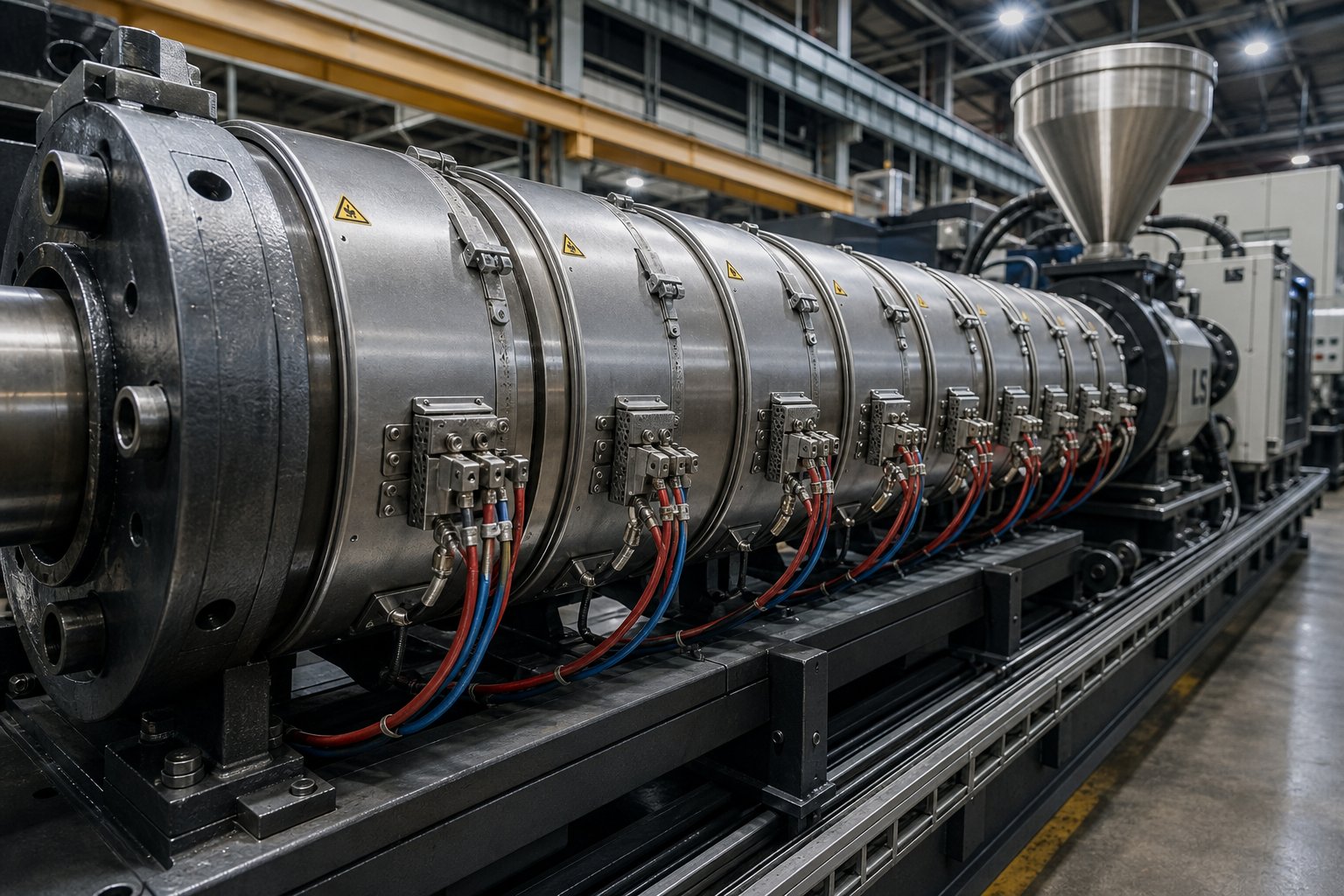
Injection molding barrels and extruder barrels represent the highest-volume application for heater bands worldwide. If you've ever worked around a plastics processing floor, you've seen rows of them — mica or ceramic units clamped along multi-zone barrel assemblies, each zone independently controlled to create a precise thermal profile from feed throat to nozzle tip.
What makes this application so demanding? Consider the specific requirements:
- Tight temperature uniformity across zones. A single barrel may carry four to eight independently heated zones. Each zone must hold its setpoint within a narrow window — often ±2°F — to prevent melt inconsistencies, splay, burn marks, or viscosity swings. As industry analysis from MD Plastics emphasizes, even when every zone reads perfectly on the controller, the actual melt temperature is governed more by shear and screw design than by the heaters alone. That reality makes consistent, reliable heat delivery from each band even more critical — any unit that drifts or fails throws the entire profile off balance.
- Rapid heat-up for production starts. Machines often sit cold overnight or over weekends. When production begins, heater bands for injection molding need to bring barrel temperatures from ambient to processing range — sometimes 400°F to 600°F — within 20 to 40 minutes. This puts a premium on adequate watt density and full barrel-surface contact.
- Durability under continuous operation. Many extrusion lines run 24/7 for weeks at a stretch. Extruder heater bands must tolerate constant thermal cycling as PID controllers pulse power on and off to maintain setpoint. Units with poor insulation or loose clamping degrade rapidly under this relentless duty cycle.
- Thermocouple compatibility. Closed-loop temperature control depends on accurate feedback. Extrusion heater bands must accommodate thermocouple bosses, wiring routing, and sometimes integrated sensor pockets without creating dead spots or gaps in the heated zone.
A specialized sub-type worth calling out is the nozzle band heater. Designed for the smaller diameters and tighter tolerances of injection nozzles and extruder die adapters — typically three inches or less — these compact units deliver high watt density in a narrow footprint. According to IQS Directory, nozzle band heaters can reach a maximum watt density of 40 W/in² with temperature capabilities up to 850°F, using ceramic, mica, or mineral insulation depending on the process. Their small size demands precise manufacturing tolerances; even a slight diameter mismatch creates air gaps that lead to hot spots and drool at the nozzle tip.
Drum Heating, Pipe Tracing, and Specialty Uses
Step away from the plastics floor, and heater bands serve an entirely different category of needs. Drum heater bands wrap around 55-gallon steel or poly drums to maintain bulk materials — resins, adhesives, waxes, oils, and food-grade liquids — at controlled temperatures so they flow properly during dispensing. Imagine trying to pump cold honey out of a barrel. Band heaters for drums solve exactly that problem by keeping viscosity within a pumpable range without overheating the material.
These drum applications typically operate at much lower temperatures than injection molding — often below 300°F — but introduce other challenges. The drum heater band must distribute heat gently and uniformly to prevent localized scorching of heat-sensitive materials. Thermostat or variable-control options allow operators to dial in a precise temperature, and many units include built-in over-temperature protection to prevent charring or degradation of the drum contents.
Pipe-mounted heater bands serve a different purpose altogether: freeze protection and process temperature maintenance. In chemical plants and refineries, band heaters for pipe installations keep process fluids — caustics, polymers, fuel lines — above their pour point or crystallization temperature during cold weather or extended shutdowns. These applications demand moisture-resistant construction, robust grounding, and often hazardous-area certifications because the heaters operate in environments with flammable vapors or corrosive atmospheres.
Beyond these primary markets, heater bands also appear in analytical instrumentation, laboratory autoclaves, die casting equipment, blown film lines, and packaging machinery. Each niche adds its own wrinkle — die casting demands extreme temperature capability, blown film requires tight circumferential uniformity, and packaging equipment values fast cycling and compact profiles.
The key takeaway? Selection criteria change significantly by application. Here are the factors that shift most:
- Temperature range — from gentle drum warming at 150°F to high-performance extrusion at 900°F+
- Watt density — low and gentle for heat-sensitive materials, high for rapid barrel heat-up
- Moisture resistance — critical for outdoor pipe tracing, wash-down food environments, and chemical plants
- Agency certifications — UL, CSA, CE, and FM approvals ensure compliance with electrical safety standards and are often mandatory for OEM equipment or regulated industries
- Material contact ratings — food-grade or pharmaceutical applications require FDA-compliant materials and documented traceability
Selecting a heater band that matches these application-specific demands is essential — but even the best-specified unit operates in a vacuum without proper temperature feedback and power regulation. The real performance gains come when heaters, sensors, and controllers work together as an integrated system, each component reinforcing the others.
How Heater Bands Integrate with Controllers and Thermocouples
A heater band bolted to a barrel without temperature feedback is like driving a car with your eyes closed — you're moving, but you have zero control over where you end up. In practice, no heater band operates in isolation. It functions as one component in a closed-loop heating system where each piece depends on the others: the band generates heat, a thermocouple senses the resulting temperature, a controller compares that reading to the setpoint, and a power output device adjusts energy delivery accordingly. Break any link in that chain, and you get material degradation, scrap, or equipment damage.
Understanding this system-level integration is what separates a well-tuned process from one plagued by temperature swings, burned resin, and premature heater failures.
Thermocouples and Sensor Placement for Accurate Control
The thermocouple is your barrel's voice — it tells the controller what's actually happening at the metal surface. Without that feedback, even a perfectly specified band heater with thermocouple provision becomes uncontrolled, running at full output until something fails or overheats.
Two thermocouple types dominate plastics processing. Type J (Iron-Constantan) remains the industry standard for most injection molding and extrusion applications because it offers high sensitivity in the 200°C to 400°C processing range and resists the reducing atmospheres found inside tight barrel bores. Type K (Chromel-Alumel) takes over when you're running high-performance engineering resins like PEEK or Ultem where melt temperatures exceed 400°C.
Sensor placement matters just as much as sensor type. A spring-loaded bayonet thermocouple embedded in the barrel wall reads the actual steel temperature with minimal lag. A surface-mounted sensor, by contrast, reads the outer barrel skin — which can differ from the bore temperature by 20°F or more depending on wall thickness and heat flow. The critical installation detail? Setting proper spring pre-load. According to industry best practices, compressing the bayonet spring approximately 12-15mm before locking creates constant forward pressure (roughly 2-5 lbs) that eliminates the invisible air gap between the sensor tip and the thermowell bottom. Without that pre-load, the sensor reads low, the controller overdrives the heaters, and carbonization follows.
For maintenance teams sourcing matched components, suppliers like NANHAIYA provide both heater bands and thermocouples as part of a broader extruder spare parts catalog — making it practical to order heating-system components from a single vendor familiar with extrusion and injection molding equipment rather than juggling multiple suppliers for each zone rebuild.
Temperature Controllers and Power Regulation
The controller is the brain of the system. It receives the thermocouple signal, calculates the difference between actual and desired temperature, and commands a power output to close the gap. Three controller types appear across industrial heating applications:
- On/off controllers — the simplest option. They energize the heater at full power when temperature drops below setpoint and cut power entirely when it rises above. Cheap, but they produce constant thermal cycling that stresses band heater elements and shortens service life.
- PID controllers — the standard for precision plastics processing. Proportional-Integral-Derivative logic modulates power output smoothly, reducing overshoot and eliminating the aggressive on/off cycling that degrades heater bands prematurely. A well-tuned PID band heater temperature controller holds setpoint within ±1°F and significantly extends element lifespan by avoiding repeated thermal shock.
- SCR-based (thyristor) power regulators — paired with PID controllers to deliver proportional power rather than simple switching. As technical documentation from Lorentzzi explains, a closed-loop thyristor power regulator provides constant current, constant voltage, or constant power output to the heater, making it far less sensitive to supply voltage fluctuations than open-loop solid-state relays or contactors. The analog output from the PID controller (typically 4-20 mA or 0-10 VDC) linearly controls the regulator's output, effectively reducing electrical shock to the heater and greatly extending its operational life.
Modern controllers add another valuable layer: energy monitoring and predictive maintenance. By logging heater current draw over time, these systems detect the gradual resistance increase that signals element degradation — flagging a failing zone weeks before it actually burns open. This is especially useful in multi-zone setups where a single failed band can go unnoticed until scrap rates spike. Even a compact mica band heater 24v unit on a laboratory extruder benefits from this monitoring approach, since low-voltage systems are just as susceptible to element degradation as their high-power counterparts.
A practical band heater with thermostat configuration — common on drum heaters and simple pipe-tracing systems — uses a mechanical or electronic thermostat in place of a full PID controller. These systems sacrifice precision for simplicity, cycling the heater on and off around a fixed setpoint without proportional modulation. They're adequate for applications where ±10°F accuracy is acceptable, but insufficient for plastics processing where tight control is non-negotiable.
Insulation Blankets and System Efficiency
Here's a detail many plants overlook: you can buy the most expensive heater band on the market, pair it with a perfectly tuned PID controller, and still waste 30-40% of your energy budget radiating heat into the factory air. Insulation blankets — removable, form-fitting jackets that wrap over installed heater bands — capture that wasted radiant and convective energy and redirect it back into the barrel.
The benefits are compounding. Less heat escapes outward, so the controller demands less power to maintain setpoint. Lower duty cycle means reduced thermal cycling on the element. Reduced cycling extends service life. And as a bonus, surface temperatures drop dramatically, reducing burn hazard for nearby workers.
Proper system integration — heater band, thermocouple, controller, and insulation — can reduce energy use by 20-40% while extending heater band service life, delivering savings on both the utility bill and the replacement parts budget simultaneously.
The lesson is clear: a heater band is never just a heater band. It's one node in a thermal system, and optimizing performance means treating it that way — matching sensors, controllers, power regulation, and insulation as a unified package rather than sourcing each piece in isolation.
Even with a perfectly integrated control system, however, the physical installation determines whether theory translates into results. A loose clamp, a contaminated barrel surface, or a miswired connection can undermine the entire system — which is why proper installation technique and electrical safety protocols deserve focused attention.
Installation Best Practices and Safety Essentials
Here's a statistic that should change the way every maintenance team approaches a heater band swap: forensic engineering data from field inspections across hundreds of injection molding and extrusion facilities reveals that up to 70% of premature band heater failures trace back not to manufacturing defects, but to improper mechanical installation. That means the majority of costly burnouts — and the downtime that follows — are entirely preventable with the right technique.
Installation isn't glamorous work. It's tempting to rush through a swap during a scheduled stop, torque one bolt down hard, and move on. But every shortcut introduces the air gaps, contamination layers, and electrical hazards that turn a reliable clamp heater into a scrap-metal ring within days.
Step-by-Step Heater Band Installation
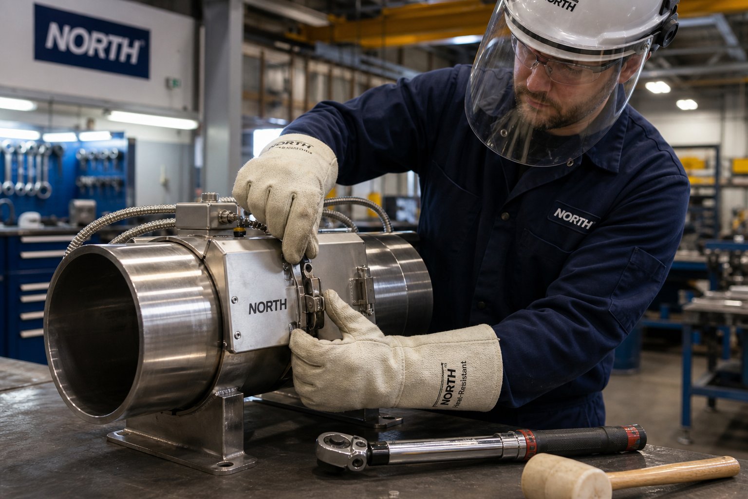
A methodical approach eliminates the guesswork. Follow this sequence every time — whether you're mounting industrial band heaters on a 40mm nozzle or a 300mm extruder barrel:
- De-energize and lock out/tag out (LOTO). Verify the machine is completely powered down and at a safe handling temperature before touching any heating zone. This isn't optional — it's the first line of defense against electrical shock and contact burns.
- Clean the barrel surface thoroughly. Use a brass wire brush or emery cloth to remove all carbonized polymer, oxidation, and factory dust from the mounting zone. Even a 1mm protrusion of hardened plastic acts as a fulcrum that lifts the band away from the barrel, creating the air gap that destroys the element. The surface must be completely flush bare metal — no exceptions.
- Skip the thermal paste. A persistent shop-floor myth suggests applying thermal compound between the band and the barrel, similar to a CPU cooler. Never do this. Standard thermal pastes break down above 100°C, and at the 300°C+ operating temperatures of plastics processing, the liquid carriers boil off while the solids carbonize into a rock-hard insulating crust. The paste literally becomes the air-gap equivalent it was supposed to prevent.
- Position the band and align termination leads. Rotate the unit so electrical terminals or lead wires face away from potential polymer leak zones, moving parts, and downward-facing vents. This prevents mechanical damage and contamination of the connections during operation.
- Tighten clamp hardware using the "tap and tighten" method. Engage the clamping mechanism and hand-tighten until the band grips the barrel but can still be adjusted. Then use a soft rubber or dead-blow mallet — never a steel hammer, which can crush mica insulation or shatter ceramic tiles — to gently tap the outer circumference, seating the band flush against the barrel. Alternate tightening the clamp screws evenly, the same way you'd tighten lug nuts on a wheel. This ensures uniform stress distribution and maximum surface contact.
- Connect wiring per the electrical schematic. For threaded post terminals, always use the "two-wrench method" — hold the bottom nut stationary with one wrench while tightening the top nut with a second. Single-wrench tightening transfers rotational torque through the post directly to the internal resistance wire, snapping it instantly.
- Verify ground continuity before energizing. Confirm that the heater sheath has a solid ground path. Use a multimeter to check continuity between the sheath and the machine's grounding system.
- Perform a hot re-torque. This is the step most technicians skip — and it's the single most impactful action for extending service life. After the controller brings the zone to operating temperature, power down, and immediately retighten all clamp hardware. Thermal expansion loosens the clamping mechanism as the metal grows, and a hot re-torque can extend heater lifespan by over 50% by eliminating the slack that would otherwise create destructive air gaps.
The underlying principle is simple: uneven clamping or a contaminated barrel surface creates air pockets. Air conducts heat roughly 1,700 times worse than carbon steel. Trapped thermal energy backs up into the resistance element, temperatures spike past 800°C internally, and the nichrome wire oxidizes, becomes brittle, and fractures. Every step above exists to prevent that chain reaction.
Electrical Safety and Grounding Requirements
Mechanical installation gets most of the attention, but electrical hazards carry the more serious consequences — arc flash, shock, fire, and catastrophic equipment damage. Proper grounding of the heater sheath provides a low-resistance fault path that trips protective devices before dangerous voltages reach personnel or machine frames.
Ground-fault circuit interrupters (GFCIs) or ground-fault protection relays add a second layer of defense. These devices detect imbalances between line and neutral current — a signature of insulation breakdown or moisture ingress — and disconnect power within milliseconds. For environments where heat bands operate near hydraulic fluids, wash-down spray, or ambient moisture, ground-fault protection is non-negotiable.
Before energizing any newly installed or stored heater band, perform a megger test (insulation resistance measurement). Industry best practice from Watlow calls for testing at 500VDC, with a reading of 500 megohms or higher indicating acceptable insulation integrity. Lower values signal a "wet heater" — one that has absorbed atmospheric moisture into its mineral insulation. Rather than discarding the unit, a bake-out process at 120°C for six hours or more typically restores insulation resistance to safe levels. This is especially important in humid coastal regions or whenever heat bands have been stored for extended periods.
Over-temperature protection strategies add the final safeguard. High-limit controllers — independent from the primary PID controller — monitor zone temperature and cut power if readings exceed a preset ceiling. Thermal fuses embedded in or near the heater provide a last-resort backup, permanently opening the circuit if temperatures reach dangerous levels. Together, these devices prevent runaway heating scenarios that can damage barrels, degrade processed materials, or ignite nearby combustibles.
Thermal Hazard Awareness
Electrical risks are invisible until something goes wrong. Thermal risks, by contrast, are always present during operation — and too often underestimated. Exposed heat bands routinely operate at surface temperatures exceeding 500°F, well above the threshold for severe contact burns. A momentary brush against an unguarded barrel zone can cause third-degree burns before a worker even registers the contact.
Guarding options range from simple sheet-metal shields that deflect accidental contact to full insulation blanket systems that serve double duty. Removable insulation jackets not only protect personnel from burn hazards but also reduce radiant heat loss — cutting energy consumption while keeping the work area cooler and safer. In facilities where multiple workers circulate near barrel zones, OSHA guidelines and common sense both point toward mandatory guarding or insulation on every exposed heating zone.
Never energize a heater band that is not clamped to a barrel or load — the element will overheat and fail within seconds, creating a burn hazard, potential fire risk, and guaranteed destruction of the unit.
This principle applies equally during bench testing and field installation. If you need to verify electrical functionality before mounting, use a clamp ammeter to confirm current draw rather than powering the band in free air. A momentary full-power pulse with no heat sink drives internal element temperatures past safe limits almost instantly.
Proper installation and safety practices protect both personnel and equipment in the short term. Over the longer arc of production, though, it's the ongoing maintenance routine — inspection intervals, degradation monitoring, and proactive replacement — that determines whether your heater bands deliver months of service or years of it.
Maintenance Strategies to Maximize Heater Band Lifespan
A heater band installed perfectly today will still degrade over time. Thermal cycling, vibration, and environmental contamination chip away at element integrity with every production hour. The difference between facilities that replace bands every few months and those that push service life past two or three years almost always comes down to one thing: a structured preventive maintenance program versus a "run-to-fail" mentality.
Consider the math. A single unplanned failure during a Friday night shift doesn't just cost the $50-$150 price of a replacement part. It costs thousands in lost throughput, labor to purge a cooled barrel, and scrap material generated during the thermal ramp-up that follows. Industry maintenance data suggests that shifting from reactive replacement to a data-driven proactive model can extend heating element service life by up to 300% — while virtually eliminating unplanned thermal downtime.
Routine Inspection and Preventive Maintenance Schedule
Effective maintenance follows a tiered approach. You don't need to pull out a megohmmeter every day — but you do need daily awareness combined with progressively deeper checks at regular intervals.
Daily visual checks are the first line of defense. Train operators to watch for discoloration on the outer sheath (dark spots indicate localized overheating), frayed or cracked lead wires, and the distinct smell of carbonizing polymer near terminals. These sensory cues often precede controller alarms by hours or even days.
Monthly insulation-resistance measurements catch degradation that's invisible from outside. Apply 500VDC with a megohmmeter between the live circuit and the grounded sheath. Readings below 500 megohms indicate moisture ingress or insulation breakdown — a heater that still works today but is approaching catastrophic failure.
Quarterly current-draw comparisons reveal element thinning. Every heater band has a nominal resistance calculated from R = V² / P. If resistance increases by more than 10% from the baseline recorded at installation, the internal nichrome wire is oxidizing and thinning — a "walking ghost" that will fail mid-production if not replaced proactively during a scheduled window.
| Inspection Task | Frequency | Tool Required | Action Threshold |
|---|---|---|---|
| Visual check for sheath discoloration, smoke, or damaged leads | Daily | None (visual/olfactory) | Any discoloration or smell triggers immediate investigation |
| Inspect for polymer contamination on terminals and sheath | Weekly | Flashlight, brass scraper | Remove buildup before carbonization creates a conductive path |
| Re-torque clamping hardware (hot-torque at operating temperature) | Monthly | Torque wrench, high-temp PPE | Any bolt that turns more than 1/8 turn indicates thermal creep |
| Measure insulation resistance (megger test) | Monthly | Megohmmeter (500VDC) | Below 500 MΩ — schedule replacement or bake-out |
| Record element resistance and compare to baseline | Quarterly | Digital multimeter | >10% increase from nameplate — schedule replacement |
| Verify SSR/relay function and PID tuning | Bi-annually | Clamp ammeter, controller interface | Relay stuck closed or erratic cycling requires immediate swap |
Signs a Heater Band Needs Replacement
Even with disciplined maintenance, every unit eventually reaches end-of-life. Recognizing the warning signs early — before catastrophic failure — lets you replace on your schedule rather than the heater's. Watch for these indicators:
- Visible hot spots or bronze/copper discoloration on the stainless steel sheath, indicating internal element overheating
- Cracked, flaking, or powdering insulation visible at seams or terminal exits — especially common on aging mica heater bands exposed to vibration
- Intermittent temperature fluctuations in the zone that don't correlate with controller behavior or thermocouple issues
- Tripped ground-fault breakers, signaling insulation breakdown between the element and sheath
- Measured resistance outside the manufacturer's stated tolerance (typically ±5% of nameplate value when new)
- Physical deformation — bands that no longer seat flush against the barrel even after re-torquing
Replacing a degraded band proactively avoids the cascade effect: a failed zone forces adjacent zones to compensate, overdriving those heaters and accelerating their degradation too. One ignored warning sign can turn a single replacement into a multi-zone overhaul.
Strategies to Extend Service Life
Longevity isn't just about catching problems early — it's about preventing the conditions that cause degradation in the first place. These practical strategies apply whether you're running ceramic heater bands on a high-performance engineering resin line or standard mica units on a general-purpose extruder:
Maintain proper clamp torque. Thermal creep loosens hardware with every heating cycle. The monthly hot-torque check described above is the single most impactful life-extension action you can take — band heaters heat by conduction, meaning direct metal-to-metal contact. The moment that contact breaks, the burnout clock starts.
Keep barrel surfaces clean before re-installation. Every time you remove a band for any reason, clean the barrel zone before re-mounting. Carbonized plastic, scale, or oil films introduce the air pockets that kill elements prematurely.
Use insulation blankets. Covering installed bands with removable insulation jackets reduces the temperature differential between the element's inner and outer faces. Lower thermal stress means slower oxidation of the nichrome wire and significantly extended service life — while simultaneously cutting energy costs.
Avoid over-specifying watt density. It's tempting to order fast heat band heaters with maximum watt density for quicker startups. But unless your process genuinely demands rapid thermal response, a moderately rated unit running comfortably within its design envelope will outlast an over-driven one by a wide margin. Industry recommendations cap mica and ceramic bands at 35 W/in² for standard applications — exceeding this without engineering justification shortens lifespan dramatically.
Reduce unnecessary thermal cycling. Every time a heater powers on and off, the element wire oxidizes slightly. Over time, this leads to thinning, cracking, and eventual failure. Well-tuned PID control with SCR power regulation minimizes cycling compared to on/off contactors — a controller upgrade that pays for itself in extended heater life.
Store spares properly. Both mica and ceramic insulation materials are hygroscopic — they absorb atmospheric moisture. A "new" band stored in a damp maintenance cage can fail on its first power-up as trapped moisture flashes to steam and cracks the insulation. Store replacement units in sealed bags with desiccant packs, in a dry environment away from chemical fumes.
Stock critical spares strategically. The 80/20 rule applies: in most plants, 20% of the heater band sizes account for 80% of the downtime events. Identify your critical zones — typically the nozzle and the first two barrel zones on extruders — and maintain a minimum of two spares for each. The cost of inventory is trivial compared to even a single hour of unplanned production stoppage.
Maintenance keeps heater bands running longer, but it can't prevent every failure. When a zone does go down unexpectedly, the speed of diagnosis determines whether you're back in production within an hour or still troubleshooting the next morning — a reality that demands a structured diagnostic approach for the most common failure modes.
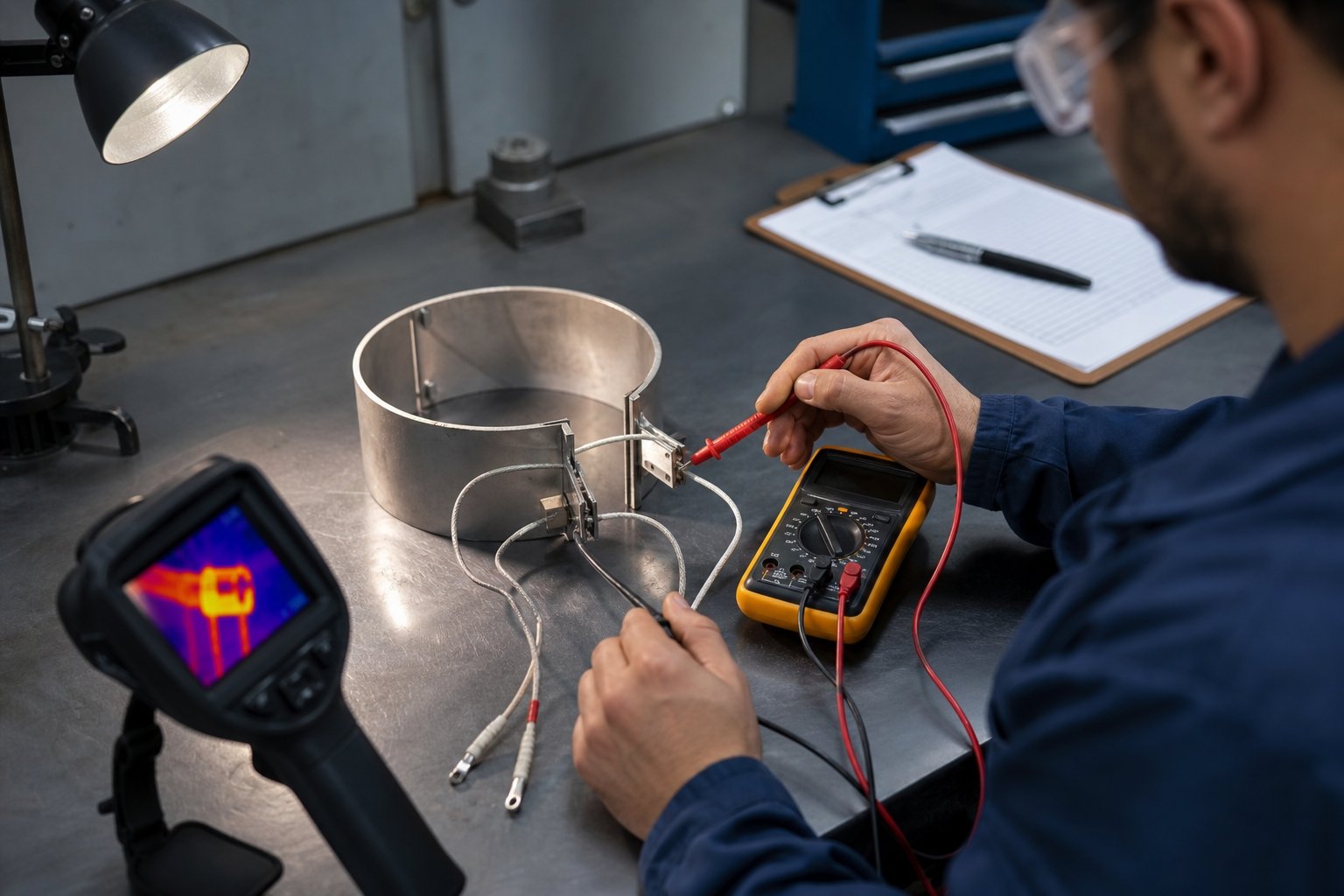
Troubleshooting Common Heater Band Failures
It's 3:00 AM, the injection molding machine throws a temperature alarm, and the maintenance tech finds a dead zone on the barrel. What happens next — systematic diagnosis or blind replacement — determines whether this failure costs you one hour or repeats every two weeks until someone identifies the actual root cause.
Industrial electric band heater failures aren't random events. Forensic analysis across production facilities consistently shows that 90% of premature failures fall into five preventable categories: contamination, poor clamping, incorrect watt density, control system errors, and mechanical wire fatigue. Learning to "read" a failed unit like a crime scene — examining physical symptoms, measuring electrical values, and correlating process data — lets you eliminate the root cause rather than endlessly replacing the symptom.
Diagnosing Burnout and Open-Circuit Failures
Element burnout is the most frequent failure mode. The nichrome resistance wire oxidizes, becomes brittle, and fractures — breaking the electrical circuit permanently. When you disconnect the unit and measure resistance across the lead wires with a digital multimeter, an "OL" (open loop) or infinite resistance reading confirms a burned-open element.
But why did it burn? The physical evidence tells you:
- Air gaps from loose clamping. Rainbow or dark blue discoloration on the outer sheath is the metallurgical fingerprint of extreme overheating. The band generated wattage normally, but trapped heat couldn't transfer into the barrel because of insufficient contact. Internal wire temperatures exceeded 1,200°C and the element melted.
- Contamination between band and barrel. Carbonized polymer residue, hydraulic oil, or scale acts as an insulating layer — functionally identical to an air gap. Black carbon buildup visible inside folded seams confirms this failure path.
- Excessive watt density. If you're pushing more watts through a smaller surface area than the insulation type supports — exceeding roughly 20 W/in² for standard mica or 39 W/in² for a ceramic heater band — the element runs chronically hot even with perfect contact.
- Voltage spikes and power surges. Transient over-voltage events stress the element beyond its design limits. Check facility power quality records if burnouts cluster around specific times or equipment startups.
The diagnostic workflow is straightforward: measure resistance, compare to nameplate rating (calculated as R = V² / P), and then physically inspect the unit for the visual clues above. A heater rated at 240V and 1,000W should measure approximately 57.6 ohms. Deviation beyond ±10% — in either direction — signals trouble even before complete failure occurs.
Resolving Uneven Heating and Hot Spots
When your controller shows the zone is at setpoint but the product exhibits inconsistent melt quality — burn marks on one side, cold slug on the other — the problem usually isn't the controller. It's uneven thermal distribution within the zone itself.
Three scenarios produce this pattern:
- Partially failed element. A section of the resistance wire has thinned or cracked, creating a high-resistance segment that generates less heat than the rest of the coil. The overall zone averages out to setpoint, but the barrel surface has a cold stripe where the damaged section sits.
- Poor barrel-surface contact on one side. A band that's tight at the clamp bolt but loose 180 degrees opposite creates asymmetric heat transfer. One side of the barrel runs hot (good contact) while the opposite runs cold (air gap). This is especially common on nozzle band heaters with small diameters where even slight out-of-round conditions create gaps.
- Incorrect band width leaving coverage gaps. If adjacent bands don't adequately cover the barrel zone — leaving exposed metal between them — that unheated strip creates a cold ring that disrupts the melt temperature profile.
A thermal imaging camera is the fastest diagnostic tool for this category of problem. Scan the barrel circumference with the system at steady-state operating temperature. Hot spots glow brighter on the infrared image, while cold zones appear darker. The pattern immediately tells you whether you're dealing with a contact issue (asymmetric brightness), an element problem (irregular striping), or a coverage gap (cold band between heated sections).
Ground Faults, Short Circuits, and Insulation Breakdown
When a ground-fault breaker trips repeatedly on a specific zone, the insulation barrier between the live element and the grounded metal sheath has been compromised. Current is leaking to ground through a path it shouldn't take — and the protective device is doing its job by cutting power before someone gets hurt.
The three most common causes of insulation breakdown:
- Moisture ingress. Both mica and ceramic are hygroscopic. Humidity, wash-down spray, or steam exposure allows water to penetrate the insulation layers, creating a conductive path. Standard mica band heaters have folded seams that are not hermetically sealed — fluids seep in through capillary action.
- Contamination and carbonization. Molten polymer or hydraulic oil that infiltrates the seams carbonizes at operating temperature. Carbon is electrically conductive, effectively bridging the element to the sheath and causing a violent short to ground.
- Mechanical damage. Impact from dropped tools, overtightened clamps crushing insulation, or vibration-induced wire chafing against the sheath all create paths for current leakage.
The megohmmeter (megger) is your primary diagnostic instrument here. With the unit disconnected from all power, apply 500VDC between the element leads (tied together) and the outer sheath. Readings above 500 megohms indicate healthy insulation. Values between 10 and 500 megohms suggest moisture absorption that may respond to a bake-out procedure (heating the disconnected unit at 120°C for several hours to drive off moisture). Readings below 10 megohms indicate permanent insulation failure requiring replacement.
Use the following quick-reference table to match symptoms to root causes and corrective actions:
| Symptom | Likely Cause | Diagnostic Test | Corrective Action |
|---|---|---|---|
| Multimeter reads "OL" (infinite resistance) across leads | Element burnout — open circuit from overheating | Compare measured ohms to nameplate R = V²/P; inspect for sheath discoloration | Replace unit; clean barrel surface, verify clamp torque, and confirm watt density is within spec |
| Rainbow/blue discoloration on outer sheath | Air gap from loose clamping or contaminated barrel surface | Visual inspection; check clamp bolt torque; verify barrel OD matches band ID | Clean barrel to bare metal, re-install with proper seating, perform hot re-torque after heat-up |
| Ground-fault breaker trips on energization | Insulation breakdown — moisture ingress or carbon tracking | Megger test at 500VDC; inspect seams for black carbon deposits or moisture | Attempt bake-out if reading is 10-500 MΩ; replace if below 10 MΩ or carbon tracking is visible |
| Zone temperature fluctuates erratically at setpoint | Partially degraded element or intermittent connection at terminals | Monitor current draw with clamp ammeter; wiggle-test lead connections under power | Replace band if resistance exceeds nameplate by >10%; re-torque terminal hardware if connection is intermittent |
| Uneven barrel temperature within a single zone (confirmed by IR camera) | Asymmetric barrel contact — tight on one side, air gap on opposite | Thermal imaging scan at steady-state; physical gap check with feeler gauge | Remove, re-clean barrel surface, verify roundness; re-install with uniform clamping using mallet seating technique |
| Blown hole or melted section in sheath casing | Severe arcing short — usually from polymer contamination creating conductive bridge | Visual inspection; check for polymer leak source upstream; megger remaining zones | Fix upstream leak (nozzle seal, barrel flange); upgrade to sealed/encapsulated design for contamination-prone zones |
| Broken wire at terminal exit point | Mechanical fatigue — leads pulled during handling or abraded by vibration | Continuity test from terminal post to element; inspect lead exit point for fracture | Replace unit; route leads with strain relief; add stainless steel braid armor on high-vibration machines |
This table covers the scenarios you'll encounter most frequently — bookmark it or print it for the maintenance cage. The underlying principle across every failure mode is the same: don't just replace the dead unit and walk away. Identify what killed it, eliminate that condition, and the replacement will last years instead of weeks.
Diagnosing a failure accurately also shapes your next decision — where and how to source the replacement. Knowing whether you need a standard mica unit, a sealed nozzle heater, or a higher-rated ceramic design determines the specifications you'll bring to a supplier, and choosing the right supplier makes the difference between a quick turnaround and a frustrating procurement cycle.
How to Source Reliable Replacement Heater Bands
You've diagnosed the failure, identified the root cause, and cleaned the barrel surface. The replacement unit you order next determines whether this fix holds for years or fails again within months. Sourcing a heater band isn't like ordering a commodity bolt from a catalog — dimensions, materials, and termination details must match your process precisely, and the band heater supplier you choose directly impacts lead time, quality, and long-term reliability.
Rushing this step — ordering the cheapest unit with approximate dimensions — is how maintenance teams end up in a cycle of repeat failures. A methodical approach to specification and supplier selection breaks that cycle permanently.
What Information to Prepare Before Ordering
Before reaching out to any band heater manufacturer, gather the following details from the machine. Having this information ready eliminates back-and-forth delays and ensures you receive a unit that fits perfectly on the first attempt:
- Barrel outside diameter (OD) — measured directly from the cold barrel with precision calipers or a pi tape, never from the old heater's ID
- Band width — the axial length the heater must cover, accounting for adjacent zones and obstructions
- Wattage — matched to your process requirements and insulation type limits
- Voltage — typically 120V, 240V, or 480V depending on your plant's electrical system
- Termination type — leads (length and gauge), plug connectors, post terminals, or enclosed junction box
- Thermocouple provisions — hole location, diameter, and whether an integrated sensor is required
- Special features — moisture-resistant seals, high-temperature rating, specific sheath material, or agency certifications (UL, CSA, CE)
What if the OEM part number is unavailable or the original manufacturer no longer exists? This is common on older machines. Reliable heater band suppliers can manufacture replacements from technical drawings, physical samples, photographs, or field-measured dimensions. As custom manufacturing guides emphasize, providing the barrel OD rather than the old heater's ID is critical — thermal warping makes a spent unit an unreliable dimensional reference.
Evaluating Heater Band Suppliers for Quality and Reliability
Not every supplier is equal. A vendor that ships a generic mica band at the lowest price may save $20 on the purchase order — and cost $5,000 in downtime when it fails prematurely due to substandard materials or sloppy tolerances. Here's how to differentiate a quality-focused band heater manufacturer from a commodity vendor:
- Custom manufacturing capability and product range. The best suppliers manufacture across all three primary insulation types — mica, ceramic, and mineral-insulated — and produce custom sizes without excessive minimum order quantities. NANHAIYA, for example, manufactures replacement heater bands based on drawings, samples, photos, or measured dimensions, and their extruder spare parts catalog covers complementary components like thermocouples, injection nozzles, screw tips, check rings, and die heads — enabling single-source ordering that simplifies procurement for maintenance teams.
- Technical support for specification assistance. A supplier that helps you calculate watt density, recommends the correct insulation type, and flags potential fitment issues before manufacturing saves you from costly errors. If the salesperson can't answer basic thermal engineering questions, look elsewhere.
- Lead time and inventory flexibility. Emergency failures demand rapid turnaround. Evaluate whether the supplier stocks standard sizes for immediate shipment and can expedite custom orders when production is down.
- Quality certifications and traceability. ISO 9001 certification, UL recognition, and documented material traceability aren't optional extras — they're indicators that the manufacturer controls their processes and can reproduce consistent quality batch after batch.
- Complementary component sourcing. Suppliers who also stock thermocouples, barrel accessories, nozzle tips, and control components let you consolidate orders and reduce procurement overhead. When one vendor understands your entire barrel-zone assembly, compatibility issues disappear.
The emphasis on single-source capability isn't just about convenience — it's about accountability. When your heater band, thermocouple, and nozzle components come from the same supplier, there's one point of contact if something doesn't perform. No finger-pointing between vendors about whether the heater failed because of a bad thermocouple reading or vice versa.
Ultimately, sourcing replacement heater bands is a decision that compounds over time. A reliable band heater supplier becomes a maintenance partner — one who knows your equipment, anticipates your reorder needs, and delivers units that outlast the competition. Invest the effort upfront to evaluate properly, and you'll spend far less time troubleshooting premature failures and far more time running production.
Frequently Asked Questions About Heater Bands
1. What is the difference between mica, ceramic, and mineral-insulated heater bands?
Mica heater bands are the most economical option, rated for continuous use up to approximately 600°F with watt densities around 35 W/in², making them ideal for general-purpose injection molding and extrusion. Ceramic heater bands use interlocking ceramic tiles that support continuous temperatures of 1,200-1,400°F and higher watt densities while naturally insulating against outward heat loss. Mineral-insulated (MI) bands pack compacted magnesium oxide around the element inside a sealed sheath, delivering rugged performance up to roughly 1,400°F in harsh, high-vibration, or contamination-prone environments. Choosing the right type depends on your process temperature, required watt density, operating conditions, and budget.
2. How long does a heater band last, and what shortens its lifespan?
A properly installed and maintained heater band can last two to three years or longer under demanding production schedules. The primary factors that shorten lifespan include poor barrel-surface contact from loose clamping or contamination, excessive watt density beyond the insulation type's safe ceiling, aggressive on/off thermal cycling from poorly tuned controllers, moisture ingress through unsealed seams, and neglecting periodic hot re-torque of clamping hardware. Implementing a structured preventive maintenance program — including monthly megger tests and quarterly resistance comparisons — can extend service life by up to 300% compared to a run-to-fail approach.
3. How do I know what size heater band to order for my barrel?
Start by measuring the barrel's actual outside diameter with calipers or a pi tape — never rely on nominal machine specs, as machined diameters can differ by 1-3 mm. Then measure the available axial width between flanges, thermowells, or adjacent heaters. Calculate target wattage by multiplying your desired watt density (within safe limits for your insulation type) by the effective heated surface area, subtracting unheated zones at the clamp gap and terminals. Finally, specify voltage, termination style, and any thermocouple provisions. Suppliers like NANHAIYA can manufacture custom replacements from drawings, samples, photos, or field-measured dimensions when OEM part numbers are unavailable.
4. Why does my heater band keep burning out?
Repeated burnouts almost always trace back to one of five root causes: air gaps from loose clamping or a contaminated barrel surface, watt density exceeding the insulation type's safe limit, voltage spikes or power quality issues, incorrect band diameter creating poor thermal contact, or carbonized polymer infiltrating the seams and causing short circuits. To break the cycle, clean the barrel to bare metal before each installation, verify the band's inner diameter matches the barrel OD precisely, perform a hot re-torque after the first heat-up, and confirm your watt density stays within manufacturer-recommended limits — roughly 20 W/in² for standard mica and up to 39 W/in² for ceramic.
5. Can I use a heater band without a temperature controller?
Running a heater band without temperature feedback is strongly discouraged. Without a thermocouple and controller in the loop, the heater operates at full output continuously, risking material degradation, barrel damage, and safety hazards. At minimum, use a thermostat for simple applications like drum heating or pipe tracing. For plastics processing, a PID controller paired with a Type J or Type K thermocouple provides the precise closed-loop control needed to maintain setpoint within tight tolerances, reduce thermal cycling stress on the element, and extend overall heater band service life.
Written by
Nanhaiya Technical Team
Zhoushan Nanhaiya Plastic Machinery Co., Ltd.
The Nanhaiya technical team supports screw and barrel manufacturing projects through application review, technical communication, custom manufacturing coordination, and production and quality control.
Discuss Your Application
Related Articles
More insights on screw barrel technology and plastics processing.

What Nobody Tells You About Screw Barrel For Plastic Machine Design
Oct 10, 2026
Learn how screw barrel for plastic machine design affects melt quality, throughput, and wear life. Covers geometry, resin matching, troubleshooting, and sourcing.
Read Article
Single Screw Extruder for Sheet: Stop Guessing, Start Specifying
Oct 9, 2026
Learn how to specify a single screw extruder for sheet production. Covers screw geometry, resin-specific processing, troubleshooting, and maintenance best practices.
Read Article
PE Pipe Extruder Machine: What Datasheets Won't Tell You
Oct 9, 2026
Learn how a PE pipe extruder machine works, key specs explained, material grade selection, maintenance tips, and buyer guidance beyond the datasheet.
Read ArticleLooking for something else?
Search by material, symptom or product and jump straight to the relevant page.
These are navigation suggestions based on keyword matching — not a quotation, not a delivery commitment, and not a substitute for engineering review. Final specification is confirmed by our engineers against your drawings and processed material.
Need help with screw barrel selection?
Share your machine model, processed material and application. Our team can help with pricing and technical support.