

What an HDPE Pipe Production Line Is and Why It Matters
Imagine a single system that takes raw plastic pellets at one end and delivers finished, pressure-rated pipes at the other — continuously, around the clock. That is exactly what an HDPE pipe production line does, and understanding how it works is the first step toward making a confident capital investment or optimizing an existing operation.
What Is an HDPE Pipe Production Line
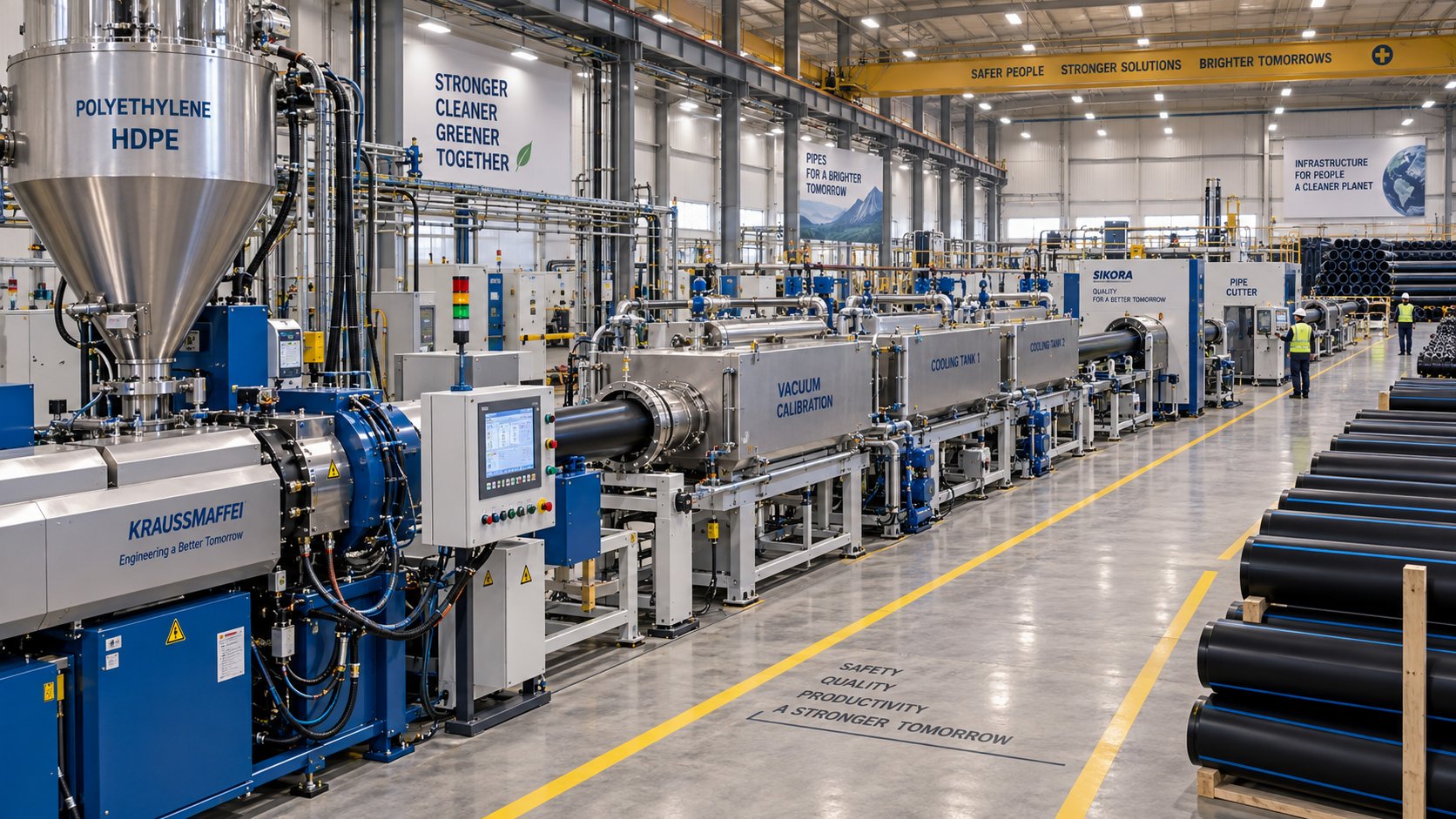
An HDPE pipe production line is an integrated series of machines that converts raw high-density polyethylene resin into finished pipes through continuous extrusion. The process begins with pelletized HDPE resin fed into a heated extruder, where it is melted, homogenized, and forced through an annular die to form a hollow tube. Downstream equipment then sizes, cools, marks, and cuts the pipe to specification. Modern lines can produce extruded polyethylene pipes ranging from small-diameter conduit tubing at 16 mm all the way up to large-bore infrastructure pipes exceeding 1,600 mm. Pressure ratings vary by resin grade and wall thickness, covering everything from low-pressure drainage to PN25 potable water and gas distribution mains. The entire workflow — from granule to stacked or coiled pipe — runs as a single synchronized system, with each station's speed and temperature coordinated by a central PLC control platform.
Why HDPE Pipe Demand Continues to Grow
The global appetite for HDPE pipes shows no sign of slowing. The global HDPE pipes market was valued at roughly USD 24.44 billion in 2025 and is projected to reach USD 37.93 billion by 2034, reflecting a compound annual growth rate of about 5.0%. Several material advantages drive this expansion. HDPE resists corrosion from soil acids, salt water, and chemical effluents — a critical weakness of metal alternatives. Its flexibility allows it to absorb ground movement and seismic activity without cracking. Fusion-weldable joints create leak-free connections that outperform rubber-gasket couplings over decades of service. And unlike rigid PVC, HDPE excels in trenchless installation methods such as horizontal directional drilling, which municipalities increasingly favor to reduce urban disruption and lower carbon footprints.
HDPE pipes can achieve a service life exceeding 50 years, making the production line a long-term capital investment rather than a short-cycle purchase.
These qualities explain why the water supply segment alone commands approximately 42% of the HDPE pipe market, while agricultural irrigation is the fastest-growing application segment. Additional demand comes from broadband conduit deployment, gas distribution networks, and industrial fluid transport — each sector reinforcing the business case for reliable hdpe extrusion capacity.
Who This Guide Is For
Most online resources about this equipment read like manufacturer sales pages — heavy on brand claims, light on the technical depth you actually need. This guide takes a different approach. It is written from a vendor-neutral, buyer-and-operator perspective, structured to serve two distinct audiences. If you are evaluating your first pipe production line, you will find clear explanations of every major component, how resin grades shape your equipment choices, and what specifications truly matter when comparing suppliers. If you already operate a line, the later sections cover process optimization, common troubleshooting scenarios, and maintenance strategies that protect throughput and pipe quality over the long haul. The article follows a progressive-depth structure: it starts with the big picture, moves through each production stage, and finishes with practical selection and maintenance guidance.
The journey from raw pellet to finished pipe involves a surprisingly coordinated sequence of heating, shaping, cooling, and handling steps — each one influencing the quality of the final product in ways that are not always obvious from a spec sheet alone.
How HDPE Pipe Is Manufactured From Granule to Finished Product
Picture a handful of small, milky-white plastic pellets. Within minutes, those granules will travel through a precisely orchestrated pipe extrusion process and emerge at the other end as a rigid, pressure-rated pipe ready for burial underground. Every station along the way plays a specific role, and a hiccup at any point ripples forward into the finished product. Here is how the entire workflow unfolds, stage by stage.
- Raw material handling and feeding
- Melting and extrusion through the barrel
- Die forming, vacuum sizing, and cooling
- Haul-off, cutting, and downstream handling
Raw Material Handling and Feeding
Everything starts at the material hopper. HDPE resin pellets — typically PE80 or PE100 grade — are loaded into a hopper mounted above the extruder, either manually from bags or automatically via a vacuum conveying system in higher-capacity plants. Consistent feeding is critical because even small fluctuations in material delivery translate into wall-thickness variation in the finished pipe.
Most production lines use a gravimetric dosing system that weighs resin in real time and adjusts the feed rate to maintain a target throughput in kilograms per hour. Volumetric feeders are a simpler, lower-cost alternative, but they cannot compensate for bulk-density differences between resin batches. When color or UV stabilization is required, masterbatch concentrate is blended into the virgin resin stream at a controlled ratio — typically 2% to 4% by weight for carbon black in pressure-pipe applications. If the formulation includes hygroscopic additives or recycled HDPE with higher moisture content, an inline drying unit removes residual water before the material reaches the barrel. As industry sources note, moisture trapped in the melt causes bubbles and surface defects that compromise both appearance and structural integrity.
Melting and Extrusion Through the Barrel
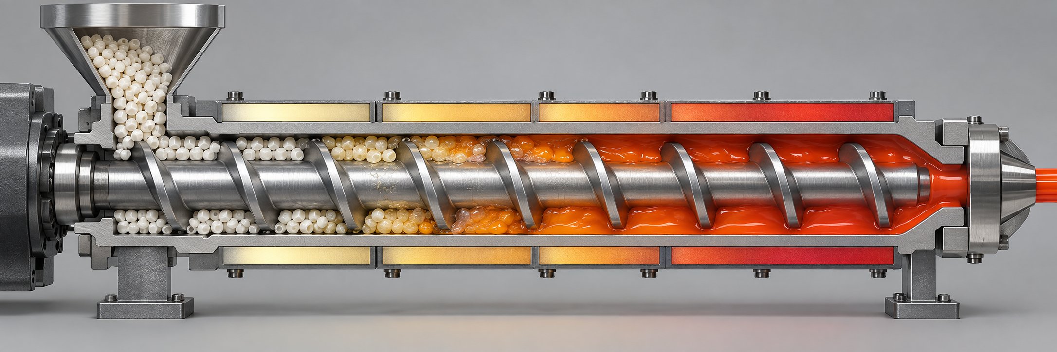
The resin drops from the hopper into the feed throat of the extruder barrel, where a rotating screw takes over. Think of the screw as a carefully engineered conveyor belt that does three jobs in three distinct zones:
- Feed zone — Pellets are picked up and compacted. Barrel temperature here is relatively low, typically 150 - 180 °C, to prevent premature melting that would reduce conveying efficiency.
- Compression zone — The screw channel depth decreases, squeezing the material and generating shear heat. Barrel temperatures climb to 180 - 220 °C as the resin transitions from solid pellets to a viscous melt.
- Metering zone — The now-homogeneous melt is delivered at a uniform pressure and temperature, typically 210 - 230 °C, toward the die. Consistency here determines how evenly the pipe wall forms downstream.
Multiple barrel heating zones — controlled by PID-regulated heater bands and cooling fans — keep each section within a tight temperature window. Back-pressure generated at the die end forces the melt backward slightly, improving mixing and eliminating air pockets. Screw speed is usually set between 20 and 60 RPM, balanced against residence time: spin too fast and the resin exits under-plasticized; too slow and throughput drops. The extruder's performance at this stage essentially dictates the melt quality that every downstream station inherits.
Die Forming, Vacuum Sizing, and Cooling
When the homogeneous melt exits the barrel, it enters the extrusion die — an annular tool that shapes the melt into a hollow tube. Inside the die, spiral or coat-hanger flow channels distribute the polymer evenly around the circumference, while an adjustable die gap controls wall thickness. Getting flow distribution right is essential: uneven distribution causes one side of the pipe to be thicker than the other, a defect known as eccentricity.
The soft, still-molten tube immediately enters a vacuum sizing tank. Here, negative pressure — typically in the range of 0.02 to 0.06 MPa — pushes the pipe's outer surface outward against a precision-machined calibration sleeve, locking in the target outside diameter and roundness. Simultaneously, a water spray or immersion bath begins rapid cooling. As vacuum calibration research highlights, an uncontrolled melt can experience dimensional variance exceeding 15% without this immediate stabilization step. The pipe then passes through one or more additional cooling tanks — spray-type for standard diameters, full-immersion for thick-walled or large-diameter products — where water temperature is held at 15 - 20 °C. Tank length and cooling intensity scale with line speed: a faster line needs longer cooling sections to fully solidify the pipe before it reaches the haul-off.
Haul-Off, Cutting, and Downstream Handling
A caterpillar-style haul-off grips the now-rigid pipe with rubber-padded belts or tracks and pulls it through the entire line at a constant, precisely controlled speed. This speed must stay tightly synchronized with the extruder's output. Pull too fast and you stretch the pipe, thinning the wall; pull too slow and material backs up, causing deformation. In practice, haul-off speed is set approximately 1% to 3% faster than the extrusion rate to compensate for thermal shrinkage as the pipe cools.
Just upstream of the cutting station, an inkjet or hot-foil printer marks each pipe with traceability data — manufacturer code, pipe diameter, pressure class, production date, and the applicable standard (such as ISO 4427 or ASTM F714). These markings are not optional; they are required by virtually every regulatory framework.
The cutting station itself uses a planetary saw or chip-free cutter that travels with the pipe so the line never stops. Planetary saws rotate a blade around the pipe circumference for clean, burr-free cuts on larger diameters, while chip-free guillotine cutters handle smaller sizes without generating plastic shavings that contaminate the work area. After cutting, pipes above roughly 110 mm in diameter are tilted onto an automatic stacking rack, while smaller-diameter pipes — especially those destined for irrigation or cable ducting — are wound onto coils by an automatic winding unit for easier transport and field deployment.
Each of these stages relies on the equipment that precedes it: a poorly plasticized melt sabotages die performance, unstable vacuum sizing undermines dimensional accuracy, and inconsistent haul-off speed erases all the precision built up earlier. That interdependence is exactly why understanding the individual components in detail — their specifications, their wear points, and how they interact — separates a productive line from one that constantly chases quality problems.
Key Components of an HDPE Pipe Extrusion Machine Explained
Knowing the production sequence is one thing. Knowing what to look for inside each machine — the specs that separate a reliable pipe extrusion line from a problematic one — is something else entirely. When you are comparing quotes from multiple suppliers, every component on the line has a handful of critical specifications that directly affect pipe quality, throughput, and long-term operating cost. Let's walk through each major unit, one at a time.
The Extruder — Heart of the Production Line
If the extruder underperforms, nothing downstream can compensate. This single unit determines melt homogeneity, output consistency, and energy efficiency for the entire line.
A single-screw hdpe extruder machine consists of five core subsystems working together:
- Drive motor — Supplies rotational force to the screw. AC inverter-duty motors are standard; higher-efficiency permanent magnet synchronous motors (PMSM) can reduce energy consumption by 10% to 15%.
- Gearbox — Converts motor speed to the high-torque, low-RPM output the screw needs. Thrust bearing capacity is a key spec here because the entire axial force of the melt pushes back against it.
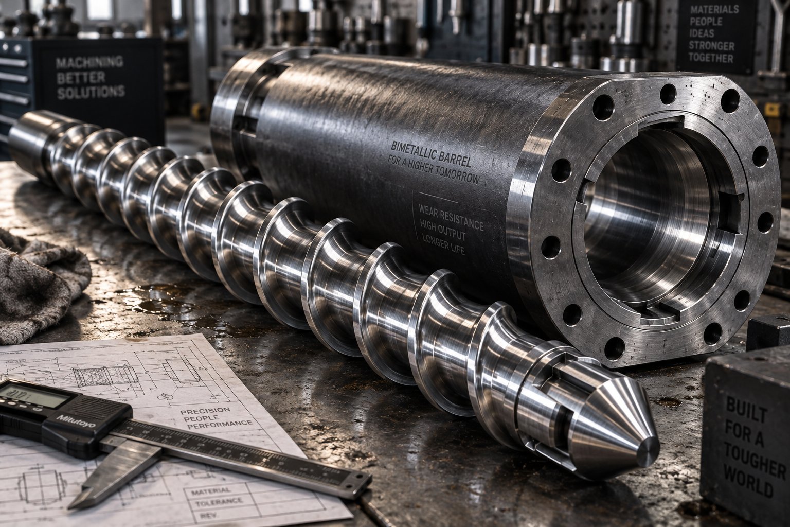
- Barrel — A nitrided or bimetallic steel cylinder fitted with multiple PID-controlled heater bands and cooling fans. Barrel wear over time degrades output and melt quality — a topic covered in depth in the next chapter.
- Screw — The single most important element. Screw diameters for HDPE pipe lines typically range from 45 mm for small conduit up to 120 mm or larger for pipes above 630 mm OD. Output capacity scales roughly with the square of screw diameter, so a 90 mm screw can produce approximately four times the throughput of a 45 mm screw under comparable conditions.
- Heating and cooling system — Ceramic or mica band heaters divided into multiple zones (typically four to six) maintain the barrel temperature profile discussed in the previous chapter. Air-cooling fans on each zone prevent temperature overshoot during steady-state operation.
When evaluating extruders, focus on screw diameter, L/D ratio, motor power, and maximum throughput in kg/h. These four numbers define the machine's capability envelope — and they must align with your target pipe diameter range and production speed.
Extrusion Die and Mandrel Assembly
The die is where shapeless melt becomes a pipe. Inside, a spiral mandrel or basket-weave flow channel distributes the polymer evenly around a 360-degree annulus. Sounds straightforward, but uneven flow distribution is one of the most common causes of wall-thickness variation and pipe eccentricity.
Two design details matter most for buyers. First, the die gap — the annular opening between the mandrel and the outer die ring — directly controls wall thickness. Adjustable centering bolts allow operators to fine-tune concentricity during production. Second, the flow channel geometry determines how uniformly melt reaches every point around the circumference. Spiral mandrel dies are the dominant choice for HDPE pipe because they eliminate the weld-line weakness associated with older spider die designs, where support legs split and recombine the melt stream. For each target pipe diameter range, you will typically need a dedicated die and sizing tooling set, so factor tooling inventory into your capital budget.
Vacuum Sizing Tank, Cooling Tanks, and Haul-Off
These three stations work as a tightly coupled group. If any one of them drifts out of specification, the pipe's dimensions follow.
The vacuum sizing tank houses a precision-machined calibration sleeve that sets the pipe's outer diameter. Vacuum levels — usually 0.02 to 0.06 MPa — push the still-soft extrudate against the sleeve while chilled water sprays begin solidifying the surface. The sleeve material, internal finish, and dimensional tolerance are critical specs because they directly stamp their accuracy onto every meter of pipe produced.
Cooling tanks extend the solidification process. Tank length is driven by line speed and pipe wall thickness: a high-speed line producing thin-walled conduit might need only 6 meters of cooling, while a slow-running line making thick-walled 630 mm pipe could require 12 meters or more. Cooling water temperature is typically maintained at 15 to 20 °C by an external chiller, and consistent water flow across all spray nozzles prevents localized hot spots that cause ovality.
The caterpillar haul-off grips the pipe between synchronized rubber-padded belts and pulls it through the line at a constant speed. You will want to evaluate contact length, clamping force adjustment, and speed-control accuracy. A haul-off with poor speed regulation introduces periodic wall-thickness fluctuations that no upstream adjustment can fix. For large-diameter, heavy pipes, dual-track or multi-pad haul-offs distribute the clamping load to avoid deforming the pipe surface.
Cutting Station, Printer, and Stacker or Coiler
The final stations are easy to overlook during line selection, yet they directly affect product compliance and labor costs.
Cutting systems come in two main types. Planetary saws orbit a circular blade around the pipe, delivering clean, burr-free cuts well suited for medium and large diameters. Chip-free cutters use a shearing or guillotine action that avoids generating plastic swarf — ideal for smaller pipes and cleanroom-adjacent environments. Both types travel with the pipe during the cut so the line runs continuously.
Inkjet or hot-foil printers apply traceability markings — pipe size, SDR, resin grade, production date, and the applicable standard code. These markings are mandatory under ISO 4427, EN 12201, and ASTM standards, so print legibility and adhesion are non-negotiable specs.
Downstream of the cutter, pipes above roughly 110 mm OD are transferred to an automatic tilting and stacking rack that organizes cut lengths for bundling. Smaller-diameter pipes — think irrigation drip lines or fiber-optic conduit — go to an automatic coiler that winds the pipe into compact coils for shipping. Coiler capacity, maximum coil weight, and coil OD are the key specs to match against your product mix.
| Component | Primary Function | Key Buyer Specification |
|---|---|---|
| Single-screw extruder | Melts and homogenizes HDPE resin | Screw diameter, L/D ratio, motor power, max output (kg/h) |
| Extrusion die & mandrel | Shapes melt into a hollow tube | Flow channel design, adjustable die gap, concentricity tolerance |
| Vacuum sizing tank | Sets outer diameter and roundness | Calibration sleeve tolerance, vacuum range, tank length |
| Cooling tanks | Solidifies pipe wall uniformly | Total tank length, water temperature control, spray uniformity |
| Caterpillar haul-off | Pulls pipe at constant speed | Contact length, clamping force range, speed accuracy (%) |
| Cutting station | Cuts pipe to length without stopping the line | Saw type (planetary vs. chip-free), max pipe OD, cut accuracy |
| Printer | Applies mandatory traceability markings | Print method (inkjet/hot-foil), character resolution, adhesion |
| Stacker or coiler | Organizes finished pipes for storage/shipping | Max pipe weight/length (stacker) or max coil OD/weight (coiler) |
This component-level understanding gives you a concrete checklist when sitting across from a supplier. Yet one unit on this list — the extruder — hides a layer of engineering detail that deserves its own deep dive: the relationship between screw geometry, barrel specifications, and the throughput your line can actually deliver.
Extruder Specifications and Screw Barrel Design Demystified
Screw diameter and motor power grab most of the attention on a spec sheet — they are big, easy-to-compare numbers. But the performance difference between a mediocre hdpe extruder and a genuinely capable one often hides in subtler parameters: the length-to-diameter ratio of the screw, the geometry of its flight channels, and the condition of the barrel it rotates inside. These details determine melt quality, energy efficiency, and how long the machine maintains peak output before wear takes its toll.
What L/D Ratio Means and Why It Matters
You will see "L/D" stamped on nearly every extruder nameplate, yet many buyers gloss over the number. Here is what it actually tells you. The L/D ratio divides the effective working length of the screw by its outer diameter. A 45 mm screw with a 33:1 L/D, for instance, has a barrel length of roughly 1,485 mm. A 90 mm screw at the same ratio stretches to about 2,970 mm.
Why does this matter for extruded pipe manufacturing? HDPE is a semi-crystalline polymer with a relatively high melting point and narrow processing window. Thorough, uniform plasticization requires sufficient residence time inside the barrel — and residence time is largely a function of screw length. A higher L/D ratio gives the resin more time to absorb heat, shear, and mixing energy before reaching the die. The practical benefits include more complete melting with fewer unplasticized particles, better dispersion of color masterbatch and UV stabilizers, and reduced melt-temperature variation across the pipe wall.
Most hdpe extrusion machine configurations use L/D ratios in the 30:1 to 38:1 range. Some newer designs push to 42:1, claiming 20-30% higher output capacity under the same screw diameter thanks to an extended metering section that stabilizes melt pressure and reduces surging. The trade-off is real, though: longer barrels cost more to manufacture, consume more energy to heat, and require more floor space. For standard PE100 pipe production from virgin resin, a 33:1 to 36:1 L/D ratio represents a practical sweet spot — enough processing length for quality melt without excessive capital or energy overhead.
A higher L/D ratio extends residence time and improves melt homogeneity, but every additional unit of length adds to equipment cost, energy demand, and plant footprint.
Screw Geometry and Barrel Wear Considerations
The L/D ratio sets overall processing length, but what happens within that length depends on screw geometry — specifically, three design parameters:
- Feed depth — A deeper feed channel picks up more pellets per revolution, boosting solids-conveying rate. Too deep, however, and the pellets compact poorly, trapping air.
- Compression ratio — The ratio of feed-zone channel depth to metering-zone channel depth, typically 2.5:1 to 3.5:1 for HDPE. This compression generates the shear heat that melts the resin and eliminates air pockets.
- Metering zone design — A properly proportioned metering section delivers the melt at uniform pressure and temperature to the die. Too short, and pressure fluctuates; too long, and excessive shear can degrade the polymer.
Even a perfectly designed screw eventually wears — and so does the barrel it turns inside. The flight clearance between the screw tip and the barrel wall is critical. On a new 100 mm extruder, that clearance is roughly 0.1 mm per side. As abrasive fillers, recycled HDPE with contaminants, or simple metal-to-metal contact erode the flight tips and barrel liner, the clearance widens. The consequences are measurable: research from Plastics Technology shows that a worn screw forces operators to increase RPM to maintain the same output rate, which in turn raises discharge temperature. At a certain wear threshold, rate must be reduced by as much as 13% to keep melt temperature within the process window — a direct hit to line profitability and capacity.
The good news is that barrel and screw replacement does not mean buying an entirely new extruder. Sourcing precision-manufactured custom and replacement single screw barrels for pipe extrusion — such as those offered by NANHAIYA — can restore original flight clearances, output rates, and melt quality at a fraction of the cost of a full machine replacement. A barrel with an iron-based bimetallic liner typically lasts about three times the service life of a screw, but both should be inspected regularly and replaced before quality degradation becomes visible in finished pipe.
Matching Extruder Size to Target Output
Screw diameter, L/D ratio, and motor power work together to determine how many kilograms of HDPE your line processes per hour. Imagine these three specs as a triangle: change any one side and the throughput picture shifts. A larger screw diameter moves more material per revolution. A higher L/D ratio improves melt quality at a given speed. And motor power caps how fast you can turn the screw before the drive stalls under load.
The table below provides general industry ranges to help you match extruder size to your target pipe diameter and production speed. These figures represent typical values across multiple equipment suppliers — your actual results will depend on resin grade, die tooling, and downstream cooling capacity.
| Screw Diameter | Typical L/D Ratio | Approximate Output (kg/h) | Suitable Pipe Diameter Range |
|---|---|---|---|
| 45 - 65 mm | 30:1 - 33:1 | 100 - 300 | 16 - 110 mm |
| 75 - 90 mm | 33:1 - 36:1 | 300 - 600 | 110 - 400 mm |
| 90 - 120 mm | 33:1 - 38:1 | 500 - 900 | 315 - 800 mm |
| 120 - 150 mm | 33:1 - 38:1 | 800 - 1,200+ | 630 - 1,600 mm |
Notice the overlap in the middle ranges — a 90 mm extruder, for example, can serve both medium and the lower end of large-diameter production depending on wall thickness and line speed. This flexibility matters if your product mix spans multiple pipe sizes, because a well-specified mid-range extruder paired with interchangeable die tooling can cover a broader catalog than two smaller machines.
Keep in mind that motor power should scale proportionally. A general benchmark is roughly 4 to 6 kW of installed motor power per kilogram-per-hour of output for HDPE, though high-efficiency drive systems can push the lower end of that range. Under-powering the motor leads to torque limitations at higher screw speeds, capping your real-world throughput well below the screw's theoretical capacity.
Extruder specifications set the production ceiling for the entire line — but the resin you feed into that extruder has its own set of demands. Different HDPE grades carry different melt temperatures, crystallization behaviors, and processing sensitivities, all of which influence how you configure barrel temperatures, screw speed, and cooling intensity.
HDPE Resin Grade Selection and Its Impact on Production
You could own the most finely tuned extruder on the market, but feed it the wrong resin — or process the right resin at the wrong parameters — and you will spend your days chasing wall-thickness alarms and surface defects. Resin grade is not just a purchasing decision; it directly shapes how you configure barrel temperatures, screw speed, die tooling, and cooling intensity across the entire line. Understanding the differences between PE80, PE100, and PE100-RC is essential for anyone running — or planning to invest in — polyethylene extrusion equipment.
PE80, PE100, and PE100-RC — What the Grades Mean
HDPE pipe resins are classified by their MRS (Minimum Required Strength) — a measure of the material's long-term hydrostatic strength at 20 °C over a 50-year design life. Think of MRS as the resin's pressure-bearing fingerprint: it tells you how much internal stress the pipe wall can sustain indefinitely without failure.
- PE80 — MRS of 8.0 MPa. This grade has a slightly lower molecular weight and less dense crystalline structure than PE100, resulting in moderate compressive strength. It remains a practical choice for low-pressure drainage, agricultural irrigation, and residential water connections where operating pressures stay well under 10 bar.
- PE100 — MRS of 10.0 MPa. With a tighter molecular chain structure and higher density (typically 0.955 - 0.965 g/cm³), PE100 delivers 25% higher pressure capacity than PE80 at the same wall thickness. This is the current global standard for municipal water supply and gas distribution pipe. In North America, the ASTM equivalent designation is PE4710, classified under ASTM D3350 cell classification rather than the ISO MRS system, but the performance tier is comparable.
- PE100-RC — Same 10.0 MPa MRS as standard PE100, but with enhanced resistance to slow crack growth (SCG). The "RC" stands for "crack resistant," and these resins are engineered with modified molecular architectures that dramatically improve point-load and scratch tolerance. This matters for trenchless installation methods — directional drilling, pipe bursting, sliplining — where the pipe surface may contact rocks or abrasive soils during insertion.
Here is the practical consequence for your production line: higher-MRS resins enable thinner pipe walls for the same pressure rating. A PE100 SDR 11 pipe achieves PN 16 (16 bar), while a PE80 pipe needs a thicker wall — SDR 9 — to reach the same rating. Thinner walls mean less material per meter of pipe, faster cooling, and higher line speeds. But they also demand tighter die gap control and more precise wall-thickness monitoring, because the margin for error shrinks as the wall gets thinner.
How Resin Choice Affects Processing Parameters
Switching from PE80 to PE100 is not as simple as swapping bags at the hopper. The two grades behave differently inside the barrel, and those differences cascade through every downstream station.
Melt temperature range is the first variable. PE80 typically processes at barrel temperatures of 180 - 210 °C, while PE100 resins — with their higher crystalline melting point — generally require 200 - 230 °C. The window within that range is narrower for PE100: go too low and you get unmelted particles; go too high and you risk thermal degradation that weakens the pipe's long-term pressure performance. PE100-RC grades can be even more sensitive, as their modified chain structures sometimes require specific temperature profiles recommended by the resin manufacturer.
Screw speed sensitivity is the second factor. PE100's higher melt viscosity means it generates more shear heat at the same RPM. Operators accustomed to running PE80 at a particular screw speed often find that the same speed produces an excessively hot melt with PE100, pushing discharge temperatures beyond the acceptable window. The practical fix is to reduce RPM slightly and compensate with adjusted heater band setpoints — but this only works if your extruder's L/D ratio provides enough residence time for complete plasticization at the lower speed.
Cooling rate requirements round out the picture. PE100's higher crystallinity means the pipe needs more carefully controlled cooling to develop optimal mechanical properties. Cooling too fast can lock in residual stresses that reduce long-term crack resistance; cooling too slowly drops your line speed and throughput. For extruded HDPE pipe in PE100 grades, cooling water temperature is typically held at 15 - 20 °C, and spray distribution across the cooling tanks must be uniform to prevent differential crystallization that shows up as ovality or warping.
In short, the resin you choose does not just determine what your pipe can do in the field — it determines how your entire line must operate to produce that pipe consistently.
Selecting Resin for Your Target Application
Matching the right grade to your end-use application avoids both over-specification (wasting money on resin performance you do not need) and under-specification (producing pipe that fails to meet the applicable standard).
The decision framework comes down to four factors:
- Target pressure class — For pressure systems above PN 10 (water mains, gas distribution), PE100 is the clear choice. Its higher MRS allows thinner walls and larger internal bore at the same pressure rating, translating to more flow capacity per meter of pipe. PE80 remains suitable for lower-pressure applications like PN 6 gravity drainage or PN 8 irrigation lines.
- Installation method — If the pipe will be installed via horizontal directional drilling, pipe bursting, or any technique that exposes the surface to scratching and point loads, specify PE100-RC. The enhanced slow-crack-growth resistance ensures that minor installation damage does not compromise the pipe's 50-year design life.
- Pipe diameter — Large-diameter pipes (above 630 mm OD) are almost exclusively produced in PE100 because the material savings from thinner walls become significant at scale. For small-diameter service connections, the cost difference between PE80 and PE100 may be marginal, making PE100 the pragmatic default.
- Regulatory standard requirements — Your target market dictates the standard. ISO 4427 and EN 12201 govern water supply pipe in most international markets. ISO 4437 and EN 1555 cover gas distribution. ASTM D3035 and ASTM F714 apply in North America. Each standard specifies which material grades are acceptable for a given pressure class and application, so verify compliance before committing to a resin supplier.
For most new hdpe extrusions destined for municipal infrastructure, PE100 has become the default specification worldwide. PE80 still holds a role in cost-sensitive, low-pressure applications, and PE100-RC earns its premium wherever installation conditions are harsh. Getting this choice right at the project planning stage prevents expensive mid-production resin changes — and ensures your line's barrel temperatures, screw speed, and cooling setup are dialed in from day one.
Resin grade shapes what happens inside the barrel, but it is not the only equipment-level decision that affects melt quality and output. The type of extruder itself — single-screw versus twin-screw — introduces a completely different set of trade-offs that deserve a head-to-head comparison.
Single-Screw vs Twin-Screw Extruders for HDPE Pipe
Every hdpe extrusion line starts with an extruder, and the very first fork in the road is a fundamental one: do you go with a single-screw or a twin-screw design? The question comes up in nearly every buyer consultation, and the answers you find online tend to lean heavily toward whichever machine the author happens to sell. Here is a balanced, application-driven comparison to help you decide based on your actual production needs — not someone else's catalog.
Single-Screw Extruder Advantages for HDPE Pipe
Walk into ten HDPE pipe plants around the world, and you will find a single-screw extruder running in at least nine of them. There are good reasons for that dominance.
Single-screw extruders have a simpler mechanical architecture — one screw rotating inside one barrel, driven by one gearbox. Fewer moving parts translate directly into lower capital cost, easier maintenance, and fewer opportunities for something to break at 2 a.m. on a Friday. The design excels at conveying pelletized resin, which is exactly what you feed an HDPE pipe line 99% of the time. HDPE pellets are uniform in size, free-flowing, and easy for a single screw's feed zone to pick up and compact efficiently. There is no need for the aggressive self-wiping action or forced feeding that twin-screw machines provide.
From an operational standpoint, single-screw configurations deliver the high-pressure pumping capability that pipe extrusion demands. As industry specialists note, single-screw extruders are high-pressure devices capable of generating and stabilizing pressures above 3,000 psi — far exceeding the 1,500 psi ceiling typical of twin-screw machines. That pressure-building ability is essential for pushing a viscous HDPE melt through an annular die and into the vacuum sizing tank at a stable, consistent rate.
Spare parts availability further tips the scale. Single-screw barrels and screws are widely manufactured across global supply chains, so replacement lead times are shorter and costs are lower. For a pe pipe extrusion line running continuous shifts, the ability to source a replacement barrel or screw quickly can mean the difference between a planned weekend swap and weeks of unplanned downtime.
When a Twin-Screw Extruder Makes Sense
Does this mean twin-screw extruders have no place in HDPE pipe production? Not at all — but the scenarios where they add genuine value are specific rather than general.
Twin-screw extruders shine when intensive mixing is the priority. Their two intermeshing, co-rotating screws create a self-wiping action that distributes fillers, fibers, and additives far more uniformly than a single screw can achieve. If your operation processes heavily filled compounds — say, HDPE blended with 40% or more calcium carbonate for cost reduction — a twin-screw design disperses those fillers without the agglomeration problems a single screw would struggle to overcome.
In-line compounding of recycled HDPE blends is another strong use case. Post-consumer recycled HDPE often arrives as flake or regrind with inconsistent bulk density, residual moisture, and trace contaminants from mixed-polymer streams. A co-rotating twin-screw extruder handles these challenges through its starve-fed design, multi-stage venting capability, and superior devolatilization. The corotating intermeshing twin-screw extruder can remove trapped moisture and volatiles through vacuum ports positioned along the barrel — a feature that eliminates the need for a separate pre-drying step in many recycling applications.
Multi-material or co-extruded pipes requiring intensive mixing of dissimilar polymers before entering the die head also benefit from twin-screw processing. Imagine producing a pipe with a recycled HDPE core layer and a virgin PE100 outer skin: the recycled stream may need compounding, degassing, and filtration before it can form a structurally sound layer. A twin-screw extruder handles all three within a single barrel.
Trade-Offs to Consider
These capabilities come at a cost — and not just the purchase price. Twin-screw extruders are mechanically more complex. Two intermeshing screws with tight geometric tolerances demand more frequent inspection and more precise maintenance. The screws themselves are modular, built from individual elements stacked on splined shafts, and replacing worn mixing elements requires specialized knowledge and inventory. As a result, maintenance complexity and spare parts costs run significantly higher than for a comparable single-screw setup. Twin-screw machines are also more vulnerable to damage from contaminants: a stray metal bolt in the feed stream can lock up two intermeshing screws far more catastrophically than it would a single screw with wider flight clearances.
Making the Right Choice for Your HDPE Pipe Extruder Machine
So how do you decide? The framework is straightforward once you strip away the marketing noise. Ask yourself three questions:
- What am I feeding the extruder? — Virgin or lightly recycled HDPE pellets? A single-screw extruder handles this efficiently and reliably. Heavily filled compounds, post-consumer regrind, or multi-polymer blends that need devolatilization? A twin-screw design earns its premium.
- What pressure does my die require? — Standard HDPE pipe dies need consistent high-pressure delivery. Single-screw machines are inherently better pumps and build pressure more efficiently at lower screw speeds, generating less shear heat in the process.
- What is my total cost of ownership? — Factor in not just the purchase price but ongoing maintenance, spare parts, energy consumption, and operator training. For standard pipe production, the single-screw path delivers a lower lifetime cost almost every time.
The table below lays out the key criteria side by side to make your comparison concrete.
| Criteria | Single-Screw Extruder | Twin-Screw Extruder |
|---|---|---|
| Capital cost | Lower — simpler construction, fewer components | Higher — complex intermeshing screw and barrel system |
| Maintenance complexity | Low — single screw, standard barrel, widely available parts | High — modular screw elements, tight tolerances, specialized spares |
| Mixing capability | Moderate — adequate for pelletized resin and masterbatch | Excellent — self-wiping action, distributive and dispersive mixing |
| Pressure generation | High (3,000+ psi) — ideal for die feeding | Low to moderate (typically under 1,500 psi) — may need a gear pump |
| HDPE pipe suitability | Dominant choice for standard pipe from virgin or lightly recycled resin | Niche — best for in-line compounding or heavily filled formulations |
| Ideal use case | Standard PE80/PE100 pipe production, single-layer extrusion | Recycled HDPE compounding, filled compounds, reactive processing |
For the vast majority of hdpe extrusion line installations worldwide — producing standard water, gas, or conduit pipe from virgin PE100 pellets — a well-specified single-screw extruder with a quality barrel and properly designed screw geometry remains the most cost-effective, reliable, and proven path. Twin-screw technology earns its place in operations that genuinely need intensive mixing or devolatilization, but bolting one onto a standard pipe line adds cost and complexity without a proportional return.
The extruder type sets your line's processing foundation, yet even within a single-screw configuration, the downstream equipment can look dramatically different depending on what kind of pipe you are producing. A single-layer water pipe, a multi-layer co-extruded product, and a corrugated drainage pipe each demand their own unique line layout — and those differences go well beyond simply swapping out the die.
Multi-Layer and Specialty HDPE Pipe Line Configurations
A standard single-layer pe pipe production line handles the lion's share of water and gas pipe manufacturing. But the moment your product mix expands — multi-layer structures for cost optimization, corrugated profiles for stormwater drainage, or jumbo-diameter mains for municipal infrastructure — the line layout changes in ways that affect floor space, capital budget, and operator skill requirements. Let's break down the three most common specialty configurations and what each one actually adds to the base setup.
Co-Extrusion Lines for Multi-Layer HDPE Pipe
Imagine you want a pipe with a virgin PE100 outer skin for pressure performance and regulatory compliance, but a core layer made from recycled HDPE to cut material costs. Or perhaps you need a colored identification stripe — blue for water, yellow for gas — fused permanently into the outer surface. These are the problems co-extrusion solves.
A 2-layer or 3-layer co-extrusion pe extrusion line adds one or two secondary extruders alongside the main unit. Each extruder feeds its own melt stream into a multi-layer die head, where concentric flow channels merge the layers into a single pipe wall before the melt exits the die. The layers bond thermally while still molten, creating a monolithic structure with no adhesive interface.
Each layer serves a distinct purpose:
- Outer layer — Typically virgin PE100 for UV resistance, pressure rating compliance, and surface finish quality. A thin striped layer can be co-extruded on top for visual identification.
- Core layer — Often recycled or off-spec HDPE, reducing raw material cost by 20% to 40% on the most expensive component of the pipe — the resin itself.
- Inner layer — Virgin material again for food-contact compliance in potable water applications, or a smooth surface to minimize hydraulic friction.
The downstream equipment — vacuum sizing, cooling tanks, haul-off, and cutting — remains largely the same as a single-layer line. The real complexity sits upstream: synchronizing melt flow from multiple extruders so that each layer maintains a consistent, target thickness around the full circumference. A mismatch in melt pressure between extruders shows up immediately as uneven layer distribution, which can compromise both structural integrity and regulatory compliance.
Corrugated Double-Wall Pipe Production
Corrugated pipes look nothing like solid-wall pressure pipe, and their production lines reflect that difference. The corrugated outer wall provides high ring stiffness for buried applications — stormwater drainage, sewer systems, cable protection — while a smooth inner wall ensures low-friction flow.
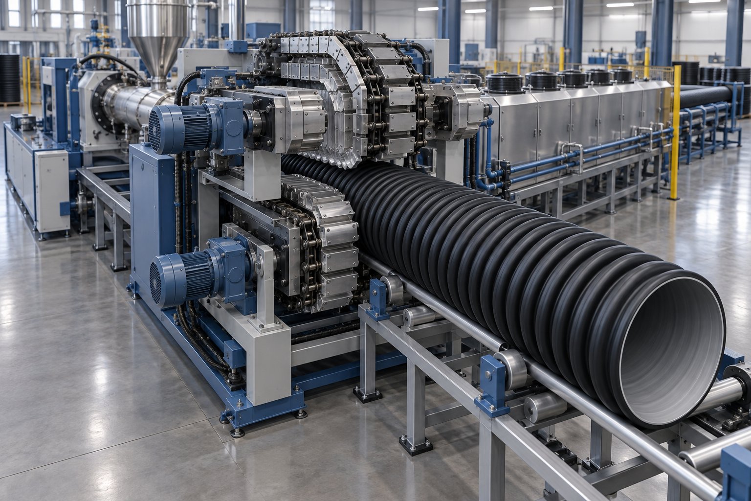
The biggest hardware change is the corrugator. This machine replaces the vacuum sizing tank entirely. Two continuously moving chains of precision-machined mold blocks clamp around the freshly extruded tube. Vacuum pressure — typically -0.03 to -0.08 MPa — pulls the still-soft outer wall into the mold cavities, forming the characteristic ribbed profile while the plastic is still formable. The mold blocks travel at a speed precisely matched to the extrusion rate; even a slight mismatch produces irregular corrugation geometry or wall thinning.
The die head is also different. In a double-wall corrugated polyethylene pipe production line, a co-extrusion die simultaneously delivers two melt streams: one for the corrugated outer wall and one for the smooth inner wall. These streams fuse inside the corrugator to create the bonded double-wall structure. Line speeds for corrugated pipe are generally slower — around 1 to 10 m/min depending on diameter — because the mold-block forming process requires more contact time than open vacuum calibration.
Downstream, the differences continue. Large-diameter corrugated pipes are rigid and cannot be coiled, so stacking systems replace winding units. Cutting stations must handle the ribbed profile without crushing the corrugation, which sometimes calls for specialized clamping fixtures.
Large-Diameter and Thick-Wall Pipe Considerations
Scaling a line up to produce pipes above 630 mm OD is not simply a matter of bolting on a bigger die. Nearly every station on the line grows — in size, cost, and energy demand.
The extruder itself needs a larger screw diameter (typically 120 mm or above) and a more powerful motor to deliver the throughput required for thick-walled, large-bore pipe. Output rates for these lines commonly range from 1,200 to over 2,000 kg/h. Haul-off units expand from standard dual-track configurations to 8- or even 16-track caterpillar systems that distribute clamping force across the pipe's circumference, preventing the deformation or slippage that lighter haul-offs would cause on a pipe weighing hundreds of kilograms per meter.
Cooling becomes the dominant bottleneck. A thick-walled 1,200 mm pipe holds an enormous mass of molten polymer that takes far longer to solidify than a thin-walled 110 mm pipe. Advanced lines address this with internal pipe cooling (IPC) technology, which draws chilled air through the pipe's interior while spray tanks cool the exterior. Even with IPC, cooling sections can stretch the total line footprint to 50 to 80 meters in length. Line speeds drop accordingly — you might run a 1,600 mm line at under 1 m/min compared to 10+ m/min for small-diameter conduit.
Energy consumption scales steeply as well. Electrical power requirements for a large-diameter line can reach 280 to 350 kW per 1,000 kg/h of output, and cooling water circuits may demand 40 to 60 cubic meters per hour. Factory planning must account for reinforced flooring, heavy-duty gantry cranes for handling finished pipe, and expansive outdoor storage — logistics that add meaningfully to the total project cost beyond the machinery itself.
| Configuration | Number of Extruders | Die Type | Key Downstream Difference | Typical Applications |
|---|---|---|---|---|
| Single-layer solid wall | 1 | Standard spiral mandrel die | Vacuum sizing tank + spray cooling tanks | Pressure water, gas distribution, general-purpose pipe |
| Multi-layer co-extrusion (2- or 3-layer) | 2 - 3 | Multi-layer co-extrusion die | Same vacuum sizing and cooling; added layer-thickness monitoring | Recycled-core pipe, striped identification pipe, potable water with inner skin |
| Corrugated double-wall | 2 (outer wall + inner wall) | Co-extrusion die adapted for corrugator | Corrugator with mold-block chains replaces vacuum sizing tank | Stormwater drainage, sewer systems, cable protection conduit |
| Large-diameter solid wall (above 630 mm) | 1 (heavy-duty, 120 mm+ screw) | Large spiral mandrel die with IPC | Extended cooling sections (50-80 m), multi-track haul-off, gantry handling | Municipal water mains, mining slurry, sea outfalls |
Each of these configurations builds on the same extrusion fundamentals covered earlier in this guide — melt, shape, cool, pull, cut. The differences lie in how many melt streams you manage, how you form the pipe geometry, and how much cooling capacity the line demands. Choosing the right configuration locks in your capital investment and plant layout, but it also determines your quality control requirements — because the tighter tolerances and multi-layer structures of specialty lines demand more sophisticated inline measurement and stricter compliance with international standards.
Quality Assurance and Standards Compliance on the HDPE Pipe Extrusion Line
Producing pipe that looks right is not the same as producing pipe that passes certification. A wall that measures 0.3 mm too thin at one point, an ovality deviation invisible to the naked eye, or an oxidative stability shortfall buried deep in the polymer — any of these can turn a seemingly good production run into a rejected batch or, worse, a field failure years down the road. The difference between a profitable hdpe plant and one drowning in rework comes down to what you measure, when you measure it, and which standards define "good enough."
Inline Measurement and Monitoring Systems
Catching a defect after the pipe is cut, stacked, and cooling in the yard is expensive. Catching it while the pipe is still moving through the line costs almost nothing — you simply adjust a parameter and the next meter of extrusion pipe comes out within spec. That is the logic behind inline measurement, and modern lines offer several technologies working in concert.
Ultrasonic wall-thickness measurement is the workhorse of inline quality control. Sensors mounted at the vacuum sizing tank exit or just downstream bounce high-frequency sound waves through the pipe wall and measure the return time. Because the speed of sound through HDPE is well characterized, the system calculates wall thickness at multiple points around the circumference — typically 4 to 8 measurement axes — and reports min, max, and average values in real time. As ultrasonic measurement specialists note, thickness is HDPE's "strength code," directly impacting pressure resistance and chemical stability. Any drift beyond the tolerance specified by the applicable standard triggers an alarm or, in closed-loop configurations, automatically adjusts die centering bolts or extruder output to bring the wall back into range.
Laser diameter gauges sit further downstream and scan the pipe's outer profile at high speed — often thousands of measurements per second — to report outside diameter and ovality. These non-contact sensors detect dimensional shifts far faster than manual calipers ever could, and they log every reading for traceability records that auditors and end customers increasingly demand.
Ovality monitoring is sometimes integrated into the laser gauge and sometimes handled by a dedicated station. It compares the maximum and minimum diameters measured in a single cross-section and flags any deviation beyond the standard's permitted tolerance — typically 1% to 1.5% of nominal OD for pressure pipe.
Gravimetric control systems close the loop at the front end. By continuously weighing the resin consumed per unit of time and comparing it against the pipe's target mass-per-meter, the system detects output drift before it even shows up as a dimensional change. If the mass-per-meter drops, it could mean the haul-off is pulling too fast or the extruder output has dipped — either way, the controller responds before the pipe leaves the cooling tank out of spec.
Together, these systems create a closed-loop feedback architecture: measurement instruments detect deviations, the PLC adjusts extruder speed, haul-off rate, or vacuum level, and the next few meters of pipe self-correct. The practical payoff is dramatic. Lines equipped with full closed-loop control routinely hold wall-thickness variation within +/- 0.1 mm, reduce scrap rates to under 1%, and generate the digital quality records that ISO-certified operations require.
Relevant International Standards for HDPE Pipe
Every inline measurement target and every post-production test protocol traces back to a specific standard. Sounds bureaucratic? In reality, these documents are your production blueprint — they define the dimensional tolerances, pressure ratings, and testing requirements that directly determine how you set up the line and what you inspect.
The challenge is that different geographic markets and end-use applications reference different standards. Here is a practical map of the ones you are most likely to encounter:
- ISO 4427 — Water supply. The primary international standard for PE pipes used in potable water and raw water conveyance. It covers material classification, dimensions, mechanical requirements, and fitness-for-purpose testing. Parts 1 through 5 address everything from general requirements to system fitness.
- ISO 4437 — Gas supply. The gas-industry counterpart to ISO 4427, specifying requirements for PE piping systems carrying gaseous fuels at pressures up to 10 bar. Stricter traceability and joint-testing requirements reflect the higher consequences of failure in gas applications.
- EN 12201 — Water supply (European). The harmonized European standard that parallels ISO 4427 and has superseded the earlier EN 13244 series. It governs PE pipe and fittings sold across EU member states and is commonly referenced in tenders throughout the Middle East, Africa, and Southeast Asia as well.
- EN 1555 — Gas supply (European). Covers PE piping systems for gaseous fuels within the European market, including pipes, fittings, valves, and system fitness.
- ASTM D3035 — North American water pipe (controlled OD). Defines PE pipe based on outside-diameter-controlled dimension ratios (DR). Widely specified for water distribution in the United States and Canada.
- ASTM F714 — Large-diameter PE pipe. Covers HDPE pipe from 12 inches (305 mm) through 65 inches (1,650 mm) OD, commonly referenced for municipal water mains, force mains, and industrial applications across North America.
Why does this matter at the production-line level? Each standard specifies allowable wall-thickness tolerances, minimum burst pressures, ovality limits, and marking requirements. Your inline gauges must be calibrated to those tolerances. Your cutting station's length accuracy must meet the standard's delivery-length specs. And your printer must encode the exact information — resin designation, SDR, pressure class, production date, and the standard reference itself — that the relevant standard mandates. A line configured to meet ISO 4427 tolerances may not automatically satisfy ASTM F714 requirements, because the two systems define dimensions and testing criteria differently. If you are exporting pipe to multiple markets, you will need to verify compliance against each applicable standard independently.
Post-Production Testing Methods
Inline monitoring catches process drift in real time, but it cannot verify every property that determines whether a pipe will survive 50 years underground. That is where post-production laboratory testing comes in — a set of destructive and non-destructive evaluations performed on sample pipes pulled from each production run.
Hydrostatic pressure testing is the most fundamental qualification. Sample lengths are capped, filled with water, and pressurized to a specified level at a controlled temperature — then held for a defined duration. Short-term burst tests per ASTM D1599 push the pipe to failure in minutes to verify minimum burst strength. Long-term sustained-pressure tests per ASTM D1598 hold constant pressure for 1,000 hours or more, confirming that the pipe resists creep rupture under continuous loading. Pressure regression testing per ASTM D2837 goes further still, testing multiple samples at different stress levels to extrapolate the pipe's 50-year hydrostatic design basis (HDB) — the statistical foundation for every pressure rating printed on the pipe.
Tensile testing per ISO 6259 measures the pipe material's yield strength, elongation at break, and tensile modulus. These values confirm that the resin's mechanical properties survived the extrusion process intact. Significant deviations from the resin manufacturer's data sheet values can indicate thermal degradation, contamination, or insufficient plasticization — all flags that point back to extruder settings or barrel condition.
Oxidative induction time (OIT) measurement per ISO 11357-6 evaluates how well the pipe's antioxidant package has survived processing. A small sample is heated in a differential scanning calorimeter (DSC) under an oxygen atmosphere, and the time until the onset of oxidative degradation is recorded. A low OIT value — typically below 20 minutes for PE100 pipe — signals that thermal history during extrusion consumed too much of the stabilizer, potentially shortening the pipe's field service life.
Slow-crack-growth resistance tests address the most insidious long-term failure mode. The Pennsylvania Notch Test (PENT) per ASTM F1473 applies a constant tensile load to a notched specimen at 80 °C and measures hours to failure. High-performance PE100 resins typically achieve PENT values exceeding 1,000 hours, while PE100-RC grades can reach well beyond 10,000 hours. The full-notch creep test (FNCT) per ISO 16770 serves a similar purpose under the ISO framework. These tests confirm that the pipe's resistance to brittle fracture — the type of failure that occurs silently underground over years — meets the design intent.
A pipe that passes burst testing but fails slow-crack-growth evaluation may survive pressure, yet crack under point loads from rocks or soil movement years after installation.
Additional tests round out the picture depending on the target application: ring stiffness testing per ISO 9969 for non-pressure drainage pipe, carbon black content and dispersion analysis per ISO 18553 for UV-stabilized products, and environmental stress-crack resistance (ESCR) testing per ASTM D1693 for pipes exposed to surfactants or chemical environments.
Taken together, inline monitoring and post-production testing form two layers of defense. The first catches process drift before it produces non-conforming pipe. The second confirms that the finished product meets the full spectrum of mechanical, chemical, and long-term durability requirements specified by the applicable standard. Neither layer alone is sufficient — and any hdpe pipe extrusion line that skips either one is gambling with product quality and regulatory compliance.
Quality systems define what "good" looks like, but even the best-monitored line eventually encounters problems — a surface defect that appears without warning, a gradual output decline nobody noticed until throughput dropped 10%, or a confusing mismatch between two suppliers' line specifications. Solving those problems efficiently, maintaining the line proactively, and choosing the right equipment in the first place are the practical skills that separate experienced operators from everyone else.
Troubleshooting, Maintenance, and Selecting the Right HDPE Pipe Line
You have dialed in your barrel temperatures, verified your resin grade, and confirmed your inline gauges are reading within tolerance. Then, three hours into a shift, the wall-thickness alarm fires. Or the pipe surface develops a fine sawtooth texture that was not there yesterday. Or your output rate has quietly dropped 8% over the past month and nobody flagged it until the production report landed on your desk.
These are not hypothetical scenarios — they are Tuesday morning for most hdpe pipe manufacturing process operators. The difference between a plant that resolves issues in minutes and one that burns entire shifts chasing symptoms comes down to structured troubleshooting, consistent preventive maintenance, and having made the right equipment choices before the line was ever installed.
Common Production Problems and How to Solve Them
Most defects on an HDPE pipe production line trace back to a small set of root causes. The trick is knowing where to look first. Here are the issues operators encounter most frequently, organized as quick-reference problem-cause-solution sets you can walk through on the shop floor.
- Wall-thickness variation
Likely causes: Die centering is off, haul-off speed is fluctuating, or melt temperature is uneven across barrel zones. A worn screw or barrel can also cause inconsistent melt delivery — predictive maintenance data shows that screw wear changes the relationship between RPM and output rate, creating micro-surging that shows up as periodic thickness swings.
Solution: Check die centering bolts and recenter using ultrasonic wall-thickness readings at four or more points. Verify haul-off speed stability. Review barrel zone temperatures for deviations greater than 3 °C from setpoint. If all process settings check out, measure screw flight clearance at the next scheduled shutdown — widening clearance is the hidden culprit operators overlook most often. - Surface defects — sharkskin or melt fracture
Likely causes: Excessive shear stress at the die exit. Sharkskin appears as fine, regularly spaced ridges running along the pipe length, while melt fracture produces more severe spiral or wavy distortion. Both result from the melt velocity exceeding the polymer's critical shear rate at the die land.
Solution: Reduce extrusion speed to lower the shear rate. Raise die-zone temperature by 5 - 10 °C to decrease melt viscosity at the exit point. If the problem persists, inspect the die land for scratches or buildup — contamination and die-land wear create localized stress concentrations that trigger surface defects even at otherwise acceptable speeds. - Ovality (out-of-roundness)
Likely causes: Uneven vacuum distribution inside the sizing tank, asymmetric cooling water spray patterns, or a misaligned calibration sleeve. Gravity sag on large-diameter pipes with insufficient internal support can also contribute.
Solution: Verify vacuum level consistency across all zones in the sizing tank. Check that spray nozzles are not clogged or misdirected — a single blocked nozzle on one side of the tank creates a temperature asymmetry that pulls the pipe out of round. Confirm that the calibration sleeve is centered and its bore matches the target OD specification. - Bubbles or voids in the pipe wall
Likely causes: Moisture in the resin, trapped air from poor feed-zone compaction, or degraded polymer generating volatile byproducts.
Solution: Verify resin moisture content — HDPE itself is not hygroscopic, but recycled feedstock and certain masterbatch additives can carry significant moisture. If moisture is confirmed, add or verify the inline dryer upstream of the hopper. For trapped air, check that screw back-pressure is sufficient and that the feed throat is not bridging. - Gradual output decline
Likely causes: Progressive barrel and screw wear widening the flight clearance, heater band degradation reducing melt temperature accuracy, or screen pack loading increasing back-pressure. This problem is insidious because it develops slowly — often over weeks or months — and operators compensate by increasing screw RPM, which accelerates wear further.
Solution: Track output rate versus screw RPM over time. A healthy extruder maintains a consistent kg/h-per-RPM ratio. When that ratio drops by 10-15%, the screw or barrel — or both — has worn past the point of efficient operation and needs replacement.
Preventive Maintenance Priorities
Reactive maintenance — waiting for something to break — is the most expensive way to run any extrusion operation. A catastrophic screw seizure, for example, can mean 8 to 72 hours of unplanned downtime plus emergency repair costs that dwarf the price of a planned replacement. The smarter approach is a structured preventive maintenance program that catches wear and degradation before they affect output or pipe quality.
Here are the maintenance actions that deliver the highest return for an hdpe pipe production line, ordered by impact:
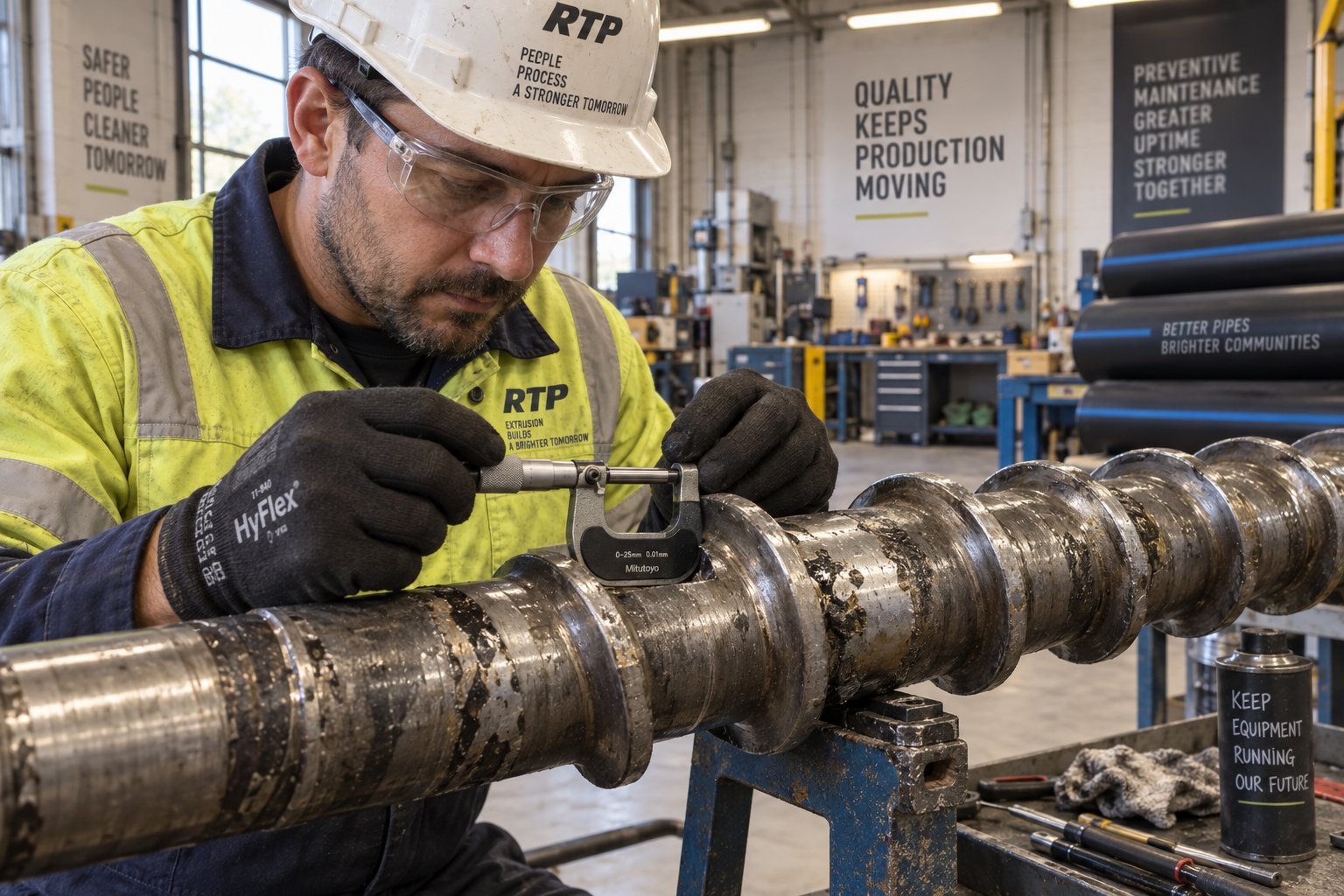
- Barrel and screw inspection for wear — Measure screw flight OD and barrel ID at each scheduled shutdown using bore gauges and micrometers. Compare readings to the original dimensions. Industry benchmarks suggest that when flight clearance exceeds roughly 0.25 mm (0.010 inches) per side on a standard single-screw extruder, output efficiency has degraded enough to justify replacement. Proactive barrel and screw replacement prevents the gradual output loss and quality degradation that many operators accept as "normal" — a hidden cost that compounds with every production hour.
- Gearbox oil analysis — Submit oil samples for spectroscopic analysis every 2,000 to 3,000 operating hours. Elevated iron or bronze particle counts signal bearing or gear wear long before vibration becomes noticeable. Catching gearbox issues early avoids the cascading damage that turns a $500 bearing replacement into a $15,000 gearbox rebuild.
- Heater band continuity checks — Use a clamp ammeter to verify current draw on each barrel heater zone during operation. A heater drawing zero or reduced current has failed or is failing, forcing adjacent zones to compensate and creating the temperature imbalances that cause wall-thickness variation and surface defects.
- Vacuum pump servicing — Inspect vacuum pump oil levels, vane wear, and inlet filters monthly. A vacuum pump that cannot maintain target pressure inside the sizing tank directly translates to OD drift and ovality in the finished pipe.
- Cooling-water filtration and flow verification — Clogged filters and scaled nozzles reduce cooling efficiency progressively. Check water flow rates and spray pattern uniformity weekly. Replace inline filters and descale nozzles on a scheduled basis rather than waiting for a quality alarm.
Of all these items, barrel and screw condition deserves the most attention — because wear here degrades every meter of pipe the line produces, yet the decline is so gradual that it often goes unnoticed until output has dropped significantly. Partnering with a specialist supplier who can deliver precision-fit replacements on a predictable schedule is one of the most practical steps an operator can take. For instance, sourcing precision single screw barrels for pipe extrusion from NANHAIYA ensures that custom-fit or OEM-replacement barrels are available without the long lead times that turn a planned maintenance window into weeks of downtime. NANHAIYA manufactures single screw barrels for pipe, film, sheet, and recycling extrusion lines, so the replacement is engineered to match your extruder's exact specifications rather than a generic approximation.
Choosing the Right Production Line for Your Project
Whether you are evaluating your first line or adding capacity, the selection process benefits from a disciplined checklist rather than a gut feel. Here are the criteria that experienced buyers weigh most heavily — roughly in the order they should be addressed:
| Selection Criterion | What to Evaluate | Why It Matters |
|---|---|---|
| Target pipe range | Minimum and maximum OD, wall thickness (SDR), and pipe type (solid wall, multi-layer, corrugated) | Determines die tooling inventory, extruder size, and downstream equipment configuration |
| Required output | Target throughput in kg/h or meters/hour for each pipe size in your product mix | Sizes the extruder, cooling section length, and haul-off capacity |
| Resin type | PE80, PE100, PE100-RC, or recycled HDPE blends | Affects extruder type (single vs. twin screw), barrel temperature profile, and screw geometry requirements |
| Available floor space | Total line length (including cooling), width for stacking, and ceiling height for hoppers | Large-diameter lines can exceed 60-80 meters; corrugated lines need space for the corrugator and mold-block storage |
| Utility capacity | Electrical supply (kW), cooling water volume (m3/h), compressed air | Undersized utilities cap real-world throughput regardless of machine capability |
| Total cost of ownership | Purchase price + energy consumption + maintenance costs + spare parts availability + expected wear-component replacement frequency | The cheapest line upfront often becomes the most expensive line over five years if spare parts are scarce or energy efficiency is poor |
That last row — total cost of ownership — is where many first-time buyers stumble. A line quoted 15% below its competitors looks attractive until you discover that replacement barrels require a 16-week lead time from a single-source factory, or that the motor draws 20% more power than a comparable unit with a high-efficiency drive. Experienced operators know that wear components — barrels, screws, calibration sleeves, and haul-off belts — are consumables with predictable replacement cycles. Building a reliable supply chain for those parts before the line is even commissioned prevents the scramble that inevitably follows the first wear-related quality dip.
A final piece of advice for anyone deep in the selection process: request reference site visits. Seeing a line run your target pipe size, at your target speed, with your target resin tells you more in 30 minutes than any specification sheet can convey in 30 pages. Ask the host operator what broke first, what they would change, and how responsive the supplier has been after the sale. Those answers — honest, unscripted, and grounded in daily production reality — are worth more than any brochure.
The best production line is not the one with the most impressive spec sheet — it is the one that still runs reliably, efficiently, and within tolerance on its 10,000th hour of operation.
Frequently Asked Questions About HDPE Pipe Production Lines
1. What are the main components of an HDPE pipe production line?
An HDPE pipe production line consists of eight core components working in sequence: a single-screw extruder that melts and homogenizes HDPE resin, an extrusion die and mandrel assembly that shapes the melt into a hollow tube, a vacuum sizing tank that locks in the pipe's outer diameter using negative pressure and a precision calibration sleeve, spray or immersion cooling tanks that solidify the pipe wall, a caterpillar haul-off that pulls the pipe at a constant synchronized speed, a cutting station (planetary saw or chip-free cutter), an inkjet or hot-foil printer for mandatory traceability markings, and a stacker or automatic coiler for finished pipe handling. Each component's specifications — from screw diameter and L/D ratio on the extruder to calibration sleeve tolerance on the sizing tank — must be matched to your target pipe diameter, wall thickness, and production speed.
2. How do I choose between a single-screw and twin-screw extruder for HDPE pipe production?
For standard HDPE pipe production using virgin or lightly recycled PE80 or PE100 pellets, a single-screw extruder is the proven, cost-effective choice used in roughly 90% of pipe plants worldwide. Single-screw designs offer lower capital cost, simpler maintenance, superior pressure generation (above 3,000 psi versus roughly 1,500 psi for twin-screw), and widely available replacement parts such as barrels and screws. Twin-screw extruders become justified only in specific scenarios: processing heavily filled compounds with 40%+ mineral content, in-line compounding of post-consumer recycled HDPE flake requiring devolatilization, or producing multi-material pipes needing intensive dispersive mixing. The decision ultimately hinges on your feedstock type, required die pressure, and total cost of ownership including spare parts and maintenance complexity.
3. What is the ideal L/D ratio for an HDPE pipe extruder?
Most HDPE pipe extruders operate with L/D (length-to-diameter) ratios between 30:1 and 38:1, with the 33:1 to 36:1 range representing the practical sweet spot for standard PE100 pipe production from virgin resin. A higher L/D ratio provides longer residence time inside the barrel, resulting in more thorough melting, better masterbatch dispersion, and reduced melt-temperature variation — all critical for HDPE's semi-crystalline structure. Some newer extruder designs push to 42:1, claiming 20-30% higher output capacity under the same screw diameter. However, longer barrels increase equipment cost, energy consumption, and floor space requirements. When selecting an L/D ratio, balance melt quality needs against your capital budget and available plant layout.
4. How often should extruder barrels and screws be replaced on an HDPE pipe line?
There is no universal replacement calendar because wear rates depend on resin type, filler content, screw speed, and barrel metallurgy. Instead, operators should monitor screw flight clearance at each scheduled shutdown using bore gauges and micrometers. Industry benchmarks indicate replacement is justified when the clearance between the screw flight tip and barrel wall exceeds approximately 0.25 mm (0.010 inches) per side. At that point, output efficiency has degraded measurably — often requiring increased RPM to maintain the same throughput, which raises melt temperature and accelerates further wear. Bimetallic barrel liners typically last about three times longer than screws. Partnering with a specialist manufacturer like NANHAIYA for custom and replacement single screw barrels ensures precision-fit parts are available without extended lead times, keeping planned maintenance windows short and predictable.
5. What international standards apply to HDPE pipe production?
The applicable standard depends on your target market and pipe application. For water supply, ISO 4427 is the primary international standard, while EN 12201 is the harmonized European equivalent. Gas distribution pipes fall under ISO 4437 internationally and EN 1555 in Europe. In North America, ASTM D3035 covers outside-diameter-controlled PE water pipe, and ASTM F714 addresses large-diameter PE pipe from 305 mm to 1,650 mm OD. Each standard defines dimensional tolerances, allowable pressure ratings, material classification requirements, and mandatory testing protocols — including hydrostatic pressure testing, tensile testing, and oxidative induction time (OIT) measurement. Your production line's inline gauges, cutting accuracy, and printer markings must all be configured to meet the specific tolerances of whichever standard governs your end market.
Written by
Nanhaiya Technical Team
Zhoushan Nanhaiya Plastic Machinery Co., Ltd.
The Nanhaiya technical team supports screw and barrel manufacturing projects through application review, technical communication, custom manufacturing coordination, and production and quality control.
Discuss Your Application
Related Articles
More insights on screw barrel technology and plastics processing.

What Nobody Tells You About Screw Barrel For Plastic Machine Design
Oct 10, 2026
Learn how screw barrel for plastic machine design affects melt quality, throughput, and wear life. Covers geometry, resin matching, troubleshooting, and sourcing.
Read Article
Single Screw Extruder for Sheet: Stop Guessing, Start Specifying
Oct 9, 2026
Learn how to specify a single screw extruder for sheet production. Covers screw geometry, resin-specific processing, troubleshooting, and maintenance best practices.
Read Article
PE Pipe Extruder Machine: What Datasheets Won't Tell You
Oct 9, 2026
Learn how a PE pipe extruder machine works, key specs explained, material grade selection, maintenance tips, and buyer guidance beyond the datasheet.
Read ArticleLooking for something else?
Search by material, symptom or product and jump straight to the relevant page.
These are navigation suggestions based on keyword matching — not a quotation, not a delivery commitment, and not a substitute for engineering review. Final specification is confirmed by our engineers against your drawings and processed material.
Need help with screw barrel selection?
Share your machine model, processed material and application. Our team can help with pricing and technical support.