

What Is Film Blowing and Why It Dominates Flexible Packaging
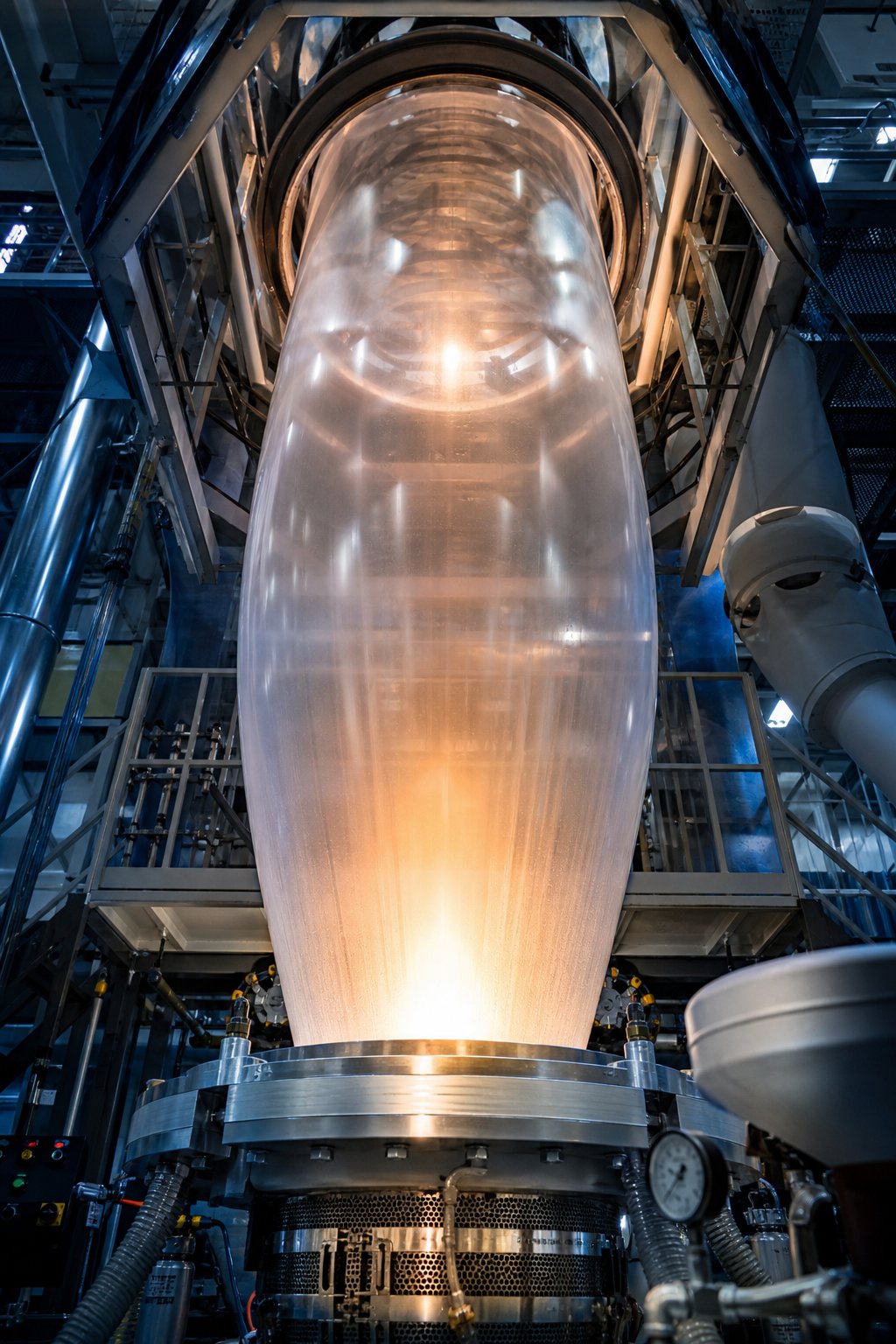
Imagine taking a glob of hot, molten plastic and inflating it like a balloon until it becomes a paper-thin tube stretching several stories high. That, in essence, is film blowing - a continuous extrusion process in which molten polymer is pushed through a circular die, inflated with internal air pressure into a thin-walled tube called a bubble, cooled, collapsed flat, and wound into rolls of layflat or tubular film. It is the single most widely used method for converting raw plastic resin into the flexible films you encounter every day.
What Film Blowing Actually Means
At its core, blown film extrusion follows a straightforward sequence. Plastic resin pellets are melted inside an extruder at high temperature. The molten plastic is then forced through an annular (ring-shaped) die, forming a continuous tube. Air is introduced into the center of that tube, expanding it into a large-diameter bubble. As the bubble rises, it cools and solidifies, after which it is flattened by a collapsing frame and nip rollers before being wound into finished rolls.
How does this differ from other film extrusion methods? The main alternative - cast film extrusion - pushes molten resin through a flat slot die onto a chilled metal roller. Cast processes excel in optical clarity and tight thickness tolerance, but they stretch the film primarily in one direction. Blown film, by contrast, stretches the material in two directions simultaneously (both across and along the bubble), producing a tougher, more balanced film. That biaxial orientation is a key reason why this process dominates global flexible film production.
The numbers confirm that dominance. The global polyethylene film market was valued at $44.29 billion in 2024 and is projected to reach $81.77 billion by 2035, growing at a 5.73% CAGR. Within that market, blown film holds the largest share by operation mode, outpacing cast film and other techniques. LDPE and LLDPE - the two resin families most commonly processed through film blowing - together account for the bulk of polyethylene film output worldwide.
Why Film Blowing Matters Across Industries
You might associate plastic film with grocery bags, but the reach of blown extrusion film extends far beyond the checkout counter. Its unique combination of strength, barrier performance, and format flexibility makes it indispensable across a surprisingly broad range of sectors:
- Food packaging - Stand-up pouches, cereal liners, frozen food bags, and fresh produce wraps that protect flavor and extend shelf life.
- Agriculture - Greenhouse covers, silage bags, mulch films, and fertilizer packaging that improve crop yields and resource efficiency.
- Construction - Vapor barriers, house wraps, and protective sheeting that shield structures from moisture and contaminants.
- Medical and pharmaceutical - Sterile device pouches, IV bag overwraps, and cleanroom packaging where consistency and safety are non-negotiable.
- Industrial stretch and shrink wrap - Pallet wraps, machine covers, and transit packaging that secure goods through complex supply chains.
This versatility is no accident. Because operators can adjust bubble diameter, film thickness, and resin blends on the fly, a single blown film line can serve multiple markets with minimal changeover. That flexibility, paired with relatively lower equipment costs compared to cast lines of similar output, explains why the process remains the backbone of global flexible packaging production.
With such a wide footprint across industries, the quality of every finished roll traces back to the physics happening inside the bubble itself - the interplay of heat, air pressure, and molecular orientation that gives blown film its signature toughness.
The Science Behind Bubble Formation and Biaxial Orientation
That signature toughness does not appear by chance. It is engineered into the film during a brief but critical window - the few seconds between when molten polymer exits the die and when it solidifies into a finished tube. Understanding what happens inside that window is the difference between producing mediocre film and producing film with genuinely balanced mechanical properties.
How the Bubble Forms and Expands
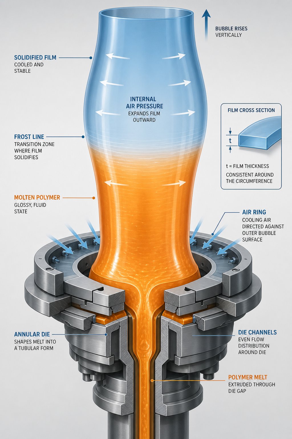
Picture the molten polymer leaving the annular die as a thick-walled, slow-moving tube - still soft, still hot, and still structurally unimpressive. At this point, the material has no meaningful orientation. It is simply a cylindrical curtain of melt, typically emerging from a die gap of roughly 0.4 mm (0.015 in), with its molecular chains arranged more or less randomly.
The transformation begins the instant air is introduced through the center of the die mandrel. This trapped internal air pressure inflates the soft tube outward, stretching it circumferentially much like inflating a cylindrical balloon. Simultaneously, an air ring positioned around the outside of the die directs a high-volume stream of cooling air over the bubble's outer surface. The air ring serves a dual purpose: it removes heat from the expanding polymer and it helps stabilize the bubble geometry so the tube does not wobble, drift, or collapse as it rises.
On higher-output lines, an Internal Bubble Cooling (IBC) system supplements the external air ring by circulating cooled air inside the bubble itself. IBC systems can boost output rates by roughly 50% compared to external-only cooling, because they accelerate solidification from both sides of the film wall at once.
As the bubble rises and cools, you will notice a visible transition on its surface - a ring-shaped boundary where the polymer shifts from a glossy, transparent melt to a slightly hazy, solidified film. This boundary is called the frost line. In semi-crystalline polymers like polyethylene, the frost line marks the zone where the polymer temperature drops below the softening range and crystallization begins. Its height above the die is not just a visual curiosity - it is one of the most important quality indicators on the entire line. A stable frost line at a consistent height signals uniform cooling and steady process conditions. If it drifts up and down, operators can expect thickness fluctuations, inconsistent crystallinity, and compromised optical and mechanical properties in the finished roll.
Understanding Blow-Up Ratio and Its Impact
So what is blow up ratio, exactly? The blow-up ratio (BUR) is defined as the ratio of the final bubble diameter to the die diameter. If a die has a 200 mm diameter and the inflated bubble reaches 600 mm in diameter, the BUR is 3:1. It is one of the single most influential parameters in blown film technology because it directly controls how much the polymer is stretched in the transverse direction (TD) - the direction perpendicular to the travel of the film.
Typical industrial BUR values range from 1.5:1 to 4:1, depending on the resin being processed and the target application. LDPE, with its excellent melt strength and bubble stability, can tolerate higher blow-up ratios comfortably. HDPE and LLDPE often run at moderate ratios because their melt rheology makes the bubble more sensitive to instability at extreme expansion levels. Pushing BUR too high for a given resin can cause the bubble to oscillate, "breathe," or even tear - a scenario every operator learns to avoid.
The blow up ratio governs TD orientation, but it does not act alone. The draw-down ratio (DDR) - determined by the speed of the haul-off nip rollers relative to the melt exit velocity at the die - controls how much the film is stretched in the machine direction (MD). Increase haul-off speed while keeping output constant, and the film gets thinner and more MD-oriented. Together, BUR and DDR create a biaxial orientation pattern that is the defining mechanical advantage of blown film over many competing processes.
Why does biaxial orientation matter so much? When polymer chains are stretched in two directions simultaneously, the resulting molecular alignment distributes load-bearing capacity across the entire film plane rather than concentrating it along a single axis. The practical result is a film with more balanced tear strength, better puncture resistance, and improved barrier properties compared to a film oriented in only one direction. This is precisely why a blown polyethylene bag can withstand rough handling that would split a purely MD-oriented cast film of the same thickness.
Biaxial orientation during blowing gives the film balanced mechanical properties in both directions, something that cannot be replicated by cast extrusion alone.
Getting the BUR-to-DDR balance right is part science, part craft. A higher BUR increases TD strength and improves thickness uniformity around the bubble circumference, but it also widens the layflat - which may or may not suit downstream converting equipment. A higher DDR boosts MD orientation and increases line productivity, yet excessive draw can make the film prone to MD splitting. Experienced operators adjust these two ratios in tandem, watching the frost line and bubble shape as real-time feedback on whether the orientation balance is where it needs to be.
This interplay between expansion, draw, and cooling determines the molecular architecture locked into every meter of finished film. Yet none of it happens without the right hardware delivering molten polymer to the die at precisely the right temperature, pressure, and flow rate - which brings the focus squarely onto the equipment train that makes it all possible.
Complete Equipment Train of a Blown Film Line
Every blown film extrusion machine is, at its core, a carefully orchestrated chain of components. Remove one link or let it fall out of specification, and the defect echoes all the way to the finished roll. Whether you are evaluating a new blown film machine for a greenfield plant or auditing an existing line for upgrades, understanding what each station does - and why its performance tolerances matter - is essential.
Extruder and Feed System
The journey starts at the hopper, a funnel-shaped reservoir mounted on top of the extruder barrel. Resin pellets flow from the hopper by gravity - or through a gravimetric feeder that weighs and meters them in real time - into the throat of the barrel. Gravimetric feeders are especially important on co-extrusion lines and when blending virgin resin with additives or recycled content, because even small fluctuations in feed rate translate directly into thickness variation in the finished film.
Inside the barrel sits the screw - the true workhorse of the system. A single-screw extruder is the standard for most polyethylene film blowing operations, although twin-screw configurations appear in specialty compounding applications where aggressive mixing or reactive extrusion is required. The screw is divided into three functional zones, each with a distinct job:
- Feed zone - Accepts solid pellets from the hopper and conveys them forward. Channel depth is deepest here to maximize solids intake.
- Compression zone - The channel depth decreases progressively, compacting the pellets against the heated barrel wall. Friction and conducted heat melt the resin while increasing pressure.
- Metering zone - The shallowest section, designed to deliver a fully homogenized melt at uniform pressure and temperature to the die. Consistency in this zone is critical - any pressure surge or thermal spike here will appear as a gauge band or gel in the film downstream.
Surrounding the barrel are multiple heating zones, each independently controlled by heater bands and thermocouples. Typical film-grade barrels run three to five zones, with temperatures climbing from relatively cool at the feed throat (to prevent premature melting and bridging) to the target melt temperature near the discharge end. On LDPE lines, for example, barrel temperatures commonly range from about 160 degrees C at the feed to 200-220 degrees C at the metering zone. Precise thermal control across these zones ensures that the polymer reaches the die as a uniform, bubble-ready melt rather than a patchwork of hot spots and under-melted regions.
Die, Air Ring, IBC, and Downstream Equipment
From the extruder discharge, the melt passes through a screen changer - a filtration device containing metal mesh screens that trap contaminants, gels, and unmelted particles. Think of it as the last quality gate before the melt enters the die. Screen changers can be manual slide-plate types on smaller film blowing machine setups, or continuous hydraulic units on high-output blown film lines where uninterrupted production is a priority.
The filtered melt then enters the annular die. Modern blown film lines overwhelmingly use spiral mandrel dies, where the melt is distributed through a series of helical channels carved into the mandrel surface. These overlapping spirals ensure that the polymer spreads evenly around the full 360-degree circumference of the die gap, eliminating the weld lines and thickness bands that plagued older spider and side-fed designs. Die gap, lip geometry, and internal flow-channel polish all influence film uniformity - and reputable blown film extrusion machine manufacturers invest heavily in precision machining at this stage.
Sitting immediately above (or around) the die exit is the air ring. It directs a controlled curtain of ambient or chilled air against the outer surface of the emerging bubble, extracting heat and stabilizing the bubble geometry. Dual-lip air rings offer finer control by splitting the airflow into two independently adjustable streams, letting operators fine-tune cooling intensity at different heights above the die. For lines demanding maximum throughput, an Internal Bubble Cooling (IBC) system circulates cooled air inside the bubble simultaneously, dramatically accelerating solidification. According to industry data on IBC technology, these systems improve thickness uniformity and can raise output rates significantly while reducing energy consumption compared to external-only cooling.
Above the frost line, a bubble cage or calibration basket surrounds the solidified bubble with guide rollers or low-friction panels. Its purpose is simple but important: keep the bubble centered and prevent it from swaying in ambient air currents, which would cause tracking problems and wrinkles at the winder.
The bubble then enters the collapsing frame - commonly an A-frame or tent-frame arrangement of angled panels that gradually flatten the round tube into a layflat configuration. Proper collapsing geometry is essential; if the panels apply uneven pressure or the frame angle is too steep, the film develops edge creases that persist through every downstream operation.
Nip rollers sit at the top of the collapsing frame. These counter-rotating rubber-covered rolls pinch the flattened bubble, sealing the internal air volume and pulling the film upward at a controlled speed. The nip also establishes the draw-down ratio discussed earlier, so roller speed and pressure must be tightly regulated. Many modern lines add an oscillating haul-off that slowly rotates or traverses the nip point, distributing any residual gauge variation around the roll rather than stacking it into a single band.
Before winding, some lines route the film through a corona treater - an optional inline unit that bombards the film surface with electrical discharge. Corona treatment raises surface energy, improving ink adhesion for subsequent printing or lamination. It is not required for every application, but for any film headed to a flexographic or rotogravure press, it is virtually indispensable.
Finally, the treated layflat reaches the winder, which rolls the finished film onto cores at constant tension. Surface winders, center winders, and gap winders each handle different film types and roll diameters. Tension control is critical here - too tight and the film stretches or blocks (sticks to itself), too loose and telescoping ruins the roll.
Laid out end to end, the full equipment sequence of a blown film extrusion machine looks like this:
- Hopper and gravimetric feeder
- Single-screw extruder (or twin-screw for specialty compounds)
- Screen changer
- Annular die (spiral mandrel type)
- Air ring and IBC system
- Bubble cage or calibration basket
- Collapsing frame (A-frame or tent frame)
- Nip rollers and haul-off unit
- Corona treater (optional, for printable films)
- Winder
Each station in this sequence feeds the next, and the tolerances compound. A reliable blown film machine supplier understands that a line is only as good as its weakest component - which is why the best-engineered systems match extruder output capacity, die flow geometry, cooling rate, and winding tension into one integrated package rather than bolting together mismatched subsystems.
With the hardware mapped out, a natural question follows: how does the film produced on this equipment stack up against film made on a completely different type of line? The answer depends on whether you are comparing blown film to its closest rival - cast film extrusion - and which performance criteria matter most for your application.
Blown Film vs Cast Film Extrusion Compared
Both processes start the same way - plastic pellets enter an extruder, melt into a viscous fluid, and flow toward a die. From that point forward, though, a blown cast comparison reveals two fundamentally different engineering philosophies for turning that melt into finished film.
Fundamental Process Differences
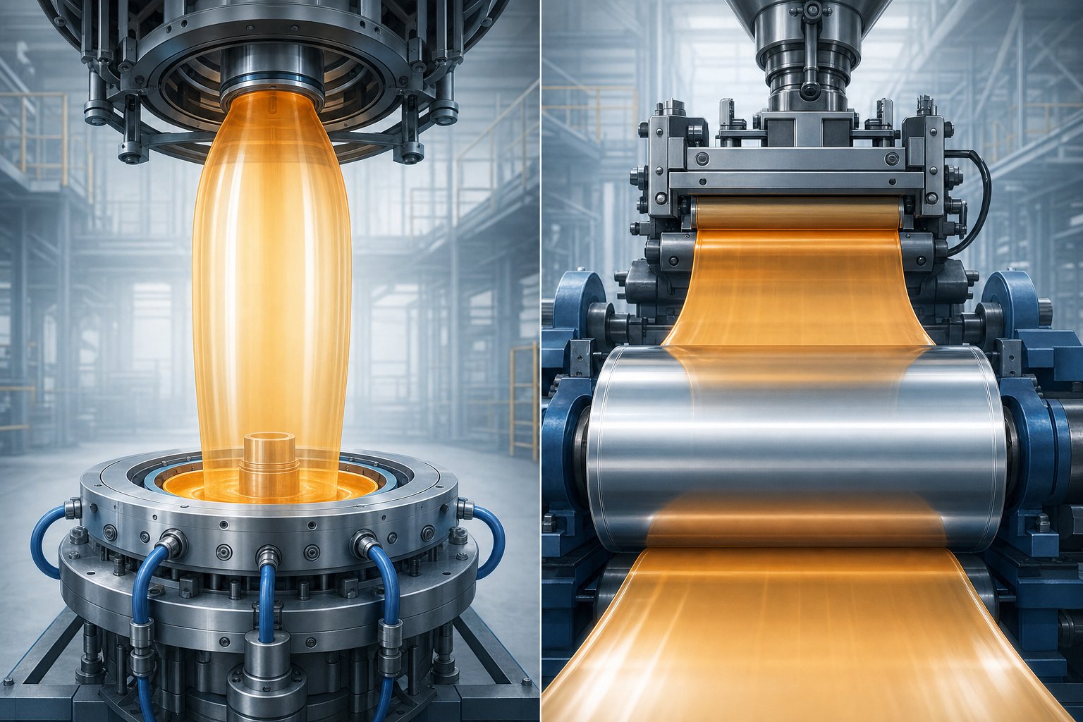
In blown film extrusion, the melt exits an annular die vertically and is inflated by internal air pressure into a large tubular bubble. An air ring cools the outer surface while the bubble rises, and the frost line marks where solidification occurs. The bubble is then collapsed flat, pulled through nip rollers, and wound into rolls. Because the bubble expands outward and is simultaneously drawn upward, the film receives biaxial orientation - stretching in both the transverse direction (TD) and the machine direction (MD).
A cast film extrusion machine operates on a different principle entirely. The melt is pushed through a flat slot die - a completely different cast film extrusion die type - and immediately pressed onto a high-speed, internally cooled chill roll. That near-instant quenching locks the polymer chains before significant crystallization can occur, producing a film with outstanding optical clarity and a glossy, glass-smooth surface. However, the stretching happens almost exclusively in MD as the chill roll draws the melt away from the die lip, leaving the film with predominantly unidirectional orientation.
These divergent cooling and orientation mechanisms are responsible for nearly every property difference you will see between the two film types. Slower air cooling in the blown process allows more crystallinity to develop, boosting toughness and barrier performance but introducing slight haze. Rapid chill-roll quenching in cast film extrusion suppresses crystallinity, delivering superior transparency at the expense of balanced strength.
When to Choose Blown Film Over Cast Film
Deciding between the two methods is rarely about one being universally "better." It comes down to which performance attributes your application demands most. The table below maps the key trade-offs side by side so you can match process strengths to your specific requirements.
| Criterion | Blown Film | Cast Film |
|---|---|---|
| Mechanical Properties (Tear and Puncture) | Superior - biaxial orientation distributes strength evenly in MD and TD | Lower tear resistance, especially in TD, due to unidirectional orientation |
| Optical Clarity and Gloss | Moderate - slower cooling increases haze | Excellent - rapid quenching preserves transparency and high gloss |
| Gauge Uniformity | Good with modern auto-profile control; slight variation possible across bubble circumference | Very tight tolerance due to flat die and chill-roll contact |
| Equipment Cost | Generally lower capital investment for comparable output widths | Higher - chill rolls, flat dies, and ancillary systems add cost |
| Width Flexibility | High - adjust blow-up ratio to change layflat width without hardware changes | Limited - width is fixed by die and chill-roll dimensions |
| Barrier Properties | Enhanced by biaxial orientation and higher crystallinity | Moderate - lower crystallinity reduces gas-barrier performance |
| Output Rate at Scale | Moderate - air cooling is the throughput bottleneck | Higher - chill-roll quenching removes heat faster, enabling greater line speeds |
| Printability | Good after corona treatment; slightly rougher surface | Excellent - smooth surface yields sharper graphics and vibrant color |
| Typical Applications | Heavy-duty sacks, agricultural films, shrink wrap, construction barriers, multilayer barrier packaging | Stretch wrap, food wrap with display clarity, medical films, lamination substrates, adhesive tapes |
A few patterns stand out. If your product faces rough handling, outdoor exposure, or needs strong gas-barrier performance, blown film's balanced orientation gives it a clear edge. If retail shelf appeal, high-resolution printing, or ultra-tight thickness tolerances drive your specification, a cast film extrusion machine will typically deliver better results. Many converters actually run both technologies under the same roof, routing each order to whichever line best fits the end-use requirement.
Interestingly, the gap between the two processes has narrowed in recent years. Modern automatic profile control on blown lines has significantly improved gauge uniformity, while advances in cast biaxial orientation have brought more balanced mechanical properties to cast films. Still, the fundamental physics - air-cooled tubular expansion versus chill-roll quenching - ensures that each method retains its core advantages.
Whichever process wins the comparison for a given application, one variable exerts enormous influence on the final film regardless of line type: the resin itself. The polymer grade you feed into the hopper shapes everything from melt stability and bubble behavior to the mechanical and optical properties of the finished roll.
Choosing the Right Polymer and Resin for Film Blowing
The resin you pour into the hopper does not just influence the finished film - it dictates it. Two operators can run identical blown film lines at identical settings, and if one feeds LDPE while the other feeds HDPE, the bubbles will behave differently, the frost lines will sit at different heights, and the resulting films will serve entirely different markets. Selecting the right polymer for a given application is arguably the most consequential decision in polyethylene blown film extrusion, yet it is also one of the least understood outside specialist circles.
LDPE, LLDPE, HDPE, and Their Blowing Behavior
Polyethylene dominates the film blowing landscape, but calling it a single material is misleading. The three major PE grades - LDPE, LLDPE, and HDPE - differ in molecular architecture, and those structural differences profoundly affect how each resin behaves inside the bubble.
LDPE (Low-Density Polyethylene) remains the classic polymer film extrusion resin for good reason. Its long-chain branching gives it exceptional melt strength - the ability to resist thinning and tearing while the bubble inflates. That stability means operators can push higher blow-up ratios, run wider layflats, and still maintain a rock-steady bubble. LDPE also delivers good optical clarity and excellent heat-seal performance, making it a natural fit for bread bags, shrink bundling, and general-purpose packaging films. Its density sits in the 0.910-0.925 g/cm3 range, with crystallinity typically between 40% and 55%. Blown film grades generally carry melt flow index (MFI) values between 0.2 and 2.0 g/10 min - low enough to provide the melt strength the process demands, but high enough to keep extruder torque manageable.
LLDPE (Linear Low-Density Polyethylene) has steadily gained market share because it delivers what LDPE cannot: superior tensile strength, puncture resistance, and environmental stress-crack resistance (ESCR). Those properties stem from its linear backbone with controlled short-chain branching, which allows tighter molecular packing and higher crystallinity (45-60%) than LDPE despite a similar density range. In practical terms, LLDPE enables downgauging - producing thinner film that matches or exceeds the mechanical performance of thicker LDPE film. That translates directly into material savings and lower shipping weight. Typical blown film LLDPE grades run at MFI values of 0.5 to 2.0 g/10 min. The trade-off? LLDPE's linear structure gives it lower melt strength, which can make the bubble more sensitive to instability at high blow-up ratios. Many converters blend LLDPE with a percentage of LDPE to combine the toughness of one with the bubble stability of the other.
HDPE (High-Density Polyethylene) occupies the opposite end of the spectrum. Minimal branching allows its chains to pack tightly into a highly crystalline structure (70-85%), yielding stiff, crinkly film with excellent moisture barrier properties. You have handled HDPE blown film countless times without realizing it - grocery sacks, cereal box liners, and retail merchandise bags are all classic examples. PE blown film extrusion with HDPE requires fractional-melt grades, often with MFI values as low as 0.02 to 0.35 g/10 min. These ultra-low-flow resins provide the melt strength needed to inflate and stabilize a bubble, but they demand significantly more extruder torque and higher barrel pressures than LDPE or LLDPE.
How does melt flow index shape processability across all three grades? The relationship is straightforward: lower MFI means higher molecular weight, which translates to greater melt strength and better bubble stability - but also higher viscosity and more mechanical energy required from the screw. As polymer processing data confirms, lower MFI polymers also tend to deliver better impact resistance, barrier properties, and stress-crack performance in the finished film. Conversely, higher MFI grades flow more easily and process at lower pressures, but they sacrifice melt strength and can produce weaker, less uniform bubbles. The sweet spot for any given application depends on balancing processability against end-use requirements.
Beyond Polyethylene - PP, PA, and Specialty Polymers
Polyethylene film extrusion may dominate global output, but it cannot solve every packaging challenge. When applications demand properties that PE simply cannot deliver - superior oxygen barrier, high-temperature resistance, or elastic recovery - converters turn to alternative polymer families.
Polypropylene (PP) is finding growing adoption in blown film for its excellent moisture barrier, higher stiffness, and better optical clarity compared to PE. Blown PP films appear in textile packaging, stationery wraps, and food applications where moisture protection matters more than flexibility. Processing PP on a blown line requires higher melt temperatures (typically 200-240 degrees C) and careful cooling management, because PP's narrower processing window makes bubble stability more challenging than with LDPE.
Polyamide (PA/Nylon) delivers outstanding oxygen and aroma barrier performance combined with best-in-class puncture resistance among flexible film substrates. In multilayer blown film structures, nylon typically serves as the barrier core layer, sandwiched between polyethylene skin layers that provide moisture resistance and heat-seal capability. Nylon 6 and Nylon 6,6 are the most common grades, processed at elevated temperatures (230-270 degrees C) due to their higher melting points.
EVOH (Ethylene Vinyl Alcohol) is one of the finest oxygen barrier materials available and is essential for modified atmosphere packaging (MAP) in food applications. However, EVOH is hygroscopic - it absorbs moisture, and when it does, its barrier performance degrades significantly. For this reason, EVOH is almost always co-extruded as a thin interior layer protected on both sides by moisture-resistant PE or PP layers.
Blown thermoplastic polyurethane (TPU) film represents an emerging and increasingly important specialty segment. TPU films offer exceptional elasticity, abrasion resistance, and biocompatibility, making them valuable in medical device packaging, wound dressings, textile laminates, and wearable technology applications. Processing TPU on blown film lines requires precise temperature control and careful screw design to avoid shear degradation of the polymer.
The table below maps each major resin family against its key processing parameters and film properties, giving you a practical starting point for matching materials to applications.
| Resin Family | Typical MFI Range (g/10 min) | Processing Temperature Window | Key Film Properties | Common End-Use Applications |
|---|---|---|---|---|
| LDPE | 0.2 - 2.0 | 160 - 220 °C | Excellent melt strength, good clarity, strong heat-seal, high flexibility | Bread bags, shrink wrap, general packaging, lamination films |
| LLDPE | 0.5 - 2.0 | 170 - 230 °C | Superior puncture and tear resistance, high elongation, enables downgauging | Stretch wrap, agricultural films, heavy-duty sacks, industrial liners |
| HDPE | 0.02 - 0.35 | 180 - 240 °C | High stiffness, excellent moisture barrier, high crystallinity, opaque | Grocery bags, cereal liners, retail merchandise bags, industrial wrapping |
| PP | 1.5 - 4.0 | 200 - 240 °C | Good clarity, high moisture barrier, higher stiffness than PE | Textile packaging, stationery films, food wrap, medical packaging |
| PA (Nylon) | 1.0 - 5.0 (at 235 °C / 2.16 kg) | 230 - 270 °C | Outstanding oxygen and aroma barrier, exceptional puncture resistance | Meat and cheese packaging, co-extruded barrier films, vacuum pouches |
| EVOH | 1.5 - 5.0 (at 210 °C / 2.16 kg) | 190 - 230 °C | Best-in-class oxygen barrier (when dry), transparent, moisture-sensitive | MAP food packaging, co-extruded barrier core layers, retort pouches |
| TPU | Varies widely by grade | 170 - 220 °C | High elasticity, abrasion resistance, biocompatibility, optical clarity | Medical device films, wound dressings, textile laminates, wearable tech |
Note: MFI ranges shown are representative of typical blown film grades. Exact values vary by manufacturer, grade, and test conditions. Always consult the resin supplier's technical data sheet for precise specifications.
Selecting the right resin is only half the equation, though. Even the ideal polymer will produce disappointing film if process parameters - melt temperature, blow-up ratio, cooling rate, line speed - are not tuned to match that resin's rheological behavior. The interplay between material choice and machine settings is where the real optimization happens.
How Process Parameters Shape Final Film Properties
You have picked the right resin, dialed in your extruder zones, and established a stable bubble. Everything looks good - until a customer rejects a roll for excessive haze, or a converter complains that the film splits too easily along one axis. Nine times out of ten, the root cause is not the polymer itself but how the process parameters were set around it. In the blown film extrusion process, every knob, setpoint, and air damper position leaves a fingerprint on the finished film. Understanding those cause-and-effect relationships is what separates competent operators from exceptional ones.
Temperature, Speed, and Blow-Up Ratio Effects
Imagine you are standing beside a running line and you bump the melt temperature up by 10 degrees C. What happens? The polymer becomes less viscous, flows more easily through the die, and the bubble surface appears glossier and more transparent. Clarity improves because the lower melt viscosity allows crystallites to form more slowly and with fewer light-scattering imperfections. Sounds like a free upgrade - but there is a catch. That same drop in viscosity reduces melt strength, meaning the bubble wall is weaker and more prone to sagging, breathing, or outright failure at the same blow-up ratio. On HDPE lines, which already operate with borderline melt strength, even a modest temperature overshoot can trigger instability that forces the operator to reduce output. The practical lesson: use melt temperature as a clarity lever, but always respect the stability ceiling imposed by your resin's rheology.
Blow-up ratio (BUR) is arguably the most powerful single variable an operator controls. Raising BUR stretches the bubble further in the transverse direction, increasing TD molecular orientation. The payoff shows up as more balanced tear resistance - the film becomes equally difficult to tear in both MD and TD rather than splitting easily along one axis. Industrial-scale research on HDPE/LLDPE blends found that BUR correlated strongly with both TD and MD mechanical properties, with R2 values between 0.91 and 0.94 for elongation at break and tensile strength. Increasing BUR also improves gauge uniformity around the bubble circumference because the expansion stretches out minor die-lip irregularities. However, pushing BUR beyond the stable range for your resin invites trouble - the bubble begins to oscillate, thickness variation spikes, and in extreme cases the tube tears. Most polyethylene blown film operations work within a BUR window of 1.5:1 to 4:1, but the sweet spot depends heavily on the specific resin grade and available cooling capacity.
Line speed - or haul-off rate - governs what happens in the machine direction. Pull the film faster and you increase the take-up ratio (TUR), stretching polymer chains along the direction of travel. Higher TUR boosts MD tensile strength and stiffness, but it also reduces film thickness and shortens the time the polymer spends in the cooling zone. The same industrial study demonstrated that TUR primarily impacts MD properties, with correlation coefficients reaching 0.90 for MD elongation at break. Shorter cooling time means less crystallization, which can reduce barrier performance and stiffness while slightly improving optical clarity. Pushing line speed is one of the defining features of high output thin film blowing machine configurations, but every speed increase must be matched with proportionally greater cooling capacity, or film quality degrades.
Air Ring Settings, Frost Line Height, and Gauge Control
If BUR and line speed control how much the film stretches, the air ring controls how fast it solidifies - and that cooling rate has a surprisingly large influence on the final product. The air ring directs a curtain of cooling air against the outer surface of the newly extruded bubble. Three variables matter most: air velocity, air temperature, and the shape of the airflow profile hitting the bubble.
Increase air ring velocity and the bubble cools faster. The frost line drops closer to the die because the polymer reaches its solidification temperature sooner. A lower frost line generally means less time for crystallites to grow, producing a film with lower crystallinity, reduced haze, and better optical clarity - ideal for retail packaging where shelf appeal matters. Decrease air velocity and the frost line rises. The polymer stays molten longer, giving crystals more time to develop. The result is a stiffer, more opaque film with improved moisture barrier properties - exactly what you want for HDPE grocery sacks or agricultural mulch films.
This relationship between frost line height and film properties works like a dial between two extremes. Too high and the inflation happens entirely in the liquid state - the film behaves almost like cast film, with minimal TD orientation. Too low and inflation occurs in a semi-solid, highly elastic state, creating excessive TD orientation that can make the film prone to MD splitting. Experienced operators target a frost line height that balances crystallinity, orientation, and optical properties for the specific product being run.
Beyond velocity, uniform air distribution around the full 360-degree circumference of the bubble is critical for gauge consistency. Even a small dead spot - caused by a blocked air ring slot, an improperly seated lip, or turbulent airflow from nearby equipment - creates a localized hot zone on the bubble. That hot zone solidifies later, stretches more, and produces a thin band in the finished film. As gauge control specialists note, cooling-related thickness variations are among the most common and costly problems in plastic film extrusion, because they force manufacturers to increase average film weight to protect against thin spots - wasting resin and cutting into margins.
Modern blown film machine automation addresses this challenge through automatic profile control (APC) systems. These closed-loop systems use a downstream thickness sensor - typically a capacitance or infrared gauge scanner - to continuously map the film's cross-direction thickness profile. That data feeds back to actuators on the die or air ring. In heater-based APC systems, segmented heating elements around the die circumference locally adjust melt viscosity to even out thick and thin spots. In airflow-based systems - also known as External Gauge Control (EGC) - arrays of individually adjustable air fingers modify cooling intensity at each circumferential position, correcting the profile much closer to where thickness is actually established: the frost line. Airflow-based systems typically offer faster response times because they act directly on the cooling environment rather than waiting for die-steel temperatures to change.
The interaction between all these variables can feel overwhelming at first, but it follows a logical structure. The table below maps each major process parameter to its primary effects on the finished film, giving you a quick reference for troubleshooting and optimization during blow film extrusion runs.
| Process Parameter | Direction of Change | Clarity | Mechanical Strength | Barrier Properties | Thickness Uniformity | Output Rate |
|---|---|---|---|---|---|---|
| Melt Temperature | Increase | Improves (lower haze) | Decreases (lower melt strength, less orientation) | May decrease (lower crystallinity) | Minimal direct effect | Slight increase (lower viscosity) |
| Blow-Up Ratio (BUR) | Increase | Slight improvement | Increases TD strength; improves MD/TD balance | Improves (higher TD orientation) | Improves (stretches out die-lip variation) | Neutral (same mass output) |
| Draw-Down Ratio (DDR) | Increase | Slight improvement | Increases MD strength; may reduce TD toughness | Variable | Can worsen if cooling is insufficient | Increases (faster haul-off) |
| Line Speed | Increase | Slight improvement (less crystallization time) | Increases MD orientation | May decrease (less crystallinity) | Can worsen without added cooling | Directly increases |
| Air Ring Velocity | Increase | Improves (lower frost line, finer crystals) | Moderate decrease in stiffness | Decreases (lower crystallinity) | Improves if airflow is uniform | Enables higher throughput |
| Frost Line Height | Increase (higher) | Decreases (more haze, larger crystals) | Increases stiffness and dart impact | Improves (higher crystallinity) | Depends on bubble stability | Limits throughput if cooling-constrained |
A couple of patterns jump out from this table. Clarity and barrier performance often move in opposite directions - the conditions that produce clear, glossy film (fast cooling, low crystallinity) tend to weaken moisture and gas barrier properties. Similarly, boosting output rate by increasing line speed or air ring velocity without rebalancing other parameters can erode mechanical performance. The best operators treat these variables as an interconnected system rather than isolated dials, adjusting two or three in concert to hit the target specification without sacrificing other properties.
One final insight worth emphasizing: as production demands grow more complex - thinner gauges, tighter tolerances, recycled content blended in - the margin for error on every parameter shrinks. That reality is driving rapid adoption of automated profile control and real-time monitoring systems that can react faster and more consistently than any human operator. Still, automation corrects deviations; it does not design the process. Understanding why each parameter moves the needle remains the foundation of every successful blown film operation.
Of course, optimizing a single layer of film is only part of the modern picture. Most high-performance packaging structures today combine multiple polymer layers in a single film, each contributing a specific function. Achieving that multilayer architecture requires a fundamentally different die design and extrusion setup - a topic that reshapes the entire equipment discussion.
Multilayer Co-Extrusion and Die Configurations Explained
A single polymer layer can only do so much. It can seal, or it can block oxygen, or it can resist puncture - but asking one material to do all three at once is like asking a single ingredient to make an entire meal. That limitation is exactly why the industry moved beyond monolayer structures decades ago. Today, multilayer co-extrusion is the dominant practice across modern blown film lines, and understanding how it works - and which die architecture suits which application - is essential for anyone specifying or operating this equipment.
From Monolayer to Multilayer - Why the Industry Evolved
Early film blowing was exclusively monolayer. A single extruder fed a single resin through a single die, and the resulting film had whatever properties that one polymer could deliver. For basic applications - simple bags, drop cloths, agricultural ground covers - monolayer LDPE or HDPE film worked perfectly well. But as packaging performance demands escalated through the 1970s and 1980s, converters hit a wall. Food brands wanted longer shelf life, which required oxygen barriers that polyethylene simply could not provide. Medical device companies needed films that combined puncture resistance with sterile peel-seal capability. Industrial users demanded structures that resisted chemical permeation while remaining flexible enough for form-fill-seal machinery.
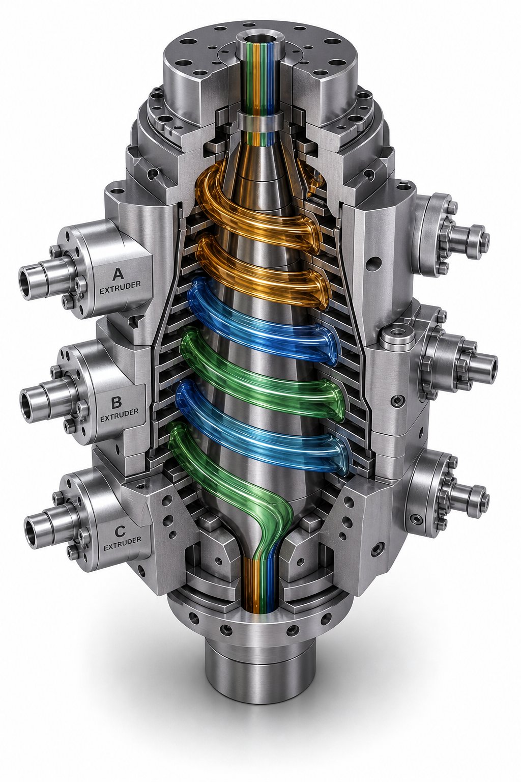
The solution was to stop asking one layer to do everything and instead assign each function to a dedicated layer within a single film structure. Co-extrusion makes this possible by running multiple extruders simultaneously, each melting a different polymer and feeding it into a shared die where the separate melt streams merge into concentric layers just before exiting the die lip. The result is a unified film in which every layer serves a specific purpose:
- Skin layers (outermost) - Provide heat-seal capability on the inner surface and printability or abrasion resistance on the outer surface. Typically made from LDPE, LLDPE, or metallocene PE.
- Core layers - Deliver the primary functional performance, whether that is oxygen barrier (EVOH or PA/nylon), moisture barrier (HDPE or PP), or structural stiffness. The core is the engineering heart of the film.
- Tie layers - Serve as molecular glue between chemically incompatible polymers. Polyethylene and nylon, for instance, will not bond to each other without a maleic anhydride-grafted tie resin bridging the interface. Without tie layers, the structure delaminates under stress.
This layered approach opened the door to structures with 3, 5, 7, or even 11 distinct layers. A typical 5-layer barrier film might follow a ratio of 15:10:40:10:15 - thin tie layers flanking a thick barrier core, with polyethylene skins on both outer surfaces. A 3-layer ABA structure, by contrast, uses matching outer layers around a different core material, simplifying recycling because the dominant polymer remains consistent throughout.
The practical impact is enormous. Every multilayer blown film machine on a modern packaging line exists because no single resin can simultaneously deliver seal integrity, gas barrier, puncture resistance, printability, and cost efficiency. Co-extrusion solves that impossible equation by letting each layer specialize.
Die Configurations for Multilayer Film
If the extruders are the muscles of a co-extrusion line, the die is its brain - the component that must merge three, five, or seven separate melt streams into a perfectly concentric, defect-free tubular structure. How the die accomplishes that task depends on its internal architecture. Three main die designs dominate multilayer blown film machinery, and each brings distinct advantages and trade-offs.
Spiral Mandrel Dies
The spiral mandrel die is the modern industry standard for most blown film machines producing multilayer structures. Inside the die body, each polymer layer enters its own set of helical channels machined into the mandrel surface. These overlapping spirals gradually thin out as they wrap around the circumference, forcing the melt to spread into a uniform annular flow before reaching the die lip.
- Advantages: Excellent melt distribution with minimal thickness variation. Virtually eliminates weld lines because the spiral overlap blends flow fronts smoothly. Handles a wide range of polymers and viscosities. Proven track record across 3-layer through 11-layer configurations.
- Limitations: Complex to manufacture, resulting in higher die cost. Cleaning and maintenance require more time due to intricate internal channel geometry. Changeover between significantly different layer configurations may require a different die altogether.
Stackable (Modular) Dies
Stackable dies - sometimes called modular or disc-type dies - build the multilayer structure by stacking individual die modules vertically, one on top of another. Each module handles a single layer, and the melt streams combine progressively as they flow upward through the stack. Need to add a layer? Bolt on another module. Need to remove one? Unbolt it.
- Advantages: Exceptional flexibility for changing layer counts without purchasing an entirely new die. Easier to disassemble for cleaning and maintenance. Individual modules can be replaced or upgraded independently, reducing long-term capital exposure.
- Limitations: The stacked arrangement creates a taller die assembly, which can complicate tower geometry and increase the distance between the extruder discharge and the die lip. Layer distribution uniformity may not match the best spiral mandrel designs, particularly at very high layer counts. Interfaces between modules can introduce subtle flow disturbances if tolerances are not tightly held.
Pancake (Flat-Stack) Dies
Pancake dies arrange each layer's distribution channel in a flat, radial disc rather than a helical spiral. The discs stack horizontally (hence the "pancake" nickname), and each one spreads its polymer outward from a central feed point to form an annular flow. This design has been around for decades and remains popular for lower-layer-count applications where cost sensitivity is high.
- Advantages: Compact design with a smaller vertical footprint than stacked modular dies. Lower manufacturing cost compared to precision-machined spiral mandrel tooling. Straightforward flow path makes cleaning relatively simple.
- Limitations: Prone to weld-line issues where the radial flow front reunites on the opposite side of the disc from the feed point. This weld line can appear as a visible streak or a localized weak spot in the finished film. Layer uniformity is generally inferior to spiral mandrel designs, especially with high-viscosity or shear-sensitive polymers.
Which architecture fits best? For high-volume, high-layer-count production lines running premium barrier films, spiral mandrel dies remain the gold standard. Converters who need maximum flexibility - running different structures for different customers on the same line - often prefer stackable modular systems. And operations focused on simpler 2- or 3-layer films at competitive cost points find that pancake dies deliver adequate performance without the capital outlay of more complex tooling.
Regardless of die type, one principle holds universally: the die can only distribute what the extruder feeds it. If the melt arriving from any extruder carries temperature inconsistencies, pressure surges, or unmelted particles, even the most sophisticated spiral mandrel die will reproduce those defects as layer-thickness variation, gels, or interfacial instability in the finished film. That dependency puts the spotlight squarely on the component responsible for melt quality in the first place - the single screw barrel at the heart of every extruder on the line.
Why the Single Screw Barrel Is the Heart of Every Film Line
A multilayer die can have the most elegant spiral mandrel geometry money can buy, but it cannot fix what arrives at its inlet. Every defect in the finished film - gauge bands, gels, haze spikes, poor seal integrity - can often be traced back to inconsistencies in the melt delivered by the extruder. And inside every blown film extruder, one component bears more responsibility for melt quality than any other: the screw and barrel assembly. Think of it this way - the die shapes the film, but the barrel and screw create the melt that makes the film possible.
Why the Screw and Barrel Are Critical to Film Quality
The single-screw extruder on a film blowing extruder machine must accomplish three demanding tasks simultaneously, without interruption, for hours or days at a stretch:
- Convey and compress - Solid pellets enter the feed zone and must be moved forward reliably while being compacted against the barrel wall to begin the melting process.
- Melt through shear and conducted heat - In the compression zone, the decreasing channel depth forces the polymer against heated barrel surfaces. The combination of frictional shear from screw rotation and conducted heat from barrel heater bands transforms solid granules into a viscous fluid.
- Meter at uniform pressure and temperature - The shallow metering zone delivers the fully molten polymer to the die at a steady, predictable flow rate. Any pressure surge or thermal inconsistency here propagates directly into the film as a thickness band, a clarity defect, or a weak spot.
That three-part sequence sounds straightforward, but the tolerances involved are unforgiving. The radial clearance between the screw flight outer diameter (O.D.) and the barrel inner diameter (I.D.) is typically just a few hundredths of a millimeter on a new film extruder. As Plastics Technology explains, when that clearance increases through wear, leakage flow over the flights becomes inevitable. The operator sees declining throughput, rising melt temperature, and increased energy consumption as the screw struggles to maintain pumping pressure. Worse, the resin leaking backward over worn flights experiences excessive shear, raising its temperature beyond the intended setpoint and potentially causing thermal degradation - visible in the film as black specks, gels, or discolored streaks.
What accelerates this wear? Several mechanisms work against barrel and screw surfaces in a typical blown film extruder machine:
- Abrasive fillers - Calcium carbonate, talc, titanium dioxide, and glass fibers act like fine sandpaper against the screw flights and barrel bore. Even at modest filler loadings, the abrasion concentrates in high-pressure zones - the compression section and the last few turns of metering - where increased pressure and temperature amplify friction.
- Corrosive polymers - PVC processing generates hydrochloric acid at elevated temperatures, aggressively attacking unprotected steel surfaces. Flame-retardant compounds and certain recycled feedstocks can release similarly corrosive byproducts.
- High-shear degradation - Running at excessive screw speeds or with resins near their thermal limits breaks down both the polymer and the barrel surface over time. Root wear on the forwarding side of the flights is a telltale symptom, creating pockets where material hangs up and degrades into contamination.
The consequences compound. A worn barrel with enlarged bore diameter reduces the extruder's ability to build pressure, which lowers output. The operator compensates by increasing screw speed, which generates more shear heat, which accelerates further wear. Industry data suggests that a flight clearance roughly four times the original tolerance is commonly used as a replacement threshold - but as screw wear specialists note, the actual impact depends heavily on resin viscosity. A higher-viscosity polyethylene suffers less rate loss at a given clearance than a lower-viscosity polypropylene under identical conditions. Waiting until performance visibly deteriorates often means the wear has already progressed well past the economically optimal replacement point.
Selecting a Reliable Single Screw Barrel for Film Extrusion
When it is time to replace or upgrade a barrel, the specification decisions you make directly determine how long the next barrel lasts and how consistent your film quality remains across the production campaign. Three factors matter most.
Metallurgy and surface treatment. Not every barrel treatment suits every application. For clean, unfilled polyethylene - the bread and butter of most blown film extruders - a nitrided barrel in a steel like 38CrMoAlA provides a hard surface case of roughly 0.4 to 0.7 mm at a cost-effective price point. As bimetallic vs. nitrided comparison data confirms, nitriding handles moderate sliding wear well and is perfectly adequate when the resin is non-abrasive. When the feedstock introduces abrasive fillers, mineral reinforcements, or recycled content with contaminants, a bimetallic barrel becomes essential. Bimetallic construction adds a centrifugally cast alloy lining - typically 2.0 to 3.0 mm thick - inside the bore, providing dramatically longer service life against abrasion and corrosion. For the most demanding duties, such as heavily glass-filled compounds or high-temperature engineering polymers, tungsten-carbide-lined barrels offer the ultimate wear resistance, though at a premium cost.
L/D ratio. The length-to-diameter ratio of the barrel determines how much working length the screw has to melt, mix, and homogenize the polymer. Film-grade applications generally demand L/D ratios of 28:1 to 33:1 - longer than many injection molding barrels - because producing a perfectly uniform, gel-free melt for thin-film applications requires extended residence time in the metering zone. Shorter barrels may save space and cost, but they risk delivering an under-homogenized melt that shows up as optical defects or mechanical weak points in the finished film.
Bore tolerance. Tight bore tolerances are non-negotiable for film extrusion. The clearance between screw flight and barrel bore controls leakage flow, shear uniformity, and ultimately the temperature consistency of the melt. Even small deviations from specification - a few hundredths of a millimeter - can create localized hot spots where resin degrades or cold zones where melting is incomplete. Reputable film extruder suppliers understand that bore straightness and roundness are just as important as surface hardness, because a perfectly hard barrel with a crooked bore still produces inconsistent film.
For operators evaluating their sourcing options, NANHAIYA's single screw barrel solution is worth considering. Engineered for plastic extrusion plants running film, pipe, sheet, pelletizing, and recycling lines, their barrels address the core requirements film processors care about most: consistent bore tolerances, appropriate metallurgical options for different resin families, and compatibility with a wide range of extruder OEM geometries. For plants that run multiple resin types - especially those blending virgin PE with post-consumer recycled content - having a barrel supplier that understands the wear profiles specific to film extrusion can mean the difference between predictable production campaigns and unplanned shutdowns for emergency replacements.
Ultimately, the screw and barrel are consumable components. They wear, they degrade, and they eventually need replacement. The question is never whether you will replace them, but whether you replace them proactively - on your schedule, with properly specified parts from a reliable source - or reactively, after quality has already suffered and scrap rates have climbed. That distinction between proactive and reactive maintenance does not apply only to barrels, of course. It extends across the entire blown film line, from die lips to air rings to nip rollers - and increasingly, it intersects with the sustainability pressures reshaping how the industry thinks about film design itself.
Maintenance Best Practices and Sustainability in Blown Film Manufacturing
Proactive maintenance and reactive maintenance produce the same invoices eventually - the difference is that one comes with a planned shutdown and a fresh roll of in-spec film on the other side, while the other arrives as a 3 a.m. phone call, a scrapped production run, and an angry customer. In industrial blown film operations, where lines often run 24/7 across multi-week campaigns, the cost gap between these two approaches is staggering. And as the industry pivots toward thinner gauges, recycled feedstocks, and mono-material structures, the margin for mechanical neglect shrinks further with every passing year.
Preventive Maintenance That Protects Film Quality
Every component on a blown film line degrades over time. Screws wear, die lips accumulate carbonized buildup, air ring slots clog with dust, and nip roller surfaces lose their grip. The goal of a preventive maintenance program is not to eliminate wear - that is impossible - but to detect it early enough to schedule corrections before quality or uptime suffers. A structured approach, broken into daily, weekly, monthly, and quarterly intervals, keeps the entire equipment train performing within specification.
The following checklist prioritizes tasks by their impact on film quality and line reliability. Adapt the intervals to your specific resin portfolio, operating hours, and environmental conditions, but treat the sequence as a baseline that covers the most failure-prone areas first.
- Daily: Inspect film output for visual defects - Check for gauge bands, gels, haze variation, wrinkles, and edge curl. These symptoms are your earliest warning system. A new defect pattern almost always points to a component drifting out of tolerance somewhere upstream.
- Daily: Verify temperature, pressure, and speed setpoints - Confirm that barrel zone temperatures, melt pressure at the die adapter, and haul-off speed match the recipe. Even small drifts - a thermocouple reading 5 degrees C higher than yesterday - deserve investigation before they cascade.
- Weekly: Clean air ring slots and check airflow uniformity - Dust, polymer fines, and ambient debris accumulate in air ring channels, creating localized cooling dead spots that directly produce thickness variation and bubble instability. Wipe down all air passages and verify that airflow feels uniform around the full circumference.
- Weekly: Inspect nip roller surfaces and alignment - Worn, glazed, or misaligned nip rollers create uneven pressure across the layflat, causing tracking problems, wrinkles, and inconsistent tension at the winder. Check rubber hardness, surface condition, and parallelism.
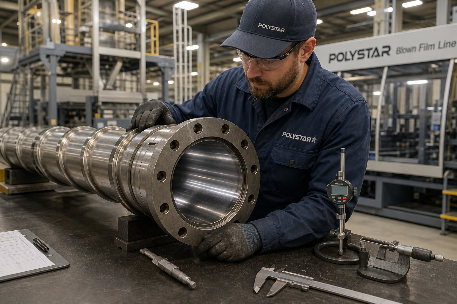
- Monthly: Measure screw and barrel wear - Use bore gauges and screw micrometers to track the clearance between flight O.D. and barrel I.D. Trending this data over time reveals wear rate patterns that let you predict replacement windows months in advance rather than reacting to sudden output drops.
- Monthly: Inspect and calibrate IBC system - Leak-test internal bubble cooling supply and exhaust lines. Even a minor air leak alters bubble pressure, destabilizing the bubble diameter and skewing gauge uniformity. Verify that IBC airflow sensors and control valves respond correctly to setpoint changes.
- Quarterly: Strip and clean die components - Remove the die, disassemble it, and clean all flow channels, lips, and mandrel surfaces of carbonized polymer residue. Inspect die lip surfaces for nicks, scratches, or corrosion that would imprint lines into the film. As maintenance specialists emphasize, fully stripping and cleaning the die and screen changer on a regular schedule prevents gradual buildup from reaching the point where it causes persistent film defects.
- Quarterly: Calibrate thickness sensors and APC systems - Automatic profile control is only as good as the sensor data feeding it. Verify sensor accuracy against a known-thickness standard and confirm that die bolt actuators or air-ring fingers respond proportionally to control signals.
- Annually: Full mechanical audit - Inspect gearbox oil, drive belts, chain tensioners, electrical connections, and safety interlocks. Conduct thermal imaging on motors, heater bands, and bearings to identify overheating components before they fail. Review machine performance logs to detect long-term degradation trends.
Among all these tasks, screw and barrel condition monitoring deserves special emphasis for blown film manufacturing. A worn barrel does not fail suddenly - it degrades gradually, stealing output rate, inflating energy costs, and quietly widening the gauge tolerance band on every roll produced. By the time an operator notices reduced throughput, the wear has typically progressed well past the point where it began affecting film quality. Proactive replacement from a dependable supplier - such as NANHAIYA's single screw barrel solutions, engineered for film, pipe, sheet, and recycling extrusion lines - prevents that slow decline from ever reaching the customer. Scheduling barrel changes during planned maintenance windows, based on measured wear data rather than guesswork, keeps blown film extrusion maintenance predictable and protects gauge consistency across extended production campaigns.
Sustainability Trends Shaping Blown Film's Future
While maintenance keeps today's lines running, three converging sustainability drivers are fundamentally reshaping what those lines will need to produce tomorrow. Each trend demands more from the extrusion equipment - tighter tolerances, broader material flexibility, and greater process control - making preventive maintenance and component quality more critical than ever.
Mono-material recyclable structures. The recycling challenge for flexible packaging has always been material complexity. A typical high-barrier pouch might combine PE, nylon, EVOH, and adhesive tie layers - a structure that delivers outstanding shelf performance but is extremely difficult to recycle because sorting facilities cannot separate the individual polymers. The industry's response is a decisive shift toward mono-material film structures - all-PE or all-PP constructions that maintain barrier and mechanical performance while remaining compatible with existing recycling streams. Brands and regulators are accelerating this transition; the EU's Packaging and Packaging Waste Regulation (PPWR) pushes for all packaging to be recyclable by 2030, and many major brand owners have committed to similar timelines voluntarily. For blown film operators, mono-material design means co-extruding multiple PE grades - each optimized for a different function - rather than mixing incompatible polymer families. The die still runs five or seven layers, but every layer is polyethylene, simplifying end-of-life sorting without sacrificing in-use performance.
Downgauging with metallocene LLDPE. Producing thinner film that matches or exceeds the performance of thicker conventional film is one of the most impactful sustainability levers available in plastic film manufacturing. Advanced metallocene-catalyzed LLDPE resins make this possible. Their narrow molecular weight distribution and precisely controlled short-chain branching deliver exceptional dart impact, puncture resistance, and seal strength at gauges 20-30% thinner than legacy Ziegler-Natta LLDPE grades. The environmental math is straightforward: less resin per square meter means fewer fossil resources consumed, lighter shipping pallets, and lower carbon emissions across the entire supply chain. However, downgauging tightens the process window considerably. A 25-micron film has far less tolerance for gauge variation than a 40-micron film - a 2-micron thick spot that was invisible at heavier gauges becomes a functional defect on a downgauged structure. That reality demands extruder components capable of delivering exceptionally uniform melt, which circles back to barrel bore tolerance, screw condition, and die cleanliness.
Post-consumer recycled (PCR) content integration. Incorporating recycled resin into blown film structures is no longer optional for many converters - brand commitments and emerging regulations are mandating minimum PCR percentages in packaging films. The challenge is that PCR feedstock is inherently inconsistent. As Reifenhauser's engineering team notes, recycled material arrives with variable viscosity, color, contamination levels, and foreign substances that change from batch to batch. Those fluctuations stress every component in the extrusion system, but the barrel and screw absorb the worst of it. Inorganic contaminants in PCR streams - paper fibers, label adhesive residue, mineral fillers from other packaging formats - act as abrasive particles that accelerate bore wear and flight erosion far faster than virgin resin. Higher PCR percentages compound the problem, demanding highly wear-resistant screws and barrels specifically engineered to handle the abuse. Plants ramping up recycled content need to shorten their inspection intervals and budget for more frequent barrel replacements - ideally with bimetallic or alloy-lined options that match the specific wear profile of their PCR feedstock.
The future of blown film lies in producing thinner, stronger, fully recyclable structures - a goal that depends on precise extrusion control from hopper to die.
These three trends reinforce each other. Mono-material structures simplify recycling, which increases the availability of clean PCR feedstock, which enables higher recycled content in the next generation of film - closing the loop. Downgauging reduces the total volume of material entering that loop in the first place. Together, they represent the clearest trajectory the blown film manufacturing sector has seen in decades: do more with less, and make sure everything you produce can come back around again.
For plant managers and operators, the practical takeaway is clear. Maintaining the extrusion equipment that makes all of this possible is not a cost center - it is the enabling condition for competing in a market that increasingly measures success in microns saved, recycled content percentages achieved, and recyclability certifications earned. Investing in reliable barrel and screw solutions - whether through proactive replacement schedules or upgrades to more wear-resistant metallurgies from suppliers like NANHAIYA - directly supports the precision and consistency that film manufacturing demands as structures get thinner, specifications get tighter, and recycled content rises. The lines that thrive in this environment will be the ones maintained well enough to handle whatever the hopper delivers, campaign after campaign.
Frequently Asked Questions About Film Blowing
1. What is the difference between blown film and cast film extrusion?
Blown film extrusion inflates molten polymer into a vertical tubular bubble using internal air pressure and cools it with an air ring, producing biaxially oriented film with balanced tear strength and superior puncture resistance. Cast film extrusion pushes melt through a flat slot die onto a chilled roller, yielding film with better optical clarity and tighter gauge tolerance but predominantly single-direction orientation. Blown film suits heavy-duty sacks, barrier packaging, and agricultural covers, while cast film excels in stretch wrap, display-quality food wrap, and lamination substrates.
2. What is blow-up ratio in blown film extrusion and why does it matter?
Blow-up ratio (BUR) is the ratio of the inflated bubble diameter to the annular die diameter. For example, a 200 mm die producing a 600 mm bubble has a BUR of 3:1. Typical industrial values range from 1.5:1 to 4:1. BUR directly controls transverse-direction molecular orientation, which determines balanced tear resistance, thickness uniformity around the bubble, and barrier performance. Combined with the draw-down ratio governing machine-direction stretching, BUR creates the biaxial orientation that gives blown film its signature mechanical advantages over cast film.
3. Which polymers are commonly used in film blowing?
LDPE is the classic choice, offering excellent melt strength and bubble stability for general packaging. LLDPE delivers superior puncture and tear resistance, enabling thinner films that match heavier-gauge performance. HDPE produces stiff, high-barrier film for grocery bags and cereal liners. Beyond polyethylene, polypropylene provides moisture barrier and clarity, polyamide (nylon) adds oxygen barrier capability in multilayer structures, EVOH serves as a gas-barrier core layer, and thermoplastic polyurethane (TPU) addresses medical and textile specialty applications. Each resin requires specific melt temperature, MFI range, and screw-barrel configuration for optimal processing.
4. How does the single screw barrel affect blown film quality?
The single screw barrel is responsible for melting, compressing, and metering polymer at uniform pressure and temperature. Any wear in the barrel bore increases flight-to-wall clearance, causing leakage flow, inconsistent melt temperature, pressure surges, and ultimately gauge bands, gels, or haze defects in the finished film. Barrel metallurgy matters: nitrided barrels suit clean polyethylene, bimetallic barrels handle abrasive fillers and recycled content, and tungsten-carbide linings serve the most demanding compounds. Suppliers like NANHAIYA offer single screw barrel solutions at nhyscrews.com engineered for film extrusion plants requiring tight bore tolerances and long service life.
5. What maintenance tasks are most important for blown film extrusion lines?
Priority maintenance includes daily visual inspection of film for gauge bands and gels, weekly air ring cleaning and nip roller alignment checks, monthly screw-barrel wear measurement using bore gauges, monthly IBC system leak testing, and quarterly die strip-down with full flow-channel cleaning. Tracking barrel wear data over time allows operators to schedule proactive replacements before quality deteriorates, avoiding unplanned downtime. Plants processing recycled content or filled compounds should shorten inspection intervals because abrasive contaminants accelerate bore wear significantly faster than virgin resin.
Written by
Nanhaiya Technical Team
Zhoushan Nanhaiya Plastic Machinery Co., Ltd.
The Nanhaiya technical team supports screw and barrel manufacturing projects through application review, technical communication, custom manufacturing coordination, and production and quality control.
Discuss Your Application
Related Articles
More insights on screw barrel technology and plastics processing.

What Nobody Tells You About Screw Barrel For Plastic Machine Design
Oct 10, 2026
Learn how screw barrel for plastic machine design affects melt quality, throughput, and wear life. Covers geometry, resin matching, troubleshooting, and sourcing.
Read Article
Single Screw Extruder for Sheet: Stop Guessing, Start Specifying
Oct 9, 2026
Learn how to specify a single screw extruder for sheet production. Covers screw geometry, resin-specific processing, troubleshooting, and maintenance best practices.
Read Article
PE Pipe Extruder Machine: What Datasheets Won't Tell You
Oct 9, 2026
Learn how a PE pipe extruder machine works, key specs explained, material grade selection, maintenance tips, and buyer guidance beyond the datasheet.
Read ArticleLooking for something else?
Search by material, symptom or product and jump straight to the relevant page.
These are navigation suggestions based on keyword matching — not a quotation, not a delivery commitment, and not a substitute for engineering review. Final specification is confirmed by our engineers against your drawings and processed material.
Need help with screw barrel selection?
Share your machine model, processed material and application. Our team can help with pricing and technical support.