

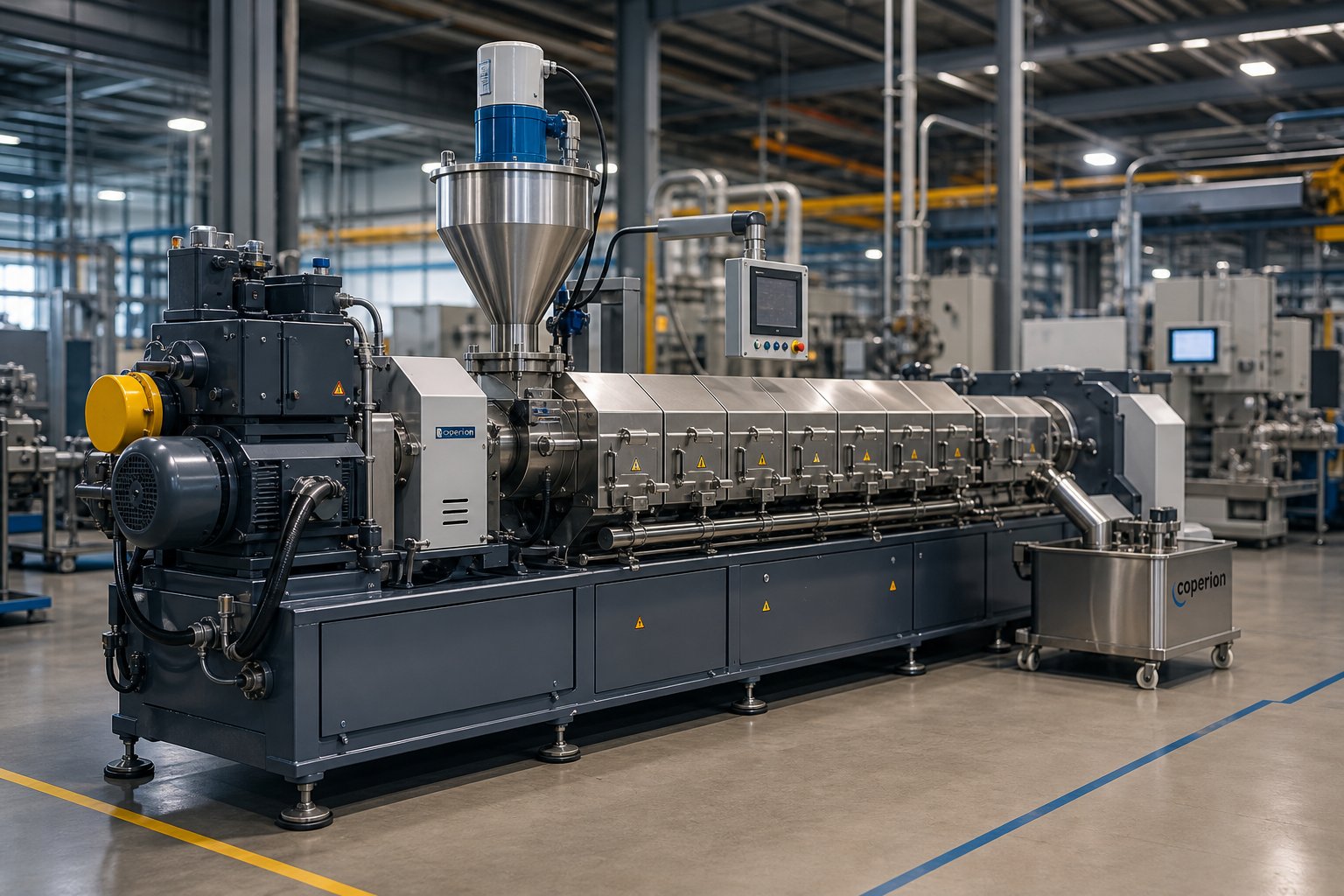
What Filler Masterbatch Is and Why Twin Screw Extruders Are the Standard
Whether you're a plant engineer sizing up a new compounding line, a production manager chasing higher throughput, or a procurement professional comparing equipment options, the same question keeps coming up: what actually makes a filler masterbatch twin screw extruder the right choice for this application? Before diving into equipment specifics, it helps to get the fundamentals sharp.
What Is Filler Masterbatch
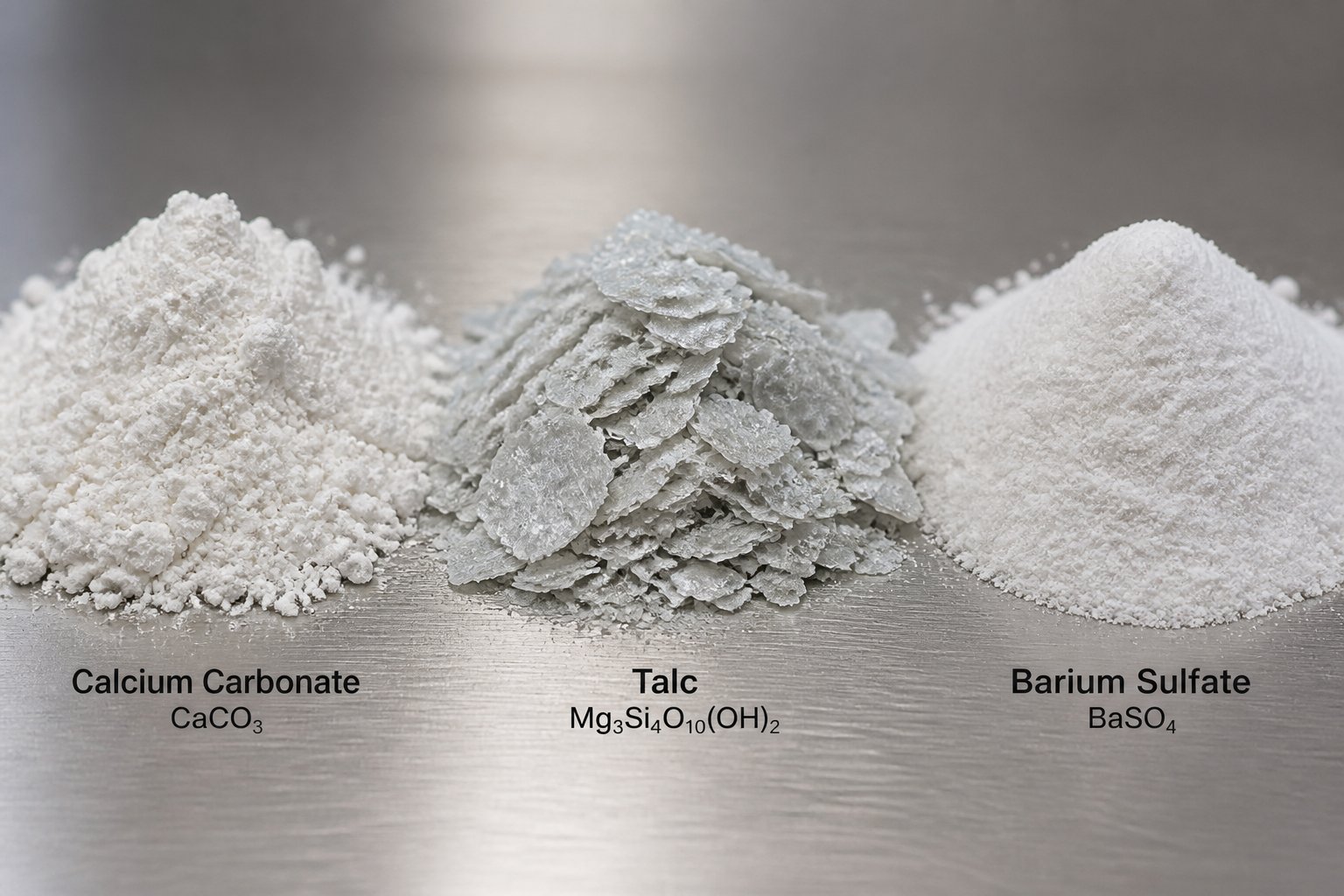
Filler masterbatch is a pelletized concentrate in which high concentrations of mineral fillers — typically calcium carbonate (CaCO3), talc, or barium sulfate (BaSO4) — are dispersed into a polymer carrier resin such as PE or PP, producing uniform pellets that downstream processors blend into their base resins during film blowing, injection molding, pipe extrusion, and other converting operations.
In practical terms, imagine taking a fine mineral powder and locking it inside tiny plastic pellets so it flows, feeds, and melts just like regular resin. That's filler masterbatch. It eliminates the dust, inconsistency, and handling headaches of raw powder while delivering cost savings and property improvements — increased stiffness, better dimensional stability, faster cooling — to finished plastic products. Filler loadings in these pellets commonly range from 50% to over 80% by weight, which means the compounding equipment doing the work faces an unusually demanding task.
Why Twin Screw Extruders Dominate Filler Compounding
A single screw machine relies on friction between material and barrel wall to convey and mix. That works fine for melting neat polymers, but it falls short when you need to incorporate massive volumes of dense mineral powder into a thin resin matrix. A co-rotating twin screw extruder solves this problem through several engineering advantages that directly impact output quality and production economics:
- Self-wiping action: The intermeshing, co-rotating screws continuously scrape material off each other's surfaces, preventing dead zones where filler agglomerates could hide and ensuring consistent residence time.
- Modular barrel and screw design: Barrel sections and individual screw elements can be rearranged to match specific filler types, loading levels, and carrier resins — a flexibility single screw machines simply cannot offer.
- Superior dispersive and distributive mixing: Kneading blocks break apart filler agglomerates (dispersive mixing), while specialized elements spread those particles evenly throughout the melt (distributive mixing). Both are critical when you're pushing filler content above 60%.
- High free volume for filler intake: The open channel volume between screws and barrel — controlled by the outer-to-inner screw diameter ratio (Do/Di) — determines how much low-bulk-density powder the extruder can swallow. Machines with a Do/Di ratio of 1.65 or higher provide the deep screw channels that highly filled compounds demand.
These characteristics explain why virtually every serious filler masterbatch extruder on the market today is a co-rotating twin screw design. The technology doesn't just outperform single screw alternatives — it makes high-filler compounding commercially viable in the first place. Still, choosing the right machine is only the beginning. The real performance gains — and the pitfalls most suppliers won't mention — live in the details of how raw materials are prepared and fed into that extruder.
The Complete Filler Masterbatch Production Workflow Step by Step
Every filler masterbatch pellet you hold in your hand passed through a carefully sequenced chain of operations — and each stage exists for a specific engineering reason. Skip one, cut corners on another, and you'll see it in the final product: poor dispersion, inconsistent loading, porous strands, or pellets that crumble before they reach the converting line. Here's the full nine-step workflow that a filler masterbatch extruding machine and its supporting equipment must execute, along with the "why" behind each stage.
Raw Material Preparation and Filler Surface Treatment
The first three steps happen before material ever touches the extruder screws — yet they determine most of the quality outcomes downstream.
- Raw material drying and pre-mixing. Mineral fillers like CaCO3 and talc readily absorb atmospheric moisture, and carrier resins can pick up surface water during storage. Even 0.1–0.2% moisture in the feed creates steam bubbles inside the melt, leading to porous strands and weak pellets. Drying filler powder to below 0.1% moisture content — typically in hot-air dryers or fluidized bed systems — eliminates this risk. Pre-mixing the dried filler with carrier resin pellets and additives in a high-speed mixer for 5–15 minutes ensures a roughly homogeneous blend before extrusion. You'll notice that plants skipping this step almost always struggle with inconsistent pellet quality and frequent torque spikes at the extruder.
- Filler surface treatment. Raw mineral particles are hydrophilic — they attract water and repel the oily polymer melt you're trying to bond them to. Surface treatment bridges that gap. Stearic acid coating is the most common method: at 100–120 degrees Celsius in a high-speed mixer, stearic acid molecules chemically bond to the hydroxyl groups on the CaCO3 surface while their non-polar tails create compatibility with polyolefin resins. For higher-performance applications, silane coupling agents form covalent bonds between the filler surface and the polymer matrix, significantly boosting mechanical properties. Titanate coupling agents offer a third option, particularly effective when you need to push filler loading above 70% because they reduce melt viscosity and improve particle wetting. The practical impact? Properly surface-treated filler feeds more smoothly, disperses faster inside the barrel, and produces masterbatch with fewer agglomerates and better mechanical properties in the end product.
- Feeding and metering into the extruder. Accurate, consistent feeding is the heartbeat of any filler masterbatch pelletizing extruder. Carrier resin typically enters through the main hopper using a gravimetric feeder that monitors weight loss in real time — a far more precise method than simple volumetric screw feeders, especially when filler-to-resin ratios must be held within tight tolerances. At high filler loadings (above 65%), mineral powder is often introduced through a downstream side feeder rather than the main hopper. Why? Feeding all the filler at the throat would overwhelm the screws before the resin has melted, causing torque overloads and poor wetting. Side feeding lets the resin melt first, then introduces filler into an already molten stream where it can be properly incorporated.
Extrusion, Pelletizing, and Downstream Handling
With prepared materials flowing into the barrel at controlled rates, the twin screw extruder and its downstream equipment take over.
- Melt conveying and compounding inside the barrel. This is where the real work happens. As the co-rotating screws pull material forward, the carrier resin melts under the combined effect of barrel heaters and shear energy from kneading blocks. Simultaneously, filler particles are dispersed — agglomerates are broken apart by high-shear kneading elements and then distributed uniformly throughout the melt by specialized mixing elements. Barrel temperatures are set zone by zone: lower in the feed section to prevent premature melting that blocks powder intake, progressively higher through the melting and mixing zones (typically 160–200 degrees Celsius for PE carriers, 180–220 degrees Celsius for PP), and slightly reduced toward the die to stabilize melt pressure. Residence time inside the barrel generally runs 2–5 minutes — long enough for thorough dispersion, short enough to avoid thermal degradation of the carrier resin.
- Venting and degassing. Even with careful drying, residual moisture, trapped air, and volatile decomposition products generate gas inside the pressurized melt. A venting zone — created by reverse screw elements that build a melt seal upstream — exposes the melt to atmospheric or vacuum conditions, allowing gases to escape through open barrel ports. Without proper degassing, you get foamed or porous strands that break during pelletizing and produce weak, inconsistent granules. Plants running filler masterbatch granules extruder lines at high throughput rates often use vacuum-assisted venting to pull volatiles out more aggressively.
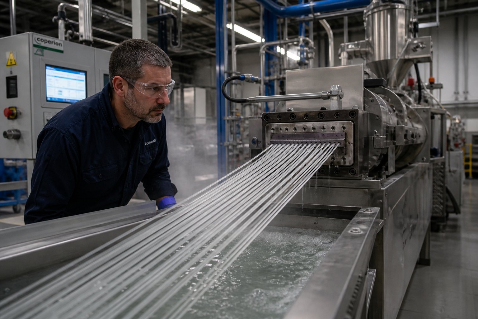
- Die extrusion and strand formation. The compounded melt exits the barrel through a die plate with multiple round holes, forming continuous spaghetti-like strands. Die hole diameter, number of holes, and land length must be matched to the melt viscosity and throughput rate. Too few holes or too-small diameters create excessive back pressure that stresses the gearbox and motor. Too many holes can reduce back pressure below the level needed for consistent flow distribution across all strands. For heavily filled compounds, larger die holes — typically 3–4 mm — are preferred because the high mineral content makes the melt less elastic and more prone to strand breakage at the die exit.
- Water bath or air cooling. Freshly extruded strands emerge at melt temperature and need rapid, controlled cooling to solidify before cutting. A water bath — a long trough of circulating cool water — is the most common approach, offering fast and uniform cooling. The water temperature and bath length determine how quickly the strands reach a cuttable state. Air cooling is an alternative for formulations sensitive to moisture pickup or when you need completely dry pellets immediately after cutting. Air-cooled systems blow chilled air across the strands using fans, though they typically require more floor space and longer cooling distances than a water bath.
- Pelletizing. Cooled, solid strands are pulled through a strand cutter — a set of rotating blades and feed rollers — that chops them into uniform cylindrical pellets, typically 2–5 mm in length. This is the most widely used method for filler masterbatch plastic pelletizing extruder lines due to its simplicity and low maintenance. Underwater pelletizers offer an alternative: they cut the melt directly at the die face while submerged in a water stream, producing round, uniform pellets with minimal dust. Underwater systems shine when you need high throughput with very consistent pellet geometry, though they add complexity and cost. The choice between strand cutting and underwater pelletizing often comes down to production volume, pellet shape requirements, and the specific filler loading — heavily filled compounds sometimes strand-cut more reliably because their reduced melt elasticity makes die-face cutting trickier to control.
- Screening, drying, and bagging. Even a well-tuned line produces occasional oversized or undersized pellets, fines, and dust — especially with high-filler formulations. A vibrating screen separates these off-spec particles, which can typically be reworked. If water-bath cooling was used, pellets pass through a centrifugal dryer or fluidized bed dryer to remove surface moisture before packaging. Finally, dried pellets are weighed by an automatic packaging system and sealed into moisture-barrier bags, usually 25 kg sacks or 1-ton bulk bags. Proper sealing matters: filler masterbatch can reabsorb moisture from humid warehouse air, and excess moisture causes processing problems when the pellets are eventually melted by the end user.
Each of these nine stages feeds into the next, and a bottleneck or quality lapse at any single point ripples through the entire line. The workflow looks straightforward on paper, but the devil lives in the details — particularly in how different filler minerals interact with the extruder's screw design, barrel metallurgy, and processing parameters.
How Different Filler Types Change Your Extruder Requirements
Here's something most equipment suppliers gloss over: not all mineral fillers behave the same way inside a twin screw barrel. The filler you choose — CaCO3, talc, or BaSO4 — fundamentally alters the demands placed on your screw profile, barrel metallurgy, feeding system, and energy consumption. Treating them as interchangeable is a fast track to premature wear, poor dispersion, and frustrating production inconsistencies. Let's break down what each filler actually does to your extruder.
CaCO3 Processing Characteristics and Extruder Demands
Calcium carbonate is by far the most widely used mineral in filler masterbatch production, and for good reason — it's abundant, inexpensive, and compatible with a broad range of carrier resins. But running a CaCO3 filler masterbatch extruder effectively means understanding the differences between its two main forms.
Ground calcium carbonate (GCC) is produced by mechanically crushing and milling limestone or marble. Typical particle sizes range from 1 to 45 micrometers, with most filler masterbatch applications using grades in the 2–10 micrometer range. GCC particles have irregular, blocky shapes and relatively low surface areas, which means they disperse with moderate mixing energy and accept stearic acid surface treatment readily.
Precipitated calcium carbonate (PCC) is synthesized chemically, producing particles as fine as 0.02–2 micrometers with much higher surface areas. That fineness delivers superior gloss and opacity in finished products — but it comes at a cost inside the extruder. Higher surface area means more polymer is needed to wet each particle, and the tendency to form stubborn agglomerates increases dramatically. A calcium carbonate filler masterbatch extruder processing PCC grades needs more aggressive kneading block configurations and often higher specific energy input compared to one running coarser GCC.
The wear dimension matters too. CaCO3 sits at 3 on the Mohs hardness scale — modest compared to glass fiber or silica, but still abrasive enough to erode standard nitrided barrels and screw elements over thousands of operating hours, especially at loadings above 70%. The finer the particle, the slower the wear rate tends to be, but the sheer volume of mineral passing through the barrel at high loading levels accumulates damage over time. Operations running a filler masterbatch CaCO3 extruder at 75%+ loading should plan for accelerated wear part replacement cycles.
Talc and BaSO4 Considerations for Screw and Barrel Design
Talc brings a completely different processing personality to the table. Its defining feature is shape — not chemistry. Talc is a hydrated magnesium silicate with a platy, lamellar structure where each particle looks like a thin disc rather than an irregular chunk. This platelet morphology is precisely what makes talc valuable in end products: the high aspect ratio (diameter-to-thickness ratio) reinforces the polymer matrix, increases stiffness, and improves dimensional stability.
The catch? Excessive shear during compounding shatters those platelets into smaller, lower-aspect-ratio fragments — destroying the very property you're paying for. A CaCO3/talc filler masterbatch extruder screw profile that works beautifully for calcium carbonate may be far too aggressive for talc. You'll want to favor gentler mixing elements — wider kneading block stagger angles and distributive mixing elements — that break up agglomerates without fracturing individual platelets.
On the positive side, talc is remarkably gentle on equipment. With a Mohs hardness of just 1, it's the softest mineral known and causes significantly less barrel and screw wear than CaCO3 or BaSO4. Its naturally hydrophobic platelet faces also mean it disperses into polymer melts more readily than most mineral fillers, often requiring less intensive surface treatment. Typical particle sizes for masterbatch-grade talc range from 1 to 15 micrometers (median), though specifying by mesh alone is misleading — two talcs passing 325 mesh can have median sizes differing by an order of magnitude.
Barium sulfate (BaSO4) introduces yet another challenge: density. With a specific gravity of roughly 4.3–4.5 g/cm³ — more than double that of CaCO3 and nearly triple that of talc — BaSO4 creates serious feeding headaches. Volumetric feeders struggle because the weight-per-screw-revolution varies wildly with material packing, making gravimetric loss-in-weight feeders essentially mandatory. Inside the barrel, the heavy particles tend to settle and segregate if conveying speeds drop, demanding consistent screw speed and carefully balanced throughput. BaSO4 also registers a Mohs hardness of 3–3.5, putting barrel wear roughly on par with CaCO3. Its primary applications — sound deadening, radiation shielding, and high-density compounds — justify the extra processing complexity, but only when the extruder is specifically configured for it.
The relationship between particle size, surface area, and extruder demands follows a clear pattern across all filler types: finer particles mean higher surface area, which demands more mixing energy to wet and disperse, increases melt viscosity, and raises specific energy consumption per kilogram of output. Coarser particles are easier to process but deliver less surface area for polymer-filler interaction, potentially compromising mechanical properties in the end product. Finding the sweet spot is always application-specific.
| Property | CaCO3 (GCC) | CaCO3 (PCC) | Talc | BaSO4 |
|---|---|---|---|---|
| Mohs Hardness | 3 | 3 | 1 | 3–3.5 |
| Typical Particle Size | 1–45 µm | 0.02–2 µm | 1–15 µm (d50) | 1–30 µm |
| Particle Shape | Irregular / blocky | Cubic / rhombohedral | Platy / lamellar | Rounded / prismatic |
| Specific Gravity | 2.7 | 2.7 | 2.7–2.8 | 4.3–4.5 |
| Surface Treatment | Stearic acid, silane, titanate | Stearic acid, silane, titanate | Often unnecessary (hydrophobic faces); silane for bonding | Stearic acid, silane |
| Relative Abrasiveness | Moderate | Low–moderate (finer particles) | Very low | Moderate–high |
| Feeding Difficulty | Low–moderate | Moderate (fine powder, bridging risk) | Moderate (low bulk density) | High (extreme density, segregation) |
| Primary End-Use Applications | Film, bags, pipes, injection molding | High-gloss film, specialty coatings | Automotive parts, rigid packaging, appliances | Sound barriers, radiation shielding, high-density compounds |
This comparison makes one thing clear: your extruder setup should never be a one-size-fits-all configuration. Every time you switch filler types — or even shift from a coarse GCC to a fine PCC grade — the screw profile, barrel wear protection, feed system, and temperature settings all deserve a second look. Yet filler selection is only half the equation. The carrier resin you pair with that filler introduces its own set of processing variables that directly affect maximum achievable loading and downstream product performance.
Carrier Resin Selection and Its Impact on Processing and Performance
Ask most equipment suppliers about carrier resin, and you'll get a vague answer: "use PE or PP." That's a bit like saying "use metal" when someone asks what grade of steel to build a bridge from. The carrier resin you choose shapes everything — your barrel temperature profile, screw speed window, maximum filler loading, pellet integrity, and how the masterbatch ultimately performs when a converter melts it into their end product. Yet this topic is almost entirely absent from technical literature on filler masterbatch extrusion equipment. Let's fix that.
PE, PP, and EVA as Carrier Resins
The carrier resin has two jobs inside the extruder: melt early enough to wet the incoming filler particles, and form a continuous matrix that holds those particles in place after pelletizing. Different resins accomplish those jobs under very different conditions, and your customized PE PP filler masterbatch extruder setup needs to reflect those differences.
- LDPE (Low-Density Polyethylene): The workhorse carrier for CaCO3 masterbatch. Its long-chain branching gives it a relatively low melt viscosity at processing temperatures of 150–190 degrees Celsius, meaning it flows easily around filler particles and wets them quickly. LDPE accepts high filler loadings (up to 80%+) without creating excessive torque on the extruder motor. Best suited for blown film, shopping bags, and general packaging applications where the end product also uses PE resin. The downside? Its branched structure means lower melt strength compared to LLDPE, which can cause strand instability at the die exit in some formulations.
- LLDPE (Linear Low-Density Polyethylene): Increasingly favored over LDPE as a carrier — and for good reason. Under the same melt flow rate, LLDPE delivers higher melt viscosity than LDPE due to its linear molecular structure with short-chain branches. That higher viscosity generates greater shear forces during compounding, which actually improves filler dispersion. LLDPE also provides better mechanical properties in the final masterbatch pellet, reducing breakage during handling and pneumatic conveying. Typical processing temperatures mirror LDPE (150–190 degrees Celsius). Ideal for film and flexible packaging where both cost savings and end-product toughness matter.
- HDPE (High-Density Polyethylene): Used as a carrier when the downstream product is itself HDPE — pipes, containers, blow-molded drums. Its higher crystallinity and melting point (around 130 degrees Celsius versus 110 degrees Celsius for LDPE) require slightly elevated barrel temperatures. HDPE's stiffer melt can make filler wetting marginally harder at equivalent MFI, but it delivers excellent pellet rigidity and low moisture absorption during storage.
- PP (Polypropylene): A pp filler masterbatch compounding twin screw extruder for plastic applications demands tighter thermal control than any PE-based setup. PP melts at approximately 160–170 degrees Celsius and processes at barrel temperatures of 180–220 degrees Celsius — a narrower safe window before thermal degradation begins. PP's higher melting point means the resin takes longer to fully melt and wet the filler, so feeding sequences and kneading block placement need adjustment. The payoff is compatibility with PP-based end products such as woven bags, automotive parts, and rigid containers. One practical note: using PE-carrier masterbatch in PP end products often creates flow marks and reduced spinnability because PE and PP, despite both being polyolefins, are not fully compatible at the molecular level.
- EVA (Ethylene-Vinyl Acetate): The secret weapon for pushing filler loading higher. EVA's polar vinyl acetate groups create stronger interactions with surface-treated mineral particles, improving wetting and allowing loadings that would choke a straight PE system. Its lower crystallinity and softer, more flexible melt also reduce internal stresses during high-filler compounding. An EVA filling masterbatch extruder typically runs at 140–180 degrees Celsius — cooler than PP, which helps preserve surface treatment chemistry on the filler. EVA-carrier masterbatch is the go-to for flexible applications, breathable films, and as a blending component alongside PE-carrier grades when you need to reach 80%+ mineral content. The trade-off is cost: EVA resin prices typically run 20–40% higher than commodity PE grades.
- PS (Polystyrene): A niche carrier used when the end product is PS-based — disposable food containers, insulation foam, and certain consumer goods. PS is amorphous, so it softens gradually rather than melting sharply, which can actually ease the initial mixing phase. Processing temperatures of 180–230 degrees Celsius apply. However, PS is more susceptible to thermal degradation than polyolefins, and its rigid, brittle nature limits maximum filler loading to roughly 50–60% before pellet integrity suffers.
The golden rule, as confirmed by industry formulation principles, is to match the carrier resin to the downstream product resin whenever possible. Same resin family means guaranteed compatibility — no flow marks, no delamination, no mechanical property surprises. When exact matching isn't feasible, selecting a carrier with lower molecular weight (higher MFI) than the product resin ensures the masterbatch disperses readily during let-down.
How Carrier Resin MFI Affects Filler Loading Capacity
Melt flow index — measured in grams per 10 minutes under standardized temperature and load — is the single most important carrier resin specification for filler masterbatch production. Here's why it matters so much.
A higher MFI means lower melt viscosity, which translates to easier flow around filler particles and faster wetting. Research on polypropylene composites with different MFI values showed that PP with an MFI of 23 g/10 min achieved significantly better filler dispersion, stronger interfacial bonding, and higher mechanical property improvements compared to PP with an MFI of just 3 g/10 min — processed under identical conditions on the same twin screw extruder. The SEM images were striking: the low-MFI matrix left filler surfaces clean and poorly bonded, while the high-MFI matrix coated and adhered to particles thoroughly.
Sounds simple — just use the highest MFI resin available, right? Not so fast. There's a catch that trips up many producers. Very high MFI resins have low molecular weight, which means reduced melt strength, weaker pellets, and potentially degraded mechanical properties in the final product. If the carrier MFI is dramatically higher than the product resin's MFI, you can also get uneven color distribution and surface defects during converting.
The practical sweet spot for most CaCO3 filler masterbatch? A carrier resin MFI of 7–25 g/10 min (measured at the standard conditions for the resin type). At the lower end of that range, you get good pellet strength and mechanical integrity. At the higher end, you gain the wetting and dispersion advantages that allow filler loadings to push toward 80%. For EVA+CaCO3 filling masterbatch pelletizing extruder setups targeting ultra-high loading, EVA grades with MFI values of 15–30 g/10 min are common because the VA content already provides the polarity needed for filler wetting — you just need enough flow to let the mineral concentrate into the melt without seizing the screws.
One more interaction worth flagging: as filler loading increases, the effective MFI of the compound drops — often dramatically. A carrier resin with an MFI of 20 might produce a masterbatch with a measured MFI of just 2–5 after 75% CaCO3 is incorporated. This is normal, but it means you need to design your die, cooling, and pelletizing parameters around the final compound's flow behavior, not the neat resin's MFI. Ignoring this mismatch is one of the most common causes of die pressure instability and inconsistent pellet geometry.
Carrier resin selection sets the processing boundaries — but within those boundaries, the screw element configuration is where you fine-tune dispersion quality, throughput, and energy efficiency. That's where the real engineering artistry of twin screw compounding reveals itself.
Screw Element Configuration Principles for Filler Masterbatch
Carrier resin sets the thermal boundaries. Filler type dictates wear and dispersion targets. But the screw profile is where you actually control what happens to those materials inside the barrel — and it's the one area where most filler masterbatch extruder machine suppliers offer the least transparency. Ask for a recommended screw configuration and you'll typically receive a generic layout with no explanation of why specific elements sit where they do. That leaves plant engineers guessing, and guessing with modular screw elements gets expensive fast.
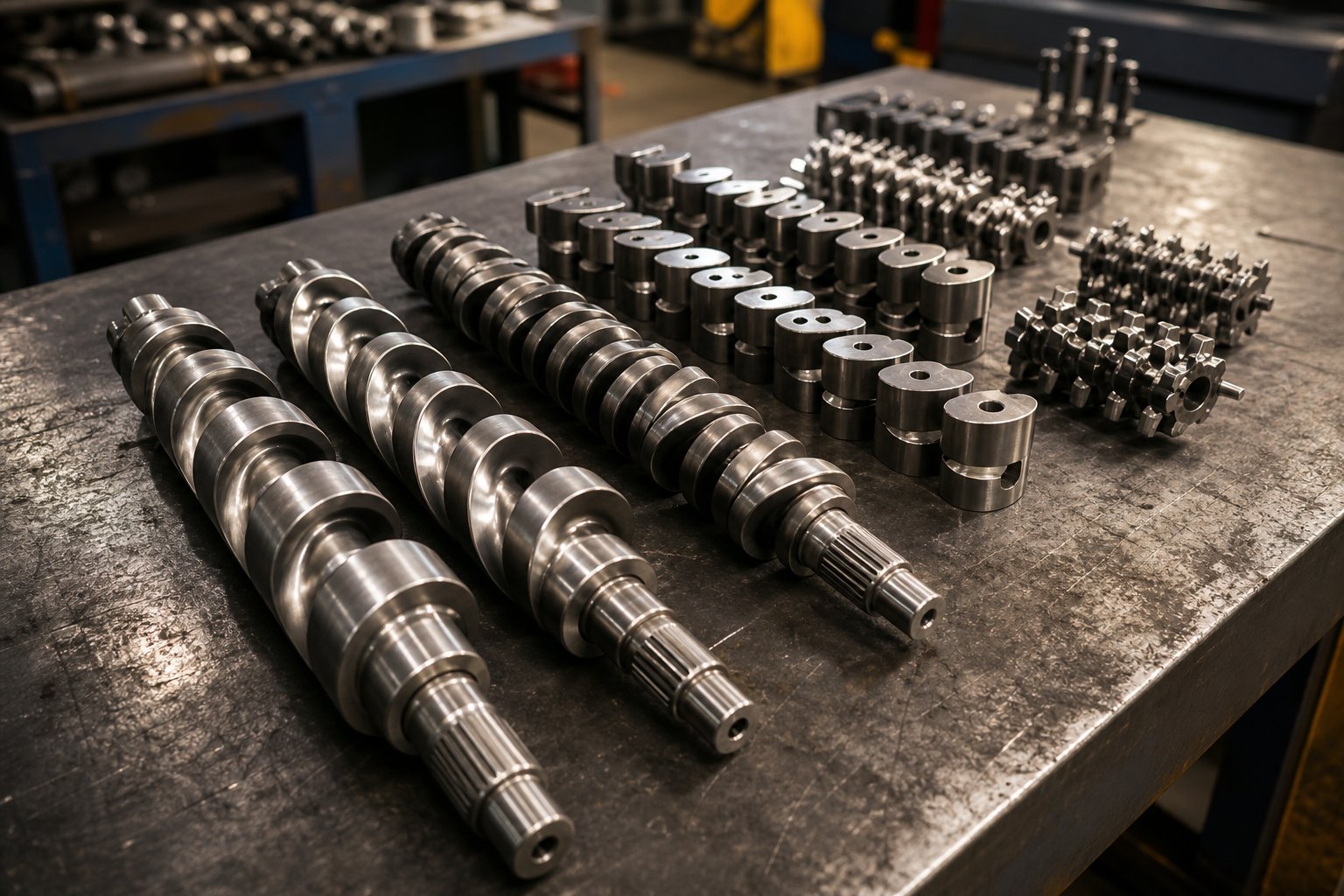
The core principle is straightforward: a co-rotating twin screw is assembled from individual elements that slide onto a splined shaft, and each element type creates a distinct flow behavior. Conveying elements transport material forward. Kneading blocks generate shear and mixing. Reverse elements push material backward to build pressure seals. Distributive mixing elements redistribute particles without crushing them. The art — and it genuinely is an art backed by engineering — lies in sequencing these elements so the material undergoes exactly the right transformations at exactly the right points along the barrel.
Here's how that sequence maps out for filler masterbatch compounding, zone by zone:
| Screw Zone | Recommended Element Types | Function in Filler Masterbatch Processing |
|---|---|---|
| Feed Zone | Large-pitch conveying elements (1.5D–2D pitch) | Rapidly pull resin pellets and pre-mixed powder into the barrel. High free volume prevents bridging and allows air to escape backward through the hopper. Starve-fed operation keeps fill level partial, avoiding torque spikes. |
| Melting Zone | Progressively tighter-pitch conveying elements transitioning to forward kneading blocks (45° stagger, wide discs) | Gradually compress material against the barrel wall for heat transfer. Wide-disc, low-stagger kneading blocks initiate melting through moderate shear without generating excessive melt temperature. The goal is a fully molten carrier before filler introduction at the side feeder. |
| Primary Mixing Zone | Kneading blocks (60°–90° stagger, narrow to medium discs) followed by distributive mixing elements (ZME, TME, or SME) | High-stagger kneading blocks deliver the dispersive shear needed to fracture filler agglomerates. Narrower discs intensify local pressure fluctuations, improving deagglomeration. Distributive mixing elements (toothed, screw, or turbine types) then redistribute those freed particles evenly throughout the melt without adding excessive energy. |
| Venting Zone | Reverse kneading block (or short reverse conveying element) upstream of vent port, followed by large-pitch conveying elements under the vent opening | The reverse element creates a melt seal — a fully filled, pressurized plug — that prevents melt from escaping through the vent port. Downstream, large-pitch elements reduce fill level and pressure, exposing maximum melt surface area for moisture and volatile release. |
| Discharge Zone | Tight-pitch conveying elements (0.5D–1D pitch) | Build stable, consistent die pressure for uniform strand extrusion. Tight pitch compresses the melt and meters it smoothly into the die plate, reducing pressure pulsation that would cause uneven strand diameters. |
That table gives you the structural skeleton. The real performance tuning happens inside the mixing zone — specifically in how you arrange kneading blocks and select distributive mixing elements.
Kneading Block Arrangement and Mixing Element Selection
Imagine a stack of oval-shaped discs threaded onto a shaft, each one rotated slightly relative to its neighbor. That's a kneading block. Three variables control its behavior: disc width, the number of discs in the stack, and the stagger angle — the angular offset between adjacent discs.
Here's where it gets interesting for filler masterbatch. Each variable does something different to the material:
- Narrow discs (shorter axial length per disc) create more frequent flow disruptions along the screw axis. Each disc-to-disc transition forces the melt to accelerate, decelerate, and change direction, generating intense local pressure fluctuations. Research using 3D CFD flow simulations with particle tracking confirmed that narrow-disc kneading blocks produce higher shear stresses on individual particles compared to wider discs — exactly what you need to crack apart stubborn filler agglomerates.
- Wide discs create smoother flow paths with gentler shear. They're better suited for distributive mixing — spreading particles around without pulverizing them. If you're compounding talc and need to preserve platelet aspect ratio, wider discs in the mixing zone are your friend.
- Low stagger angles (30°–45°) maintain significant forward conveying action alongside the mixing. Material moves through the kneading block relatively quickly, experiencing moderate shear for a shorter time. These favor distributive mixing and are ideal for heat-sensitive carrier resins.
- High stagger angles (60°–90°) drastically reduce net forward conveying. Material dwells longer in the block, getting worked harder with higher shear stresses. A 90° (neutral) kneading block has essentially zero pumping action — material oscillates back and forth, maximizing back-mixing and dispersive intensity. The same particle tracking study found that kneading blocks with 90° stagger achieved better distributive mixing quality (lower MQ index values) than those at 45°, validating what experienced compounders observe on the production floor.
So why does stagger angle affect CaCO3 and BaSO4 differently? Consider the physics. CaCO3 agglomerates at a Mohs hardness of 3 are held together by relatively moderate interparticle forces — van der Waals attraction and mechanical interlocking. These clusters break apart under modest dispersive stress. A medium-stagger kneading block (60°) with wide-to-medium discs typically provides enough deagglomeration without overheating the melt or over-wearing the barrel.
BaSO4, on the other hand, is denser and harder (Mohs 3–3.5), with particles that pack tightly and resist separation. Breaking those agglomerates demands higher peak shear stresses — which means narrower discs and steeper stagger angles (75°–90°). But here's the trade-off that catches people off guard: aggressive kneading blocks on BaSO4 also accelerate barrel wear because the harder particles are being forced through tighter clearances at higher pressures. You're essentially grinding abrasive mineral against your barrel bore under maximum stress. The screw profile must balance dispersion effectiveness against wear economics — a calculation that changes with every batch of filler you buy.
Beyond kneading blocks, distributive mixing elements fill a critical gap. Toothed mixing elements (ZME) use interlocking tooth profiles to repeatedly split, fold, and recombine the melt stream. The CFD simulation data from Paderborn University's research showed ZME elements achieving the best distributive mixing quality among all tested element types — outperforming even 90° kneading blocks — while simultaneously generating the highest maximum shear stresses for dispersive mixing. That dual capability makes ZMEs particularly valuable in a filling masterbatch machine extruder for modification, where you need thorough deagglomeration and uniform distribution in a compact screw length. Screw mixing elements (SME) and turbine mixing elements (TME) achieve similar goals through different geometries — slotted flights and multi-lobed profiles respectively — each offering slightly different balances of distributive and dispersive action.
Adapting Screw Profiles for Different Filler Loadings
A screw profile optimized for 60% CaCO3 in LDPE will not work at 80% loading. This isn't a minor adjustment — it's a fundamental redesign, and failing to make that redesign is one of the most common reasons producers struggle when they try to push loading higher on an existing filling masterbatch machine/extruder for modification.
At 60% filler loading, the carrier resin still represents 40% of the compound by weight — enough to form a continuous melt phase that fully wets every particle and transmits shear forces effectively. The screw profile can afford aggressive mixing: tight-stagger kneading blocks, multiple mixing zones, and moderate conveying pitches. There's sufficient resin to absorb the mechanical energy without overheating, and the compound remains fluid enough to build stable die pressure.
At 80% loading, the picture changes dramatically:
- Less resin means less lubrication. With only 20% carrier by weight, the thin resin film coating each particle is stretched to its limit. Aggressive kneading blocks that worked at 60% now generate excessive friction, torque spikes, and localized overheating because there isn't enough polymer melt to cushion the particle-to-particle and particle-to-metal contacts.
- More open conveying volume is mandatory. The sheer bulk of mineral powder at 80% loading requires larger-pitch conveying elements — particularly in the feed and side-feeder intake zones — to physically accommodate the volume of incoming material. A screw profile that was partially filled at 60% loading becomes fully packed and choked at 80%, causing pressure surges and inconsistent output.
- Gentler mixing replaces aggressive dispersion. Counterintuitively, ultra-high-loading formulations benefit from shorter kneading block sections with lower stagger angles and wider discs. The strategy shifts from "apply maximum shear to break agglomerates" toward "apply just enough shear to wet and distribute, then let the compound move forward." Distributive mixing elements like ZMEs become even more important because they rearrange the melt without the intense pressure buildup of tight kneading blocks.
- Multiple side-feed points replace single filler introduction. Rather than dumping all the filler at one downstream port, splitting the mineral feed across two side feeders — introducing 40% at the first port and the remaining 40% further downstream — gives the resin more time and more barrel length to absorb each increment of filler. This split-feeding approach keeps local fill levels manageable and prevents the torque overloads that plague single-point high-loading configurations.
- Venting becomes more critical. More filler means more surface moisture and more trapped air entering the barrel per kilogram of output. The venting zone may need to be extended — or a second vent port added — to handle the increased volatile load. The reverse element creating the melt seal before the vent must be carefully sized: too aggressive and it creates a pressure spike that the torque-limited compound can't tolerate; too mild and the seal leaks, allowing melt to escape through the vent port.
The bottom line? Screw profile design is never static. Every significant change in filler loading, filler type, or carrier resin demands a corresponding profile adjustment. This is precisely the modularity advantage that makes twin screw technology dominant in filler masterbatch production — but only if you actually use that modularity rather than running the same generic screw configuration for every formulation. Getting the screw profile right sets the stage for the next challenge: understanding the specific technical barriers that emerge at each filler loading threshold, and the feeding, temperature, and speed strategies needed to push past them.
Pushing Filler Loading Higher Without Sacrificing Output Quality
Screw profiles define what's physically possible inside the barrel. But the real question every production manager eventually asks is simpler and more urgent: how high can we actually push filler loading — and what breaks when we go too far? The answer isn't a single number. It's a series of escalating technical barriers, each demanding a different equipment and process strategy. Suppliers rarely walk you through these thresholds honestly because doing so reveals just how much the demands on your CaCO3 filler masterbatch extruder machine change as loading climbs from a comfortable 55% to an ambitious 82%.
Technical Challenges at 50% Through 85% Filler Loading
Think of filler loading as a staircase with three distinct landings. At each landing, the physics inside the barrel shift — sometimes subtly, sometimes dramatically — and the extruder, feed system, and downstream equipment must adapt accordingly.
Standard loading (50–65%) is the comfort zone for most filler masterbatch plastic extruder setups. The carrier resin still makes up 35–50% of the compound by weight, which means there's plenty of molten polymer to wet particle surfaces, transmit shear forces, and maintain a cohesive melt stream through the die. Torque requirements stay well within the capacity of standard gearboxes (specific torque of 6–8 Nm/cm³ is usually sufficient). Dispersion is achievable with moderate kneading block configurations because enough resin exists to penetrate and break apart agglomerates. Die pressure remains stable, strands hold together during cooling, and pellet quality is consistent. The main challenges at this tier are routine — maintaining feed accuracy, controlling moisture, and managing gradual barrel wear. For operations just entering filler masterbatch production, this is the range to master first.
High loading (65–75%) is where things get interesting — and where inexperienced operators start running into problems they didn't expect. The resin fraction drops to 25–35%, which crosses a critical threshold: filler particles begin competing for the limited polymer available to coat them. Dispersion difficulty rises sharply because the thin resin film on each particle struggles to fully wet every surface, leaving dry agglomerates that show up as specks in films and weak spots in molded parts. Torque climbs steeply as melt viscosity increases — specific torque demands often reach 9–11 Nm/cm³, and operators who aren't monitoring motor load closely will experience unexpected trips. Feed system accuracy becomes critical: at 70% loading, a 2% feeding error translates into a significant composition shift that the end user will notice. This is also the loading range where side feeding becomes practically mandatory rather than optional. Attempting to introduce all the filler through the main hopper overwhelms the feed zone before the resin melts, creating plugging, torque spikes, and inconsistent output.
Ultra-high loading (75–85%+) pushes the filling masterbatch extruder to its engineering limits. With only 15–25% carrier resin by weight, the compound behaves less like a polymer melt and more like wet sand being forced through a tube. Torque demand is extreme — specific torque ratings of 11–13 Nm/cm³ or higher are typical, and even high-torque-density gearboxes can reach their ceiling. Dispersion becomes the defining challenge: there simply isn't enough resin to fully wet every particle, and aggressive mixing generates dangerous heat buildup without the thermal buffer that a resin-rich melt provides. Die pressure instability worsens because the low-melt-strength compound can't maintain consistent flow through all die holes simultaneously, causing individual strands to pulse, thin out, and break during pelletizing. Strand breakage rates climb from occasional to persistent, and switching from strand cutting to underwater or water-ring pelletizing sometimes becomes the only viable option. Every percentage point above 80% compounds these challenges exponentially.
| Dimension | Standard Loading (50–65%) | High Loading (65–75%) | Ultra-High Loading (75–85%+) |
|---|---|---|---|
| Primary Technical Challenges | Feed accuracy, moisture control, gradual barrel wear | Incomplete filler wetting, torque spikes, feed zone plugging, early dispersion defects | Extreme torque demand, severe dispersion difficulty, die pressure instability, frequent strand breakage |
| Feed Strategy | Main hopper (resin + filler pre-mix) or single side feeder; volumetric feeders acceptable | Resin via main hopper, filler via downstream side feeder; gravimetric feeders strongly recommended | Resin via main hopper, filler split across two side feeders; gravimetric loss-in-weight feeders mandatory |
| Screw Speed Tendency | Moderate to high (300–600 RPM) for good dispersion with acceptable wear | Moderate (250–500 RPM); balance between dispersion quality and heat generation | Lower range preferred (200–400 RPM) to limit shear heating, torque overload, and accelerated wear |
| Barrel Wear Rate | Baseline — predictable replacement cycles (e.g., 8,000–12,000 hours for CaCO3) | 1.5–3x baseline; accelerated by higher filler volume fraction and increased contact pressure | 3–5x baseline or higher; bimetallic or tungsten carbide barrel liners often essential |
Feed System Strategy and Temperature Profile Guidance
The table above hints at a pattern: as loading increases, the feed system transitions from a supporting role to the single most critical variable determining success or failure. Here's why that transition matters so much in practice.
Volumetric feeders — simple screw or vibratory devices that deliver material at a set volume per revolution — work adequately at standard loadings where a pre-mixed blend of resin and filler enters the main hopper. The composition is relatively forgiving of minor feed fluctuations. Above 65% loading, that forgiveness disappears. A volumetric feeder can't account for changes in powder bulk density caused by humidity, compaction, or lot-to-lot variation. When your formulation is 70% CaCO3 and the feeder delivers 73% for twenty minutes because the powder packed slightly denser in the hopper, the resulting pellets are off-spec — and you won't know until a downstream QC test catches it.
Gravimetric loss-in-weight feeders solve this by continuously weighing the hopper and adjusting feed rate in real time to maintain a target mass flow. They're more expensive, but at high and ultra-high loadings, they're not optional — they're the difference between consistent product and scrap. Every filling masterbatch extruder line targeting above 65% loading should budget for gravimetric metering on both the resin and filler streams.
Feed sequence deserves equal attention. The most reliable approach for high-loading formulations follows a clear logic: introduce carrier resin through the main hopper so it melts completely in the first third of the barrel, then add filler downstream through a side feeder into the already-molten resin. This "melt first, fill second" strategy maximizes the resin's ability to wet incoming particles and avoids the torque chaos that results from trying to melt resin and incorporate massive volumes of powder simultaneously. For ultra-high loadings above 75%, splitting the filler feed across two side feeder ports — typically positioned at roughly the 40% and 60% barrel length marks — distributes the volumetric burden and gives each increment of filler adequate mixing length before the next wave arrives.
Temperature profiles shift in lockstep with loading levels. At standard loading, a gradually ascending profile — starting around 140–150°C at the feed throat and rising to 180–200°C through the mixing zones (for PE carriers) — works well. The ample resin absorbs frictional heat without overheating. At ultra-high loading, that same ascending profile can cause problems because the reduced resin fraction means less thermal mass to absorb shear-generated heat. Experienced operators often flatten or even invert the temperature profile in the mixing zones — setting barrel heaters to 160–170°C while the filler's friction generates the remaining energy needed. The goal is preventing the melt from thinning out excessively: if barrel temperatures push melt viscosity too low, the carrier loses its ability to transmit shear forces to filler agglomerates, and dispersion quality collapses despite the screws turning at full speed. For PP carriers, barrel temperatures naturally run 20–30°C higher across all zones, but the same flattening principle applies at elevated loadings.
Screw speed strategy follows a similar loading-dependent logic. Higher RPM generates more shear — beneficial for dispersion — but also more frictional heat, higher torque demand, and faster barrel wear. At standard loadings, you can afford to run 400–600 RPM on a typical 65mm machine because the resin-rich melt absorbs energy well and wear is moderate. At ultra-high loadings, dropping to 200–350 RPM reduces all three penalties simultaneously, though it sacrifices some throughput. The trade-off isn't just mechanical — it's economic. Running a filler masterbatch plastic extruder at 500 RPM with 80% CaCO3 might deliver 15% more throughput than 300 RPM, but barrel and screw replacement costs can double, and motor energy consumption rises disproportionately. The smart play is finding the lowest RPM that still achieves acceptable dispersion quality, then making up throughput with larger machine diameters rather than higher speed.
Pushing filler loading higher is always a balancing act — torque against dispersion, speed against wear, throughput against quality. But even when all these variables are dialed in correctly, a different category of problems can undermine your entire operation: the subtle setup mistakes and overlooked cost factors that silently erode output quality and profitability over time.
Common Pitfalls in Filler Masterbatch Extrusion and How to Avoid Them
You've selected the right filler, matched the carrier resin, configured a sensible screw profile, and dialed in a loading target that your gearbox can handle. Everything should work. And yet — production stumbles. Strands snap at the water bath. Pellets come out porous. The motor trips every forty minutes. What went wrong?
More often than not, the root cause isn't a fundamental design flaw. It's a setup mistake — something subtle enough to slip past a commissioning checklist but damaging enough to tank output quality and throughput for weeks. These are the problems that no CaCO3 filling masterbatch plastic extruder machine brochure warns you about, because they only surface once you're running real formulations at production speed.
Setup Mistakes That Kill Output Quality and Throughput
Here's a practical checklist of the most common pitfalls, each paired with the engineering reason it matters and the prevention strategy that actually works:
- Insufficient filler drying. CaCO3 powder stored in a humid warehouse can carry 0.3–0.5% moisture — far above the 0.1% threshold for clean extrusion. That moisture flashes into steam inside the barrel, creating internal voids and surface porosity in the strands. Porous strands break during pelletizing, producing fines and misshapen granules. The fix? Dry filler to below 0.1% moisture content before processing, and store it in a controlled environment where humidity stays at or below 50%. Sealed containers and desiccant-equipped hoppers are cheap insurance against this problem.
- Incorrect kneading block placement. Positioning aggressive high-stagger kneading blocks too early in the barrel — before the carrier resin has fully melted — forces solid resin pellets and dry powder through intense shear zones. The result is localized overheating, premature thermal degradation of the carrier (especially PP), and paradoxically worse dispersion because the partially melted resin can't wet filler surfaces effectively. Prevention is straightforward: ensure the melting zone uses gradual compression and moderate kneading to achieve a complete melt before the material reaches the primary dispersive mixing section.
- Filler moisture and vent port plugging. This one catches people off guard. Moisture-laden filler generates steam that travels to the vent port, but if the melt seal upstream of the vent is too weak — or if partially wetted filler particles get carried upward by escaping gas — the vent opening clogs with a paste of damp powder. Once plugged, the vent can no longer remove volatiles, and internal pressure builds until the melt foams or surges. Prevention requires two actions: dry the filler properly (eliminating the root cause) and verify that the reverse element forming the melt seal before each vent port is appropriately sized to block melt migration without creating excessive pressure.
- Overfeeding filler relative to resin. When the side feeder delivers mineral powder faster than the molten resin stream can absorb it, the local filler concentration spikes above the formulation target. The melt viscosity surges, torque jumps, and the motor protection relay trips — shutting down the entire line. Restarting after a torque trip wastes 15–30 minutes and often requires purging degraded material from the barrel. Use gravimetric loss-in-weight feeders on both resin and filler streams, and set up a feed-rate interlock so the filler feeder automatically reduces output if the resin feed rate drops below its setpoint.
- Barrel temperatures set too high. This is counterintuitive — shouldn't more heat help melt and mix everything? Not necessarily. If barrel heaters push the carrier resin's melt viscosity too low, the thin, watery melt can no longer transmit enough shear stress to break apart filler agglomerates. The screws spin, the material flows, but dispersion quality collapses. You'll see undispersed specks in film test samples and elevated filter pressure values despite the strands looking visually acceptable. The barrel temperature for PE carriers should stay in the 150–180 degree Celsius range through the mixing zones. Going 10–15 degrees above that sweet spot can be enough to drop dispersion quality below spec.
- Neglecting die plate hole sizing. The die is the last component in the flow path, and it governs back pressure for the entire barrel. Too few holes — or holes that are too small in diameter — create excessive restriction that overloads the gearbox, increases melt temperature through viscous dissipation, and forces the compound through narrow openings where high-filler melts are prone to fracture. Too many holes or oversized diameters reduce back pressure below the level needed for uniform flow distribution, causing some strands to run fast and others to starve. For compounds above 70% mineral loading, die holes of 3–4 mm diameter with a land length (hole depth) of 8–12 mm typically provide the right balance. Recalculate every time you change formulation or throughput rate.
Energy, Wear Costs, and ROI Considerations
Setup mistakes cost you in scrap and downtime. But even a perfectly running filling masterbatch granule extruder line accumulates costs that many producers underestimate — costs that compound over months and ultimately determine whether your operation is genuinely profitable or just busy.
Energy consumption is the silent heavyweight. Twin screw compounding typically consumes 0.15–0.35 kWh per kilogram of output, depending on filler loading, screw speed, and extruder efficiency. That range looks narrow until you multiply it by a 500 kg/h line running two shifts daily, 300 days a year — where the difference between 0.20 and 0.30 kWh/kg translates into tens of thousands of dollars annually. Machine selection matters here: extruders with high-torque-density gearboxes deliver more work per RPM, allowing lower screw speeds for equivalent dispersion — which directly reduces specific energy consumption. Older machines or undersized drives force higher RPM to compensate for lower torque, burning more electricity and generating more wear for the same output.
Barrel and screw wear is the cost most directly tied to filler type and loading. A filling masterbatch pelletizer extruder processing 60% GCC CaCO3 through nitrided barrels might achieve 8,000–12,000 operating hours before bore tolerances exceed acceptable limits. Push that loading to 80%, and the same barrel may last only 3,000–5,000 hours. Replacement screw elements follow a similar curve. The financial impact isn't just the cost of replacement parts — it's the 1–3 days of production lost during changeout, the risk of quality drift as wear progresses between replacements, and the maintenance labor to perform the swap.
These factors interact in ways that change the ROI equation for extruder selection. A lower-priced machine with standard nitrided barrels looks attractive on the purchase order, but if its barrel life at your target loading is half that of a machine equipped with bimetallic or carbide-lined barrels, the total cost of ownership over five years can be significantly higher. Specific energy consumption follows a similar pattern — a machine that costs 15% more upfront but delivers 20% lower energy consumption per kilogram pays for the difference within 18–24 months at typical production volumes.
The smartest way to evaluate any filler masterbatch extruder investment is to calculate cost per kilogram of saleable output — factoring in energy, wear parts, labor, downtime, and scrap rate — rather than comparing purchase prices alone. That calculation inevitably leads to the same conclusion: the barrel is the wear-critical component that drives the largest share of ongoing operational cost, and choosing the right barrel metallurgy for your specific filler and loading level is one of the highest-leverage decisions you'll make.
Twin Screw Barrel Selection and Wear Management Strategies
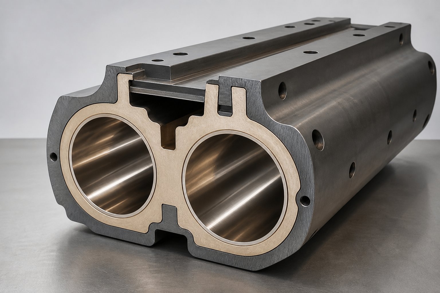
The previous section landed on a conclusion worth repeating: the barrel is the single component most responsible for ongoing operational cost in filler masterbatch production. Screws wear too, of course, but barrels are larger, more expensive to replace, and — critically — their bore geometry directly governs dispersion consistency, pressure stability, and melt temperature uniformity. When bore wear opens the screw-to-barrel clearance beyond roughly 0.3 mm, output quality deteriorates in ways that no amount of process parameter tuning can compensate for. Melt leaks backward past the kneading blocks, reducing effective shear on filler agglomerates. Pressure pulsation increases at the die. Temperature uniformity suffers as material circulates through widened gaps instead of moving forward.
That's why understanding barrel metallurgy isn't optional — it's the difference between a filler masterbatch extruder factory running predictable maintenance cycles and one firefighting unplanned shutdowns every quarter.
Barrel Metallurgy and Wear Protection for Abrasive Fillers
Three barrel construction strategies exist, each offering a distinct level of wear protection at a different price point. Matching the right option to your filler type and loading level prevents both over-spending and under-protecting.
Nitrided steel barrels represent the baseline. The bore surface of a nitriding-grade alloy steel — typically 38CrMoAlA or equivalent — is hardened by diffusing nitrogen at 500-550 degrees Celsius, producing a case depth of roughly 0.4-0.6 mm with surface hardness of 950-1100 HV (approximately 65-70 HRC). That thin hard layer performs well against adhesive wear from clean polyolefins, but it has a fundamental limitation for filler masterbatch applications: once abrasive mineral particles grind through that 0.5 mm case, the soft steel core (280-320 HB) beneath is exposed and wear accelerates dramatically. For a filler masterbatch extruder running 60%+ CaCO3, nitrided barrels may last only 12-18 months before bore tolerances become unacceptable — compared to 3-5 years for the same barrel processing unfilled PE.
Bimetallic barrels solve this through a fundamentally different architecture. Instead of hardening the surface of a single steel, a wear-resistant alloy liner is centrifugally cast inside the barrel shell, creating a metallurgically bonded layer 1.5-3.0 mm thick — roughly 3-6 times the effective wear reserve of a nitrided barrel. Two main liner families serve filler masterbatch applications:
- Iron-based alloys (Fe-Cr-B): Chromium and boron carbides dispersed in an iron matrix deliver 58-62 HRC hardness. This is the workhorse choice for CaCO3 and talc filler masterbatch compounding — providing 2-3 times longer service life than nitrided barrels in moderate-wear applications at roughly 1.8-2.5 times the initial cost.
- Nickel-based alloys (Ni-Cr-B-W): These add corrosion resistance on top of abrasion protection, reaching 60-65 HRC. They're the right choice when your formulation includes flame retardants, PVC-based carriers, or other chemically aggressive additives alongside mineral fillers.
Tungsten carbide protection — either as WC-rich particles in a centrifugally cast liner or as HVOF-sprayed coatings — represents the highest tier. Surface hardness reaches 65-75 HRC, and service life in severely abrasive applications can extend 3-7 times beyond standard nitrided barrels. This level of protection is typically reserved for BaSO4 at high loadings, glass fiber compounding, or any filler masterbatch extruder manufacturer's line processing ultra-high mineral content (80%+) where the sheer volume of abrasive material passing through the bore makes anything less a false economy.
The initial cost premium for bimetallic barrels — typically 1.8-3.0 times a nitrided equivalent — discourages some buyers. But the total cost picture tells a different story. A practical example from a PVC cable compound line processing 30% CaCO3 through a 65mm twin screw extruder illustrates the math clearly: the nitrided barrel required three replacements over five years (total barrel hardware cost: $36,000 plus $24,300 in downtime), while a single bimetallic barrel lasted the entire period at $28,000 — cutting barrel-related costs by more than 60%.
When barrel wear does reach its limit and replacement is needed, sourcing precision-manufactured barrels that maintain tight bore tolerances becomes critical. Even small deviations in center distance or bore geometry can cause abnormal wear patterns or screw seizure. Suppliers like NANHAIYA, who specialize in parallel twin screw barrel manufacturing for masterbatch producers and high-wear compounding applications, serve this replacement and custom barrel market — offering barrels engineered to match specific extruder specifications and processing demands.
Matching Extruder Size Class to Your Production Scale
Bore diameter determines the fundamental throughput capacity of your machine, and choosing the wrong size class leads to either wasted capital or a bottleneck you can never screw-speed your way out of. Here's how standard size classes map to practical filler masterbatch production scales:
| Extruder Size Class (Bore Diameter) | Typical Throughput Range (Filler Masterbatch) | Motor Power Range | Recommended Production Scale |
|---|---|---|---|
| 35-40 mm | 30-80 kg/h | 15-30 kW | Lab/pilot lines, small-batch specialty masterbatch, R&D formulation development |
| 50-55 mm | 80-200 kg/h | 37-75 kW | Small-to-mid production, niche applications, low-volume custom formulations |
| 62-75 mm | 200-600 kg/h | 75-200 kW | Mid-scale commercial production — the most common size class for dedicated filler masterbatch operations |
| 80-95 mm+ | 500-2,000+ kg/h | 200-600+ kW | High-volume commodity filler masterbatch, multi-shift continuous production, large regional suppliers |
Several practical considerations influence the size decision beyond raw throughput numbers. Larger machines deliver lower specific energy consumption (kWh/kg) because motor efficiency scales favorably — but they require larger capital investment, more floor space, and higher minimum batch sizes. A 95mm extruder running at 30% capacity to fill a small order wastes energy and produces inconsistent quality because the screw channels are under-filled. Conversely, a 50mm machine running at maximum throughput to meet growing demand operates at the ragged edge of its torque and thermal limits, accelerating wear and narrowing the process window to a razor-thin margin.
When evaluating a filler masterbatch extruder for sale, match the size class to your realistic production volume — not your most optimistic projection. You'll notice that most successful filler masterbatch extruder suppliers in the 62-75mm range can accommodate the majority of mid-market operations, with the flexibility to run both standard 60% loading formulations and more demanding 75-80% products without fundamental equipment changes.
For operations sourcing replacement barrels or evaluating pe pp filler masterbatch extruder suppliers for wear components, remember that barrel metallurgy matters more than the brand name stamped on the extruder frame. A well-made bimetallic barrel from a specialist filler masterbatch extruder supplier who understands compounding tolerances will outperform a generic replacement — regardless of whether your machine was built in Germany, Japan, or China. Focus on metallurgical specifications, bore tolerance documentation, and the supplier's experience with your specific application rather than geography alone.
Barrel selection and sizing determine your cost structure for years to come. But even the best barrel can't compensate for what happens after the pellets leave the die — which is why the final piece of the puzzle involves measuring whether your output actually meets specification, and preparing for the industry shifts that will reshape filler masterbatch production in the coming years.
Quality Control Methods and Emerging Trends in Filler Masterbatch Production
A perfectly configured filler masterbatch compounding extruder, running the right screw profile and barrel metallurgy, still produces pellets that need to prove themselves. The question shifts from "can we make it?" to "does what we made actually meet spec?" Surprisingly few producers apply rigorous, systematic quality control to their filler masterbatch output — and even fewer equipment guides explain which tests matter, what they reveal, and where the acceptable boundaries lie. Meanwhile, the industry itself is evolving in ways that will reshape how every customized filler masterbatch extruder is designed and operated within the next several years.
Essential Quality Control Tests for Filler Masterbatch Pellets
Quality control for filler masterbatch isn't about running every test in a polymer lab manual. It's about selecting the handful of measurements that catch the failure modes most likely to damage downstream processing — and running them consistently enough to spot drift before it becomes a customer complaint. Here are the critical tests every operation should standardize:
- Filter pressure value (FPV) test. This is the gold standard for dispersion quality assessment. A measured quantity of masterbatch is extruded through a fine screen pack (typically 200 mesh), and the pressure buildup across that screen is recorded over time. Undispersed filler agglomerates, gels, and contaminants clog the screen and drive pressure higher. A low, stable FPV indicates clean, well-dispersed masterbatch. For film-grade CaCO3 filler masterbatch, FPV values should remain consistently low across batches — any sudden increase signals a dispersion breakdown that could cause frequent screen changes, downtime, and high wastage at the converter's plant. This single test reveals more about your filler masterbatch extruder equipment performance than any other measurement.
- Thin film visual inspection. Press or blow a thin film (25-50 micrometers) from the masterbatch let down into base resin at the intended dosing ratio. Hold it against a light box and examine for specks, agglomerates, streaks, and uneven opacity. This low-tech method catches dispersion defects that even FPV testing can miss — particularly large, soft agglomerates that deform under pressure but remain visually distinct in a stretched film. It's fast, inexpensive, and provides immediate feedback to the operator.
- Melt flow index (MFI) measurement. MFI verifies that the masterbatch's flow behavior stays within the processing window required by downstream converters. Batch-to-batch MFI consistency confirms stable filler loading, uniform carrier resin quality, and repeatable compounding conditions. When MFI drifts outside the acceptable range — typically defined as plus or minus 10-15% of the target value — it flags either a composition shift (filler over- or under-feeding) or a thermal processing issue (resin degradation raising MFI, or insufficient melt temperature lowering it). For LDPE-carrier masterbatch used in film extrusion, the compound MFI should stay compatible with the base polymer's range to avoid poor mixing, high torque, and streaking during converting.
- Ash content testing. This is how you confirm actual filler loading matches formulation targets. A sample is burned in a muffle furnace at 550-600 degrees Celsius, incinerating all organic content (carrier resin and additives) and leaving only the mineral residue behind. The remaining ash, weighed as a percentage of the original sample, directly reveals the true filler content. Acceptable batch-to-batch variation depends on the application, but most serious producers hold ash content within plus or minus 1-2% of the target loading. A reading of 72% ash content on a product specified at 75% means the feeder calibration needs attention — immediately.
- Moisture content control. Karl Fischer titration or loss-on-drying methods measure residual moisture in finished pellets. For standard polyolefin-based filler masterbatch, moisture should stay below 0.1%. Elevated moisture causes bubbles, voids, surface haze, and pinholes when the converter processes the pellets — defects that get blamed on the converter's equipment but originate from inadequate drying or packaging at the masterbatch producer's facility. Moisture-barrier packaging and controlled warehouse humidity are just as important as the number itself.
These five tests — FPV, visual film inspection, MFI, ash content, and moisture — form a minimum QC framework that catches the vast majority of quality failures before pellets ship. Consistency across batches matters more than any single absolute value. A filling masterbatch machine/extruder that produces pellets with predictable, repeatable test results run after run is delivering real value, and that repeatability traces directly back to equipment condition. Worn barrels with widened bore tolerances degrade dispersion quality gradually — often so slowly that operators don't notice until FPV results spike or a downstream customer reports film defects. Maintaining tight barrel bore geometry through timely replacements, using precision-manufactured components like NANHAIYA's parallel twin screw barrel solutions designed for high-wear compounding applications, helps sustain the consistent QC outcomes that keep customers coming back.
Emerging Trends Reshaping Filler Masterbatch Extrusion
The filler masterbatch industry isn't standing still. Several converging forces are pushing the technology into new territory — and the producers who adapt early will hold a meaningful competitive advantage.
Nano-fillers are entering commercial reality. Nano-calcium carbonate (particle sizes below 100 nanometers), nano-clay, and nano-silica offer dramatic property improvements at far lower loading levels compared to conventional micro-scale fillers. But their enormous surface area — hundreds of square meters per gram — creates dispersion challenges that push conventional filler masterbatch extruder equipment to its limits. Standard kneading block configurations struggle to break apart nano-particle agglomerates that are held together by surface forces orders of magnitude stronger than those in micro-CaCO3. Successfully compounding nano-fillers demands higher specific energy input, longer effective mixing lengths, and screw profiles specifically designed around distributive mixing elements like ZMEs. Expect this to drive demand for customized filler masterbatch extruder configurations optimized for nano-scale dispersion rather than brute-force high-loading capacity.
Bio-based carrier resins are gaining traction. As sustainability mandates tighten across packaging and consumer goods markets, bio-PE (derived from sugarcane ethanol), PLA, and PHA are emerging as potential carrier resin alternatives to fossil-based polyolefins. The processing characteristics differ significantly — PLA, for instance, is far more sensitive to thermal degradation and moisture than LDPE — which means barrel temperature profiles, screw configurations, and drying protocols all need rethinking. For filler masterbatch producers, this creates both a challenge and an opportunity: early movers who validate bio-resin carrier formulations on their existing lines position themselves for a market segment that's growing faster than commodity PE-based masterbatch.
Ultra-high loading formulations keep climbing. Cost reduction pressure from converters — particularly in price-sensitive markets like woven bags, garbage bags, and disposable packaging — continues to push filler loading targets upward. Formulations at 82-85% CaCO3 that seemed impractical five years ago are now routine at plants with properly designed twin screw lines. The enabling technologies are better surface treatments (advanced titanate and silane chemistries that allow thinner resin films to wet more particle surface), higher-torque-density gearboxes that handle the extreme viscosity at minimal resin content, and split-feeding strategies that distribute the filler intake burden across multiple barrel positions.
Energy-efficiency innovations are reshaping machine economics. Modern high-torque-density gearboxes with mechanical efficiencies exceeding 96-98% reduce wasted power in the drive train. Advanced vector-controlled variable frequency drives keep motors running at optimal torque-speed points rather than fixed setpoints, cutting specific energy consumption by 10-15% compared to older control strategies. Nano-insulation on barrel heater bands minimizes radiant heat loss to the factory environment, lowering heater duty cycles by 5-8%. Together, these innovations can reduce the energy cost per kilogram of filler masterbatch output by 20-30% compared to machines built a decade ago — a difference that compounds into substantial savings over the five-to-ten-year operational life of a typical line.
The filler masterbatch twin screw extruder has matured from a simple compounding tool into a precision system where every variable — filler mineralogy, carrier resin chemistry, screw element geometry, barrel metallurgy, feed strategy, temperature profile, and quality control protocol — interacts with every other. Understanding those interactions, rather than relying on generic supplier recommendations, is what separates producers who consistently deliver high-quality pellets at competitive cost from those who spend their days chasing problems they can't quite diagnose. The information in this guide won't replace hands-on experience, but it should give you the framework to ask sharper questions, make better-informed equipment decisions, and push your operation closer to its real potential.
Frequently Asked Questions About Filler Masterbatch Twin Screw Extruders
1. What is the maximum filler loading achievable in a twin screw extruder?
Most well-configured co-rotating twin screw extruders can achieve filler loadings of 80-85% by weight when paired with the right carrier resin, surface-treated filler, and process strategy. Reaching ultra-high loadings above 75% requires gravimetric loss-in-weight feeders, split filler feeding across two side feeder ports, lower screw speeds to manage torque, and gentler screw profiles with more open conveying volume. EVA carrier resins with MFI values of 15-30 g/10 min are often preferred for pushing past 80% because their polar vinyl acetate groups improve mineral particle wetting at minimal resin content.
2. Why are co-rotating twin screw extruders better than single screw machines for filler masterbatch?
Co-rotating twin screw extruders offer four critical advantages over single screw designs for filler compounding. Their self-wiping intermeshing screws eliminate dead zones where agglomerates can hide. Modular barrel and screw configurations allow profiles to be customized for specific filler types and loading levels. Superior dispersive and distributive mixing breaks apart agglomerates and spreads particles uniformly. Finally, the high free volume created by favorable Do/Di ratios (1.65 or higher) accommodates the large volumes of low-bulk-density mineral powder that high-loading formulations demand.
3. How do you choose the right barrel material for a filler masterbatch extruder?
Barrel material selection depends primarily on filler type, loading level, and target service life. Nitrided steel barrels suit low-wear applications or standard loadings below 60% with talc. Bimetallic barrels with iron-based alloy liners (Fe-Cr-B) provide 2-3 times longer life for CaCO3 compounding at 60-80% loading. Nickel-based bimetallic liners add corrosion resistance for chemically aggressive formulations. Tungsten carbide protection is reserved for the most demanding scenarios — BaSO4, glass fiber, or ultra-high CaCO3 loadings above 80% — where abrasive volume makes lesser protection uneconomical over the barrel's lifecycle.
4. What carrier resin works best for CaCO3 filler masterbatch production?
LDPE and LLDPE are the most widely used carriers for CaCO3 filler masterbatch. LDPE's low melt viscosity at 150-190 degrees Celsius enables easy filler wetting and accepts loadings up to 80%+. LLDPE offers higher melt viscosity under the same MFI, generating greater shear for improved dispersion and producing tougher pellets. For ultra-high loadings, EVA is preferred because its polar vinyl acetate groups create stronger interactions with surface-treated minerals. The carrier resin MFI sweet spot for most CaCO3 masterbatch falls between 7-25 g/10 min, balancing filler wetting capability against pellet strength and downstream compatibility.
5. What quality control tests should be performed on filler masterbatch pellets?
Five essential QC tests form a reliable framework for filler masterbatch quality assurance. Filter pressure value (FPV) testing evaluates dispersion quality by extruding masterbatch through a fine screen and measuring pressure buildup from undispersed agglomerates. Thin film visual inspection under a light box catches specks and streaks that FPV may miss. MFI measurement confirms batch-to-batch flow consistency within a plus or minus 10-15% tolerance. Ash content testing via muffle furnace at 550-600 degrees Celsius verifies actual filler loading against targets. Moisture content testing ensures pellets remain below 0.1% to prevent downstream processing defects like bubbles and pinholes.
Written by
Nanhaiya Technical Team
Zhoushan Nanhaiya Plastic Machinery Co., Ltd.
The Nanhaiya technical team supports screw and barrel manufacturing projects through application review, technical communication, custom manufacturing coordination, and production and quality control.
Discuss Your Application
Related Articles
More insights on screw barrel technology and plastics processing.

What Nobody Tells You About Screw Barrel For Plastic Machine Design
Oct 10, 2026
Learn how screw barrel for plastic machine design affects melt quality, throughput, and wear life. Covers geometry, resin matching, troubleshooting, and sourcing.
Read Article
Single Screw Extruder for Sheet: Stop Guessing, Start Specifying
Oct 9, 2026
Learn how to specify a single screw extruder for sheet production. Covers screw geometry, resin-specific processing, troubleshooting, and maintenance best practices.
Read Article
PE Pipe Extruder Machine: What Datasheets Won't Tell You
Oct 9, 2026
Learn how a PE pipe extruder machine works, key specs explained, material grade selection, maintenance tips, and buyer guidance beyond the datasheet.
Read ArticleLooking for something else?
Search by material, symptom or product and jump straight to the relevant page.
These are navigation suggestions based on keyword matching — not a quotation, not a delivery commitment, and not a substitute for engineering review. Final specification is confirmed by our engineers against your drawings and processed material.
Need help with screw barrel selection?
Share your machine model, processed material and application. Our team can help with pricing and technical support.