


Why Structured Extrusion Troubleshooting Saves Your Production Line
Extrusion troubleshooting is the systematic process of identifying symptoms, isolating root causes, and applying corrective actions across an entire extrusion line — from the feed throat through the screw and die to downstream cooling, sizing, and haul-off equipment. It applies to every extrusion format: pipe, profile, film, sheet, and granulation.
Imagine this: you're two hours into a steady production run when the operator notices the surface finish changing. Wall thickness starts drifting. Within minutes, scrap bins are filling up. The question isn't whether something went wrong — it's what to check first. And that decision, made under pressure on the production floor, is where most operations lose time, material, and money.
The core problem isn't that operators lack skill. It's that most facilities have no repeatable diagnostic method. When quality drops, the typical response is reactive — someone tweaks a temperature zone, bumps the screw speed, adjusts haul-off tension, maybe all at once. If the defect disappears, nobody knows which change actually fixed it. If it doesn't, they've now introduced new variables on top of the original problem. Most extrusion defects trace back to interactions between material properties, equipment setup, and process conditions, so scattershot adjustments rarely land on the true root cause.
What Extrusion Troubleshooting Actually Means
A structured approach to extrusion defect diagnosis goes far beyond fixing surface blemishes. It covers the full spectrum of problems operators encounter — melt fracture, surging, voids, warpage, die lines, degradation, dimensional drift, and contamination. It also spans the entire line. A warped profile might look like a die problem, but the root cause could be asymmetric cooling twenty feet downstream. Gauge variation in blown film might point to air ring adjustment, but it could originate from inconsistent screw output. Effective diagnosis means tracing each symptom back through the full process chain rather than stopping at the most obvious suspect.
This discipline matters because extrusion defects cascade. A slightly elevated melt temperature causes subtle degradation. That degradation changes viscosity. Changed viscosity alters flow distribution across the die. Altered flow creates dimensional variation. By the time an operator spots the dimensional problem, the original cause — a failing heater band or a shift in resin lot properties — is buried under layers of secondary effects. A systematic method helps you reduce scrap and downtime in extrusion by cutting through those layers instead of chasing symptoms.
Why Most Troubleshooting Fails Before It Starts
The single most common mistake is changing multiple variables at once. An operator drops barrel zone three by ten degrees, slows the screw by five RPM, and increases cooling water flow — all in the same adjustment. Even if the product improves, there's no way to know which change mattered. Worse, one of those changes may have introduced a new instability that won't surface until the next shift. The principle of checking variables in a deliberate order — so that earlier parts of the process aren't unintentionally affected by later adjustments — is foundational to any reliable diagnostic method.
The second failure point is undocumented baselines. If you don't know what melt temperature, head pressure, screw RPM, and motor amps looked like during good production, you have no reference point when things go wrong. You're guessing at "normal" instead of comparing against a recorded standard.
Change one variable at a time and measure the result before moving to the next.
That single rule, applied consistently, transforms troubleshooting from a frustrating guessing game into a structured, repeatable process. It doesn't guarantee a fast answer every time, but it guarantees that every answer you do find is real — and that the fix will hold. The challenge, of course, is knowing exactly which variable to change first, and that requires a clear diagnostic framework.
A Five-Step Diagnostic Framework for Any Extrusion Problem
A reliable extrusion diagnostic framework for operators doesn't need to be complicated — it needs to be consistent. Whether you're running pipe, blown film, profiles, or sheet, the same five-step method applies. The key is discipline: follow the sequence every time, resist the urge to skip ahead, and let each step inform the next.
- Observe the symptom from the operator's entry point — what you see, hear, feel, or measure at the product.
- Record the current baseline conditions across the entire line.
- Isolate the variable domain where the problem most likely originates.
- Test by changing one variable at a time while monitoring the result.
- Verify the fix holds across a sustained production window.
This step by step extrusion troubleshooting method works because it mirrors how root cause analysis functions in broader manufacturing. The goal, as quality professionals emphasize, is to trace a problem to its origin — whether that origin is equipment, materials, process settings, or tooling — through a deliberate, data-collecting exercise rather than intuition alone.
Steps One Through Three — Observe, Record, Isolate
Observation starts at the product. Is the surface rough, discolored, or wavy? Are dimensions drifting in one direction or fluctuating? Is there an unusual sound from the drive or gearbox — a whine, a knock, a rhythm change? These sensory cues are your first diagnostic data. Write them down with a timestamp, not just a mental note.
Recording baseline conditions means capturing the numbers that define your current process state: melt temperature at the die, barrel zone set points, screw RPM, head pressure, motor amperage, material lot number, and even ambient temperature and humidity. If you're unsure what "normal" looks like, this is the moment you discover the gap — and the reason documenting good runs matters just as much as documenting bad ones.
Isolation is where you narrow the search. Ask yourself: did anything change right before the defect appeared? A new material lot, a shift change, an ambient temperature swing, a screen pack that's overdue? Sort the possibilities into four domains — material, machine, process settings, or tooling. This keeps you from chasing symptoms across unrelated systems. If the material lot changed an hour ago and you're now seeing gels, start there. If nothing changed but quality degraded gradually, suspect wear or buildup — a machine or tooling issue.
Steps Four and Five — Test and Verify
Testing means applying the one variable at a time extrusion troubleshooting principle in practice. You've isolated a likely domain — say, melt temperature seems too high. Don't simultaneously lower the temperature and reduce screw speed. Drop the temperature in one zone by a controlled increment, hold everything else constant, and watch the result for enough product length to see a real change. If the defect improves, you've confirmed the direction. If it doesn't, return to the previous setting before trying the next hypothesis.
This discipline matters especially because extrusion defects are interconnected. Lowering barrel temperature to reduce thermal degradation might push you below the threshold for proper melt homogeneity, introducing melt fracture or rough surface texture. Increasing screw speed to raise output can elevate shear heating, offsetting any temperature reduction you just made. Each corrective action carries a potential tradeoff, and the only way to navigate those tradeoffs safely is to isolate each change and measure its individual effect.
Every corrective action is a hypothesis — treat it as an experiment, not a permanent fix, until verified.
Verification is the step most operators skip — and it's the reason "fixed" problems reappear the next day. A defect that disappears for two minutes after an adjustment hasn't been solved. You need to confirm the correction holds across a sustained production window: enough meters of product, enough time on the clock, and ideally across a shift change or a material hopper refill. Verification also means documenting exactly what you changed and what the result was, so the next operator or the engineering team has a clear record to build on.
This framework won't tell you which variable is the culprit — that requires understanding what your instruments are actually saying. Melt temperature, head pressure, and motor amperage each carry distinct diagnostic signals, and learning to read those signals is what separates a quick diagnosis from a long shift of guesswork.
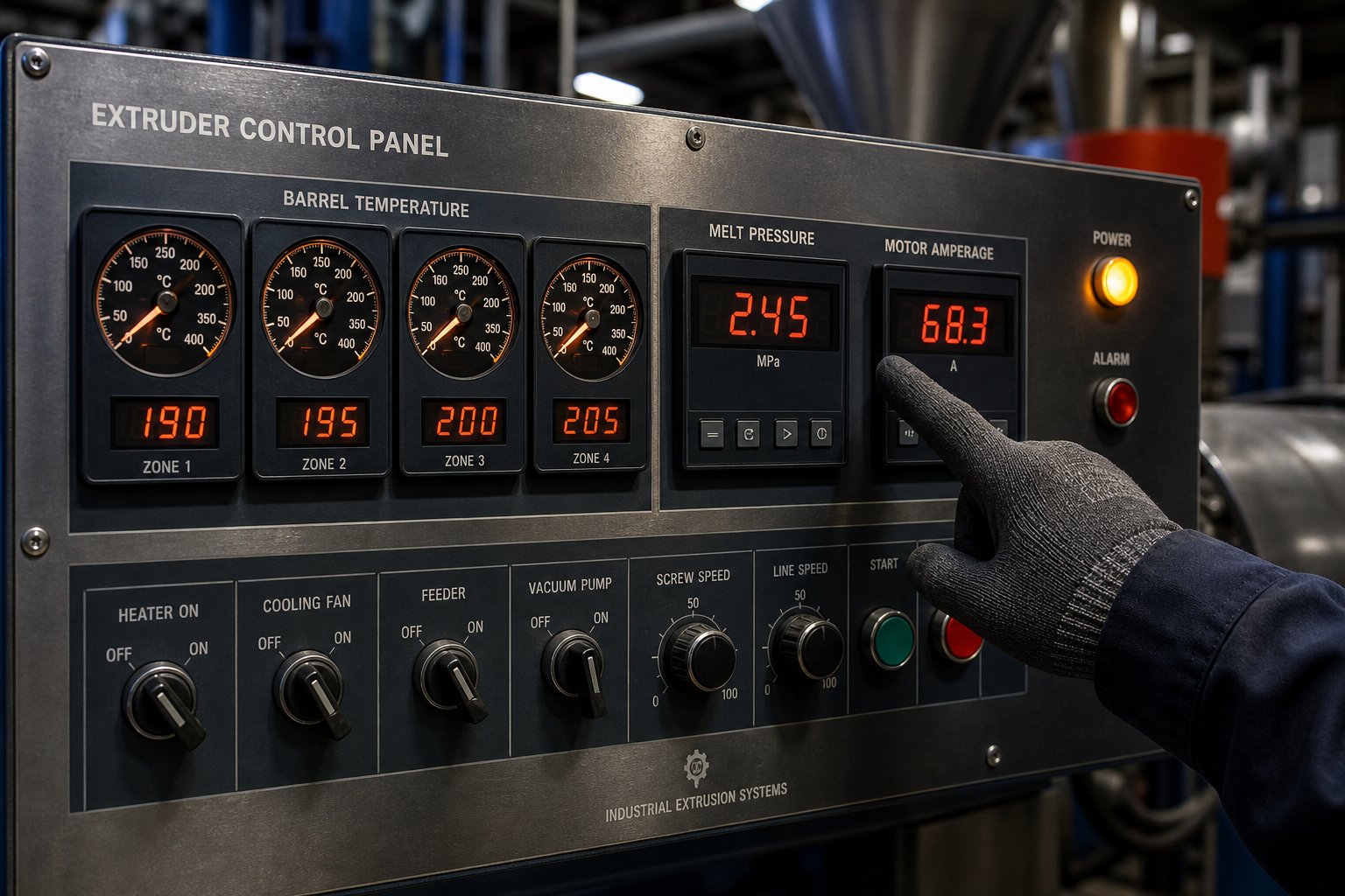
Turning Melt Temperature, Pressure, and Amperage Into Answers
Your extruder's instrument panel is constantly broadcasting diagnostic signals. The challenge isn't a lack of data — it's knowing what the data actually means. Three readings available on virtually every extrusion line — melt temperature, melt pressure, and motor amperage — can tell you more about what's happening inside that barrel than any visual inspection of the product. The trick is learning to read them not as isolated numbers but as interconnected clues that point toward a specific root cause.
Most operators glance at these instruments to confirm the numbers match set points, then move on. That's a missed opportunity. The real diagnostic value lies in trends — how readings shift over minutes, hours, or weeks — and in relationships between readings. A pressure rise paired with stable amperage tells a completely different story than a pressure rise paired with climbing amps. Understanding these patterns transforms raw data into actionable direction, so you can isolate the root cause faster using the diagnostic framework covered earlier.
Melt Temperature and What Deviations Reveal
Here's something many operators overlook: the temperature displayed on the barrel zone controller is not the actual melt temperature. Barrel zone set points reflect the temperature of the barrel wall at each heater zone, measured by thermocouples embedded in the barrel steel. The polymer flowing through those zones can be significantly hotter or cooler than what the display reads, depending on shear heating, throughput rate, screw design, and resin properties.
This distinction between melt temperature vs. barrel temperature in extrusion is critical. A melt thermocouple installed at the adapter or die entrance gives you a far more accurate picture of what the polymer actually experiences before it enters the die. If your line doesn't have one, installing an immersion melt thermocouple is one of the highest-value instrumentation upgrades you can make.
So what do melt temperature deviations tell you?
- Melt temperature rising above set point at constant screw speed: This often signals excessive shear heating — the screw is working the polymer harder than intended, possibly due to a high-viscosity resin lot, a worn screw with reduced flight clearance efficiency, or a restrictive screen pack. As extrusion researchers have documented, screw wear increases discharge temperature because the growing flight clearance reduces heat-transfer efficiency at the barrel wall, forcing compensatory speed increases that generate even more shear heat.
- Melt temperature dropping below expected range: This could indicate a heater band failure on one or more zones, reduced throughput that lowers shear input, or a resin with different thermal properties than the previous lot. Check heater duty cycles — if a zone's heaters are running at 100% and the zone still can't reach set point, the heater band is likely failing or has already failed.
- Melt temperature fluctuating cyclically: Periodic swings often correlate with surging — inconsistent solids conveying or melt delivery by the screw. They can also result from a malfunctioning temperature controller cycling between heating and cooling without settling.
The key insight is that a single barrel zone temperature reading is just a data point. The relationship between all zones over time — and the gap between barrel set points and actual melt temperature — is where the diagnostic intelligence lives.
Melt Pressure Trends as Early Warning Signals
If you could monitor only one instrument on your extruder, melt pressure should be the one. Head pressure — measured at the adapter between the barrel outlet and the die — integrates the effects of material viscosity, screen pack condition, die restriction, and screw output consistency into a single number. Learning how to read melt pressure trends in extrusion is arguably the most valuable diagnostic skill an operator can develop.
Stable melt pressure under steady-state operation typically means the process is healthy. Industry benchmarks suggest that variation under approximately 50 PSI during steady-state running indicates a well-controlled process, though the acceptable range depends on the specific die, material, and screen pack configuration.
Deviations from that stability each carry distinct meanings:
- Gradually rising pressure over hours or shifts: This is the classic signature of screen pack loading. As contaminants — gels, carbon particles, filler agglomerates — accumulate on the screen mesh, resistance to flow increases steadily. The extruder compensates by building more pressure upstream of the restriction. Process engineers note that many processors grow accustomed to these gradual changes, compensating through operator adjustments rather than addressing the underlying filtration issue.
- Cyclic pressure fluctuations: Periodic pressure swings — rhythmic rises and falls — are the hallmark of surging. This can originate from inconsistent solids feeding (hopper bridging, material segregation, feed starvation), solid-bed breakup instability within the screw's transition section, or melt delivery pulsation. Extrusion pressure fluctuation causes and fixes often center on upstream material handling before the polymer even reaches the screw.
- Sudden pressure spikes: These typically result from contamination — a chunk of unmelt, a metal particle, or an agglomerate that temporarily blocks the screen pack or a flow channel. They can also indicate cold-start material slugs during improper startup sequences.
- Gradually declining pressure at constant screw speed: This is a more subtle signal. It can indicate screw or barrel wear that reduces the screw's pumping efficiency, or a decrease in material viscosity due to degradation or a resin lot change.
A practical diagnostic tip: if your line has pressure transducers both before and after the screen changer, monitor the differential between them. A growing pressure differential across the screen pack is one of the earliest and most reliable indicators that filtration capacity is diminishing — and that a screen change should be scheduled based on data rather than guesswork.
Motor Amperage and Drive Load Diagnostics
Motor amperage — or drive load percentage on newer systems — reflects the actual mechanical work the screw is performing. Think of it as a window into what's happening in the barrel's feed and transition zones, where the screw is compressing, conveying, and melting solid pellets. Extruder motor amperage troubleshooting reveals problems that temperature and pressure readings alone might miss.
- Sudden amperage spike: A sharp rise in amps often means the screw has encountered unexpected resistance — contamination in the feed, a slug of cold or unmelted material, or bridging in the feed throat. It can also indicate a foreign object (metal fragment, agglomerate) wedging between the screw flights and the barrel wall.
- Gradual amperage increase over weeks or months: This is a hallmark of progressive screw or barrel wear. As flight clearance increases, the screw's pumping efficiency drops. Operators compensate by running higher RPM to maintain throughput, which drives up the motor load incrementally. A detailed analysis by Spalding and Womer demonstrates that for a 100-mm screw running PE at constant rate, progressive wear forces screw speed increases that elevate both motor load and discharge temperature — a compounding problem that gradually erodes product quality and line profitability.
- Amperage dropping unexpectedly: This might seem like good news, but it can signal a loss of feeding — the screw is running but not doing full work because the feed section is starved. Check the hopper level, look for bridging, and verify the feed throat isn't plugged or overheated.
The real power of amperage data emerges when you track it alongside pressure and temperature. Individual readings can be ambiguous. Correlated patterns rarely are.
| Reading Pattern | Probable Cause | First Corrective Action |
|---|---|---|
| Pressure rising steadily + amps stable | Screen pack loading or die buildup restricting flow | Check screen pack differential pressure; schedule screen change if threshold exceeded |
| Pressure dropping + amps rising | Screw or barrel wear reducing pumping efficiency | Compare current output rate and melt temperature against documented baseline; schedule screw pull inspection |
| Pressure fluctuating cyclically + amps fluctuating | Feed inconsistency or solids conveying surging | Inspect feed throat for bridging; verify hopper level and blender operation; check for regrind size variation |
| Pressure stable + amps spiking suddenly | Contamination or cold material slug entering the screw | Check feed material for contamination or moisture; verify barrel zone 1 temperature and heater function |
| Pressure dropping + amps dropping | Feed starvation — screw running partially empty | Check hopper level and feed throat; look for material bridging or blocked feed opening |
| Pressure rising + amps rising + melt temp climbing | Viscosity increase from resin lot change or moisture in hygroscopic material | Verify material lot against spec sheet; check dryer operation and dew point for hygroscopic resins |
| Pressure stable + melt temperature gradually rising over weeks | Progressive screw wear increasing shear heating at higher compensating RPM | Document trend against baseline; plan screw pull at next scheduled downtime to measure flight clearance |
This table isn't a complete diagnostic manual — every extrusion line has its own personality based on screw geometry, resin type, and tooling configuration. But these patterns provide a reliable starting point that covers the majority of instrument-driven diagnoses operators encounter on the floor. When you train yourself to look at combinations rather than individual gauges, you'll often identify the root cause before the defect ever reaches the product — and that's the difference between catching a problem at the instrument panel and catching it at the scrap bin.
Instruments, however, only tell you what's happening inside the barrel and at the die. Many extrusion defects announce themselves visually — on the product surface, in its dimensions, or through contamination marks — long before instrument readings shift enough to trigger an alarm. Knowing how to connect what you see on the finished product to what's actually happening upstream is the next critical skill.
Identifying Visual Symptoms and Tracing Them to Root Causes
Your instruments can tell you a lot, but the product itself is the ultimate diagnostic surface. Operators on the floor don't start their mental troubleshooting from a pressure chart — they start from what they can see and touch at the end of the line. A rough texture, a warped edge, a dark speck embedded in the surface. Each visual symptom is a signal, and learning to read those signals accurately is what separates a ten-minute fix from a two-hour scrap marathon.
The key is organizing your response around the defect you observe, then tracing it backward through the process chain. Below is a scannable reference — structured so you can identify what you're looking at, understand where it likely originates, and know what to check first.
Surface Defects From Shark Skin to Die Lines
Extrusion surface defects causes and solutions tend to cluster around a handful of recurring problems. Surface flaws are usually the first thing operators notice because they're visible immediately as the product exits the die or reaches the haul-off. Here's what each one looks like, where it comes from, and your best first move.
- Sharkskin (melt fracture at die lips): The product surface shows a rough, ridged, or cracked texture — sometimes described as a fine sawtooth pattern. This happens when the polymer experiences excessive shear stress at the die exit, exceeding the melt's critical stress threshold. High-molecular-weight resins are especially prone to it. First action: Increase die temperature to reduce melt viscosity at the die lips, or reduce extrusion speed. If neither helps, consider a processing aid or a resin with better melt flow characteristics.
- Melt fracture (severe): When sharkskin escalates, you'll see gross distortion — a surface that looks wavy, spiraling, or completely irregular rather than just rough. This is severe melt fracture driven by melt velocity exceeding what the die geometry can handle smoothly. First action: Lower screw RPM to reduce throughput rate through the die, and raise the die zone temperature. If the problem persists, the die land length or entry angle may need evaluation.
- Die lines: These appear as continuous, parallel streaks running in the machine direction along the product surface. They're typically caused by scratches, nicks, or material buildup on the die land or lip surface. Even a tiny imperfection on the die land will telegraph itself onto every meter of product. First action: Inspect and clean the die lips. If cleaning doesn't resolve the lines, the die land needs polishing. Check for carbonized material lodged in flow channels.
- Orange peel texture: The surface has a dimpled, textured appearance resembling citrus skin. This usually results from a mismatch between melt temperature and cooling rate — the surface freezes before the melt beneath it has stabilized, creating micro-wrinkles. It can also indicate insufficient melt homogeneity. First action: Adjust the cooling rate (slow it down if quenching too aggressively) or raise the melt temperature slightly to improve surface flow before solidification.
- General surface roughness: A dull, uneven finish without a specific pattern. This can stem from inadequate die temperature, contamination on the die face, or running a resin at the low end of its processing window. First action: Verify die temperature is within the recommended range for the resin, clean the die face, and confirm the material is within specification.
If you want to understand how to fix shark skin melt fracture in extrusion, the common thread across these surface defects is the relationship between polymer viscosity at the die and the shear rate imposed by throughput and die geometry. Adjustments that reduce shear stress at the die exit — higher die temperature, lower output rate, streamlined die design — address the majority of surface issues.
Dimensional and Structural Defects
Dimensional problems are sneakier than surface flaws. A profile might look perfect at the die but arrive at the saw or winder with wall thickness variation, bowing, or internal voids that only show up during quality checks. These defects often originate in melt distribution, cooling uniformity, or screw output consistency — and they can involve the downstream half of the line just as much as the extruder itself.
- Uneven wall thickness: One side of a pipe, profile, or sheet is consistently thicker or thinner than the other. Common root causes include uneven die gap distribution, temperature gradients across the die head, or a misaligned mandrel in pipe and tubing dies. Cooling asymmetry downstream — one side of a tank running warmer than the other — can also pull dimensions off-center. First action: Measure the die gap around its circumference. If the gap is even but the product isn't, check for uneven die temperature or asymmetric cooling. Verify that the calibration sleeve or vacuum tank is centered.
- Warpage: The finished product bows, twists, or curves after exiting the line. Extrusion warpage and uneven wall thickness causes overlap significantly — both frequently trace back to uneven cooling that locks in differential shrinkage across the cross-section. Semi-crystalline materials like polyethylene and polypropylene are particularly sensitive because crystallization rate varies with cooling rate. First action: Check for cooling uniformity on all sides of the product. Adjust water flow, spray positions, or air cooling to equalize the cooling rate. If warpage only appears after the product leaves the line, verify that it's being supported properly during post-extrusion cooling.
- Voids and bubbles: Internal cavities visible in cross-section cuts, or bubbles that distort the product surface. These typically result from moisture in the raw material, entrapped air during feeding, or volatile gases released from overheated additives. Excessive die temperature or too much lubricant in the formulation can also generate gas. First action: Verify the material has been properly dried — especially hygroscopic resins like nylon, PET, or polycarbonate. Check the feed throat for air leaks. If using vented extrusion, confirm the vacuum vent is functioning and not plugged.
- Inconsistent cross-section dimensions: Dimensions that fluctuate cyclically rather than drifting in one direction. This pattern points to surging — periodic variation in screw output — rather than a static die or cooling issue. It can also result from unstable haul-off speed or inconsistent vacuum calibration. First action: Monitor head pressure for cyclic fluctuations. If pressure is surging, the cause is upstream in the extruder (feed inconsistency, solids conveying problems). If pressure is stable but dimensions still vary, investigate downstream — haul-off speed stability, vacuum level consistency, or cooling water flow rate.
Contamination and Degradation Symptoms
Some of the most alarming visual defects — black specks, discolored streaks, embedded particles — fall into the contamination and degradation category. Distinguishing between these two sources matters because the corrective actions are fundamentally different. Material-source contamination requires upstream changes (material handling, storage, incoming quality). Process-induced degradation requires adjustments to residence time, temperature, or equipment cleaning.
- Gels and fish eyes: Small, raised bumps or translucent spots on the surface — sometimes with a visible boundary ring. Gels are typically cross-linked polymer fragments or foreign material that didn't melt properly during processing. Fish eyes specifically appear as small circular defects, often with a white or opaque center, caused by contamination with an incompatible polymer or by moisture in hygroscopic resins. First action: Check the material for contamination — are different resins being stored or handled near each other? Verify dryer performance for moisture-sensitive materials. If gels are recurring, inspect the screw and die for stagnation zones where material can sit and degrade. Increase screen mesh fineness to catch gels before they reach the die.
- Black specks and gels in extruded product: Dark particles embedded in the product, ranging from pinpoint spots to larger flecks. Black specks are usually degraded polymer — carbonized material that has been sitting in a dead zone of the barrel, die, or adapter at elevated temperature for too long. They can also come from contaminated regrind or dirty raw material. First action: Purge the extruder thoroughly. If black specks persist after purging, the contamination source is likely a dead spot in the flow path — the die, adapter, or screen changer area. Disassembly and cleaning may be required. Review regrind quality and storage practices.
- Discoloration and yellowing: A general shift in product color — often yellowish or brownish — that indicates thermal degradation of the polymer. This is especially common with heat-sensitive resins like PVC, PET, and POM. Causes include excessive barrel or die temperatures, high shear from elevated screw speed, or extended residence time during low-throughput runs. First action: Reduce barrel and die temperatures, particularly in the metering and die zones. Lower screw speed if shear heating is suspected. If processing PVC or other temperature-sensitive materials, verify that heat stabilizer levels in the formulation are adequate.
- Burnt streaks: Dark, elongated marks that appear intermittently in the product — distinct from uniform discoloration because they come and go rather than being continuous. These indicate localized degradation, often from material trapped in a dead spot that periodically dislodges into the melt stream. A worn screw flight edge, a damaged die flow channel, or a poorly seated screen pack can all create pockets where polymer stagnates and chars. First action: Purge the system and observe whether the streaks flush out. If they recur, plan a teardown of the die, adapter, and screen changer to locate and eliminate the dead zone. Inspect the screw for worn flights or damaged mixing sections that could trap material.
Across all three categories, you'll notice a recurring theme: the defect you see on the product is rarely the problem itself — it's a symptom of an upstream condition. Surface issues point back to shear stress and die condition. Dimensional problems trace to melt distribution and cooling uniformity. Contamination symptoms lead to material handling or equipment cleanliness. The visual entry point gets you started, but the root cause almost always lives somewhere else in the line.
Some extrusion formats, though, introduce their own specialized defect modes that don't fit neatly into these general categories. Blown film is a prime example — bubble instability, gauge variation, and optical defects all demand their own diagnostic approach, built on the same principles but applied to a very different set of variables.
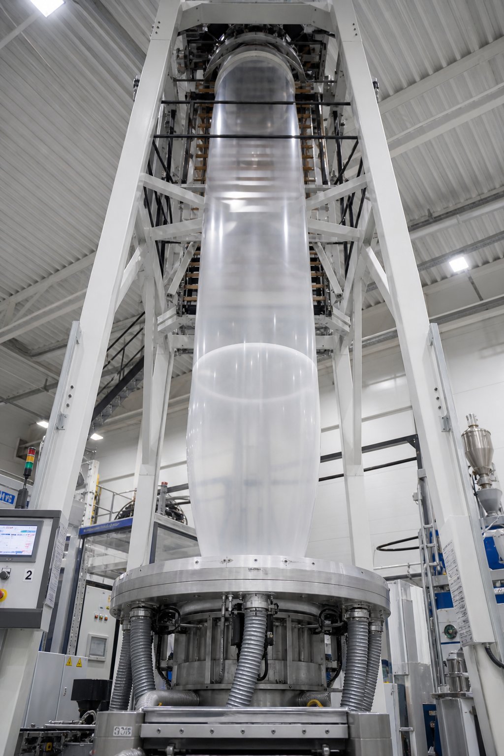
Blown Film Extrusion Defects and Targeted Corrections
Blown film lines operate under a unique set of physics. Unlike pipe or profile extrusion, where the product is shaped and constrained almost immediately after leaving the die, blown film relies on a free-standing molten bubble — inflated by internal air pressure, cooled by an external air ring, and stretched simultaneously in two directions before it solidifies. That combination of forces creates defect modes you simply don't encounter in other extrusion formats, and it demands a dedicated blown film extrusion troubleshooting guide built around what operators actually see on the tower.
The diagnostic framework from earlier chapters still applies — observe, record, isolate, test, verify. But the variables are different here. Bubble geometry, air ring performance, frost line behavior, collapsing frame alignment, and winder tension all interact in ways that can make a single defect look like it has five possible causes at once. The key is knowing where to look first.
Bubble Instability and Gauge Variation
If the bubble isn't stable, nothing else matters. Bubble instability is the most disruptive issue on a blown film line because it cascades into almost every other quality metric — thickness uniformity, optical properties, and mechanical performance all suffer when the bubble oscillates, helically rotates, or breathes in and out during production.
What does instability actually look like? You might see the bubble swaying side to side, spiraling as it rises, or pulsing rhythmically in diameter. Sometimes the frost line — that visible boundary where the melt transitions from transparent to opaque — rides up and down or tilts unevenly around the circumference. Any of these patterns signal that the balance between internal air pressure, external cooling, and melt delivery has broken down.
Common causes include:
- Uneven cooling airflow: An air ring that isn't centered on the die, has partially blocked ports from dust or resin buildup, or delivers asymmetric airflow will push the bubble off-center and trigger oscillation. External drafts from open doors, overhead ventilation, or nearby equipment can produce the same effect.
- Die temperature non-uniformity: If one side of the die runs hotter than the other, the melt viscosity varies around the circumference. The hotter, lower-viscosity side stretches more easily, creating a thinner wall and a bubble that leans toward the cooler side.
- Inconsistent melt delivery: Surging from the extruder — cyclic fluctuations in output rate — causes the bubble diameter to pulse. You'll often see this as periodic gauge bands in the machine direction that correlate with pressure variations within the system.
- Incorrect BUR or internal air pressure: Running the blow-up ratio at the edge of the resin's processing window makes the bubble hypersensitive to minor disturbances. Too much internal pressure stretches the bubble beyond its stable zone; too little produces a limp, wandering tube.
Gauge variation — inconsistent film thickness across the width or around the circumference — is closely linked to bubble stability, but it can also exist independently. You might have a perfectly stable bubble that still produces film with persistent thick and thin lanes. As gauge control specialists point out, this variation is not random — it typically results from a combination of mechanical, thermal, and cooling factors that can be identified and improved.
How do you determine whether a gauge problem is die-side or air-ring-side? Here's a practical approach: if the thick and thin bands remain in fixed positions relative to the die (they don't move even when you rotate the die or oscillate the haul-off), the problem almost certainly originates in the die gap or die temperature. If the bands shift position, follow the airflow, or change character when you adjust cooling, you're looking at an air ring issue. Many operators reach for the die bolts as their first move, but experienced troubleshooters recommend confirming air ring alignment and cleanliness first — it's faster, lower-risk, and catches the most common causes before you introduce new variables by adjusting die gap.
Optical and Mechanical Film Defects
Bubble stability and gauge uniformity are the big-ticket items, but blown film operators also deal with a range of optical and mechanical defects that affect product quality and customer acceptance. These issues often originate somewhere other than where they first appear — and that's what makes them tricky.
- Haze: Film that should be clear comes out cloudy or milky. Blown film haze and gel defects causes frequently trace back to cooling rate. Insufficient cooling airflow allows the polymer to crystallize more slowly, scattering light and reducing clarity. Resin selection also plays a significant role — the same process settings can produce acceptable clarity with one grade and unacceptable haze with another. First action: Increase cooling air volume and verify the air ring is delivering uniform flow. If haze persists, check the resin grade's optical specifications and confirm melt temperature is appropriate for the material.
- Gels in film: Small raised bumps or fish eyes embedded in the film surface. These are cross-linked polymer fragments, degraded material, or contamination that passed through the screen pack without being caught. In blown film, gels are especially problematic because they create weak spots that can initiate tears during converting or end-use. First action: Increase screen mesh fineness, inspect the extruder for dead spots where material can stagnate, and verify regrind quality if reclaimed material is being blended.
- Draw resonance: A periodic, rhythmic variation in film thickness in the machine direction — almost like the film is pulsing as it stretches between the die and the frost line. This occurs when the extensional flow of the melt becomes unstable, typically at high draw-down ratios or with resins that have low melt strength. First action: Reduce haul-off speed to lower the draw-down ratio, or increase melt temperature slightly to reduce extensional viscosity. If the problem persists, consider a resin with higher melt strength.
- Wrinkles at the nip or winder: The film looks fine on the bubble but develops creases, folds, or wrinkles as it passes through the collapsing frame and nip rollers. This is a downstream mechanical issue — poor web alignment, uneven tension, or incorrect collapsing frame setup are the usual culprits. Misaligned nip rollers compress the film unevenly, locking wrinkles into the layflat. First action: Check collapsing frame geometry and nip roller alignment. Verify that web tension is consistent and not fluctuating with winder roll buildup.
The critical takeaway for blown film is that many defects that appear to originate at the die actually have downstream roots — and vice versa. A winder that gradually changes tension as the roll diameter increases can feed oscillations back through the haul-off and into the bubble itself. A gauge variation that looks like a cooling problem might actually be driven by melt supply instability from a loading screen pack. You need to check the entire line, from extruder output through the collapsing frame and winder, to avoid chasing a symptom in the wrong zone.
The following table maps common blown film defects to their most likely upstream and downstream causes, giving you a structured starting point for diagnosis:
| Defect Observed | Check First (Upstream) | Check Second (Downstream) | Common Fix |
|---|---|---|---|
| Bubble oscillation or helical instability | Melt temperature uniformity around die; extruder output consistency (head pressure stability) | Air ring centering and airflow balance; ambient drafts near the tower | Center and clean the air ring; eliminate external drafts; stabilize extruder output |
| Persistent gauge bands (fixed position) | Die gap concentricity; die temperature uniformity; die lip condition | Air ring port blockage or uneven airflow distribution | Confirm air ring alignment first; adjust die bolts only after cooling is verified uniform |
| Gauge drift over time | Screen pack loading (rising melt pressure); resin lot viscosity change | Haul-off speed drift; winder tension feedback | Monitor melt pressure trend; schedule screen change based on pressure differential |
| Haze or reduced clarity | Melt temperature too low or too high for resin; inadequate mixing | Insufficient or uneven cooling airflow at the air ring | Optimize air ring volume and distribution; verify melt temperature is in resin's clarity window |
| Gels or fish eyes in film | Degraded material in barrel dead zones; contaminated regrind; insufficient screen filtration | Not typically downstream — gels originate upstream | Increase screen mesh fineness; purge extruder; inspect and clean die flow channels |
| Draw resonance (periodic MD thickness pulsing) | Excessive draw-down ratio; low melt strength resin; melt temperature too low | Haul-off speed set too high relative to extruder output | Reduce haul-off speed; raise melt temperature; consider higher melt strength resin grade |
| Wrinkles at nip or on wound roll | Gauge variation feeding uneven layflat into the collapsing frame | Collapsing frame misalignment; nip roller pressure imbalance; winder tension variation | Align collapsing frame and nip rollers; stabilize winder tension control; address upstream gauge variation if present |
| Edge curl or baggy edges | Uneven melt flow distribution across die width | Asymmetric cooling or collapsing geometry; uneven web tension across the film width | Check die temperature profile; adjust air ring for edge cooling; verify collapsing frame symmetry |
You'll notice a pattern in this table: the upstream check almost always involves melt quality and die condition, while the downstream check focuses on cooling, tension, and mechanical alignment. When you're troubleshooting blown film, working through both columns before making changes prevents the common mistake of fixing a symptom in one zone while the actual cause sits in the other.
Blown film defects highlight something that applies across all extrusion formats — the product you see at the end of the line is shaped by every piece of equipment it passes through. But there's one component that sits at the heart of every extrusion process, upstream of everything else, and its influence on defect formation is often underestimated: the screw and barrel themselves. When their geometry doesn't match the resin or when wear silently degrades their performance, even perfectly tuned downstream equipment can't compensate.
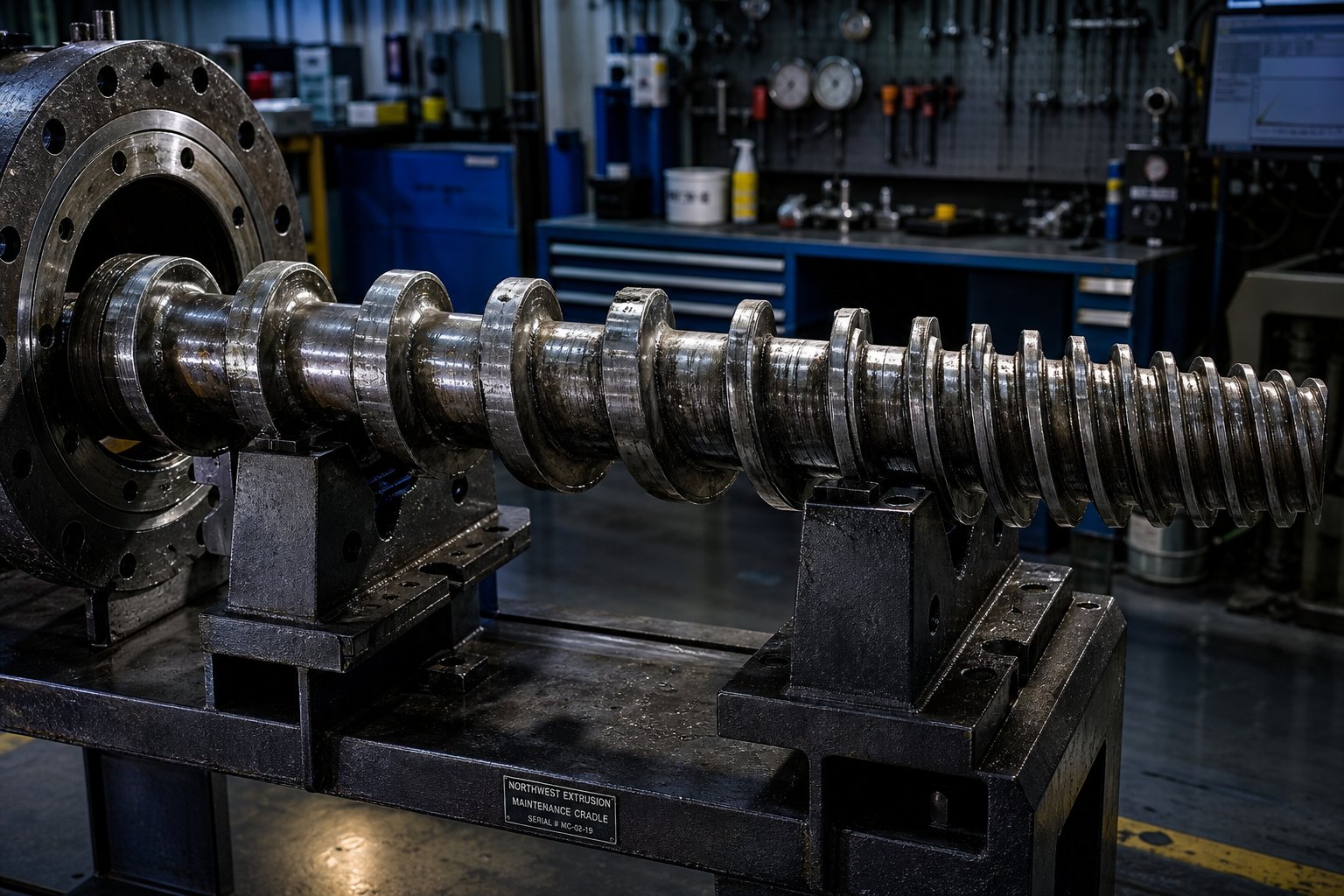
Screw and Barrel Geometry as a Hidden Source of Defects
Every chapter so far has traced extrusion defects back through process settings, die conditions, cooling equipment, and material properties. But there's a component sitting upstream of all those variables — one that quietly determines melt quality before the polymer ever reaches the die — and it rarely gets the diagnostic attention it deserves. The screw and barrel are the heart of your extruder, and their geometry directly controls how the polymer melts, mixes, and pressurizes. When that geometry is wrong for the resin — or when it silently degrades through wear — the symptoms show up everywhere downstream, disguised as process problems that no amount of temperature or speed adjustment can permanently fix.
Understanding how screw compression ratio affects extrusion quality is essential for any operator or engineer who wants to move beyond surface-level fixes. The screw isn't just a conveyor. It's a precisely engineered melting machine, and its design parameters — compression ratio, L/D ratio, flight depth transitions, and mixing section geometry — each influence a specific aspect of melt formation. Get any one of them wrong, and you'll chase defects that seem to resist every corrective action you throw at them.
How Compression Ratio and Flight Geometry Affect Melt Quality
Compression ratio is the relationship between the channel depth in the feed zone and the channel depth in the metering zone. It determines how aggressively the screw compresses the solid polymer as it transitions into a melt. Think of it as the screw's "squeeze factor" — too much compression for a given resin and you generate excessive shear, overheat the polymer, and risk degradation. Too little compression and the material doesn't fully melt or homogenize, producing gels, unmelt specks, and viscosity inconsistencies that cascade into every downstream defect category we've discussed.
Here's where it gets practical. A general-purpose screw with a moderate compression ratio might perform adequately across several commodity resins, but as screw design specialists emphasize, it often falls short with high-performance, filled, or heat-sensitive materials. A screw designed for HDPE, with its semi-crystalline structure and relatively high melting energy requirement, will behave very differently if you start running LLDPE or PP through it. The compression ratio that produced a clean, stable melt with one resin can cause surging, overheating, or poor mixing with another.
Several geometry factors interact with compression ratio to shape the melt:
- L/D ratio (length-to-diameter): A longer screw relative to its diameter provides more residence time and more opportunity for energy input. Standard single-screw extruders typically range from 24:1 to 36:1 L/D. Shorter L/D ratios limit the available melting and mixing length, making compression ratio selection even more critical because the screw has less room to complete the melt transition.
- Flight depth transitions: How gradually or abruptly the channel depth decreases from the feed section through the transition zone to the metering section controls the rate of pressure buildup and shear introduction. A steep transition concentrates mechanical energy in a short zone, which can cause localized overheating or solid-bed breakup — a known trigger for surging and cyclic output variation.
- Mixing section design: Once the polymer is molten, mixing elements — Maddock-style, spiral, or dispersive geometries — refine temperature uniformity and blend quality. As melt quality research confirms, these sections aren't melting devices but conditioning tools that finalize the melt before it enters the die. Without adequate mixing, temperature gradients and poorly dispersed additives pass straight through to the product as haze, color streaks, or mechanical weak spots.
The critical point is this: a screw that was perfectly matched to your process five years ago may no longer be the right geometry if you've changed resins, throughput targets, or product specifications. And even if nothing has changed in your process recipe, the screw itself is changing — slowly, silently, and inevitably — through wear.
Recognizing When the Screw or Barrel Is the Root Cause
This is where screw and barrel troubleshooting for extruders gets tricky. Wear doesn't announce itself with a dramatic failure. It creeps in over weeks and months, gradually shifting your process baseline so slowly that operators compensate without realizing they're masking a hardware problem with process adjustments.
Imagine this scenario: your line has been running the same resin for months, but you've noticed you need slightly higher screw speed to hit target output. Melt temperature has drifted up a degree or two at the same set points. Motor amps are a bit higher than they were six months ago. Product quality is still acceptable — barely — but you're making more frequent small adjustments to keep it there. Each of these shifts is individually subtle enough to dismiss. Together, they're the unmistakable signature of progressive screw or barrel wear.
Research by Spalding and Womer illustrates this clearly: for a 100-mm diameter screw running 1 MI polyethylene at 150 kg/hr, as flight clearance increases from wear, the operator must increase screw speed to maintain constant output. That higher speed generates more shear heating, raising discharge temperature. For a blown film application, the discharge temperature increase at just 0.011 inches of flight wear could force a rate reduction of up to 13% to keep the process stable — a direct hit to line profitability and capacity.
The challenge is distinguishing between a process-setting problem and a hardware problem. Here are the telltale extruder screw wear symptoms and diagnosis indicators that point to worn screw or barrel geometry rather than a process adjustment issue:
- Gradually increasing melt temperature at the same RPM and barrel set points: As flight clearance grows, more material leaks back over the flights instead of being pumped forward. The screw has to work harder, and heat-transfer efficiency at the barrel wall drops because the melt film thickness over the flights increases. The result is a creeping discharge temperature that barrel cooling can't fully offset.
- Declining specific output rate: Specific rate — throughput divided by screw speed — is one of the most reliable signs of barrel wear in plastic extrusion. If you're running faster to get the same output, the screw is losing pumping efficiency. A new screw delivers a predictable output per revolution; a worn screw delivers less because material flows backward through the enlarged clearance.
- Rising motor amperage trend over weeks: Higher amps at the same screw speed means the drive is working harder. This can reflect increased drag from worn surfaces, higher viscosity from inadequate melting, or the need for higher RPM to compensate for pumping losses — all connected to geometry degradation.
- Increased sensitivity to process disturbances: A worn screw has less margin. Small changes in feed bulk density, resin lot variation, or ambient temperature that the screw previously handled without issue now produce visible product variation. The screw's ability to smooth out input inconsistencies depends on its compression and conveying efficiency — both of which erode with wear.
- Visible scoring, galling, or hard-facing loss on removed screws: When you pull the screw for inspection, look at the flight tips. The hard facing — typically about 0.060 inches thick when new — wears down with service. Once the hard facing is gone, the softer base metal wears rapidly. Industry guidelines suggest evaluating replacement when flight clearance reaches four times the original clearance, though critical applications like medical tubing may require action at just two times the original clearance.
- Barrel bore diameter increase: When the screw is out, measure the barrel's inside diameter at several points along its length. Iron-based bimetallic liners typically last about three screw service lives, but abrasive resins — glass-filled, mineral-filled, or high-calcium-carbonate compounds — can accelerate barrel wear dramatically. Uneven bore wear indicates alignment issues or localized side-force problems from solid-bed blockages.
A practical rule of thumb: if you've optimized every process variable and the problem persists, or if a problem that was "fixed" keeps returning after a few shifts, stop looking at your settings and start looking at your hardware. The screw and barrel are the one part of the process chain that changes physically over time, and no amount of temperature or speed adjustment can compensate for geometry that's drifted beyond its design tolerance.
When diagnosis confirms that worn or mismatched screw-barrel geometry is the root cause, the corrective path shifts from process adjustment to component replacement or redesign — and this is where getting the right components matters enormously. A replacement screw must be matched to the specific resin, product type, throughput target, and extruder model to restore the melt path the process was designed around. Off-the-shelf general-purpose screws may get a line running, but they rarely deliver the melt quality a tailored geometry provides. For extrusion manufacturers and recycling plants sourcing replacement screw barrels or custom screw designs matched to pipe, profile, film, sheet, WPC, or granulation applications, NANHAIYA's screw barrel support page offers a practical starting point for identifying components engineered for specific processing requirements.
Screw and barrel wear is a slow-motion problem — but the moments that inflict the most acute damage on equipment and product quality often happen fast, during the operational phases that most facilities pay the least attention to: startup, shutdown, and material transitions.
Startup, Shutdown, and Material Transition Problems
A screw that's been silently wearing down will punish you over months. But a botched startup or a careless shutdown can ruin your next production run in minutes. These transitional phases — starting up, shutting down, switching materials — are where some of the most stubborn extrusion defects originate, yet they rarely appear in any formal troubleshooting guide. Operators learn them through tribal knowledge, handed down shift to shift, often inconsistently. The result? Black specks that appear out of nowhere on Monday morning. Pressure spikes that crack a screen pack before the first good product reaches the puller. Color contamination that lingers for hours into a new run. Every one of these problems traces back to how the line was stopped, started, or transitioned — not to steady-state process settings.
Startup Sequences That Prevent Early Scrap
Rushing startup is the single fastest way to fill your scrap bins before production even begins. The most critical element of any extruder startup procedure to reduce scrap is heat soak time — the period after barrel heaters reach set point but before you turn the screw. Why does this matter? Because barrel zone controllers only measure wall temperature. The polymer sitting inside the barrel — left from the previous run — needs time for heat to conduct from the barrel wall inward through the full melt channel. If you start the screw before the material is uniformly molten, you'll push cold slugs and partially melted pellets downstream into the screen pack and die.
The consequences are immediate and expensive:
- Cold slugs wedge against the breaker plate and screen pack, causing sudden pressure spikes that can rupture screens or damage the die.
- Unmelted pellets pass through into the product as visible inclusions, or jam in narrow die flow channels.
- Pressure spikes stress the head hardware and can blow seals if bolts aren't properly torqued.
Davis-Standard's maintenance guidelines emphasize that bringing the line to startup condition at a temperature lower than normal operating temperature — then heat-soaking until the material is completely molten — produces a cleaner, safer restart. The higher viscosity of the cooler polymer creates scrubbing forces against the barrel and screw surfaces, assisting with purging residual material from the previous run. The size of your extrusion system directly affects the required soak time: larger barrels and dies need proportionally longer soaks because heat must penetrate deeper into the metal mass.
A practical startup sequence looks like this: bring all zones to soak temperature, wait the manufacturer's recommended soak time (typically 30 to 90 minutes depending on extruder size), then start the screw at low RPM — no more than 10 to 15 RPM — and gradually ramp up speed while monitoring head pressure and motor amps. Watch for pressure stabilization before increasing to production speed. Patience here saves material, protects equipment, and prevents the kind of contamination that haunts the first hour of a run.
Shutdown Procedures That Protect Equipment
If startup damage is immediate, shutdown damage is delayed — and that makes it sneakier. A proper shutdown sequence for plastic extrusion protects not just the current shift but the next one. The core risk during shutdown is leaving heat-sensitive resin sitting in a hot barrel, where it degrades, oxidizes, and carbonizes into the very black specks and burnt streaks we diagnosed in earlier chapters.
The key to a successful shutdown, as industry practice recommends, is purging the current production resin — while still at operating temperature — with a more thermally stable material introduced at a lower temperature. This achieves two things: it displaces the reactive production resin with something that won't degrade during the cooling period, and it reduces the barrel temperature gradually rather than trapping hot polymer in a system that's about to sit idle.
What happens when you skip this step? The production resin stays in contact with hot barrel walls as the system cools. Oxygen permeates through the hopper and feed throat. The combination of heat, residence time, and oxygen causes degradation — especially severe with PVC, PET, POM, and other temperature-sensitive resins. The degraded material bakes onto the screw root, flight edges, and barrel wall, forming a carbon layer that flakes off unpredictably during the next startup. Veteran extrusion engineer Allan Griff notes that even a more stable shutdown purge won't prevent every problem — old, degraded melt left in flow channels can still produce sprays of gels and fish eyes when production resumes if the barrel isn't adequately cleaned.
Additional shutdown considerations that protect equipment for the next run:
- Run the screw at low RPM after cutting heater power to push melt temperature down and reduce thermal exposure time for any remaining polymer.
- Cut off hopper flow before stopping the screw — use a slide plate to seal the feed throat, then run a few more seconds to clear the first flights. This prevents bridging in the throat and sticking to the screw root in the feed zone during cooling, which can complicate the next restart.
- Keep barrel cooling on for several minutes after the screw stops to prevent residual heat from soaking further into the polymer and accelerating degradation.
- Protect die lips with a non-scratching, non-melting cover to prevent damage and oxidation during downtime.
- If disassembling the head and die, work fast as a team — plastic comes off easier when hot, and the first 10 to 15 minutes after stopping are critical before the polymer hardens and degrades further.
Every improper shutdown plants a time bomb for the next startup. Carbon buildup from degraded resin lodges in screen packs. Oxidized material slugs sit in dead zones of the adapter or die. These contaminants don't always flush out with a simple purge — they dislodge unpredictably during production, producing intermittent black specks that operators can spend hours trying to diagnose when the real cause was how the line was shut down two days earlier.
Transition Troubleshooting Between Materials or Products
Material transitions — color changes, resin switches, die changes — combine the challenges of both shutdown and startup into a single window where scrap rates peak. Knowing how to minimize waste during extrusion material changes requires planning, sequencing, and discipline. The biggest mistake is treating transitions as something to rush through rather than something to engineer.
A few principles apply broadly. Follow light colors with dark whenever scheduling allows — purging dark pigment out of a system is far harder than purging light pigment. Similarly, follow easy-flow melts with more viscous ones, since a higher-viscosity resin creates scrubbing forces that help displace the previous material. Of course, production scheduling doesn't always permit the ideal sequence. When you must go dark-to-light or switch between incompatible materials, a purpose-built purge compound — rather than just running the next production resin through — significantly reduces transition time and contamination risk.
For extrusion color change and resin transition tips that operators can apply consistently, follow this sequenced checklist:
- Prepare the new material in advance — pre-dry if required, stage it at the machine, and have a container ready for the hopper's existing contents.
- Record baseline process conditions before starting the transition — zone temperatures, screw RPM, head pressure, and motor amps — so you have a reference for the new material's setup.
- Reduce screw speed and empty as much of the current material from the hopper as possible.
- Introduce purge compound (or the new production resin if materials are compatible) and run at moderate speed until the extrudate shows no trace of the previous material or color.
- Adjust temperature profiles to match the new resin's processing window before ramping to production speed — don't run the new material at the old material's settings.
- Ramp screw speed gradually while monitoring head pressure and melt temperature for stability.
- Inspect the first product carefully for contamination, color streaks, or off-spec dimensions before committing to full production.
- Document the transition — what worked, how much purge material was used, how long it took, and any issues encountered — so the next operator can replicate the procedure.
That last step deserves emphasis. A transition that took one operator twenty minutes and two kilograms of purge should take the next operator roughly the same — but only if the procedure is written down. Undocumented transitions are reinvented from scratch every time, with inconsistent results across shifts. Changeovers handled inconsistently from shift to shift are one of the most common sources of ongoing contamination in sheet, film, and profile operations. Building transition procedures into standardized work instructions eliminates the variability and makes scrap reduction repeatable rather than dependent on who happens to be running the machine.
Startup, shutdown, and transition procedures all share something in common: they put operators in close physical contact with hot equipment, open dies, pressurized melt, and moving machinery under time pressure. That combination — urgency plus hazard — makes these phases exactly the moments when safety protocols matter most and are most likely to be bypassed.
Safety Protocols Every Operator Must Follow While Troubleshooting
Urgency is the enemy of safety on an extrusion floor. When scrap is piling up, the line is down, and a supervisor is asking for an ETA on the fix, the temptation to skip a lockout step, reach past a guard, or crack open a die head without fully depressurizing the system becomes very real. That's precisely why extrusion safety during troubleshooting procedures can't be treated as a separate checklist taped to a wall somewhere — it has to be embedded in the diagnostic framework itself. Every observation, every test, every corrective action from Step 1 through Step 5 should carry an implicit safety gate: can I perform this action without exposing myself or someone else to harm?
The phases we just covered — startup, shutdown, material transitions — are peak hazard windows. But troubleshooting during a live production run introduces its own dangers, because operators are interacting with hot, pressurized, moving equipment while simultaneously trying to think analytically. That dual cognitive load is where shortcuts happen. Here's how to prevent them.
Lockout Tagout and Safe Access During Die and Screen Changes
When your diagnostic process points to a screen pack that needs changing, a die that needs inspection, or a feed throat that requires clearing, you've crossed from process adjustment into physical interaction with hazardous energy sources. That boundary demands lockout/tagout (LOTO) procedures as defined under OSHA's 29 CFR 1910.147 — and there are no troubleshooting exceptions to this requirement.
OSHA's standard is clear: before placing hands or other body parts into a potentially hazardous machine area — whether to install, remove, adjust, clean, or repair components — energy must be isolated and controlled. The standard explicitly addresses the temptation to rely on control-circuit devices like inch modes or jog buttons as substitutes for full energy isolation during servicing. They aren't substitutes. An inch mechanism protects against hazards associated with press component motion during testing or positioning, but it does not protect employees from hazardous energy exposure during servicing and maintenance activities. Full LOTO is required.
What does this look like in practice on an extruder? When you need to open a die assembly, change a screen pack, or access the feed throat area:
- De-energize the drive system completely — don't just stop the screw and leave the motor powered. Apply your personal lockout device to the main disconnect and verify zero energy by attempting to restart.
- Isolate barrel heaters before working near heating zones. Even with the screw locked out, energized heater bands can cause severe burns on contact and create thermal hazards during die disassembly.
- Relieve residual melt pressure before loosening any bolts on the die, adapter, or screen changer. Trapped pressure in the head can release violently when a flange seal breaks, ejecting hot polymer at high velocity. Crack bolts gradually and in a controlled pattern — never remove one side completely while the other remains tight.
- Verify interlocks are functional before and after any troubleshooting intervention. Industry safety guidance requires that guard interlocks be maintained in working order and that presses failing safety requirements be locked out and removed from service until repaired.
- Communicate your lockout status to all nearby personnel — especially across shift changes. A lock without communication is half a safeguard. Every person working on or near the machine must know it's under active lockout and who holds the key.
Time pressure makes every one of these steps feel like an obstacle. An operator who has already diagnosed the likely cause — a loaded screen, a blocked flow channel — wants to get in, fix it, and get the line running again. Building LOTO into the diagnostic framework from Step 1 means accepting that the time required for safe access is part of the repair time, not an addition to it. Factor it into your estimate, communicate it to your supervisor, and never treat it as optional.
Handling Hot Polymer Melt and Ventilation Requirements
Molten polymer is one of the most dangerous materials on a production floor because it behaves unlike any other hot substance operators typically encounter. It doesn't splash like water — it sticks. Contact with skin causes deep, sustained burns because the polymer adheres to tissue and continues transferring heat long after initial contact. Scraping it off tears skin. Running cold water over it traps heat underneath the solidifying layer. There is no quick fix for a molten polymer burn, which is why prevention is the only acceptable strategy.
During troubleshooting, burn risk escalates in specific scenarios. Opening a die head or screen changer while residual pressure exists can cause jets of melted plastic to squirt out under high pressure — a hazard that intensifies if a blockage has created a pressurized pocket upstream. Clearing a plugged die lip or pulling a strand that's wrapped around a roller puts hands close to surfaces well above 200 degrees Celsius. Even routine purging sends molten material out the die exit at unpredictable angles.
Ventilation is the other half of the safe handling equation — and it's especially critical when processing PVC, fluoropolymers, or other resins that release hazardous fumes at processing temperatures. Fluoropolymer processing experts warn that vapors and fumes released during extrusion and die head cleaning can cause flu-like symptoms — chills, headaches, fever — that typically pass within 24 to 48 hours but indicate genuine chemical exposure. These corrosive gases must be captured immediately and removed with an exhaust ventilation system that includes extraction hoods placed directly above the die head. For PVC, thermal degradation releases hydrogen chloride gas, which is corrosive to both equipment and respiratory tissue. Extruder ventilation requirements for PVC processing demand continuous local exhaust ventilation at the die exit, the feed throat (where dust can become airborne), and any point where the melt is exposed to atmosphere.
Here are the critical safety rules specifically tailored to troubleshooting scenarios — distinct from general extrusion safety training because they address the unique hazards that arise when operators deviate from normal production to investigate and fix problems:
- Never loosen die bolts without full PPE — heat-resistant gloves, face shield, long sleeves, and closed-toe heat-resistant footwear. Assume trapped pressure exists until proven otherwise.
- Never bypass a guard interlock to observe a running process during diagnosis. If you need to see what's happening inside a guarded zone, shut the process down and lock it out first. No visual observation is worth an entanglement or crush injury.
- Never use compressed air to clear polymer fragments or plastic dust from surfaces — it creates airborne particulate that poses inhalation and explosion risks. Plastics dust can form explosive clouds, and blowing dust with compressed air is specifically identified as unacceptable practice.
- Never work alone during die or screen changes. A second person provides both physical assistance with heavy components and an immediate emergency response capability if a burn or pressure release occurs.
- Always verify ventilation is operating before purging or opening a hot die — especially after hours, on weekends, or during shutdown periods when building HVAC may be in reduced mode.
- Keep a clean water source and burn treatment supplies within arm's reach during any troubleshooting that involves contact with hot equipment or molten material.
- Report near-misses with the same urgency as actual incidents. A pressure release that missed an operator by inches is a system failure that needs investigation — not a lucky break to be shrugged off.
No troubleshooting fix is worth a safety incident — never bypass interlocks or guards to diagnose a running problem.
Safety isn't a step you add at the end of a troubleshooting sequence. It's the context in which every step occurs. An operator who builds safe access time into the diagnostic plan, wears appropriate PPE before the first bolt turns, and treats pressure relief as a mandatory prerequisite rather than a suggestion will troubleshoot just as effectively — and go home intact at the end of every shift. That consistency, applied day after day across every troubleshooting event, is what transforms reactive fixes into a sustainable, professional diagnostic practice — one that pairs naturally with the proactive maintenance and documentation habits that prevent many of these problems from occurring in the first place.
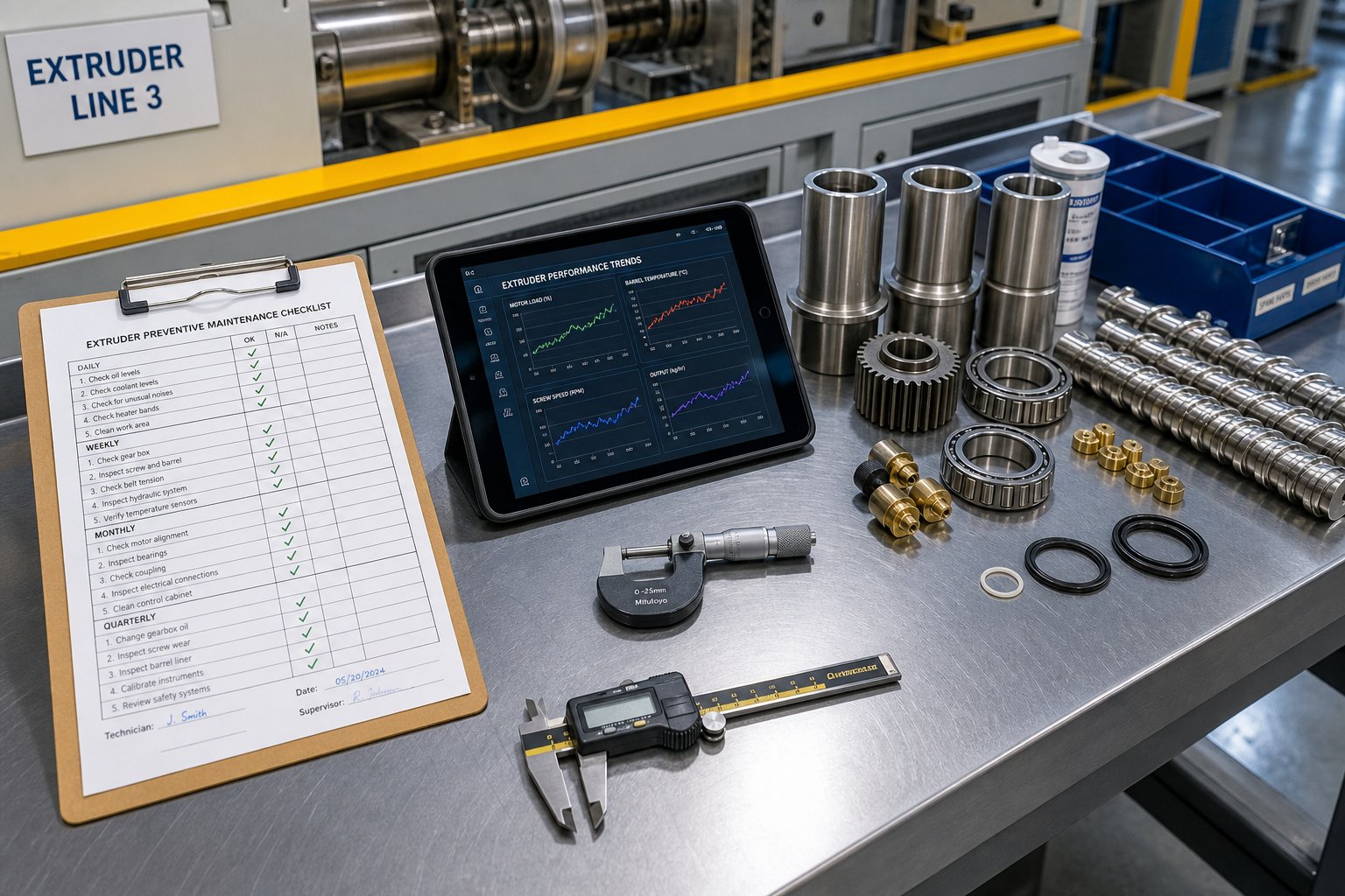
Proactive Maintenance and Documentation That Prevent Repeat Failures
Every chapter up to this point has focused on what to do when something goes wrong. But the most productive extrusion floors aren't the ones that troubleshoot fastest — they're the ones that troubleshoot least. The shift from reactive firefighting to proactive prevention hinges on two habits that most operations undervalue: documenting process data consistently, and scheduling maintenance based on measured wear trends rather than calendar dates or catastrophic failure. Together, these habits form the foundation of an extrusion preventive maintenance schedule template that actually reduces defect frequency over time instead of just checking boxes.
Think of it this way: every time an operator records a melt pressure reading during a good production run, they're building a diagnostic library. Every screw pull that measures flight clearance before it becomes a quality problem is a repair that happened on your schedule — not the machine's. The difference between planned maintenance and emergency downtime is data, and data only exists if someone writes it down.
What to Record and How to Communicate Extrusion Problems
Knowing how to document extrusion process problems effectively starts with capturing the right data points every shift — not just when something breaks. Consistent documentation enables pattern recognition across operators, shifts, and weeks. When a defect appears and the operator can compare today's readings against a documented baseline from the last three months, the root cause search narrows dramatically. When that documentation doesn't exist, every problem is diagnosed from scratch.
The following table outlines the essential data points every extrusion operation should capture routinely, where to find them, and why each one matters when a problem eventually surfaces:
| Data Point | Where to Read It | Why It Matters for Diagnosis |
|---|---|---|
| Melt temperature (each zone) | Barrel zone controller displays; immersion thermocouple at adapter or die entrance for actual melt temp | Establishes the thermal baseline; deviations reveal heater failures, shear heating changes, or resin lot shifts that trigger degradation or melt fracture |
| Head pressure | Pressure transducer at the adapter between barrel outlet and die | The single most informative reading — trends reveal screen loading, die buildup, viscosity changes, or screw wear before they cause visible defects |
| Screw RPM | Drive controller or HMI display | When correlated with output rate, reveals specific rate changes that signal pumping efficiency loss from screw or barrel wear |
| Motor amps (drive load %) | Motor drive panel or HMI trend screen | Reflects the actual work the screw performs; gradual increases over weeks indicate wear, while sudden spikes point to contamination or feed problems |
| Material lot number | Bag tags, delivery documentation, or material management system | Connects quality variations to specific resin batches; essential for isolating whether a defect is material-sourced or process-induced |
| Ambient temperature and humidity | Workshop thermometer/hygrometer or building management system | Seasonal and daily swings affect cooling capacity, feed throat behavior, and hygroscopic resin moisture uptake — often overlooked as a variable |
| Screen pack differential pressure | Pressure transducers upstream and downstream of the screen changer (if equipped); otherwise, head pressure trend alone | The most reliable indicator for scheduling screen changes based on actual filtration load rather than arbitrary time intervals |
| Defect description with time of onset | Operator observation — written in the shift log with a timestamp | Enables correlation between the defect and any process change, material transition, or equipment event that occurred at or before the same time |
The format matters almost as much as the content. A structured shift log with dedicated fields for each data point consistently captures more complete information than free-form notes. Industry research on shift documentation shows that templates with well-designed mandatory fields achieve 94% data completeness, compared to just 57% for minimally structured or free-text logs. Operators don't skip fields because they're careless — they skip them because poorly designed forms don't make the purpose of each entry obvious. Keep the documentation template short, specific, and clearly tied to the diagnostic value each data point provides.
When escalating a problem to engineering or maintenance, a documented record transforms the conversation. Instead of "the product looked rough on second shift," you can say: "surface roughness appeared at 14:20, melt pressure had risen 180 PSI above baseline over the previous four hours, amps were stable, and the screen pack had been running for 36 hours since the last change." That level of detail cuts diagnostic time in half because it immediately narrows the search to screen loading — not die temperature, not screw wear, not material contamination.
Building a Preventive Maintenance Schedule That Reduces Downtime
A maintenance checklist that only says "inspect the extruder" misses most of the equipment that actually causes production stops. Whole-line maintenance systems separate checks into daily, weekly, and monthly rhythms — each with a distinct purpose. Daily checks (10 to 15 minutes per shift) confirm the line is operating within its normal window: feed throat cooling flow, zone temperatures versus set points, melt pressure trend at a fixed screw speed, die lip condition, cooling water temperature, haul-off grip, and cutter timing. Weekly checks, performed during planned stops, target wear points: gearbox oil condition, heater band terminals, die bolt torque, water filter cleanliness, vacuum seals, and belt condition. Monthly checks focus on trend data — the numbers that reveal the direction of wear before it becomes a defect.
The most valuable monthly records include:
- Screw and barrel clearance measurements: Track flight-to-barrel clearance at the feed, transition, and metering sections during every screw pull. This is the core of any extruder screw pull inspection frequency and checklist — not pulling on a fixed calendar, but pulling when trend data (declining specific output, rising melt temperature, increasing amps) indicates geometry has drifted. Many operations schedule screw pulls annually, but abrasive compounds or glass-filled resins can demand inspections every three to six months.
- Screen pack change intervals based on pressure differential: Rather than changing screens every eight hours or every shift — a common but wasteful practice — monitor the pressure differential across the screen changer. Set a threshold (for example, a differential increase of 300 to 500 PSI above a clean-screen baseline, depending on your die and material) and change screens when data says they need it. This approach, as maintenance specialists emphasize, converts hidden drift into planned work — you schedule the change before the pressure rise causes visible product defects or forces a line stop.
- Thermocouple and heater band verification: A thermocouple that reads 5 degrees low doesn't trigger an alarm — it just makes the controller push the heater harder, which changes the actual melt temperature profile without anyone noticing. Verify thermocouple accuracy against a reference probe quarterly. Check heater band terminals for corrosion and wiring discoloration weekly; loose or corroded terminals create resistance that leads to inconsistent zone temperatures and eventual heater failure.
- Die maintenance and cleaning cycles: Die lip buildup, flow channel contamination, and land surface damage all accumulate gradually. Schedule die cleaning based on runtime hours and product inspection trends rather than waiting for die lines or streaks to appear in the product.
- Gearbox oil temperature and motor insulation resistance: Rising gearbox oil temperature under stable load suggests lubrication degradation or internal wear. Declining motor insulation resistance indicates moisture ingress or insulation breakdown. Both are slow-moving trends that predict catastrophic failures months before they happen — but only if you're measuring them regularly.
The thread connecting all of these maintenance activities is trend data. One pressure reading tells you the current state. Three months of weekly pressure readings tell you where the system is heading. As extrusion process data researchers have demonstrated, a data-acquisition system that captures and trends key variables over time is invaluable not just for detecting problems but for optimizing barrel temperatures, identifying feed instability, and verifying that corrective actions actually hold. If melt pressure, gearbox temperature, cooling delta-T, or screw clearance moves in the wrong direction for two or three consecutive readings, schedule the repair — before the line schedules it for you.
Proactive component replacement is the natural extension of trend-based maintenance. When screw pull data shows flight clearance approaching the replacement threshold, or when barrel bore measurements reveal progressive wear in the transition zone, waiting for a quality failure to force the issue means accepting the scrap, downtime, and secondary damage that come with it. Having a reliable supply partner for replacement screw barrels and custom extrusion components keeps preventive schedules on track instead of stalling while you source parts under emergency lead times. For extrusion manufacturers and recycling plants running pipe, profile, film, sheet, WPC, or granulation lines, NANHAIYA's screw barrel support page provides a practical resource for sourcing components matched to specific extruder models and processing applications — so that when your trend data says it's time to replace, the replacement is ready before the defect arrives.
Reactive troubleshooting will always be part of extrusion operations — materials surprise you, equipment ages, and processes drift in ways no maintenance schedule can fully prevent. But every problem you prevent through documentation and scheduled maintenance is a problem that never consumes operator time, never fills a scrap bin, and never risks a safety incident. The five-step diagnostic framework, the instrument reading patterns, the visual symptom guides, and the safety protocols covered throughout this article give you the tools to fix problems fast when they do occur. Pairing those reactive skills with proactive habits — recording baselines, trending wear data, scheduling component replacement before failure — is what transforms an extrusion operation from one that survives its problems into one that steadily eliminates them.
Frequently Asked Questions About Extrusion Troubleshooting
1. What is the most common mistake operators make during extrusion troubleshooting?
The most common mistake is changing multiple process variables simultaneously. When an operator adjusts barrel temperature, screw speed, and cooling water flow all at once, there is no way to determine which change actually resolved the defect. This approach often introduces new instabilities that surface later. The correct method is to change one variable at a time, measure the result, and wait for enough product to confirm whether the adjustment worked before moving to the next variable. Consistent documentation of baseline conditions — melt temperature, head pressure, screw RPM, and motor amps during good production — is equally critical, since without a recorded reference point, operators are essentially guessing at what normal looks like.
2. How do I know if my extruder screw or barrel is worn and causing quality problems?
Screw and barrel wear develops gradually, making it easy to miss. Key warning signs include a gradual increase in melt temperature at the same RPM and barrel set points, declining specific output rate (needing higher screw speed to maintain the same throughput), rising motor amperage trends over weeks, and increased sensitivity to minor process disturbances like resin lot changes. During screw pull inspections, look for hard-facing loss on flight tips, visible scoring, or galling. Barrel bore measurements taken at multiple points along its length can reveal uneven wear patterns. Industry guidelines recommend evaluating replacement when flight clearance reaches approximately four times the original clearance. When worn geometry is confirmed, sourcing a replacement screw barrel matched to your specific resin and extruder model — through suppliers like NANHAIYA at nhyscrews.com — restores the melt quality your process was originally designed around.
3. What causes pressure fluctuations in an extruder and how can I fix them?
Pressure fluctuations in an extruder typically have distinct patterns tied to specific root causes. Cyclic pressure swings often signal surging caused by inconsistent solids feeding, hopper bridging, feed starvation, or solid-bed breakup instability within the screw transition section. Gradually rising pressure usually indicates screen pack loading from contaminants accumulating on the mesh. Sudden pressure spikes point to contamination events such as unmelt chunks, metal particles, or cold-start material slugs blocking flow channels. To fix these issues, start by monitoring the pressure pattern to identify its type. For cyclic fluctuations, inspect the feed throat, verify hopper level and blender operation, and check for regrind size variation. For gradual pressure rises, track the differential across the screen changer and schedule changes based on data rather than fixed time intervals.
4. How can I reduce scrap during extruder startup and material transitions?
Reducing startup scrap depends on adequate heat soak time and gradual ramp-up. After barrel heaters reach set point, allow 30 to 90 minutes (depending on extruder size) for heat to conduct from the barrel wall through all residual polymer. Start the screw at no more than 10 to 15 RPM and increase speed only after head pressure stabilizes. For material transitions, schedule color and resin changes strategically — follow light colors with dark and easy-flow resins with more viscous ones when possible. Use a purpose-built purge compound rather than just running the next production resin through the system. Prepare all new materials in advance, record baseline process conditions before the transition begins, and document every changeover so the next operator can replicate the procedure consistently, eliminating shift-to-shift variability that drives ongoing contamination.
5. What should I include in an extrusion preventive maintenance schedule?
An effective extrusion preventive maintenance schedule operates on three tiers. Daily checks (10 to 15 minutes per shift) should cover feed throat cooling flow, zone temperatures versus set points, melt pressure at a fixed screw speed, die lip condition, and cooling water temperature. Weekly checks during planned stops should target gearbox oil condition, heater band terminals, die bolt torque, water filter cleanliness, and belt condition. Monthly checks should focus on trend data — screw and barrel clearance measurements during screw pulls, screen pack change intervals based on pressure differential rather than arbitrary time, thermocouple accuracy verification against a reference probe, die cleaning based on runtime hours, and gearbox oil temperature trends. The key principle is basing maintenance on measured wear trends rather than calendar dates, so that component replacement happens on your schedule before defects force unplanned downtime.
Written by
Nanhaiya Technical Team
Zhoushan Nanhaiya Plastic Machinery Co., Ltd.
The Nanhaiya technical team supports screw and barrel manufacturing projects through application review, technical communication, custom manufacturing coordination, and production and quality control.
Discuss Your Application
Related Articles
More insights on screw barrel technology and plastics processing.

Extruder Machine Decoded: From Raw Pellet To Finished Product
Oct 6, 2026
Learn how an extruder machine works, compare single-screw vs. twin-screw types, and get expert guidance on specs, troubleshooting, and selection.
Read Article
PE Pipe Making Machine Decoded: From Raw Resin to Flawless Pipe
Oct 4, 2026
Learn how a PE pipe making machine works, from resin to finished pipe. Covers components, material grades, automation, troubleshooting, and buyer selection tips.
Read Article
PVC Profile Making Machine Decoded: From Raw Resin To Profit
Oct 3, 2026
Learn how a PVC profile making machine works — extrusion process steps, key technical parameters, die design, calibration methods, maintenance, and total cost of ownership.
Read ArticleLooking for something else?
Search by material, symptom or product and jump straight to the relevant page.
These are navigation suggestions based on keyword matching — not a quotation, not a delivery commitment, and not a substitute for engineering review. Final specification is confirmed by our engineers against your drawings and processed material.
Need help with screw barrel selection?
Share your machine model, processed material and application. Our team can help with pricing and technical support.