

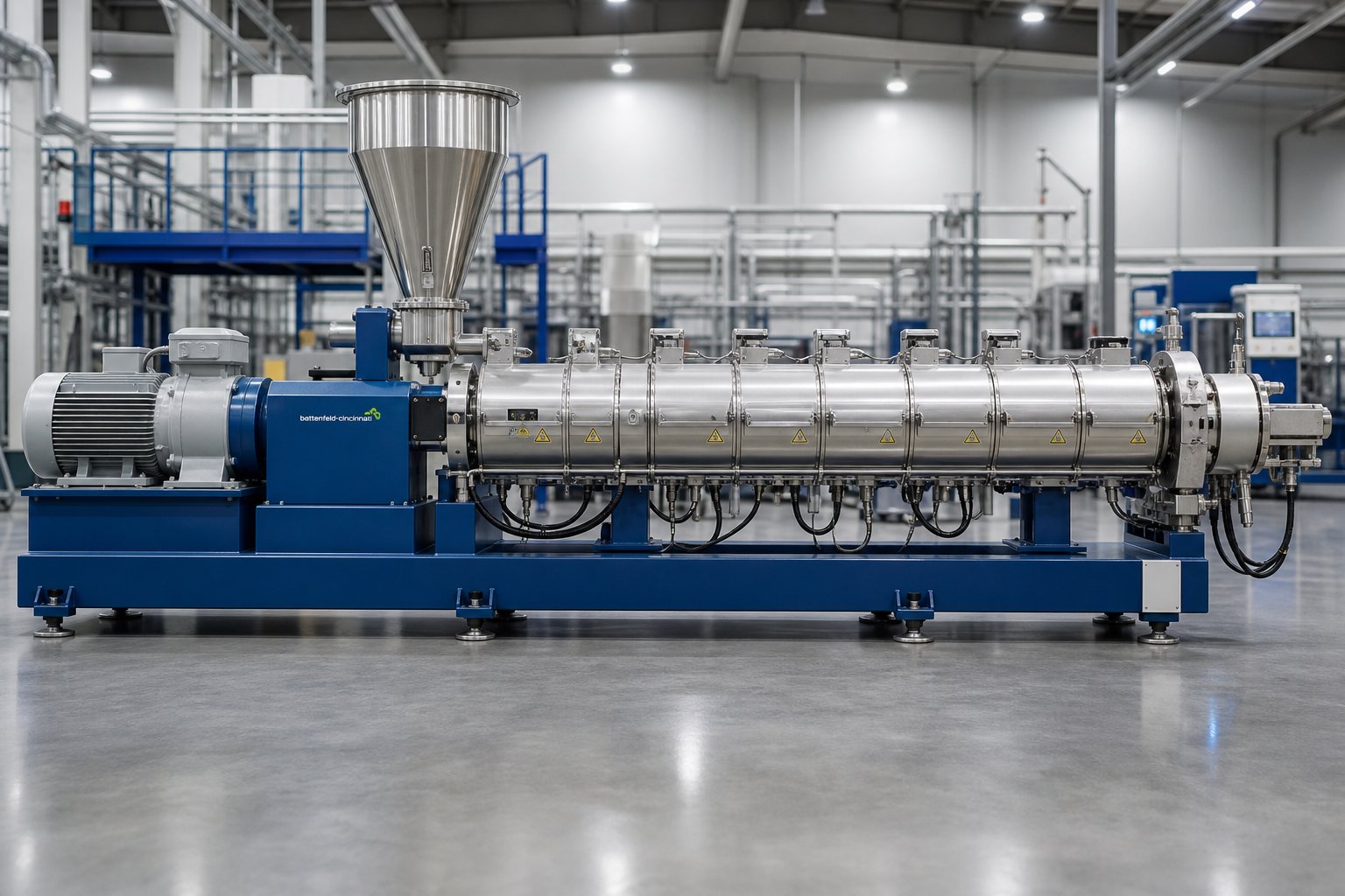
What Extrusion Machine Parts Are and Why They Matter
When an extrusion machine converts raw polymer pellets into continuous pipes, sheets, or profiles, it relies on dozens of precision-engineered components working in concert. Each one handles a specific job — melting, conveying, pressurizing, or shaping — and a single worn or mismatched part can tank your entire line's output quality.
What Are Extrusion Machine Parts
So, what is an extrusion machine at its core? It is a system of mechanical and thermal components designed to transform solid plastic material into a shaped, continuous product. The parts that make this happen include screws, barrels, heater bands, thermocouples, die heads, screen packs, gearboxes, and feed throats — each engineered to tight tolerances and specific metallurgical standards.
Extrusion machine parts are the individual mechanical and thermal components — including screws, barrels, dies, heater bands, and drive elements — that work together to melt, convey, meter, and shape raw polymers into finished extruded products with consistent cross-sectional profiles.
Think of these components as links in a chain. The screw generates shear heat and forward pressure. The barrel provides a controlled thermal environment. Heater bands and thermocouples regulate melt temperature zone by zone. The die gives the molten polymer its final shape. Remove or degrade any single link, and the entire process suffers — from dimensional inconsistency to energy waste.
Why Understanding Each Part Matters
Here is the reality many plant teams face: unplanned downtime often starts with a vague symptom — output drops, surface defects appear, or energy consumption creeps upward. Without a solid grasp of what each component does, troubleshooting becomes guesswork. You replace a heater band when the real culprit is a worn screw flight. You adjust barrel temperatures when a clogged screen pack is the actual bottleneck.
Deep component knowledge delivers three practical advantages:
- Faster root-cause diagnosis — You trace symptoms to specific zones and parts instead of adjusting everything at once.
- Accurate part sourcing — You communicate exact specifications to suppliers, reducing lead times and avoiding costly mis-orders.
- Smarter capital decisions — You evaluate whether a higher-grade barrel liner or a redesigned screw geometry will actually solve your throughput problem before spending.
Extrusion machines are not assembled from generic commodities. A screw designed for polyethylene will underperform — or even degrade material — if used to process PVC. A standard nitrided barrel wears rapidly when running glass-filled compounds. Every specification matters because every component directly influences melt quality, energy consumption, and final product consistency.
The sections ahead break down these components zone by zone, starting with where raw material first enters the system and following the polymer's path all the way through the die.
Extrusion Process Zones and Their Key Components
Every extrusion machine follows the same fundamental logic: take solid polymer in, push molten polymer out. But between those two endpoints, the material passes through distinct extrusion process zones — each with its own set of components, thermal conditions, and mechanical demands. Mapping parts to their zones is one of the fastest ways to sharpen your troubleshooting instincts and understand how the entire system behaves as a unit.
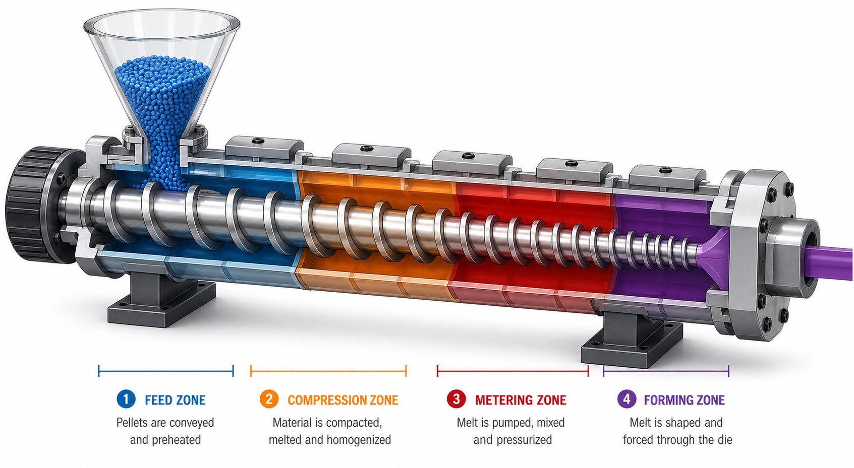
In a standard single-screw setup, the polymer travels through four primary zones: the feed zone, compression (or transition) zone, metering zone, and the forming zone at the die assembly. You will find different extrusion machine parts dominating each stage, and each set of components plays a non-negotiable role in delivering a consistent, high-quality melt to the die.
Feed Zone Components and Their Function
The feed zone is where everything begins. Raw pellets, granules, or powder drop from the hopper into the feed throat and land in the annular gap between the screw and the barrel wall. From here, the rotating screw flights grab the material and push it forward. Sounds simple? The engineering details say otherwise.
The feed hopper sits atop the extruder and relies on gravity to deliver material into the throat. Hopper design matters more than most operators realize. Materials with wide particle size distributions can bridge inside square hoppers, starving the screw. Circular cross-section hoppers handle uneven particle sizes better, and vibrating pads or stirrers are sometimes added to maintain steady flow. Low bulk-density materials pose a different challenge — trapped air can travel through the extruder and exit at the die, creating voids or surface defects in the extrudate.
Below the hopper, the feed throat connects the hopper to the barrel. This component comes in two distinct designs: smooth bore and grooved bore. Most single-screw extruders use smooth-bore feed throats, where solids transport depends heavily on friction between the polymer particles and the barrel wall. Feed efficiency with a smooth bore typically runs between 15% and 30% of the channel volume because particles slip against the throat surface.
Grooved-feed throats take a different approach. Machined grooves or interruptions in the throat wall resist particle rotation, compacting the polymer into a solid plug that the screw flights wedge forward. This design can multiply conveying efficiency and generate pressures exceeding 12,000 psi at the end of the grooved section. However, grooved designs require intensive water cooling to prevent premature melting, and they are sensitive to particle shape — regrind and soft polymers like many TPEs can plug the grooves.
Regardless of throat style, cooling the feed throat is essential. Without adequate water cooling, frictional heat and conducted barrel heat will soften pellets prematurely, causing them to stick to metal surfaces and restrict material flow. Effective cooling also maintains a thermal barrier between the cold feed entry and the heated barrel zones downstream.
Compression and Metering Zone Components
As the screw conveys material past the feed section, the polymer enters the compression zone — sometimes called the transition zone. Here, the screw's flight depth decreases progressively. Imagine squeezing a handful of pellets into an increasingly narrow channel: the material compacts, air is forced back toward the feed, and friction between particles and the barrel wall generates significant shear heat. This mechanical energy, combined with heat conducted from the barrel, is what drives the polymer from solid to melt.
In fact, the screw's mechanical action accounts for roughly 70% to 80% of the total melting energy in a typical machine extrusion process. The barrel heaters supplement this, but the screw does the heavy lifting.
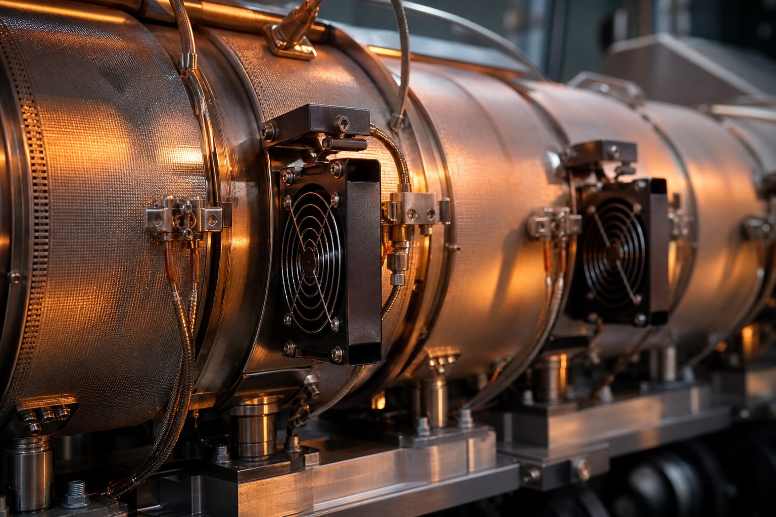
The barrel sections in the compression zone are wrapped with independently controlled heater bands, each monitored by thermocouples embedded in the barrel wall. The heater bands establish a gradually increasing temperature profile from feed to discharge, while the thermocouples feed real-time temperature data back to the control system. When shear heating in the compression zone pushes melt temperature above the setpoint, barrel cooling fans activate to bleed off excess heat — a balancing act that prevents thermal degradation.
Past the compression zone lies the metering zone, where the screw's flight depth is once again constant — but shallower than in the feed section. This zone's job is deceptively straightforward: deliver a homogeneous melt at consistent pressure to the die. The shallow channel depth maintains controlled shear, ensuring uniform melt temperature and viscosity. Any inconsistency here — from worn flights, improper screw design, or temperature fluctuation — shows up directly as dimensional variation in the finished product.
Forming Zone and Die Assembly
After the metering zone, the melt enters the forming zone — the final stage where raw polymer transforms into a shaped extrudate. Several critical components operate in sequence here.
The breaker plate sits at the barrel's discharge end. Its primary job is to stop the spiraling rotational motion imparted by the screw and redirect the melt into straight-line flow. Without it, that spiral memory can carry through to the die exit, causing distortion in the finished product. The breaker plate also serves as a structural support for the screen pack — a layered assembly of wire mesh screens that filters contaminants from the melt and adds back pressure to improve homogeneity.
Screen packs typically use a coarse-fine-coarse mesh layering, where the coarser outer screens provide structural support and the finer inner screens handle filtration. For processes with high contaminant loads, automatic screen changers allow used screens to be swapped out hydraulically without stopping the extruder — a critical feature for maintaining continuous production.
An adapter connects the barrel exit to the die head when the two geometries do not match directly. The die itself is where the melt acquires its final cross-sectional shape. Whether it is a flat die for sheet, an annular die for pipe, or a profile die for custom shapes, the die's internal flow channels must deliver uniform melt velocity across the entire exit opening. Stagnation points or uneven flow distribution will show up immediately as thickness variation or surface defects.
The table below maps each extrusion process zone to its primary components, functions, and general operating temperature ranges:
| Process Zone | Primary Components | Function | Typical Temperature Range |
|---|---|---|---|
| Feed Zone | Hopper, feed throat (smooth or grooved), initial screw flights | Receives and conveys solid polymer; controls material intake consistency | Cooled (feed throat) to 150-200 °F / 65-95 °C (barrel entry) |
| Compression / Transition Zone | Tapered screw flights, barrel sections, heater bands, thermocouples, cooling fans | Compresses, melts, and plasticizes the polymer through shear and conducted heat | 300-500 °F / 150-260 °C (varies by polymer) |
| Metering Zone | Constant-depth screw flights, heater bands, thermocouples, melt pressure transducers | Delivers homogeneous melt at uniform pressure and temperature to the die | 350-550 °F / 175-290 °C (varies by polymer) |
| Forming Zone | Breaker plate, screen pack, adapter, die head | Filters contaminants, eliminates melt rotation, shapes the extrudate | 350-550 °F / 175-290 °C (matched to metering zone) |
Why does this zone-based view matter for day-to-day operations? Because it turns vague symptoms into targeted diagnostics. A pressure spike registering after the metering zone — between the breaker plate and die — points toward screen pack blockage or a restrictive die, not a screw issue. Inconsistent feed with output surging and starving suggests hopper bridging, a feed throat cooling problem, or worn initial screw flights. Temperature overshoot in the compression zone likely means the barrel fans are undersized or the heater band setpoints need lowering to account for high shear heat contribution.
When you think in terms of extrusion systems rather than isolated parts, each symptom narrows your search to a specific zone and a short list of suspect components. That precision is what separates a four-hour troubleshooting marathon from a 30-minute fix.
Of course, the screw itself deserves far more attention than a zone overview can provide. Its geometry — flight depth, compression ratio, and mixing features — is the single biggest variable determining melt quality and throughput capacity, a subject that demands its own detailed examination.
Screw Types and Design Parameters That Drive Performance
If you could change only one component on your extrusion extruder to improve output quality, the screw would be that component. It dictates how polymer melts, how fast it moves, how uniformly it mixes, and how much energy the drive motor consumes doing it. Yet screws are not interchangeable commodities — a geometry optimized for LDPE film will produce poor results on rigid PVC pipe, and a general-purpose design may leave performance gains on the table for either application. Understanding extruder screw design parameters is what separates reactive part swapping from deliberate process optimization.
Single-Flighted, Barrier, and Mixing Screw Designs
The most common screw you will encounter in the field is the single-flighted (full-flight) screw. It features one continuous helical flight running from the feed end to the discharge. Material is conveyed, compressed, and melted as the channel depth gradually decreases. This design is economical, predictable, and easy to refurbish — making it the workhorse for straightforward melting and conveying tasks where intensive mixing is not the primary concern.
When melt quality demands more than a standard flight can deliver, the barrier screw steps in. A secondary flight — slightly undercut from the barrel wall — divides the main channel into two parallel paths: one carrying the solid bed, the other collecting the melt film as it forms. This separation forces solids against the hot barrel surface for faster melting while preventing unmelted particles from reaching the metering zone. The result? Improved temperature uniformity, reduced unmelts, and often higher throughput at the same screw speed.
For applications involving colorants, additives, or multi-component blends, mixing screws incorporate specialized elements along their length. These come in two flavors:
- Distributive mixing elements (such as pin sections or pineapple mixers) — repeatedly split and recombine melt streams to spread minor components evenly without generating excessive heat.
- Dispersive mixing elements (such as Maddock or fluted mixers) — force the melt through tight clearances at high shear stress to break down agglomerates like pigment clusters or undispersed filler particles.
When do you choose which? A single-flighted screw handles natural-color polyolefin pelletizing efficiently. A barrier design is preferred when you need higher output without sacrificing melt consistency — common in pipe and profile extrusion. Mixing elements become necessary when homogeneity of color or additive dispersion is a measurable quality requirement.
Critical Screw Parameters and Their Effects
Beyond the type of flight arrangement, three geometric parameters define how any screw behaves inside the barrel. Getting these right is the difference between an extrusion extruder that hums and one that fights you every shift.
- L/D Ratio (Length-to-Diameter) — This is the screw's effective length divided by its outer diameter. A typical single-screw extruder runs between 24:1 and 36:1. Higher L/D ratios provide more residence time inside the barrel, allowing gentler melting at lower screw speeds. If you increase screw RPM to boost throughput, a longer screw compensates by giving the polymer more time and distance to fully plasticize. Shorter L/D ratios suit easily melted resins where fast discharge prevents thermal degradation.
- Compression Ratio — Defined as the volume of one flight in the feed section divided by the volume of one flight in the metering section. General-purpose screws typically fall in the 2:1 to 3:1 range. Low bulk-density materials like crushed film may need ratios up to 4:1 or 5:1 to adequately compact and melt the feed. A compression ratio that is too high generates excessive shear heat, potentially degrading sensitive polymers. Too low, and unmelted pellets pass through to the die.
- Metering Zone Flight Depth — The shallower this channel, the higher the shear rate imposed on the melt. High shear improves mixing and heat generation but risks degradation in heat-sensitive resins. Deeper metering channels produce gentler shear and lower melt temperatures — beneficial for materials like PVC that have a narrow processing window. The flight depth in this zone also controls the balance between drag flow (forward) and pressure flow (backward), directly determining the screw's pumping efficiency.
These parameters do not operate in isolation. Increasing the compression ratio while keeping L/D short, for example, forces rapid compression over a short distance — creating intense shear spikes that can degrade polymer or cause surging. Every parameter must be balanced against the others and matched to the specific resin's bulk density, melt viscosity, and thermal sensitivity.
Screw Tips and Check Rings
In injection-style extrusion and some accumulator head applications, the screw tip and check ring assembly control how melt flows during the injection stroke. The screw tip sits at the front of the screw, streamlining melt flow into the shot chamber. Behind it, the check ring (or non-return valve) acts as a one-way gate — it slides open to let melt pass forward during screw recovery, then seats closed during injection to prevent backflow.
When check ring surfaces wear, they no longer seal completely. The result is shot-to-shot inconsistency: melt leaks backward past the ring during injection, reducing actual shot volume and causing short shots or weight variation. These are among the most commonly replaced extrusion tools on injection-equipped lines, and even minor wear becomes measurable in part weight data.
Equally critical is the screw-to-barrel clearance along the flight lands. On a new screw, this radial gap is engineered tight enough to minimize melt backflow over the flights while still allowing rotation without metal-to-metal contact. Over time, abrasive fillers, corrosive gases, or simple high-hour operation wears the flight lands down, widening this clearance. The consequences compound: more melt leaks backward over the flights, pumping efficiency drops, the drive motor works harder to maintain output, and melt temperature becomes less uniform because recirculating polymer accumulates extra thermal history.
Tighter clearances reduce backflow and improve energy efficiency — but they also accelerate wear rates, especially when processing filled compounds. This tradeoff means that screw and barrel metallurgy must be selected together, a topic that leads directly into how barrels are constructed and how temperature control systems manage the thermal environment surrounding the screw.
Barrel Construction and Temperature Control Systems
The barrel is easy to underestimate. It looks like a thick steel tube — static, simple, passive. In reality, it is an active thermal and mechanical participant in every kilogram of polymer your line produces. Its metallurgy determines how long it resists the abrasive and corrosive forces inside, while the extrusion barrel heater bands, thermocouples, and cooling systems wrapped around its exterior orchestrate the precise thermal profile that transforms solid pellets into a uniform melt. Treat the barrel and its temperature control hardware as a single integrated unit, and you will understand why polymer extrusion equipment performance lives or dies at this interface.
Barrel Metallurgy and Liner Options
Every barrel starts as a cylindrical steel housing, but what lines its inner bore separates a barrel that lasts years from one that wears out in months. The two primary approaches are nitriding and bimetallic lining — and the choice maps directly to what you are processing.
Nitrided barrels use a gas diffusion process to harden the bore surface of the base steel. Nitrogen atoms penetrate approximately 0.4 to 0.7 mm deep, forming a hard nitride case that resists moderate sliding wear. For clean, non-abrasive resins — think natural PP, PE, PS, or ABS with no fillers — a nitrided barrel in a steel like 38CrMoAlA delivers reliable service at a lower cost than bimetallic options. The hardened case handles these duties without issue, and paying for a premium liner would be overengineering.
Where nitriding falls short is anywhere abrasion or corrosion enters the picture. That thin case erodes quickly once glass fiber, talc, calcium carbonate, or mineral fillers start acting like sandpaper against the bore wall. Once the case wears through, softer core steel is exposed and erosion accelerates dramatically.
Bimetallic barrels solve this by adding a separate wear-resistant alloy layer — typically 2.0 to 3.0 mm thick — centrifugally cast inside the barrel bore. The alloy chemistry is selected based on duty:
- Iron-boron alloys (Fe+Ni+Cr+B compositions) — general-purpose wear grades offering high hardness (HRC 58-62) for abrasive fillers at temperatures up to approximately 400 degrees C.
- Nickel-based alloys (Ni+Cr+Co+B or Ni+Cr+Co+V+B compositions) — shift the balance toward corrosion resistance, making them the mandatory choice for PVC processing where hydrochloric acid release at processing temperatures attacks unprotected steel.
- Tungsten carbide-bearing alloys (Ni+Wc+Cr+B compositions) — the premium tier for the most aggressively abrasive compounds, tolerating temperatures up to approximately 600 degrees C with the highest anti-wear rating available.
Why does PVC specifically demand corrosion-resistant barrel metallurgy? Because PVC begins releasing HCl gas at its processing temperature. Even small amounts of thermal degradation — from a stagnation point in the flow path or a hot spot in the barrel — liberate this corrosive byproduct. A standard nitrided barrel pit-corrodes under these conditions, while a nickel-based bimetallic liner resists chemical attack and extends barrel life significantly.
For glass-filled nylon or heavily mineral-loaded compounds, imagine thousands of tiny abrasive particles scouring the bore wall with every screw rotation. A nitrided surface that might last several years on clean resin can wear through its case in a fraction of that time under abrasive loading. Tungsten carbide-bearing liners earn their higher cost through dramatically extended service intervals on these demanding applications.
Heater Band Types and Zone Configuration
Wrapped around the barrel's exterior, heater bands supply the conducted heat that supplements the screw's mechanical shear energy. But not all extruding equipment heaters are created equal. Three main types serve different operational priorities, and selecting the right one for each barrel zone directly affects energy consumption, temperature stability, and maintenance frequency.
Mica band heaters are the most economical option. They use NiCr resistance ribbon wound around a phlogopite mica core, sandwiched inside a thin stainless steel sheath. Heat transfer relies almost exclusively on conduction — the heater must maintain tight, uniform contact with the barrel surface. Their ultra-thin profile (typically 3-5 mm) makes them ideal for space-constrained installations, and they offer extremely fast thermal response due to low thermal mass. However, mica heaters are limited to a maximum operating temperature of 340 degrees C and a maximum watt density of 3 W/cm squared. Above these thresholds, the organic binders in the mica sheets carbonize and become conductive, causing dielectric failure.
Ceramic band heaters operate on a dual-transfer principle — both conduction and far-infrared radiation. Internal resistance coils are threaded through interlocking steatite ceramic knuckles, which absorb heat and radiate it toward the barrel. A built-in 12 mm ceramic fiber insulation blanket positioned between the heating elements and the outer sheath forces thermal energy inward rather than radiating it into the plant environment. This design safely handles temperatures up to 600 degrees C and watt densities up to 6 W/cm squared. Real-world audits show that ceramic heaters reduce power consumption by 25% to 30% compared to uninsulated mica bands on the same barrel zone, because the PID controller cycles less frequently to maintain setpoint.
Cast aluminum heaters take a different engineering approach. Resistance elements are cast directly into an aluminum body that is precision-machined to match the barrel's outer diameter. The aluminum acts as a thermal reservoir, distributing heat uniformly across the entire contact surface and eliminating the localized hot spots that plague poorly clamped mica bands. Cast aluminum heaters offer excellent longevity and thermal uniformity — making them particularly valuable on metering zones where even minor temperature variations translate directly into melt viscosity inconsistency and dimensional defects in the finished product.
Each barrel zone — from feed to die — serves a different thermal purpose in the melt progression. The zone nearest the feed throat runs at the lowest setpoint (or may not be heated at all), preventing premature pellet softening. Compression zone heaters supplement shear-generated heat at moderate setpoints. Metering and adapter zones hold the highest and most tightly controlled temperatures, ensuring the melt arrives at the die with consistent viscosity. Selecting heater types zone by zone — rather than using one type across the entire barrel — optimizes both performance and operating cost.
| Heater Type | Max Temperature | Max Watt Density | Energy Efficiency | Typical Applications | Relative Longevity |
|---|---|---|---|---|---|
| Mica Band | 340°C (644°F) | 3 W/cm² | Low (no insulation; high ambient heat loss) | General processing of PE, PP, ABS; space-constrained zones; intermittent operation | Moderate — sensitive to loose clamping and contamination |
| Ceramic Band | 600°C (1112°F) | 6 W/cm² | High (built-in insulation reduces energy use 25-30%) | Engineering resins (PEEK, nylon); continuous 24/7 production; high-temperature zones | Long — tolerant of minor air gaps; resistant to thermal cycling |
| Cast Aluminum | 400-450°C (~750-840°F) | Moderate (varies by design) | Moderate-High (uniform distribution reduces cycling) | Metering zones requiring tight temperature uniformity; profile and sheet extrusion | Long — robust construction resists mechanical damage and thermal fatigue |
Thermocouples and Cooling Systems
Heater bands supply heat, but without accurate measurement and feedback, that heat is uncontrolled energy. Thermocouples are the sensory backbone of every barrel temperature control loop — and their placement, type, and condition directly determine how accurately your controller responds to real melt conditions.
Thermocouples measure temperature by generating a voltage proportional to the temperature difference between two dissimilar metal junctions. In extrusion, the most common calibrations are Type J and Type K, chosen based on the required temperature range and chemical environment. The critical engineering decision is placement depth: a thermocouple seated in a shallow well near the barrel's outer surface reads heater band temperature more than melt temperature. A deeper well — extending closer to the bore — provides a reading more representative of actual polymer conditions but responds more slowly to changes due to the thermal mass between the sensor tip and the bore wall.
This tradeoff matters in practice. A fast-responding shallow thermocouple gives the PID controller quick feedback, reducing overshoot when the heater cycles on. But it can be fooled — barrel surface temperature may look stable while the melt inside runs hotter or cooler than expected. Deeper placements provide truer melt-side readings but introduce lag that can cause the controller to overshoot before it registers the temperature change. Most experienced operators find the best compromise through trial and zone-specific tuning of PID parameters.
Equally important — and often overlooked — are the barrel cooling systems. Why would you need to cool a barrel that you are actively heating? Because in the compression zone, the screw's mechanical action generates substantial shear heat that can push melt temperature well above setpoint. If heater bands alone controlled temperature, the system could only add energy, never remove it. Air cooling fans (or in some designs, water cooling channels) mounted along the barrel provide the controller with a way to actively pull heat out of specific zones.
Without effective cooling, the compression zone becomes thermally uncontrollable — shear heat accumulates, melt temperature rises above the degradation threshold, and the resulting product shows discoloration, reduced mechanical properties, or surface defects. The interplay between heater bands adding energy, the screw generating shear energy, and cooling fans removing excess energy is what produces a stable, repeatable thermal profile across the barrel's length.
This interdependent relationship between barrel, screw, heaters, and cooling hints at a broader truth about extrusion machine parts: no component operates in isolation. The barrel's thermal behavior depends on what the screw is doing inside it. The heater bands respond to heat generated by screw geometry. The cooling system compensates for both. Change one variable, and the others must adjust — a principle that extends beyond the barrel to every component in the extrusion line.
Die Heads, Screen Packs, and Forming Components
Once homogeneous melt exits the metering zone, it still has three critical jobs left to complete before becoming a finished product: filtration, flow distribution, and final shaping. The components handling these tasks — screen packs, adapters, and die heads — determine whether all that upstream precision translates into quality extruded parts or gets lost to contamination, dimensional variation, and surface defects. Think of them as the last line of defense between your process and your customer's quality standards.
Screen Packs and Filter Adapters
The screen pack assembly performs triple duty in an extrusion line, and understanding all three functions helps you configure it correctly rather than treating it as a simple strainer.
First, contaminant filtration. Woven wire mesh physically blocks particles — carbonized fragments, gels, unmelted agglomerates, foreign debris — from reaching the die. Even high-quality virgin resin carries some level of inherent contamination from polymerization or handling. When recycled or regrind content enters the mix, this particle load increases dramatically. A screen pack positioned ahead of the die catches these contaminants before they can score flow channels, build up on die lips, or embed themselves as visible defects in the finished product.
Second, back pressure contribution. The screen pack creates flow resistance that increases melt pressure upstream of the breaker plate. This added back pressure helps the screw's metering section deliver more uniform shear and mixing. A clean screen adds modest resistance — but as contamination accumulates, pressure climbs progressively, increasing screw motor load and potentially reducing output if left unchecked.
Third, rotational memory elimination. Polymer exiting the screw carries a spiraling flow pattern from the helical flights. The breaker plate's perforated holes, combined with the screen pack's mesh structure, break up this rotational memory and redirect melt flow into a more linear pattern before it enters the die. Without this conversion, spiral flow can manifest as distortion or uneven wall thickness in extrusion products.
Screen mesh configurations follow a deliberate layering logic. A typical arrangement uses coarse-fine-coarse stacking: the coarser outer screens (lower mesh count) provide structural support against melt pressure, while the finer inner screens handle the actual filtration. For applications demanding tighter contamination control, multi-layer stacks add intermediate mesh sizes between the support and filtration layers.
Filter adapters house the screen pack and breaker plate in the melt stream and provide the mechanism for screen replacement. The simplest design is a bolt-on plate that requires stopping the line to swap screens. For operations where frequent changes are necessary — particularly lines processing recycled feedstock — screen changers offer a solution. Manual slide-plate changers allow quicker swaps with reduced downtime, while continuous screen changers use dual-station or hydraulically driven designs that replace one screen section while the other remains active in the melt stream. This keeps pressure fluctuation during changeover within a range most products can tolerate, minimizing scrap from pressure drop events.
Die Head Design and Function
The die is where everything your extrusion line has done — melting, mixing, pressurizing, filtering — either becomes a dimensionally accurate product or reveals upstream inconsistencies. Die design must accomplish one deceptively difficult task: distribute molten polymer uniformly across the entire exit opening so that every point along the cross-section receives equal melt velocity and pressure.
Flat dies produce sheet, film, and coating products. The melt enters through a central or end-fed inlet and must spread laterally to fill the full die width — which can span over a meter on wide sheet lines. Two primary flow distribution approaches handle this challenge:
- Coat-hanger manifold — A tapered internal channel shaped like a coat hanger gradually distributes melt from the center outward. The channel geometry is calculated so that every flow path from inlet to exit has equal resistance, producing uniform velocity across the full width. This is the dominant design for precision sheet and film applications.
- T-slot manifold — A simpler, less expensive design where melt flows into a cross-channel and exits through a slot. Flow uniformity depends more heavily on the restrictor bar or choker bar adjustment. Adequate for narrower dies and less demanding tolerances.
Annular dies produce hollow profiles — pipes, tubes, and blown film. Melt enters from one side and must wrap around a central mandrel to form a complete ring at the exit. Spider legs or spiral mandrel channels distribute the melt circumferentially. Spider-leg designs are simpler but leave weld lines where flow streams rejoin. Spiral mandrel dies overlap multiple flow channels to eliminate visible weld lines — critical for pressure-rated pipe and optical-quality blown film.
Profile dies produce complex custom cross-sections — window frames, gaskets, trim, medical tubing with multiple lumens. These are the most challenging to design because irregular shapes create unequal flow paths. Thicker sections fill faster than thin sections, requiring careful balancing of channel lengths and restrictions within the die body.
Two die geometry parameters have outsized influence on your finished product:
- Die land length — The parallel section at the die exit where the melt stabilizes before emerging. Longer land lengths produce smoother surfaces and more dimensionally stable extrudates because they allow the melt's velocity profile to fully develop. Shorter lands reduce pressure drop but sacrifice surface quality. As extrusion specialist Allan Griff notes, thickness management also depends on swell, shrinkage, and drawdown — all of which interact with how the melt exits the die land.
- Lip gap — The opening dimension at the die exit. This determines initial extrudate thickness before drawdown. Adjustable lip gaps (via manual bolts or automatic systems) allow operators to fine-tune thickness distribution. Running faster pushes more material through the same gap, and different resins swell differently after exiting, so the lip gap setting is always material- and rate-specific.
Streamlined internal flow passages — with no sharp corners, dead spots, or abrupt geometry changes — are essential regardless of die type. Stagnation points allow polymer to sit, degrade, and eventually release as discolored specks or carbonized fragments into the product stream. This is especially critical for PVC and other thermally sensitive resins with narrow processing windows.
Pelletizing Blades and Downstream Forming
Not every extrusion line produces a continuous profile. Compounding operations convert melt into pellets — the feedstock for injection molding, blow molding, and further extrusion. Two primary pelletizing methods dominate, and blade geometry plays a central role in pellet quality for both.
Strand pelletizing extrudes multiple melt strands through a multi-hole die plate, cools them in a water bath, then feeds the solidified strands into a rotary cutter. Blade sharpness and the gap between the cutting edge and the bedknife determine whether strands shear cleanly or produce tails, dust, and irregular shapes. Dull blades crush rather than cut, creating fines that clog downstream handling equipment.
Underwater pelletizing cuts the melt directly at the die face. Blades rotate against a heated die plate while process water flows across the cutting zone, instantly quenching pellets into solid form. Blade tip speed is a critical variable — too fast and low-viscosity materials smear rather than shear cleanly, producing tails that break off during drying and generate fines. Too slow and pellets do not separate cleanly from the die face, forming doubles or chains. Optimal speed depends on resin viscosity, die hole diameter, and the number of blades on the cutter hub.
Die and blade wear compound each other. As die holes erode from abrasive fillers, their exit geometry changes — altering how cleanly the blade can shear the melt strand. Worn blades that no longer seat flush against the die plate allow melt to smear between the cutting edge and the plate surface, creating the tails and agglomerates that degrade pellet consistency.
Beyond the die and pelletizer, downstream extrusion equipment completes the product-forming process. These components vary by application but share a common purpose — taking the raw extrudate from the die and converting it into a finished, dimensioned, packaged product:
- Calibration tanks (vacuum or pressure) — Size and cool the extrudate immediately after the die, locking in the final cross-sectional dimensions while the polymer is still pliable.
- Cooling tanks or spray systems — Remove residual heat from the extrudate to solidify the polymer fully before mechanical handling.
- Haul-off / pullers — Apply controlled tension to draw the extrudate at a constant speed, determining final wall thickness through drawdown ratio.
- Rotary cutters or flying saws — Cut the continuous extrudate into specified lengths without stopping the line.
- Coilers or winders — Spool flexible products (tubing, cable, film) into manageable rolls for shipping and storage.
- Thickness / diameter gauges — Provide real-time dimensional feedback for closed-loop control of line speed and die adjustment.
Here is the principle that ties all forming components back to the rest of the machine: die design must match upstream melt delivery. An undersized die — one whose flow channels are too restrictive for the extruder's output capacity — creates excessive back pressure that propagates backward through the entire system. The gearbox thrust bearing absorbs higher axial loads. The screw works against greater resistance, increasing motor current and melt temperature. Screen pack loading accelerates because higher pressure forces more contaminant into the mesh. One mismatched component at the end of the line stresses every component before it.
This interconnectedness — where a single part change ripples through the entire process — is not unique to the die. It is a fundamental characteristic of how extrusion machine parts behave as a system, and understanding those ripple effects is what separates reactive maintenance from proactive process management.
How Extrusion Machine Parts Work Together as a System
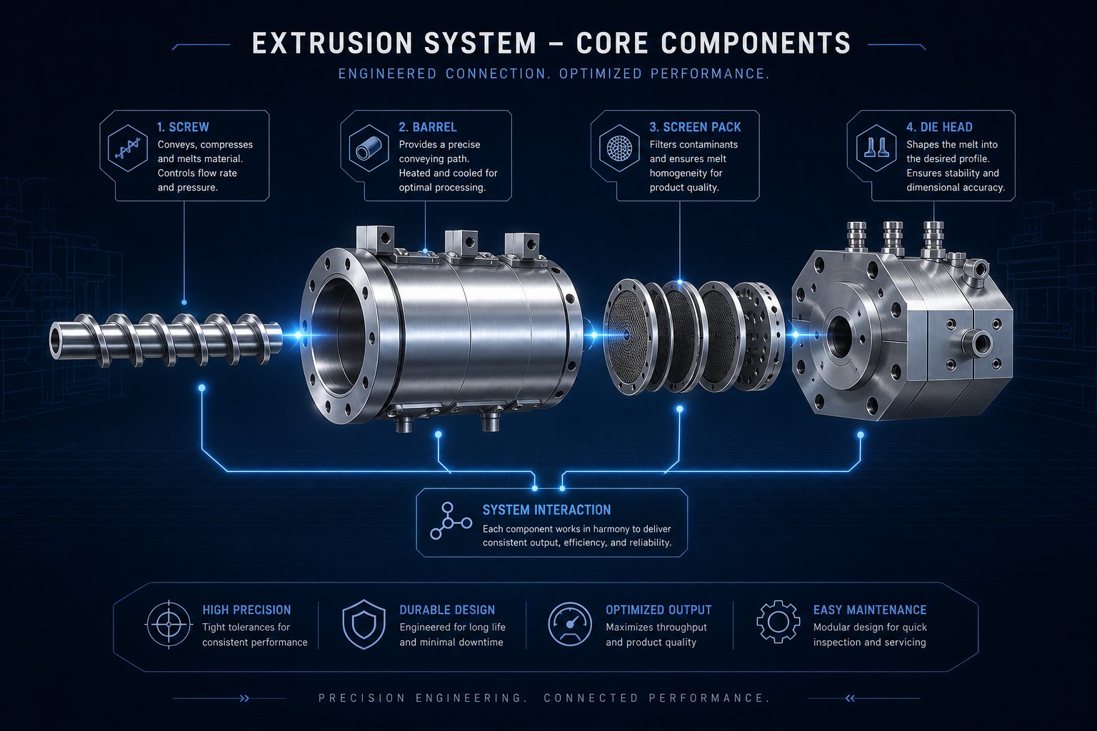
Imagine swapping the engine in your car without checking whether the transmission, exhaust, and cooling system can handle the new power output. That is essentially what happens when a maintenance team changes one extrusion component without considering how it interacts with everything else on the line. Extrusion machinery does not operate as a collection of independent parts — it behaves as a tightly coupled system where pressure, temperature, torque, and flow rate constantly feed back on one another. Understanding this extrusion machine components interaction is what prevents a well-intentioned upgrade from becoming a new set of problems.
Every part change is a system change. Adjusting one component's geometry, clearance, or restriction alters the pressure, temperature, and load conditions experienced by every other component in the melt path.
How Screw Changes Affect the Entire System
You install a higher-compression screw to improve melt homogeneity. The immediate effect is straightforward — deeper compression generates more shear heat and higher melt pressure at the screw tip. But here is where the ripple effects begin:
- Heater band setpoints may need to come down. The additional shear heat means the barrel's electrical heaters contribute a smaller fraction of total melting energy. If setpoints stay unchanged, actual melt temperature overshoots, risking degradation — particularly on thermally sensitive resins.
- Screen pack pressure increases. Higher discharge pressure from the screw pushes more forcefully against the screen pack and breaker plate. A screen configuration that ran comfortably at 2,500 PSI may now see 3,200 PSI or more, accelerating screen loading and shortening change intervals.
- Die pressure ratings must accommodate the change. If your die was operating near its rated pressure with the old screw, the new geometry may push it past safe limits — causing deflection, leaks at parting lines, or accelerated lip wear.
- Motor current rises. A higher-compression screw demands more torque to rotate against increased melt resistance. If the drive motor was already running above 80% of rated load, the new screw may push it into overload conditions during startup with cold material, where peak torque can exceed steady-state running torque by 20-40%.
None of these consequences are visible at the moment you bolt the new screw in. They emerge gradually — as higher reject rates, faster screen loading, or a gearbox that starts running hotter than it used to.
Barrel Wear and Its Cascading Effects
Barrel wear is slower and subtler than a screw swap, but its system-wide consequences are just as significant. As the barrel bore enlarges from abrasive filler contact or corrosive attack, the clearance between the screw flight lands and the barrel wall widens. This growing gap sets off a chain reaction that touches virtually every performance metric on the line.
First, pumping efficiency drops. Molten polymer that should travel forward over the flights instead leaks backward through the widened clearance. Output at a given screw speed declines — and operators often compensate by increasing RPM, which accelerates wear further. Data from predictive maintenance programs shows that output falling below 85% of rated capacity at a given RPM indicates wear has progressed to the point where replacement planning should begin.
Second, energy consumption climbs. The motor works harder to maintain throughput because a larger fraction of the screw's pumping energy is lost to recirculation rather than forward conveyance. Specific energy — measured in kWh per kilogram of output — trends upward as wear progresses.
Third, melt temperature uniformity degrades. Polymer that recirculates over worn flights accumulates additional shear history. Some melt passes through the metering zone once; some passes through twice or more. The result is a melt stream with inconsistent thermal history — hotter in some portions, cooler in others — producing dimensional variation and mechanical property inconsistency in the finished product.
The insidious aspect of barrel wear is that it happens gradually enough that operators adapt to the declining performance without recognizing the root cause. Output is lower, so they raise screw speed. Melt temperature runs high, so they drop heater setpoints. These compensations mask the real issue until wear reaches a critical threshold where no amount of adjustment restores acceptable output.
Gearbox Load and Drive System Interactions
The gearbox sits between the motor and screw, performing what seems like a straightforward mechanical function — reducing speed and multiplying torque. But it also absorbs the axial thrust load created when the screw pushes polymer forward against the die's resistance. This thrust load is not static. It responds to every downstream restriction in the extruding machinery flow path.
Consider what happens when a screen pack loads with contamination. Pressure upstream of the screen rises. That increased pressure pushes backward against the screw, increasing the axial thrust load on the gearbox's thrust bearing. Similarly, a restrictive die — whether by design or from buildup on the die lips — generates higher back pressure that the gearbox must absorb. In twin-screw configurations, these back pressure forces can range from 2.5 kN on small machines to 3,400 kN on large production units.
Thrust bearing fatigue is cumulative. Every hour running at elevated back pressure chips away at the bearing's rated life. The theoretical calculation life of extruder thrust bearings targets approximately 12,000 hours under normal operating conditions — but "normal" assumes the downstream flow path maintains its designed restriction level. A chronically loaded screen pack or a die running above its intended pressure rating can halve that bearing life without any visible symptom until the bearing fails catastrophically.
The practical takeaway? A blocked screen pack is not just a filtration problem — it is a gearbox life problem. A worn barrel is not just a pumping efficiency problem — it is a melt quality, energy consumption, and motor load problem. Every component in the melt path shares a load budget, and exceeding that budget in one area steals life from components elsewhere.
This systems perspective changes how smart maintenance teams approach their work. Rather than replacing parts in isolation, they evaluate the system state: Is the new screw compatible with the current barrel clearance? Will the die handle the pressure from a finer screen pack? Can the gearbox sustain the thrust load if throughput increases? Asking these questions before making changes — rather than diagnosing consequences afterward — is what transforms reactive maintenance into proactive process management. And it starts with knowing which material-specific part configurations your particular polymer demands.
Material Compatibility and Part Configuration Guidance
Here is a scenario that plays out in plants every week: a line that ran beautifully on HDPE pipe gets reassigned to process glass-filled nylon — and within months, the screw flights are visibly worn, barrel bore measurements show alarming growth, and pellet quality deteriorates. The operator did nothing wrong. The plastic extrusion parts simply were not engineered for the new material's demands.
Different polymer families impose fundamentally different mechanical, thermal, and chemical stresses on every component in the melt path. A screw geometry that delivers perfect melt homogeneity for polypropylene will scorch PVC. A barrel liner that handles clean ABS for years will erode in weeks under calcium carbonate-filled compounds. Matching your polymer processing equipment parts to the specific material you run is not optional refinement — it is the baseline requirement for sustainable production.
Polyolefins and Styrenics Part Configurations
Polyethylene (PE) and polypropylene (PP) are semi-crystalline polymers with relatively high crystallinity. What does that mean for component selection? These materials undergo a distinct solid-to-melt phase change that requires significant energy input to break down the crystalline structure. They tolerate — and in fact need — substantial shear heating to melt completely.
Screw design for polyolefins reflects this tolerance. Compression ratios in the 3.0 to 4.0 range are typical because these resins can absorb the shear energy without degrading. The channel depth decreases aggressively from feed to metering, generating enough compaction and frictional heat to fully plasticize the crystalline structure. L/D ratios between 24:1 and 30:1 provide adequate residence time for complete melting at standard production speeds.
Barrel requirements are straightforward for unfilled polyolefins. A standard nitrided barrel handles clean PE and PP without issue — these resins are neither abrasive nor corrosive under normal processing temperatures. Die design is similarly conventional, though polyolefins exhibit relatively high die swell (the extrudate expands after exiting the die), which must be accounted for in lip gap settings and downstream calibration tooling.
Styrenics — polystyrene (PS) and ABS — behave differently. These are amorphous polymers with no crystalline structure to break down. They soften gradually rather than melting sharply, requiring less shear energy to reach a processable state. Compression ratios of 2.5 to 3.0 suit most styrenic applications, delivering enough compaction without overheating the melt. Because styrenics have lower melt viscosity than polyolefins at equivalent temperatures, mixing sections become more important for color dispersion and additive homogeneity. A distributive mixing element near the screw tip ensures uniform blending without the excessive shear that can degrade ABS's rubber phase.
PVC and Corrosive Polymer Considerations
If polyolefins are the forgiving workhorses of industrial extrusion machinery, PVC is the demanding specialist that punishes any compromise in component selection. Processing rigid PVC correctly requires attention to corrosion resistance, thermal precision, and flow path geometry in ways that no other commodity resin demands.
The core challenge? PVC releases hydrochloric acid (HCl) during processing. Even under ideal conditions, some thermal decomposition occurs at melt temperature — and that decomposition produces a corrosive gas that attacks unprotected metal surfaces. Screws and barrels must be made from corrosion-resistant materials, such as nickel-based bimetallic alloys or chrome-plated surfaces, to withstand this chemical attack over thousands of production hours.
Beyond corrosion, PVC has an extremely narrow processing window. Too hot, and the material degrades rapidly — releasing more HCl, discoloring, and losing mechanical properties. Too cold, and it does not fuse properly, producing a weak, porous extrudate. This window can be as narrow as 10-15 degrees C between under-processing and degradation, which is why thermocouple accuracy and placement depth become critical rather than merely important. A drifted thermocouple reading just 5 degrees off can push you outside the safe zone without any visible indication until defects appear in the product.
Screw geometry for rigid PVC demands low compression ratios — typically 1.5:1 to 2.5:1 — to minimize shear heat generation. Higher ratios that work perfectly for polyolefins would scorch PVC within the first few minutes of production. Specialized screw profiles with barrier flights or optimized mixing zones ensure uniform melting without the localized hot spots that trigger degradation.
Die design for PVC carries its own unique requirement: streamlined flow passages with zero stagnation points. Any dead zone — a sharp corner, an undercut, or a poorly transitioned geometry change — allows material to sit, overheat, and degrade. That degraded material eventually breaks free as black specks or carbonized fragments in the product stream. Every internal surface must maintain continuous flow with no areas where polymer can hang up and accumulate thermal history.
Engineering Resins and Filled Compounds
Glass-filled nylon, mineral-loaded polycarbonate, and other engineering-grade compounds represent the opposite end of the wear spectrum from clean polyolefins. These materials are essentially abrasive slurries — thousands of hard particles suspended in a viscous carrier, scouring every metal surface they contact with each revolution of the screw.
Component selection for these materials prioritizes wear resistance above all else. Flight lands — the outermost edge of the screw flight that rides closest to the barrel wall — see the most intense abrasion because they experience the highest relative velocity and the most concentrated particle contact. Hardened flight lands using stellite or tungsten carbide overlays resist this abrasion far longer than standard nitrided surfaces. For the barrel, tungsten carbide-bearing bimetallic liners provide the highest abrasion resistance available, dramatically extending service intervals compared to iron-boron alloys or nitrided steel.
Screw design for filled compounds must balance two competing requirements. The material needs enough shear energy to melt the polymer matrix completely — but excessive shear breaks reinforcing fibers, destroying the mechanical properties that justify using an engineering resin in the first place. Compression ratios trend lower (toward 2:1) because the filler particles themselves contribute shear energy during processing, and the goal is to protect fiber length rather than maximize melting intensity. Gentle transition zones with gradual depth changes avoid the sudden compaction that snaps glass fibers.
L/D ratios for filled compounds often run higher (30:1 to 36:1) to provide the residence time needed for complete melting at lower shear rates. This allows the polymer matrix to plasticize fully without subjecting the reinforcement to unnecessary mechanical damage.
The table below maps common polymer families to their recommended component configurations. These are general starting guidelines — specific grades, filler loadings, and end-product requirements will shift the ideal specifications for your application:
| Polymer Family | Recommended Screw Geometry | Barrel Lining | Die Design Considerations |
|---|---|---|---|
| PE / PP (unfilled) | Compression ratio 3.0-4.0; L/D 24:1-30:1; standard or barrier flights; mixing section for color applications | Standard nitrided (38CrMoAlA or equivalent) | Account for high die swell; coat-hanger manifold for sheet; spiral mandrel for pipe |
| PS / ABS (unfilled) | Compression ratio 2.5-3.0; L/D 24:1-28:1; distributive mixing element for color homogeneity | Standard nitrided | Moderate die swell; lower melt viscosity allows simpler flow distribution; avoid sharp corners that trap ABS rubber phase |
| Rigid PVC | Compression ratio 1.5-2.5; low-shear profile; barrier or optimized mixing zones; possible degassing section | Nickel-based bimetallic (corrosion-resistant); chrome-plated screw surfaces | Fully streamlined passages; no stagnation points; no sharp geometry transitions; tight temperature control at die |
| Glass-filled Nylon / PA | Compression ratio ~2.0-2.5; gradual transitions to preserve fiber length; hardened flight lands (stellite/WC overlay); L/D 30:1-36:1 | Tungsten carbide-bearing bimetallic liner | Hardened die lips to resist erosion; streamlined flow paths to minimize fiber orientation issues; wider land lengths for surface quality |
| Mineral-filled Engineering Resins (PC, PBT, POM) | Compression ratio 2.0-3.0; moderate shear; dispersive mixing for filler distribution; hardened flights | Iron-boron or tungsten carbide bimetallic (depending on filler loading and abrasiveness) | Polished flow surfaces; balanced manifold design; temperature uniformity critical for crystalline grades |
Notice the pattern: as you move from forgiving polyolefins toward demanding engineering compounds, every component specification shifts — harder metallurgy, gentler screw geometry, more precise thermal control, and more carefully engineered flow paths. The material you process dictates the parts you need. A line configured for one polymer family and then reassigned to another without changing the wear components and screw geometry is not being repurposed — it is being sacrificed.
This material-specific logic feeds directly into maintenance planning. If you know that glass-filled compounds accelerate screw flight wear by a factor of three to five compared to unfilled resin, you can predict when tolerances will drift outside acceptable limits and schedule replacement before quality deteriorates. That kind of proactive approach — measuring, tracking, and anticipating wear — is what separates plants that manage component life from those that react to failures after the damage is done.
Maintenance, Tolerances, and Failure Mode Recognition
Predicting when a component will fail is far more profitable than reacting after it does. The previous section showed how material selection drives wear rates — glass-filled compounds erode flight lands several times faster than clean polyolefins, and PVC chemically attacks unprotected barrel surfaces. But knowing that wear happens is only half the equation. The other half is knowing how to measure it, what failure patterns to watch for, and when to act. That is where structured extrusion machine maintenance parts inspection programs separate high-uptime plants from ones perpetually fighting unplanned shutdowns.
Critical Tolerances and What to Inspect
If you could track only one measurement on your extruding machines, it should be screw-to-barrel clearance. This single dimension reveals more about your extruder's health than any other reading — because as clearance grows, pumping efficiency drops, energy consumption rises, melt temperature uniformity degrades, and product quality deteriorates in a self-reinforcing cycle.
How tight is that clearance on a healthy machine? As a widely used industry guideline, the radial flight clearance on a new screw is approximately the nominal screw diameter divided by 1,000. For a 3.5-inch extruder, that means roughly 0.004 inches per side — the screw's outer flight diameter is about 3.492 inches, with the barrel bore at the nominal 3.500 inches plus a tolerance of 0.001 inches oversize. That gap is tight enough to minimize melt backflow over the flights yet loose enough to allow rotation without metal-to-metal contact.
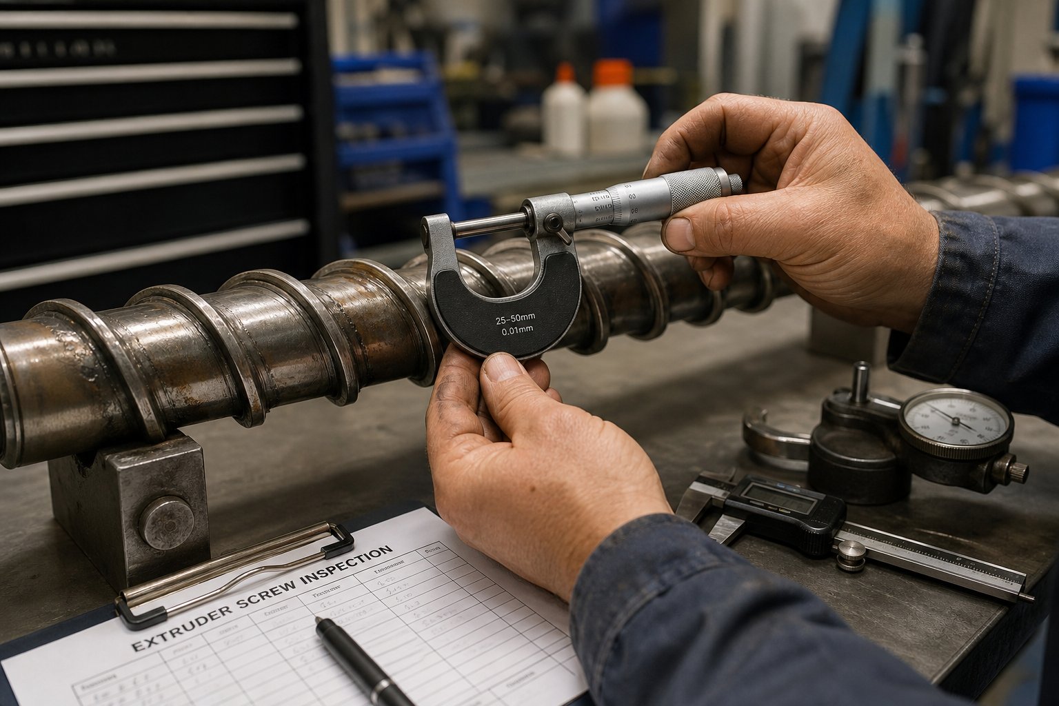
Measuring the barrel bore requires a dial bore gauge (sometimes called a telescoping gauge paired with a micrometer for smaller diameters). The process involves cleaning the barrel thoroughly — purging residual polymer, then scrubbing the bore with brass gauze while it cools to room temperature. Measurements should be taken every two to three inches down the barrel's length, not just at a few random points. Frequent measurements reveal localized wear patterns that spot checks miss entirely. You will typically find the most significant bore enlargement near the middle of the barrel, where polymer melting generates the highest combination of pressure and abrasive particle contact.
For the screw, flight outer diameter is measured with an outside micrometer at every other flight. Root diameter — the channel floor between flights — should be measured between every other flight and at each axis through the feed and metering sections. The flight tips, the shank threads, and the nose assembly all get visual inspection for washouts, scoring, or deformation.
What constitutes acceptable wear versus a replacement trigger? The answer depends on your extruder diameter, the criticality of your application, and your tolerance for output loss. Some common guidelines from industry practice include:
- New condition — Flight clearance at the diameter/1000 baseline. Optimal pumping efficiency and discharge temperature control.
- Moderate wear — Clearance at roughly 2x the original specification. Output may be maintained by increasing screw speed, but discharge temperature begins trending upward.
- Replacement threshold (general) — Many operations target replacement when clearance reaches 4x the original flight clearance. At this point, the hard facing on the flight tips is often worn through, exposing softer base metal that accelerates further erosion.
- Critical applications — Medical, optical, and precision-tolerance products may require screw replacement at just 2x original clearance because these applications cannot tolerate the melt temperature variation and output inconsistency that wider gaps produce.
The real lesson here? There is no universal "replace at X inches" rule. The right threshold is where the economics of your specific process — scrap rates, energy cost, product tolerance requirements — dictate that running a worn component costs more than replacing it.
Common Failure Modes by Component
Wear is gradual, but failure modes follow recognizable patterns. Knowing what to look for — and which component to suspect first — turns vague symptoms into targeted action. Here are the most common failure modes across key extrusion equipment components:
- Screw flight wear from abrasive fillers — Glass fiber, calcium carbonate, talc, and silica act like sandpaper against the flight lands. Wear concentrates on the flight tips and accelerates where high solids levels create momentary blockages that push the screw laterally against the barrel wall. Hardened flight overlays delay this, but they do not eliminate it. A screw should never be refurbished more than three times because repeated welding of new hard facing deteriorates the base metal, increasing the risk of delamination between the overlay and the screw body.
- Barrel corrosion from PVC processing — Hydrochloric acid released during PVC melt processing attacks standard nitrided barrel surfaces from the inside. Pitting starts at stagnation points and spreads along the bore. By the time it is visible on a bore gauge as dimensional change, the liner integrity is already compromised.
- Heater band burnout from poor contact — A heater band that does not sit flush against the barrel surface develops localized hot spots where the air gap concentrates heat. The element overheats at those points while the barrel zone it serves remains under-temperature. Loose or failed heater bands create temperature dead zones where material cools unevenly, causing blockages and inconsistent product quality. Regular inspection of band fit and clamp torque prevents this.
- Thermocouple drift from thermal cycling — Repeated heating and cooling fatigues the dissimilar metal junction inside the thermocouple, causing its voltage output to shift over time. The reading drifts — usually low — so the controller adds more heat than the zone actually needs. On PVC lines with narrow processing windows, even a few degrees of drift can push the melt into degradation territory without the operator seeing anything abnormal on the display.
- Die lip erosion from filled compounds — Abrasive particles in the melt scour the die lip surfaces, gradually widening the gap and changing the exit geometry. Surface quality degrades, dimensional tolerance drifts, and the lip gap adjustment range narrows as erosion removes metal that adjustment bolts cannot replace.
- Gearbox bearing fatigue from excessive back pressure — Every PSI of back pressure translates into axial thrust load on the gearbox. A chronically loaded screen pack or an undersized die keeps the thrust bearing under sustained overload. Bearing life is cumulative — there is no recovery from fatigue damage, only progression toward failure.
Notice that several of these failure modes are interconnected. A worn barrel increases clearance, which reduces pumping efficiency, which causes operators to raise screw speed, which accelerates wear further. A corroded stagnation point in a PVC die releases degraded material that loads the screen pack, which raises back pressure, which stresses the gearbox bearing. Recognizing these cascading patterns is what transforms a maintenance team from part-swappers into system managers.
General Replacement Interval Considerations
When should you replace components? The honest answer is: it depends entirely on what you are processing, how many hours you run, at what temperatures, and how rigorously you maintain the equipment. A barrel running clean, unfilled HDPE at moderate temperatures may last for the service life of three screws before it needs replacement. That same barrel running 30% glass-filled nylon might not outlast a single screw.
Abrasive fillers are the single largest variable in component life. A line processing unfilled polyolefin may run thousands of hours between screw measurements with minimal clearance growth. Add 20% glass fiber to the compound, and you might see measurable wear within hundreds of hours. Mineral fillers like calcium carbonate and talc fall somewhere between — less aggressive than glass but far more damaging than clean resin.
Rather than relying on fixed calendar-based intervals, high-performing plants use proactive measurement programs to track wear trends and predict replacement needs. Here is what that looks like in practice:
- Baseline measurements — Record bore diameter and screw flight diameter at installation, creating a reference point for all future comparisons.
- Periodic re-measurement — At intervals driven by material abrasiveness and operating hours (not arbitrary calendar dates), pull the screw and measure both components. Facilities operating continuously often target inspection every 500 to 1,000 hours, while intermittent operations extend intervals based on usage and material type.
- Trend documentation — Plot clearance growth over time. A linear trend indicates steady, predictable wear. An accelerating curve — where clearance growth speeds up — signals that the hard facing is wearing through and softer base metal is being exposed. This inflection point is your signal to order the replacement before the next measurement confirms it is needed.
- Correlate with process data — Track specific rate (output divided by screw speed), motor amperage, and discharge temperature alongside dimensional measurements. When specific rate declines while amperage rises at the same setpoints, wear is robbing pumping efficiency even if you have not pulled the screw to measure it yet.
One practical tip that experienced maintenance teams follow: keep a spare screw in storage. When measurement data indicates the current screw has reached its replacement threshold, the spare can be installed during a planned shutdown rather than forcing emergency procurement. The worn screw then goes out for refurbishment or replacement — arriving back as the new spare before the cycle repeats. This rotation eliminates the extended downtime that comes from waiting weeks for a new screw to be manufactured after the old one has already failed.
Reactive replacement — waiting until output collapses, rejects spike, or the motor trips on overload — costs significantly more than planned replacement. Emergency lead times are longer, production losses during unscheduled downtime are more expensive, and secondary damage to other components (a worn screw running against a barrel, or a failing bearing under excessive thrust) compounds the repair bill.
The difference between plants that manage component life proactively and those that react to failures comes down to one discipline: measuring, recording, and trending. Dimensional records maintained over months and years reveal wear trajectories that tell you when a component will need replacement — not after it fails, but before performance degrades past your quality threshold. That predictive capability is what transforms maintenance from a cost center into a production enabler, and it depends entirely on knowing what to measure, how to measure it, and what the numbers mean in the context of your specific materials and operating conditions.
Of course, even the best measurement program eventually leads to the same action: sourcing a replacement part. And how effectively you communicate your requirements to a parts supplier — dimensions, metallurgy, tolerances, operating context — determines whether the replacement arrives ready to perform or becomes another round of troubleshooting.
How to Source Replacement Extrusion Machine Parts Effectively
You have identified the worn component, measured the clearance growth, and confirmed that replacement is the right call. The hard part should be over, right? Not quite. Ordering the wrong specification — a screw that is 2 mm too short, a barrel liner in the wrong alloy, a die adapter with mismatched flange bolt patterns — creates a second round of downtime that can rival the first. For maintenance teams and plant buyers sourcing from extrusion equipment manufacturers, the accuracy of what you communicate to your supplier determines whether the replacement drops in and runs or becomes an expensive lesson in dimensional precision.
This gap between knowing what you need and getting what you need is where many procurement efforts stall. The part looks simple on the shelf, but every extrusion component carries dimensional, metallurgical, and geometric specifications that must match your machine exactly. Here is how to bridge that gap efficiently.
What Information Suppliers Need From You
Imagine receiving a purchase order that says "need a new screw for our extruder." That tells a manufacturer almost nothing. Contrast it with a request that specifies machine model, screw diameter, overall length, flight geometry, connection type, and material grade — suddenly, the supplier can quote accurately and manufacture to spec without guesswork.
Whether you are sourcing a screw tip, heater band, pelletizing blade, or complete barrel assembly, the following information ensures your supplier can deliver a component that fits and performs correctly:
- Machine brand, model, and year of manufacture — This is the starting point. Many extrusion equipment manufacturers maintain dimensional databases indexed by machine model. Even if the supplier does not stock your exact brand, the model number often reveals standard specifications that narrow the engineering work required.
- Original part numbers (if available) — OEM part numbers link directly to engineering drawings in many cases. Even discontinued numbers help suppliers cross-reference dimensions and materials from historical records.
- Critical dimensions — For screws: outer diameter, overall length, shank diameter and connection type (spline, keyed, threaded), flight depth in each zone, number of flights, and any mixing element geometry. For barrels: bore inner diameter, overall length, feed port location and dimensions, flange bolt patterns, and outer diameter at heater band mounting surfaces. For die components: flow channel dimensions, mounting bolt patterns, and lip gap specifications.
- Material and metallurgical specifications — What alloy is the current part made from? Is it nitrided, bimetallic-lined, chrome-plated, or hard-faced with stellite or tungsten carbide? What polymer will it process? If you do not know the original metallurgy, telling the supplier what material you run lets them recommend the appropriate grade.
- Operating conditions — Processing temperatures, typical back pressure range, screw speed, and whether you run abrasive or corrosive compounds. These details help suppliers select appropriate heat treatment, surface coatings, and base materials that match your actual duty cycle rather than generic catalog assumptions.
What if you do not have drawings or part numbers? This is more common than most people admit — especially on older machines where documentation has been lost, or on lines assembled from mixed-manufacturer components. In these situations, physical samples, carefully measured dimensions, and clear photographs serve as perfectly valid manufacturing references. A skilled supplier can reverse-engineer a worn component from measurements and photos, accounting for the wear that has already occurred to restore original-spec geometry.
One practical tip from experienced maintenance teams: when you pull a screw or barrel for measurement, photograph it from multiple angles — including the connection end, any mixing elements, and areas of visible wear. Combine those images with the dimensional data outlined above, and you give any competent manufacturer enough information to produce an accurate replacement without ever seeing the original machine. As detailed in measurement guides from industry sources, recording screw diameter, overall length, tail connection type, and barrel flange specifications ensures the replacement matches your gearbox interface, heater band configuration, and die mounting geometry simultaneously.
Choosing a Parts Supplier for Custom and Standard Components
Not every thermoformer parts supplier or extrusor component vendor can handle the full range of components discussed throughout this article. Some specialize in screws but cannot source die heads. Others stock standard catalog items but lack the CNC capability to manufacture from customer-supplied drawings. Evaluating a supplier's actual capabilities — rather than just their catalog breadth — prevents the frustration of discovering mid-order that they cannot deliver what you need.
Here are the key criteria that separate a reliable parts partner from a middleman:
- Manufacturing capability — Can they machine to the tolerances your components require? Do they operate CNC lathes, grinders, and deep-hole boring equipment capable of holding barrel bore concentricity and screw flight accuracy? Ask about their equipment list if precision is critical to your application.
- Metallurgical options — Do they offer the full range of liner alloys (nitrided, iron-boron bimetallic, nickel-based, tungsten carbide) and surface treatments (chrome plating, stellite overlay, PVD coatings) that different polymer families demand? A supplier limited to one alloy system cannot serve a plant running multiple material types.
- Willingness to work from customer specifications — This is a critical differentiator. Some suppliers only sell proprietary catalog items and refuse orders based on customer drawings or measured dimensions. Others actively welcome reverse-engineering work — manufacturing from your drawings, samples, photos, or field measurements. For maintenance teams managing aging equipment or mixed-brand lines, this flexibility is non-negotiable.
- Material certifications and traceability — Can the supplier provide material test certificates verifying alloy composition, hardness, and heat treatment? For regulated industries (food packaging, medical tubing), traceability from raw material through finished part is often a compliance requirement, not just a preference.
- Turnaround time and inventory strategy — How quickly can they deliver? Do they stock common wear items (heater bands, thermocouples, screen packs, screw tips) for immediate shipment, or does every order require full manufacturing lead time? A supplier that maintains ready inventory of high-turnover items while offering custom manufacturing for specialized components gives you both emergency response capability and long-term engineering support.
- Technical support and communication — Will they help you determine the correct specification if your documentation is incomplete? A supplier with process knowledge — not just machining capability — can advise on appropriate metallurgy, recommend geometry modifications for your specific polymer, and flag potential compatibility issues before manufacturing begins.
For teams sourcing components like screw tips, check rings, injection nozzles, heater bands, thermocouples, die heads, pelletizing blades, screen packs, filter adapters, and gearbox-related parts, NANHAIYA's extruder spare parts page provides one example of a supplier equipped to manufacture replacement extrusion machine parts directly from customer-provided drawings, physical samples, photographs, or measured dimensions. Their component range covers the full melt-path inventory discussed throughout this article — from feed-zone hardware through forming-zone tooling — which consolidates sourcing rather than splitting orders across multiple vendors with inconsistent quality standards.
Regardless of which supplier you choose, the principle remains the same: the more precise your communication, the more accurate your replacement. A five-minute investment in documenting dimensions, snapping photos, and specifying operating conditions eliminates weeks of back-and-forth, re-manufacturing, and production delays. Your measurement program — the same one tracking wear trends for replacement timing — generates exactly the data a supplier needs to manufacture your next component. The discipline that predicts when to replace also ensures what you replace it with actually fits.
Frequently Asked Questions About Extrusion Machine Parts
1. What are the main parts of an extrusion machine?
The main parts of an extrusion machine include the hopper, feed throat, screw, barrel, heater bands, thermocouples, breaker plate, screen pack, adapter, and die head. Supporting components include the gearbox, drive motor, cooling fans, and downstream equipment like calibration tanks, pullers, and cutters. Each component operates within a specific process zone — feed, compression, metering, or forming — and must be engineered to precise tolerances and metallurgical standards matched to the polymer being processed.
2. How often should extrusion screws and barrels be replaced?
Replacement intervals depend primarily on the material being processed. Lines running clean, unfilled polyolefins may operate thousands of hours with minimal wear, while glass-filled compounds can cause measurable flight erosion within hundreds of hours. Rather than fixed calendar schedules, best practice involves tracking screw-to-barrel clearance over time. Many operations target replacement when clearance reaches approximately four times the original flight clearance specification, though precision applications may require action at two times original clearance. Proactive measurement programs that plot wear trends predict replacement needs before quality deteriorates.
3. What causes screw and barrel wear in plastic extrusion?
The primary cause of accelerated screw and barrel wear is abrasive fillers — glass fiber, calcium carbonate, talc, and mineral additives act like sandpaper against metal surfaces with every screw rotation. Corrosive polymers like PVC release hydrochloric acid during processing, chemically attacking unprotected barrel liners. Additional wear factors include processing temperatures exceeding material ratings, excessive back pressure from clogged screen packs or restrictive dies, and inadequate metallurgical specifications for the compound being run. Bimetallic barrel liners and hardened screw flight lands significantly extend service life under demanding conditions.
4. What information do I need to order replacement extrusion machine parts?
To order accurate replacement parts, provide your supplier with the machine brand, model, and year; original part numbers if available; critical dimensions (diameter, length, flight geometry for screws; bore ID and length for barrels); material and metallurgical specifications; and operating conditions including processing temperatures and polymer type. If drawings or part numbers are unavailable, physical samples, detailed measurements, and multi-angle photographs serve as valid manufacturing references. Suppliers like NANHAIYA can manufacture replacement components from customer-provided drawings, samples, or measured dimensions across the full range of extrusion wear parts.
5. Why does changing one extrusion part affect the entire system?
Extrusion machines operate as tightly coupled systems where pressure, temperature, torque, and flow rate constantly interact. Installing a higher-compression screw, for example, increases melt temperature and discharge pressure — which may require lowering heater band setpoints, using finer screen packs rated for higher pressure, verifying die pressure capacity, and checking that motor and gearbox loads remain within ratings. Similarly, barrel wear increases clearance, reducing pumping efficiency and causing operators to raise screw speed, which accelerates wear further. Every component shares a load budget, and exceeding it in one area steals life from components elsewhere in the melt path.
Written by
Nanhaiya Technical Team
Zhoushan Nanhaiya Plastic Machinery Co., Ltd.
The Nanhaiya technical team supports screw and barrel manufacturing projects through application review, technical communication, custom manufacturing coordination, and production and quality control.
Discuss Your Application
Related Articles
More insights on screw barrel technology and plastics processing.

What Nobody Tells You About Screw Barrel For Plastic Machine Design
Oct 10, 2026
Learn how screw barrel for plastic machine design affects melt quality, throughput, and wear life. Covers geometry, resin matching, troubleshooting, and sourcing.
Read Article
Single Screw Extruder for Sheet: Stop Guessing, Start Specifying
Oct 9, 2026
Learn how to specify a single screw extruder for sheet production. Covers screw geometry, resin-specific processing, troubleshooting, and maintenance best practices.
Read Article
PE Pipe Extruder Machine: What Datasheets Won't Tell You
Oct 9, 2026
Learn how a PE pipe extruder machine works, key specs explained, material grade selection, maintenance tips, and buyer guidance beyond the datasheet.
Read ArticleLooking for something else?
Search by material, symptom or product and jump straight to the relevant page.
These are navigation suggestions based on keyword matching — not a quotation, not a delivery commitment, and not a substitute for engineering review. Final specification is confirmed by our engineers against your drawings and processed material.
Need help with screw barrel selection?
Share your machine model, processed material and application. Our team can help with pricing and technical support.