

What Is an Extrusion Machine and Why It Matters
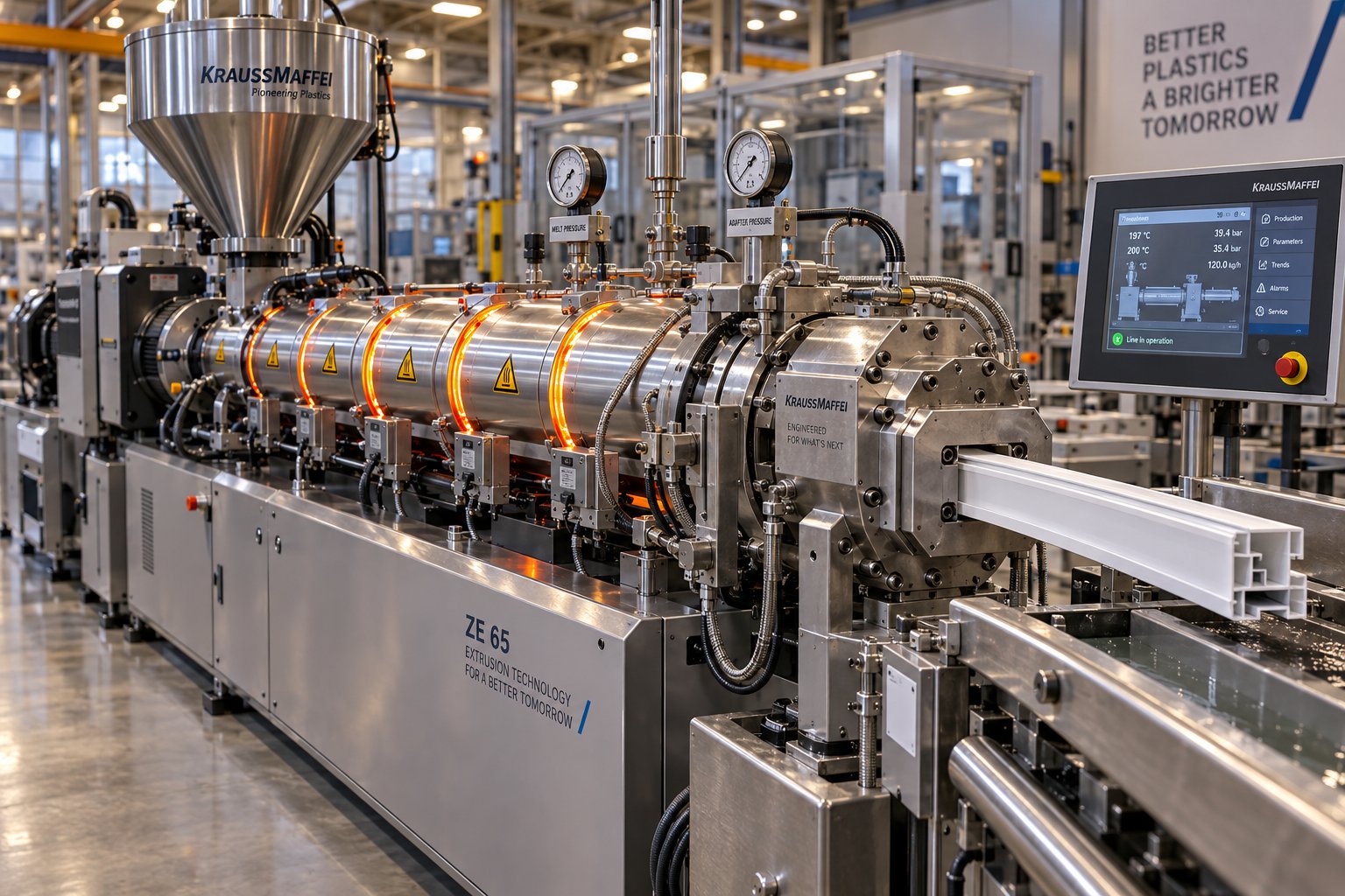
Imagine a machine that swallows raw plastic pellets at one end and delivers a perfectly shaped pipe, film, or window profile at the other — continuously, hour after hour. That is exactly what an extrusion machine does. So, what is an extrusion machine in precise terms? It is industrial equipment that melts and shapes raw material by pushing it through a profiled die under controlled heat and pressure, producing continuous lengths of product with a consistent cross-section.
What Is an Extrusion Machine
At its core, an extruder machine combines a heated barrel, a rotating screw, and a shaped die into a single mechanical system. Raw material — usually thermoplastic pellets, granules, or powder — enters through a hopper, gets melted and pressurized inside the barrel, and is then forced through the die opening. The result is an unbroken profile that can be cooled, cut, or wound into a finished product. Pipes, tubes, sheets, films, rods, and complex custom profiles all begin life this way.
While most people ask "what is a plastic extruder" and picture polymer processing, the underlying principle reaches far beyond plastics. Metal fabricators use hydraulic extrusion presses to shape aluminum and copper profiles. Rubber manufacturers rely on extruders for seals and hoses. Food processors push dough through dies to create pasta, snack pellets, and pet food. Pharmaceutical companies employ hot-melt extrusion for advanced drug-delivery systems. Even ceramic substrates follow the same push-through-a-die logic. The concept is universal; only the materials and machine details change.
Why Extrusion Machines Matter in Modern Manufacturing
Extrusion ranks among the highest-volume polymer processing methods in the world, and for good reason. It delivers continuous-length products with repeatable cross-sections at speeds that batch processes simply cannot match. A single production line can run around the clock, converting tons of raw resin into finished goods with minimal waste and consistent dimensional accuracy.
From construction piping and food packaging to automotive weatherstripping and medical tubing, the extrusion machine is the silent workhorse behind products people use every day — making it one of the most foundational pieces of equipment in modern manufacturing.
This article takes a machine-centric angle. Rather than simply describing what is an extruder machine in process terms, you'll explore every major component, compare equipment types side by side, and learn how each mechanical parameter shapes the final product. Think of it as a complete operator's map — from raw pellet to finished part — with the extruder itself at the center of the story.
How an Extrusion Machine Works Step by Step
A continuous stream of perfectly shaped plastic doesn't happen by accident. Every finished profile, pipe, or film passes through a tightly choreographed sequence inside the extruding machine — and each stage depends on the one before it. Understanding this sequence is the fastest way to diagnose problems, optimize output, and appreciate why small parameter changes upstream can ripple all the way to the finished product.
Feeding and Conveying the Raw Material
Everything starts at the hopper, the funnel-shaped reservoir mounted on top of the extruder feed barrel. Plastic pellets, granules, or powder are loaded into the hopper — either manually for small runs or via automated vacuum conveying systems for high-volume production. Gravity pulls the material down through the feed throat and into the barrel, where it meets the first flights of the rotating screw.
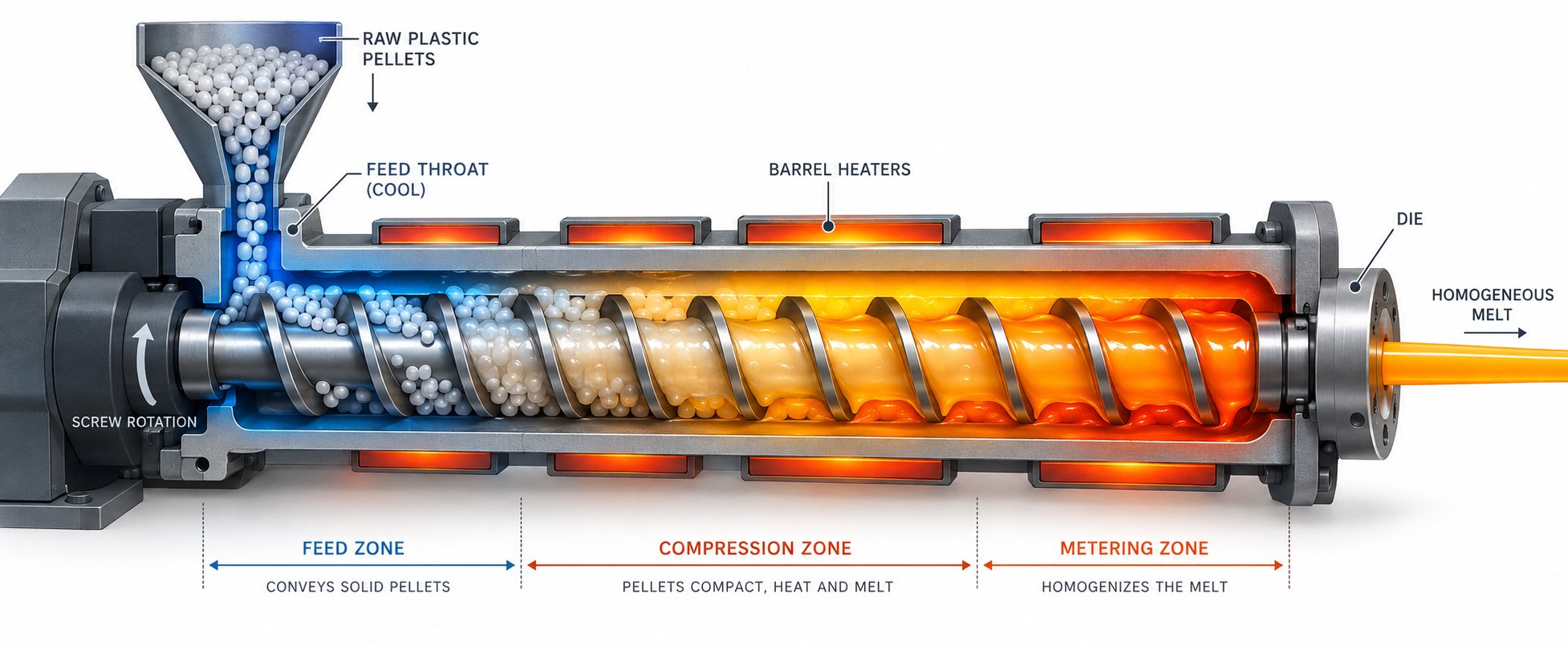
Once inside the barrel, the screw extruder takes over. The rotating screw acts like a conveyor, its helical flights catching the loose material and pushing it forward. This initial section is called the feed zone, and its channel depth is deliberately deep to accommodate the bulk density of unmelted pellets. The volume of the first flight, multiplied by screw speed and bulk density, essentially determines the machine's theoretical output rate.
Consistent feeding is more critical than it might sound. If pellets bridge inside the hopper or flow unevenly into the barrel, the result is output surging — cyclical fluctuations in throughput that show up as dimensional inconsistencies in the final product. That's why many extrusion processing machines incorporate gravimetric or volumetric feeders that meter material into the barrel at a precisely controlled rate, removing guesswork from this first and surprisingly influential step.
Melting and Metering Through the Barrel
As the screw conveys pellets deeper into the barrel, two heat sources work in tandem to melt them. External band heaters wrapped around the barrel supply conductive heat, while the mechanical shear generated by the screw's rotation creates intense frictional energy. Together, they progressively convert solid pellets into a viscous, homogeneous melt.
This transformation doesn't happen all at once. A standard screw is divided into three functional zones, each engineered for a specific purpose:
- Feed zone — Deep channel flights accept loose pellets and compact them into a dense mass called the solid bed. All trapped air between pellets must be expelled here; otherwise, it travels downstream and creates defects like gels in the finished product.
- Compression (transition) zone — The channel depth gradually decreases, squeezing the solid bed against the barrel wall. Friction between the compacted material and the hot barrel surface accelerates melting. Pressure in this zone can climb to roughly 400 bar (about 6,000 psi), driving an enormous energy transfer from screw to polymer.
- Metering zone — By this point, the polymer is nearly or fully molten. The shallow, constant-depth channel in this zone serves as a precision pump, ensuring uniform melt temperature and steady pressure before the material exits the barrel. Poor metering leads directly to pressure fluctuations at the extrusion die — and that means inconsistent wall thickness or surface finish on the final product.
You'll notice that the screw does far more than simply transport material. It compacts, melts, mixes, and pressurizes — all within a single rotating component. That's why screw geometry is often called the heart of every extrusion machine, a topic explored in detail in the next section.
Die Shaping, Cooling, and Downstream Finishing
Once the melt leaves the metering zone, it passes through a screen pack and breaker plate that filter out contaminants and help build uniform back-pressure. From there, the homogeneous melt is forced into the extrusion die — the component that gives the product its final cross-sectional shape. Annular dies produce pipes and blown film, flat dies create sheets and cast film, and custom profile dies shape everything from window frames to weatherstripping.
Shaping is only half the story. The hot extrudate emerging from the die is still soft and dimensionally unstable, so downstream equipment immediately takes over. The cooling method depends entirely on the product type: pipes and profiles typically pass through water baths or vacuum sizing tanks, blown film is cooled by an air ring as the bubble rises vertically, and flat sheet runs across temperature-controlled chill rolls. Calibration tooling locks in precise outer dimensions during cooling, while a puller draws the extrudate through the line at a carefully regulated speed — because even a slight mismatch between puller speed and extruder output will stretch or compress the product beyond tolerance.
Finally, the solidified product reaches the end of the line, where it is either cut to length by an automated saw or wound onto rolls, depending on the application. The entire journey — from loose pellets in the hopper to a finished, dimensionally accurate product — is continuous and can run for hours or even days without interruption.
For quick reference, here is the complete operational sequence of extrusion processing machines laid out as a numbered list:
- Feeding — Raw material enters the hopper and drops into the barrel.
- Conveying — The rotating screw moves pellets forward through the feed zone.
- Melting — Shear heat and barrel heaters progressively convert solids to melt in the compression zone.
- Metering — The metering zone delivers uniform melt temperature and pressure.
- Die shaping — Molten polymer is forced through the die to form the desired cross-section.
- Cooling — Water baths, air rings, or chill rolls solidify the extrudate while preserving shape accuracy.
- Pulling and calibrating — Downstream pullers and calibration tooling control speed and final dimensions.
- Cutting or winding — The finished product is cut to length or wound onto rolls for shipment.
Each of these eight stages is only as strong as the hardware behind it. The screw's geometry dictates melting efficiency, the drive system supplies the torque, and the die assembly defines the product profile. Individually, these components are impressive feats of engineering; together, they form a single, interdependent mechanical system — one worth examining piece by piece.
Core Components of Every Extrusion Machine Explained
A well-tuned extrusion line can look deceptively simple from the outside — pellets go in, finished product comes out. But strip away the covers, and you'll find a precisely engineered assembly where every component influences every other. The screw's geometry determines how much torque the gearbox must deliver. The barrel's heating zones dictate what the control panel needs to monitor. The screen changer's resistance shapes the pressure the die assembly experiences. Understanding each component individually is the key to understanding the system as a whole.
Hopper, Barrel, and Screw Assembly
The hopper is the machine's material entry point — a funnel-shaped reservoir that holds plastic pellets, granules, or powder and gravity-feeds them into the barrel below. Sounds straightforward, but material handling challenges start right here. Pellets with wide particle size distributions can compress prematurely in square hoppers, and low-bulk-density powders risk trapping air pockets that later cause defects in the extrudate. That's why many production lines add gravimetric feeders (which meter material by weight) or volumetric feeders (which meter by volume) to ensure a steady, predictable flow into the feed throat. Vibrating pads or stirring devices inside the hopper further prevent bridging — the arch-shaped blockage that starves the screw of material and triggers output surging.
The barrel is a hardened steel cylinder with a precision-machined bore that houses the screw and serves as the primary containment vessel for the entire melting and pressurizing process. Multiple independent heating and cooling zones run along its length, each controlled separately to establish a precise temperature profile from feed throat to discharge end. A water-cooled feed throat section prevents premature melting at the entry point — critical because softened pellets would stick to metal surfaces and restrict material flow. Barrels are typically manufactured from nitrided steel or lined with bimetallic alloys to resist the abrasive and corrosive effects of filled or reinforced polymers, extending service life under demanding conditions.
Then there's the extruder screw — widely considered the most important component of the entire machine. At its simplest, the extrusion screw is a cylindrical shaft wrapped in helical flights, but every dimension of its geometry carries processing consequences. Three key parameters define screw behavior:
- Flight depth — The distance from the flight tip down to the screw root. Deeper flights in the feed zone accommodate bulky, unmelted pellets; shallower flights in the metering zone compress and pressurize the melt. As NC State Extension research notes, channel depth decreases in the order: conveying zone > compression zone > metering zone.
- Pitch — The distance between two consecutive flights. Increasing pitch increases shear input into the raw material, which accelerates melting but also raises melt temperature — a trade-off that must be managed carefully for heat-sensitive polymers.
- Compression ratio — The ratio of feed zone channel depth to metering zone channel depth. This single number governs how aggressively the screw compresses the polymer as it transitions from solid pellets to homogeneous melt. A typical general-purpose ratio falls between 2.5:1 and 3.5:1, but specific resins and applications demand tailored ratios for optimal melting efficiency and mixing quality.
Extruder screws are commonly machined from medium carbon steel, though stainless steel, tool steel, and nickel-based alloys appear in corrosive or highly abrasive applications. The radial clearance between screw flight tip and barrel bore is remarkably tight — typically a ratio of about 0.001 relative to screw diameter. Even small increases in this clearance due to wear degrade output consistency and energy efficiency, which is why regular measurement of screw and barrel dimensions is a cornerstone of preventive maintenance.
Configuring a plastic extruder screw is, as one research team put it, "a blend of art and science." No universal profile works for all materials, because every polymer exhibits unique flow properties influenced by temperature, shear rate, and machine geometry. An ideal screw profile efficiently pumps material, breaks agglomerates, homogenizes the melt, and develops appropriate temperature and pressure at the die — all without degrading heat-sensitive resins or leaving unmelted particles behind.
Drive System and Gearbox
The motor and extruder gearbox form the powertrain of the extrusion machine, converting electrical energy into the torque and rotational speed required to turn the screw against viscous polymer resistance. Most modern systems use AC motor drives, though DC and hydraulic drives still appear in certain legacy installations.
Here's why gearbox selection matters more than many operators realize: the torque demand in extrusion is driven primarily by the viscous resistance of the polymer melt film between screw flights and the barrel wall — not by simple mechanical friction. Higher-viscosity materials and mineral-filled compounds increase this resistance substantially. Peak torque during startup with cold material can exceed steady-state running torque by 20-40%, meaning the gearbox must handle transient loads far above normal operating conditions.
Gearbox quality directly affects energy efficiency, operational noise, and long-term reliability. A three-stage gearbox with 97% efficiency per stage delivers only about 91% overall efficiency — the remaining 9% becomes heat that the lubrication system must dissipate. Undersized cooling shortens oil life, oxidized oil accelerates bearing wear, and the resulting failure cascade can sideline a production line for days. Beyond torque transmission, the gearbox also houses thrust bearings that absorb the axial force generated by die-head back-pressure pushing the screw rearward. In twin-screw applications, these thrust loads can range from 2.5 kN for small machines to 3,400 kN for large production units, making thrust bearing capacity a frequent life-limiting factor.
Heating and Cooling Zones and Control Panel
Precise temperature management across the barrel is essential for producing defect-free extrudate. Barrel zone heaters — typically ceramic band heaters or cast aluminum heaters — wrap around the outside of the barrel in individually controlled sections. Each zone is set to a specific temperature target, creating a graduated thermal profile that guides the polymer from solid to melt. Electric heating dominates modern extrusion lines because it is efficient, inexpensive to maintain, and operates across a wide temperature range. Fluid heating offers more uniform temperature distribution but is limited to applications below roughly 250 degrees Celsius and requires bulkier, costlier infrastructure.
Heating alone isn't sufficient, though. The mechanical shear generated by the rotating screw contributes 70-80% of the total energy input to the polymer. That frictional heat can push localized melt temperatures above the setpoint, risking thermal degradation. Cooling systems — forced-air blowers on many standard extruders, or liquid-cooled jackets on high-output machines — counterbalance this excess heat and keep each zone within its target window.
The control panel ties everything together. It serves as the operator interface for setting temperature profiles across all barrel zones, adjusting screw speed (RPM), and monitoring live data from pressure transducers and thermocouples embedded in the barrel and near the die. Modern panels range from basic PLC-based controllers with digital readouts to touchscreen HMI systems capable of storing recipes, logging process data, and triggering alarms when pressure or temperature drifts beyond acceptable limits. Accurate thermocouple calibration and responsive control loops are non-negotiable — a thermocouple reading even a few degrees off target can cause the controller to over-correct, producing temperature swings that show up as surface defects or dimensional variations in the finished product.
Die Assembly and Screen Changer
The die assembly is the component that defines the final product shape. Every cross-section you see in an extruded product — round pipes, flat sheets, complex window profiles, thin-walled tubing — originates from a carefully engineered die opening. The die must distribute molten polymer evenly across its full cross-section so that the extrudate exits with uniform wall thickness and no weld lines. Extrusion dies come in an enormous range of configurations: annular dies for pipes and blown film, flat T-dies and coat hanger dies for sheet, spiral mandrel dies for multi-layer film, and custom profile dies for specialty shapes. When the die geometry doesn't match the extruder barrel outlet directly, an adapter connects the two.
Upstream of the die sits the screen changer — or, in simpler setups, a breaker plate fitted with a screen pack. This filtration device serves two important functions. First, it removes contaminants, gels, and foreign particles from the melt stream, protecting the die from clogging and preventing defects in the extrudate. Second, it helps build consistent back-pressure, which contributes to melt homogeneity. Screen packs typically consist of layered wire mesh — coarser screens supported by the breaker plate with finer screens stacked on top. For high-contamination feedstocks like recycled resins, the screens clog faster and require frequent replacement. Automatic hydraulic screen changers allow operators to swap screen packs without shutting down the extruder, maintaining continuous production and monitoring pressure drop across the filter as the trigger for each change.
The breaker plate also serves a less obvious but equally important function: it interrupts the helical flow pattern imparted by the screw, converting spiraling melt into a straight-line flow before it enters the die. Without this correction, the spiral motion could propagate through the die and distort the extrudate's shape.
For quick reference, here is a summary of every major component in a typical extrusion machine:
- Hopper — Material entry reservoir; may include gravimetric or volumetric feeders
- Feed throat — Water-cooled transition between hopper and barrel
- Barrel — Hardened steel cylinder housing the screw; segmented into heating and cooling zones
- Extruder screw — Helical-flighted shaft responsible for conveying, melting, mixing, and pressurizing
- Motor and gearbox — Powertrain delivering torque and rotational speed to the screw; absorbs axial thrust
- Thrust bearing assembly — Resists back-pressure-induced axial loads on the screw
- Barrel heaters — Ceramic band or cast aluminum elements establishing zone temperature profiles
- Cooling system — Forced-air blowers or liquid-cooled jackets preventing localized overheating
- Control panel — Operator interface for temperature, speed, and pressure monitoring
- Breaker plate and screen pack — Filtration and flow-straightening device upstream of the die
- Screen changer — Automated or manual system for replacing clogged screen packs during operation
- Die assembly — Shaped tooling that defines the final product cross-section
Every item on that list interacts with the others. Change the screw geometry, and the gearbox torque demand shifts. Alter the die design, and the barrel temperature profile needs recalibration. Swap in a finer screen pack, and back-pressure rises across the entire system. That interdependence is exactly why experienced operators think of an extrusion machine not as a collection of parts, but as a single, integrated mechanical system — and why the type of extruder you choose shapes every specification that follows.
Types of Extrusion Machines Compared
Choosing the right extruder type is arguably the single most consequential decision in any extrusion project. The screw configuration you select dictates mixing intensity, material compatibility, throughput potential, and capital cost — all before a single pellet enters the hopper. Yet information on these differences tends to be scattered across manufacturer brochures, each emphasizing its own product. Here's a consolidated, side-by-side look at every major category.
Single Screw Extruder Characteristics and Applications
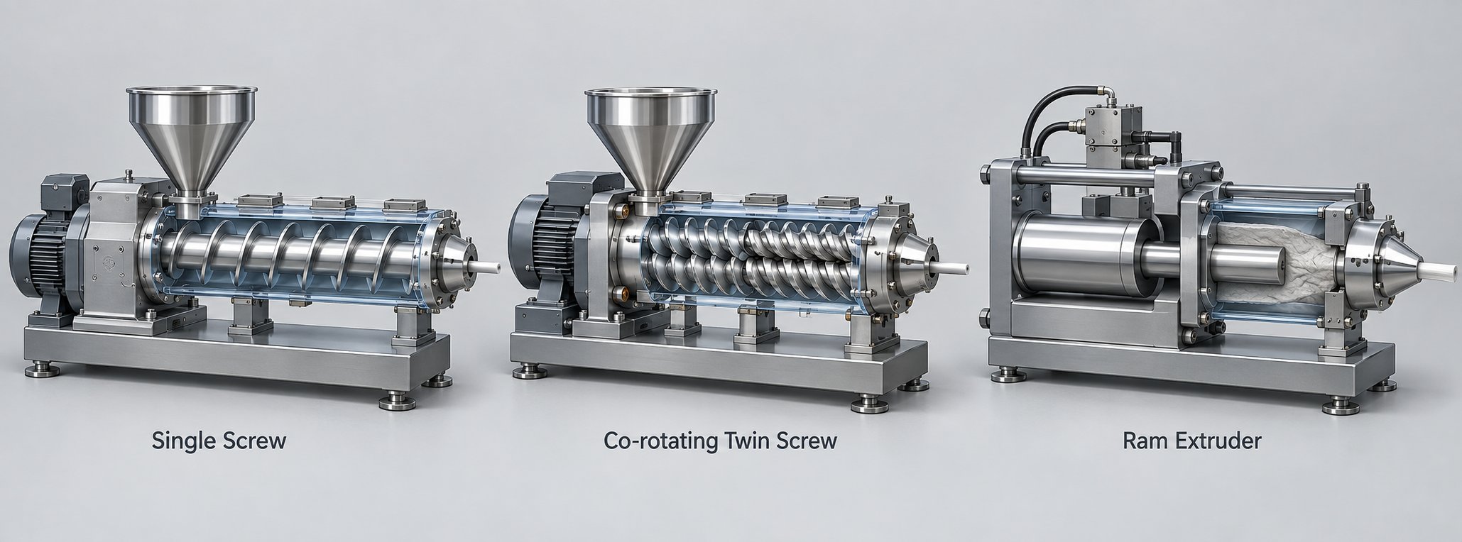
The single screw extruder is the workhorse of the plastics industry — and the most widely installed type worldwide. Its design is elegantly straightforward: one rotating screw inside one barrel, progressing material through the feed, compression, and metering zones covered earlier. That simplicity translates into lower purchase price, easier operation, and reduced maintenance compared to multi-screw alternatives.
Where does a single screw extruder machine truly shine? When you're processing pre-compounded resins that don't require intensive mixing. Pipe, profile, sheet, blown film, and wire coating lines overwhelmingly rely on single-screw designs because the material arrives ready to melt and shape. The screw does its job — convey, melt, pressurize — and the die does the rest. For processors running a single resin family at steady volumes, a well-configured single-screw setup often represents the best balance of output consistency, energy efficiency, and cost per kilogram of product.
The trade-off? Limited mixing capability. A single screw relies primarily on drag flow and shear between the flight tip and barrel wall. If your application demands blending multiple additives, dispersing fillers, or reacting components in-line, you'll quickly hit the ceiling of what this configuration can deliver.
Twin Screw Extruder Advantages for Compounding and Mixing
When mixing intensity and process flexibility take priority, the twin screw extruder steps in. Two intermeshing screws inside a figure-eight barrel bore create flow fields that a single screw simply cannot replicate. The category splits into two distinct configurations, each suited to different processing challenges.
Co-rotating twin screw extruders — where both screws turn in the same direction — dominate compounding, masterbatch production, and reactive extrusion. Their fully intermeshing, self-wiping geometry forcibly transfers material from one screw to the other at the intermeshing zone, generating intense distributive and dispersive mixing. As Technovel's technical analysis explains, the self-wiping action suppresses stagnation and keeps the residence time distribution narrow, which is critical for heat-sensitive polymers and reactive processes. Modular screw designs let engineers place kneading blocks, mixing elements, and conveying elements exactly where needed, giving precise control over energy input along the barrel.
Counter-rotating twin screw extruders — screws turning in opposite directions — take a fundamentally different approach. Material is drawn into the intermeshing region and advanced under compression rather than high shear. This produces a calendering effect that disperses additives under gentle conditions while keeping melt temperatures low. The result is a thermoplastic extruder configuration ideally matched to rigid PVC, which has a notoriously low thermal decomposition temperature. PVC pipe, sheet, and profile extrusion lines worldwide rely on counter-rotating designs for exactly this reason.
Ram Extruders and Specialty Configurations
Not every material flows willingly through a screw channel. Highly viscous polymers like PTFE, certain rubbers, and ceramic pastes resist the drag-flow mechanism that screw extruders depend on. Ram (plunger) extruders solve this by using a hydraulic piston to force material through the die in discrete batches. The trade-off is obvious — batch operation instead of continuous output — but for materials that would degrade under the sustained shear of a rotating screw, ram extrusion is often the only viable path.
Planetary roller extruders represent another specialty design worth knowing. A central screw is surrounded by multiple smaller planetary screws that orbit inside a toothed barrel, creating extremely high surface renewal rates and excellent temperature control. These machines handle heat-sensitive formulations — certain PVC compounds, adhesives, and thermoplastic elastomers — where conventional twin-screw shear would risk degradation. Their throughput-to-footprint ratio is impressive, though capital cost and mechanical complexity are higher than standard polymer extruder configurations.
The table below consolidates these comparisons into a single reference. Whether you're evaluating the best extruders for thermoplastics, rubber, or specialty materials, this matrix highlights the key differentiators at a glance.
| Type | Screw Configuration | Mixing Capability | Typical Applications | Relative Cost | Throughput Range |
|---|---|---|---|---|---|
| Single Screw Extruder | One screw in cylindrical barrel | Low to moderate — relies on drag flow and shear | Pipe, profile, sheet, blown film, wire coating | Low | 5 – 1,500+ kg/hr |
| Co-Rotating Twin Screw | Two intermeshing screws, same direction | High — self-wiping, modular kneading elements | Compounding, masterbatch, reactive extrusion, devolatilization | Medium to High | 5 – 2,500+ kg/hr |
| Counter-Rotating Twin Screw | Two intermeshing screws, opposite directions | Moderate — calendering effect, low shear | PVC pipe, PVC profile, PVC sheet extrusion | Medium | 50 – 1,500 kg/hr |
| Ram (Plunger) Extruder | Hydraulic piston, no screw | Minimal — batch processing only | PTFE, rubber, ceramics, high-viscosity specialty polymers | Low to Medium | Batch-dependent |
| Planetary Roller Extruder | Central screw + orbiting planetary screws | Very high — extreme surface renewal | Heat-sensitive PVC, adhesives, TPE, specialty compounds | High | 50 – 5,000+ kg/hr |
Every row in that table represents a different set of engineering trade-offs — cost versus mixing, throughput versus shear sensitivity, simplicity versus flexibility. The right choice depends entirely on what material you're processing and what product you need at the end of the line. That product-driven perspective is exactly where the discussion heads next: how extruders across these categories serve vastly different industries, from plastic packaging to pharmaceuticals.
Extrusion Machine Applications Across Industries
A single-screw extruder running polyethylene film and a hydraulic press shaping aluminum curtain wall profiles look nothing alike on the factory floor — yet both rely on the same fundamental principle of forcing material through a die. The diversity of extrusion machine types explored above exists precisely because the range of applications is enormous. Here's where theory meets production reality.
Plastic Film, Sheet, and Pipe Extrusion
Plastics account for the largest share of extrusion activity worldwide, and the product categories within this space alone are staggeringly diverse.
Blown film lines use an annular die mounted vertically on the extruder. Molten polymer exits the die as a thin tube, which is inflated by internal air pressure into a bubble and cooled by an air ring as it rises. The collapsed bubble yields a continuous lay-flat film used in grocery bags, agricultural mulch, shrink wrap, and flexible food packaging. A modern blown film machine can produce three to nine co-extruded layers in a single pass, each layer engineered for barrier performance, seal strength, or printability. Blown extrusion film remains one of the highest-volume segments of the packaging industry, processing materials like LDPE, LLDPE, and HDPE at outputs exceeding 500 kg/hr on large-scale lines.
Cast film and sheet extrusion take a different approach. A flat T-die — or coat hanger die — spreads the melt horizontally across polished chill rolls, producing sheet or film with excellent thickness uniformity and optical clarity. A pp sheet extrusion line, for example, produces rigid PP sheets destined for thermoforming into cups, trays, and clamshell packaging. Multi-manifold flat dies can layer different polymers with precise thickness control — outperforming blown film dies when optical transparency and tear resistance are critical.
Pipe extrusion rounds out the trio. A plastic pipe extrusion machine pairs the extruder with a circular die, vacuum sizing tank, spray cooling bath, haul-off unit, and planetary cutter. The pipe extruder shapes PVC, HDPE, and PPR into water supply pipes, gas distribution lines, drainage conduits, and irrigation tubing. Pipe diameters range from a few millimeters for medical tubing to over one meter for municipal infrastructure — each size requiring matched die tooling and downstream calibration equipment.
Profile Extrusion and Wire Coating Applications
Imagine the cross-section of a vinyl window frame — the hollow chambers, the snap-fit channels, the thin walls all formed in a single continuous pass. That's profile extrusion at work. Custom die shapes, often requiring extensive flow simulation during design, enable production of window profiles, door frames, weatherstripping, edge banding, cable ducts, and complex architectural trim. Because these shapes are far more geometrically demanding than round pipes or flat sheets, profile dies are among the most engineering-intensive components in the entire extrusion ecosystem.
Wire and cable coating represents another specialized branch. In this process, a bare conductor — copper, aluminum, or fiber-optic strand — is fed through a crosshead die mounted perpendicularly to the extruder barrel. Molten polymer flows around the conductor inside the die, depositing a uniform insulating jacket as the wire exits at high speed. A wire cable extrusion machine typically pairs a precision single-screw extruder with inline spark testers, diameter gauges, and tension-controlled take-up reels to guarantee electrical insulation integrity across thousands of meters per hour.
Beyond Plastics — Food, Pharma, Rubber, and Metals
Extrusion's reach extends well past the polymer world. The same push-through-a-die logic adapts to an impressive range of materials and sectors:
- Food processing — Twin-screw extruders cook and shape snack pellets, breakfast cereals, pasta, and pet food. The combination of heat, pressure, and moisture inside the barrel gelatinizes starches and denatures proteins, creating expanded textures in a single continuous step.
- Pharmaceuticals — Hot-melt extrusion disperses active pharmaceutical ingredients into polymer carriers, improving drug solubility and enabling controlled-release tablet and implant formulations. Co-rotating twin-screw machines dominate this space due to their precise residence-time control.
- Rubber — Cold-feed and hot-feed rubber extruders produce seals, gaskets, hoses, tire tread strips, and automotive weatherstripping. Pin-barrel designs enhance mixing of carbon black and curing agents into natural and synthetic rubber compounds.
- Metals — Hydraulic extrusion presses force heated aluminum, copper, or steel billets through hardened steel dies to create structural profiles, heat-sink sections, and railing systems. Aluminum extrusion alone supplies industries from aerospace and automotive to construction and electronics.
- Ceramics — Piston and screw extruders shape ceramic pastes into honeycomb filter cores, catalyst substrates, and kiln furniture before sintering.
What connects every item on this list is a shared engineering challenge: matching machine parameters — screw design, temperature profile, die geometry, and downstream cooling — to the specific material and product requirements. That relationship between configuration and outcome is far more nuanced than most operators realize, and it's where small upstream adjustments create measurable downstream differences.
How Machine Configuration Shapes Product Quality
Every extrusion operator has seen it: two seemingly identical production lines running the same resin, yet one delivers flawless output while the other struggles with surface defects and dimensional drift. The difference rarely comes down to a single dramatic failure. Instead, it's the cumulative effect of dozens of parameter choices — screw geometry, barrel temperature profiles, die pressure stability, cooling rates, puller speeds — interacting as a system. Understanding how each setting translates into a tangible product characteristic is what separates routine operation from true process mastery.
How Screw Design Influences Melt Quality
The screw isn't just a conveyor. Its geometry is the single largest determinant of melt homogeneity — and melt homogeneity is the single largest determinant of finished product consistency. Three screw parameters carry the most weight in this relationship.
L/D ratio (length-to-diameter ratio) controls how long the polymer stays inside the barrel. A longer screw — say 30:1 versus 24:1 — gives the material more time and more mechanical energy input for melting and mixing. As GS Extruder's analysis of screw parameters explains, enhanced L/D ratios combined with optimized thermal gradients facilitate superior polymer blending and plasticization. The trade-off? Excessive length increases energy consumption, raises the risk of shaft deflection, and can degrade thermally sensitive polymers like PVC through prolonged residence time.
Compression ratio — the ratio of feed zone channel depth to metering zone channel depth — dictates how aggressively the screw compacts and densifies the polymer. A higher compression ratio forces more intimate contact between pellets and the barrel wall, accelerating heat transfer and producing a denser, more uniform melt. But push the ratio too high for a given resin, and you'll generate excessive shear heating that degrades molecular weight and discolors the extrudate.
Flight depth in the metering zone acts as a fine-tuning lever. Shallower metering flights generate higher shear rates, improving mixing and heat distribution within the melt — but they also reduce channel volume, which limits throughput. Deeper flights move more material per revolution while sacrificing some mixing intensity. The optimal balance depends entirely on the polymer's viscosity profile and the product's quality requirements.
Here's where things get practical: a poorly matched screw produces what operators call "unmelts" — solid or semi-solid particles embedded in an otherwise molten stream. These unmelts travel through the die and show up as surface roughness, weak spots, or visible inclusions in the finished product. Dimensional inconsistency follows close behind, because uneven melting creates localized viscosity differences that cause the extrudate to flow unevenly through the die opening.
Screw wear compounds the problem over time. As the clearance between the flight tip and barrel bore widens — even by fractions of a millimeter — backflow increases, pressure stability drops, and the screw's ability to generate consistent shear diminishes. The result is a gradual, sometimes imperceptible decline in output quality that accelerates if left unchecked. Automated extrusion equipment with real-time monitoring can flag these trends early, but regular physical measurement of screw and barrel dimensions remains the gold standard for wear detection.
Temperature Profiles, Pressure Control, and Dimensional Accuracy
Imagine baking bread in an oven where each shelf runs at a different temperature — that's essentially how barrel zone heating works. Each zone along the barrel is set to a specific target, creating a thermal gradient that guides the polymer from solid pellets at the feed end to a fully homogeneous melt at the die. The trick is that these setpoints can't be chosen in isolation. They must be tuned to the specific polymer and the specific product being made.
As Plastics Technology's Jim Frankland emphasizes, Zone 1 is particularly critical. Setting it too far below the polymer's melting point delays melt-film formation and effectively shortens the melting length of the screw. Setting it too far above the melting point lowers film viscosity, reducing the frictional drag that drives melting. In either case, you lose output and melt quality — the opposite of what most operators intend when they tweak Zone 1. A good starting point is a temperature slightly above the polymer's melting point, which initiates the melt film without collapsing the viscosity that sustains it.
Die pressure stability is where temperature control meets dimensional accuracy. Consistent melt pressure at the die means consistent flow rate through the die opening, which translates directly to uniform wall thickness and surface finish. Pressure fluctuations — even small ones — cause the extrudate to pulse, producing alternating thick and thin zones that may not be visible to the naked eye but will fail dimensional tolerance checks. Profile extrusion equipment, where complex cross-sections demand tight wall-thickness uniformity across multiple channels, is especially sensitive to pressure variation.
The screen changer plays a supporting but underappreciated role here. As screens load with contaminants, the pressure drop across the filter rises, subtly shifting the pressure profile upstream. On automated extrusion systems, sensors trigger a screen change before this drift becomes significant. On manual systems, operators who wait too long between changes often see a sudden pressure spike followed by a brief surge in output when the fresh screen is inserted — each event leaving its mark on the extrudate as a localized dimensional deviation.
Downstream Equipment and Final Product Characteristics
Everything upstream — screw design, temperature profile, die pressure — produces a hot, dimensionally unstable extrudate. The downstream extrusion equipment is what locks in the final product properties.
Cooling rate is the first lever. Rapid quenching in a water bath or against chill rolls freezes the polymer's molecular structure quickly, typically producing an amorphous (non-crystalline) structure with higher transparency but lower stiffness. Slower, more controlled cooling allows crystalline regions to develop, increasing mechanical strength and chemical resistance at the expense of optical clarity. Choosing the right cooling rate — and matching it to the polymer type — is as important to the finished product as any upstream parameter.
Puller speed is the second lever. The puller draws the extrudate through all downstream stations at a precisely controlled rate. Even minor mismatches between puller speed and extruder output stretch or compress the product, altering wall thickness, outer diameter, and internal dimensions. As Conair's auxiliary equipment guide notes, minute adjustments in puller speed during forming and cooling enable fine-tuning of dimensional characteristics like wall thickness and internal diameter — a capability that's essential for maintaining tolerance on medical tubing, precision profiles, and thin-wall pipe.
Calibration tooling completes the picture. Vacuum sizing sleeves, sizing plates, or calibration mandrels physically constrain the extrudate's outer dimensions as it cools and shrinks. Without proper calibration, thermal contraction produces unpredictable shape changes that no amount of upstream optimization can correct. The tooling must match the target product dimensions after accounting for die swell (the extrudate's tendency to expand beyond die dimensions upon exiting) and thermal shrinkage — both of which vary by polymer and cooling conditions.
Extrusion machine configuration is inseparable from end-product quality. Every parameter choice upstream — from screw compression ratio to barrel Zone 1 temperature to screen-change frequency — manifests in the finished product downstream as a measurable property: wall thickness, surface finish, crystallinity, mechanical strength, or dimensional tolerance.
This cause-and-effect chain running from plastic extrusion tooling through plastic compounding equipment and all the way to the packaged product is what makes extrusion both challenging and rewarding. Get the configuration right, and the line runs for days with minimal intervention. Get it wrong, and the symptoms multiply — which raises an important practical question: when things do go wrong, how do you trace the defect back to its root cause?
Common Extrusion Machine Problems and How to Fix Them
Defects rarely announce themselves with a single, obvious alarm. More often, they creep in — a slight wall-thickness drift here, a faint surface roughness there — until scrap rates climb and someone finally asks what changed. The truth is that most extrusion problems fall into a surprisingly short list of categories, and each one leaves a diagnostic signature if you know where to look. Whether you're running a dedicated plastic extruder for virgin resin or a plastic recycling extruder machine processing post-consumer flake, the failure modes below will look familiar.
Output Instability and Surging
Surging is the cyclical rise and fall of output rate — picture a pipe whose wall thickness pulses between thick and thin every few minutes. You can often spot it on the pressure transducer before it becomes visible on the product: a rhythmic oscillation, typically at intervals of one to five minutes, that corresponds to fluctuations in melt delivery to the die.
What causes it? Three culprits account for the vast majority of cases:
- Inconsistent feeding — Pellets bridging inside the hopper or uneven bulk density in recycled plastic extruder blends starve the screw intermittently, creating gaps in the solid bed that translate to output swings downstream.
- Worn screw flights — As the clearance between flight tip and barrel bore widens, backflow over the flights increases. The screw loses pumping efficiency, and output becomes erratic — especially at lower speeds where drag flow dominates.
- Improper feed-zone temperature — A feed throat that's too warm allows premature melting, which forms a sticky film on the barrel wall and disrupts the solid-bed conveying mechanism. A feed throat that's too cold can restrict pellet flow.
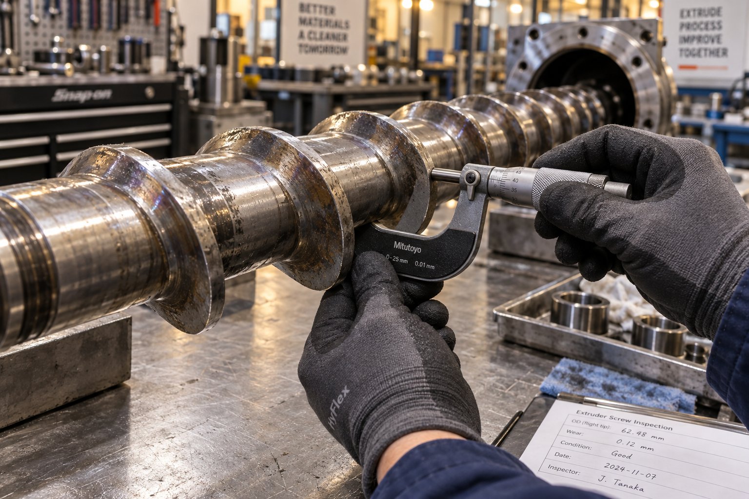
Diagnostic steps are straightforward: check for hopper bridging first (tap the hopper wall and watch the pressure trace for a response), then inspect the screw for wear using a micrometer at the flight tips, and finally verify that feed-throat cooling water is flowing at the correct temperature and rate. Cofit's pressure instability analysis confirms that screw surging is the second most common cause of melt pressure variation on general-purpose extrusion lines, making it a priority for any operator tracking dimensional drift.
Melt Quality Defects and Pressure Fluctuation
Even when output volume is stable, the quality of the melt itself can undermine the finished product. Three defects dominate this category:
Melt fracture — often called "sharkskin" — appears as a rough, ridged surface on the extrudate. It occurs when the polymer's elastic stress at the die exit exceeds a critical threshold, causing the melt surface to fracture as it flows past the die lip. Raising melt temperature, increasing the die gap, or adding a polymer processing additive (PPA) can reduce die-lip shear stress and eliminate the defect. Davis-Standard's troubleshooting guide recommends raising die-lip temperature as a first corrective step, with PPA addition as a last resort.
Die swell — the extrudate expanding beyond the die dimensions — is normal to a degree, but excessive swell indicates stored elastic energy from insufficient relaxation time in the metering zone or die land. Lengthening the die land or reducing extrusion speed gives the melt more time to relax before it exits.
Gels and unmelts result from poor mixing or degraded polymer fragments. These defects are especially common on extruder machines processing recycled feedstock, where contamination levels and melt-flow-index variability are inherently higher than with virgin resin. A waste plastic extrusion machine handling post-consumer material, for instance, faces higher gel counts than a virgin-resin line simply because the incoming material is less homogeneous. Inspect the screw for worn mixing sections and verify that screen packs are being changed frequently enough to capture degraded particles before they reach the die.
Pressure fluctuation at the die ties all of these issues together. SPE data shows that +/-5% melt pressure variation upstream of the die produces roughly +/-3 to 5% gauge variation in sheet and film products — enough to push product outside thermoforming tolerances for food packaging applications. Monitoring the die-inlet pressure transducer continuously, rather than checking it periodically, is the single most effective way to catch upstream problems before they reach the finished product.
Overheating, Degradation, and Blockage
Polymer degradation is the silent killer of extrusion quality. Excessive barrel temperatures — or, more insidiously, excessive shear heating from a mismatched screw design — push the melt beyond the polymer's thermal stability window. The molecular chains break down, releasing volatile byproducts that appear as discoloration, black specks, or a burnt smell at the die. Mechanical properties suffer too: degraded polyethylene loses impact strength; degraded PVC releases hydrochloric acid that corrodes barrel and screw surfaces. According to rheological data published by SPE, a 10 degrees Celsius barrel temperature variation can produce a 15 to 30% change in melt viscosity for common polyolefins — a swing large enough to destabilize the entire process.
Blockages are the mechanical counterpart to thermal degradation. Contaminated feedstock — common when running a plastic recycling extruder — accelerates screen pack blinding, which progressively restricts melt flow and forces the extruder to work harder against rising back-pressure. Die buildup from degraded polymer accumulating at the lip restricts the exit further. Both problems share the same pressure signature: a gradual upward drift in die-inlet pressure, followed by a step drop when the operator intervenes to clean or replace the blocked component. Scheduling screen changes based on differential pressure trends rather than fixed time intervals, as Bojing's maintenance guide recommends, prevents most blockage-related quality losses before they escalate.
Many of these problems — surging from worn flights, unmelts from degraded mixing sections, rising energy consumption from widened screw-to-barrel clearances — trace back to the mechanical condition of the screw and barrel. When diagnostic steps consistently point toward wear-related root causes, an expert evaluation of the screw and barrel assembly becomes the logical next action. Specialists like NANHAIYA offer practical screw barrel support for extrusion plants, recycling operations, and processing teams working through output instability, melt-quality problems, and pressure fluctuation — providing a focused resource alongside in-house diagnostic efforts.
The troubleshooting matrix below consolidates the most common problems into a quick-reference format. Bookmark it, print it, or tape it to the control panel — it covers 90% of the issues an extruder for plastic will encounter in day-to-day production.
| Problem | Symptoms | Common Causes | Recommended Action |
|---|---|---|---|
| Output surging | Cyclical wall-thickness variation; rhythmic pressure oscillation (1-5 min intervals) | Hopper bridging; worn screw flights; improper feed-throat cooling; inconsistent bulk density in recycled blends | Clear hopper obstruction; measure screw flight clearance; verify feed-throat water temperature; add gravimetric feeder for recycled feedstock |
| Melt fracture (sharkskin) | Rough, ridged, or wavy surface on extrudate | Excessive die-lip shear stress; melt temperature too low; die gap too narrow | Raise melt or die-lip temperature; increase die gap; add PPA as last resort |
| Excessive die swell | Extrudate expands well beyond die dimensions | Insufficient melt relaxation time; short die land; excessive extrusion speed | Lengthen die land; reduce screw speed; optimize metering-zone temperature |
| Gels and unmelts | Visible solid particles or gel spots in finished product | Worn mixing sections on screw; insufficient barrel temperature; contaminated or inconsistent feedstock | Inspect and measure screw; verify barrel zone temperatures; increase screen-change frequency; pre-screen recycled material |
| Pressure fluctuation | Erratic die-inlet pressure readings; inconsistent gauge in film or sheet | Screen pack saturation; screw surging; barrel temperature zone cycling; die contamination | Log screen-change times against pressure trace; inspect heater bands and thermocouples; clean die lips and manifold |
| Overheating and degradation | Discoloration; black specks; burnt odor; reduced mechanical properties | Barrel temperature too high; excessive screw shear; inadequate cooling; degraded heater-band control | Lower barrel setpoints; check thermocouple calibration; inspect cooling fans or jackets; review screw compression ratio |
| Screen pack blockage | Progressive rise in back-pressure; declining output at constant screw speed | Contaminated feedstock; degraded polymer accumulation; mesh too fine for material | Switch to pressure-triggered screen changes; pre-clean recycled input; match mesh size to contamination level |
| Die buildup and blockage | Streaks or lines on extrudate surface; localized thin spots; step-change in pressure | Polymer degradation products accumulating at die lips; thermally sensitive resin; infrequent die cleaning | Schedule die-lip cleaning before buildup reaches critical level; review die temperature profile; purge with cleaning compound |
Catching these issues early keeps scrap rates low and production uptime high. But reactive troubleshooting, no matter how skilled, is always more expensive than proactive prevention. The real leverage lies in routine maintenance — monitoring wear trends, scheduling component replacement before failure, and keeping the plastic extruder machine operating within its design envelope over the long haul.
How to Choose the Right Extrusion Machine
Keeping an extrusion line within its design envelope — the theme that closed the troubleshooting discussion — assumes you selected the right machine in the first place. A well-chosen extruder minimizes the problems you'll need to troubleshoot, while a poorly matched one turns every production day into a fight against its own limitations. The challenge is that browsing listings for a plastic extruder machine for sale can feel overwhelming when screw diameters, L/D ratios, motor ratings, and automation packages vary across dozens of configurations. Narrowing the field becomes much simpler when you work through three decisions in sequence.
Matching Machine Type to Your Material and Product
Start with the material, not the machine. What does the polymer need to undergo inside the barrel before it reaches the die?
If you're running pre-compounded pellets into a straightforward shape — pipe, sheet, film, or cable jacketing — a single screw extruder machine is almost always the practical choice. Its simpler mechanical design translates to a lower extruder machine price, easier operation, and reduced maintenance burden. Blown film extrusion machine manufacturers, custom wire extrusion machine supplier networks, and highspeed extrusion machine supplier catalogs all lean heavily on single-screw platforms for exactly this reason: when the resin arrives ready to melt and shape, one screw does the job efficiently.
The equation shifts when your process demands more than simple melting and pumping. Compounding mineral fillers, blending color masterbatch, incorporating glass fiber, or running reactive extrusion all require the intensive distributive and dispersive mixing that only a twin-screw extruder reliably delivers. Co-rotating intermeshing designs dominate compounding and masterbatch production, while counter-rotating configurations suit PVC processing where low-shear, controlled-temperature conditions prevent degradation. As Phoenix Equipment's selection guide puts it, the decision hinges on whether the machine primarily needs to convey, melt, and shape — or whether substantial material development must also occur inside the barrel.
Evaluating Throughput, Screw Diameter, and L/D Ratio
Once the extruder type is settled, sizing comes next. Two specifications carry the most weight here.
Screw diameter sets the ceiling for maximum throughput. Extrusion volume scales roughly with the square of the diameter — meaning a jump from a 60 mm to a 90 mm screw doesn't increase output by 50%, it roughly doubles it. That nonlinear relationship makes screw diameter the primary specification for matching an extruder to your production volume targets. Oversizing wastes capital and energy; undersizing forces the machine to run near its limits, accelerating wear and narrowing your process window.
L/D ratio determines how much processing length is available inside the barrel. A common range falls between 24:1 and 36:1 for single-screw machines. Longer ratios provide more residence time, more energy input, and better melting uniformity — all advantages when processing uncompounded powders or resins that require extended plasticization. Shorter ratios suit thermally sensitive materials like PVC, where prolonged barrel exposure risks degradation. Pre-pelletized materials that have already undergone some processing can often be extruded effectively with a shorter screw, while unprocessed powders benefit from the extended melting path a longer L/D provides.
Don't confuse maximum output with usable output. Throughput is influenced by screw speed, available torque, melt viscosity, die restriction, and product-quality targets. The more useful benchmark is output at your required quality level and operating stability — not the peak number printed on the datasheet.
Automation, Controls, and Total Cost Considerations
Modern extrusion equipment spans a wide automation spectrum. Entry-level machines use basic PLC controllers to manage barrel temperature zones and screw speed — adequate for single-product lines with experienced operators. Mid-range systems add recipe storage, alarm logging, and trend displays that help operators spot process drift before it becomes a quality issue. At the top end, fully integrated Industry 4.0 platforms connect the extruder to upstream feeders, downstream equipment, and cloud-based analytics, enabling remote monitoring, predictive maintenance alerts, and production reporting across multiple lines.
Automation adds upfront cost, but it also reduces human error, shortens changeover times, and generates the process data you need for continuous improvement. For facilities searching for a plastic extrusion machine for sale, the automation level should match not just today's operational complexity but the flexibility you'll need as product lines evolve.
Beyond the purchase price, total cost of ownership determines whether a machine is genuinely affordable over its working life. Industry case studies show that budget-tier extruders with lower sticker prices can accumulate significantly higher five-year costs once energy consumption, maintenance frequency, downtime losses, and reject rates are factored in. Energy alone is substantial — high-efficiency machines consuming 0.25-0.30 kWh/kg versus 0.40-0.45 kWh/kg for less efficient alternatives can save tens of thousands of dollars over five years of operation. Whether you're evaluating a modern wire extrusion equipment supplier or a general-purpose line builder, the same principle applies: the cheapest machine on the quote sheet is not always the cheapest machine to own.
Use the checklist below when evaluating any extrusion machine purchase. It captures the critical factors in a format you can bring to supplier meetings or use as a scoring template across multiple quotes.
- Material compatibility — Does the extruder type (single vs. twin screw) match your resin and processing requirements?
- Screw diameter and L/D ratio — Are they sized for your target throughput and material characteristics?
- Motor power and gearbox torque — Can the drive system handle peak startup loads and high-viscosity compounds?
- Temperature control zones — Are there enough independently controlled zones for your barrel length and process sensitivity?
- Automation and controls — Does the control system support recipe management, data logging, and alarm functions you need?
- Energy efficiency — What is the specific energy consumption (kWh/kg) for your target material at rated output?
- Spare parts availability — Can you source critical wear components (screws, barrels, heater bands) within an acceptable lead time?
- After-sales support — Does the supplier offer technical response, on-site service, and operator training?
- Downstream compatibility — Will the extruder integrate with your existing cooling, calibration, and cutting equipment?
- Total cost of ownership — Have you modeled energy, maintenance, downtime, and reject costs over a five-year horizon?
Scoring each criterion before committing to a purchase prevents the most expensive mistake in extrusion: buying a machine that fits the budget but fights the process. Yet even the best-selected equipment degrades over time — screws wear, barrels erode, gearboxes accumulate hours. How you manage that wear trajectory determines whether your line delivers consistent quality for five years or fifteen.
Maintaining Your Extrusion Machine for Long-Term Performance
A well-selected, properly configured extrusion machine can run productively for decades — but only if wear is tracked and addressed before it quietly erodes output quality. The difference between a plastic extrusion machine that holds tight tolerances at year ten and one that struggles by year three almost always comes down to maintenance discipline. Reactive repairs after a breakdown are expensive; a structured preventive program pays for itself many times over.
Preventive Maintenance Schedules and Wear Monitoring
Think of preventive maintenance as health screening for your extrusion machinery. You're looking for gradual changes that haven't yet triggered visible problems — because by the time defects show up in finished product, the underlying wear has usually progressed well past the point where a quick fix is possible.
Essential tasks fall into a predictable rhythm:
- Screw and barrel measurement — The single most important inspection on any plastic extrusion machines line. Using an inside micrometer for the barrel bore and an outside micrometer for the screw flight tips, measure at multiple points along the length and compare readings against the manufacturer's original tolerances. As Reiloy USA's preventive maintenance handbook recommends, inspect every six months when running reinforced or filled resins, and annually for unfilled materials, until wear trends are established for your specific process.
- Gearbox oil analysis — Periodic oil sampling reveals metal particle counts, viscosity changes, and oxidation levels long before bearing noise or temperature spikes signal a problem. Replacing oil on schedule — and upgrading to synthetic lubricants where operating temperatures justify it — extends gearbox life significantly.
- Heater band inspection — Ceramic band and cast aluminum heaters degrade over time. A failed heater band creates a cold spot that the adjacent zones try to compensate for, distorting the temperature profile and introducing melt-quality variation. Visual inspection and resistance checks during scheduled downtime catch failures before they cascade.
- Thermocouple calibration — Even a few degrees of drift in thermocouple readings can cause the control loop to over- or under-correct, producing temperature oscillations that show up as surface defects or dimensional variation in the extrudate. Annual calibration against a reference standard keeps readings honest.
Among all these tasks, screw and barrel wear monitoring stands out as the most impactful. Research published by Plastics Technology shows that as flight clearance widens, the extruder must run at higher screw speeds to maintain the same output rate — which raises discharge temperatures, increases energy consumption, and accelerates further wear. On a 100 mm extruder processing 1 MI polyethylene, wear that doubles the flight clearance can force a rate reduction of roughly 13% to keep discharge temperatures within a workable range. That kind of capacity loss, compounded across months of production, far outweighs the cost of timely component replacement.
As components wear, changes will appear in overall cycle times, scrap rates, energy consumption, and downtime — a strong preventive maintenance program can minimize each of these.
When to Replace or Refurbish Screw and Barrel Assemblies
Knowing when to act is just as important as knowing what to inspect. Four signals consistently indicate that a screw or barrel has reached the end of its effective service life:
- Declining throughput at constant screw speed — The clearest sign that backflow over worn flight tips is stealing pumping efficiency. If you find yourself increasing RPM just to hold rate, wear is the likely culprit.
- Increasing melt temperature variation — Wider clearances reduce the heat-transfer coefficient at the barrel wall, causing discharge temperatures to climb unevenly. Products sensitive to thermal history — blown film, medical tubing, optical sheet — show this effect first.
- Rising energy consumption — A worn screw converts more motor power into heat rather than forward pressure, driving up the specific energy (kWh/kg) for the same output. Tracking this metric over time provides an objective, numbers-based trigger for replacement.
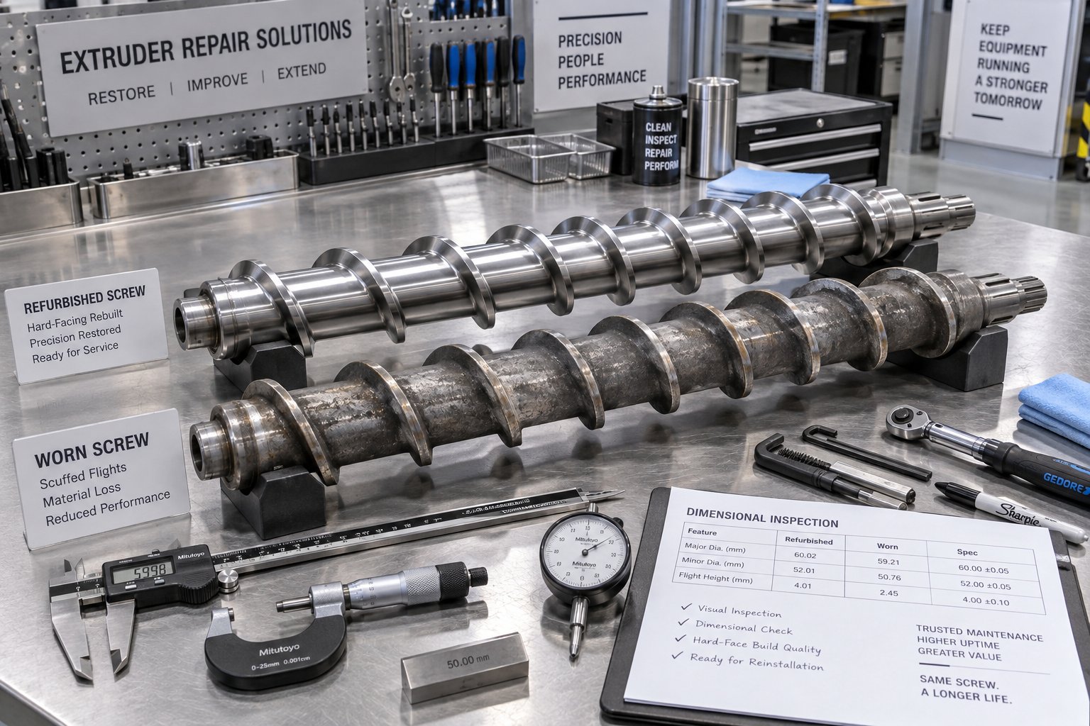
- Visible surface wear — Hard facing worn through to base metal on the flight tips, scoring on the barrel bore, or measurable clearance beyond the 4x-new threshold cited by industry guidelines all warrant action. Critical-duty processes like medical extrusion may justify replacement at just 2x the original clearance.
Replacement isn't always the only option. Refurbishment can restore a high-performance extrusion machine to near-original condition at a fraction of the cost of a new screw or barrel. Common refurbishment methods include:
- Re-nitriding — Restoring the hardened surface case on nitrided screws that have worn through the original treatment. Effective for screws processing clean, unfilled resins.
- Hard-facing (PTA welding) — Depositing fresh wear-resistant alloy onto flight lands, then re-machining to original geometry. Bimetallic construction data shows that PTA-welded hardfacing at 1.0-1.5 mm thickness dramatically extends service life on abrasive compounds like glass-filled nylon or mineral-reinforced formulations.
- Bimetallic liner replacement — Centrifugally casting a new alloy lining inside a worn barrel bore. The original barrel body provides the structural shell while the fresh 2.0-3.0 mm alloy layer restores bore dimensions and wear resistance.
One practical caution: a screw should generally not be refurbished more than three times. Each re-welding cycle degrades the base material, and delamination between the hard facing and base metal becomes increasingly likely. Keep a spare screw in storage so that when the active screw reaches end of life, the swap happens quickly and production downtime stays minimal.
Pairing the right screw and barrel together also matters. Installing a new bimetallic screw inside a worn, oversized barrel still leaves you with excessive clearance — the system wears as a pair, and measuring both components before deciding on replacement or refurbishment prevents transferring the problem from one part to the other.
For teams operating industrial extrusion machinery or managing plastic extrusion equipment across multiple lines, maintaining this level of component oversight can feel daunting. That's where working with a knowledgeable extruder machine manufacturer or screw barrel specialist simplifies the process. NANHAIYA, for example, provides practical screw barrel support for extrusion plants, recycling operations, and processing teams — from diagnosing performance decline to sourcing replacement screws and barrels matched to your specific machine and compound. It's one actionable step alongside the broader maintenance practices outlined above, and a resource worth bookmarking for the day your wear measurements start trending in the wrong direction.
Frequently Asked Questions About Extrusion Machines
1. What is an extrusion machine and how does it work?
An extrusion machine is industrial equipment that melts raw material — typically plastic pellets — and forces it through a shaped die under controlled heat and pressure to produce continuous profiles. The process follows eight sequential stages: feeding material into the hopper, conveying it forward via a rotating screw, melting it through barrel heaters and mechanical shear, metering the melt for uniform temperature and pressure, shaping it through the die, cooling the extrudate, pulling and calibrating dimensions, and finally cutting or winding the finished product. The screw's three functional zones (feed, compression, and metering) work together to transform loose pellets into a homogeneous melt suitable for shaping.
2. What is the difference between a single screw extruder and a twin screw extruder?
A single screw extruder uses one rotating screw inside a cylindrical barrel and is best suited for melting and shaping pre-compounded resins into products like pipes, films, and profiles. It offers lower cost, simpler operation, and easier maintenance. A twin screw extruder uses two intermeshing screws in a figure-eight barrel bore and delivers far superior mixing capability. Co-rotating twin screws excel at compounding, masterbatch blending, and reactive extrusion, while counter-rotating configurations are preferred for heat-sensitive materials like PVC. The choice depends on whether your process primarily needs conveying and shaping or requires substantial material development inside the barrel.
3. What are the most common problems with extrusion machines?
The most frequent extrusion machine problems include output surging (cyclical wall-thickness variation caused by hopper bridging, worn screw flights, or improper feed-zone temperature), melt fracture or sharkskin (rough surface from excessive die-lip shear stress), gels and unmelts (solid particles from poor mixing or degraded polymer), pressure fluctuation at the die (leading to inconsistent gauge), and overheating or degradation (discoloration and reduced mechanical properties from excessive barrel temperatures or shear). Many of these issues trace back to screw and barrel wear, making regular measurement of flight clearances one of the most effective preventive actions. Specialists like NANHAIYA offer screw barrel evaluation support for plants diagnosing these root causes.
4. How do you choose the right size extrusion machine?
Sizing an extrusion machine involves matching two key specifications to your production needs. Screw diameter sets the maximum throughput ceiling — output scales roughly with the square of the diameter, so a 90 mm screw roughly doubles the capacity of a 60 mm unit. The L/D ratio (length-to-diameter) determines residence time and melting efficiency; ratios of 24:1 to 36:1 are common for single-screw machines, with longer ratios suiting materials that need extended plasticization and shorter ratios better for heat-sensitive polymers. Always size based on the output you need at your required quality level rather than peak datasheet numbers, and factor in total cost of ownership — energy consumption, spare parts, maintenance, and downtime — not just the purchase price.
5. When should you replace the screw and barrel on an extrusion machine?
Four key signals indicate that a screw or barrel needs replacement or refurbishment: declining throughput at constant screw speed (worn flights lose pumping efficiency), increasing melt temperature variation (wider clearances reduce heat-transfer consistency), rising specific energy consumption in kWh per kg (more motor power converts to waste heat instead of forward pressure), and visible surface wear where hard facing has worn through to base metal. Refurbishment options such as re-nitriding, PTA hard-facing, or bimetallic liner replacement can restore near-original performance at lower cost than full replacement. Industry guidelines suggest acting when flight clearance reaches two to four times the original specification, depending on product tolerance requirements.
Written by
Nanhaiya Technical Team
Zhoushan Nanhaiya Plastic Machinery Co., Ltd.
The Nanhaiya technical team supports screw and barrel manufacturing projects through application review, technical communication, custom manufacturing coordination, and production and quality control.
Discuss Your Application
Related Articles
More insights on screw barrel technology and plastics processing.

Extruder Machine Decoded: From Raw Pellet To Finished Product
Oct 6, 2026
Learn how an extruder machine works, compare single-screw vs. twin-screw types, and get expert guidance on specs, troubleshooting, and selection.
Read Article
PE Pipe Making Machine Decoded: From Raw Resin to Flawless Pipe
Oct 4, 2026
Learn how a PE pipe making machine works, from resin to finished pipe. Covers components, material grades, automation, troubleshooting, and buyer selection tips.
Read Article
PVC Profile Making Machine Decoded: From Raw Resin To Profit
Oct 3, 2026
Learn how a PVC profile making machine works — extrusion process steps, key technical parameters, die design, calibration methods, maintenance, and total cost of ownership.
Read ArticleLooking for something else?
Search by material, symptom or product and jump straight to the relevant page.
These are navigation suggestions based on keyword matching — not a quotation, not a delivery commitment, and not a substitute for engineering review. Final specification is confirmed by our engineers against your drawings and processed material.
Need help with screw barrel selection?
Share your machine model, processed material and application. Our team can help with pricing and technical support.