

What Is an Extrusion Line and Why Does It Matter
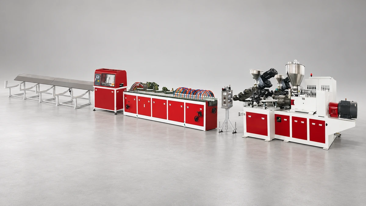
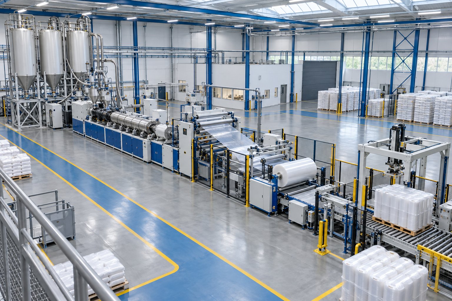
Imagine a factory floor where plastic pellets enter one end and a finished pipe, sheet, or window profile rolls off the other — all in one continuous motion. That entire sequence of machines working in concert is what the industry calls an extrusion line. It is not a single piece of equipment. It is an integrated production chain, and every station in it plays a role in the quality and consistency of the final product.
An extrusion line is a fully integrated manufacturing system that transforms raw thermoplastic pellets into continuous profiles, pipes, sheets, or films by feeding material through a hopper, melting it inside an extruder, shaping it through a die, and then calibrating, cooling, hauling off, and cutting or winding the finished product — all in a synchronized, uninterrupted workflow.
Defining the Extrusion Line as a Complete System
One of the most common misconceptions is treating the extruder as the entire system. In reality, the extruder is just one station among many. Here is how each major component contributes to the whole:
- Hopper and feeding system — delivers raw polymer pellets, regrind, or blended materials into the barrel at a controlled rate.
- Extruder (barrel and screw) — melts and homogenizes the polymer through a combination of shear energy and external heat.
- Die — shapes the molten polymer into the desired cross-section, whether round for pipe extrusion, flat for sheet, or complex for custom profiles.
- Calibration unit — locks in final dimensions using vacuum or pressure sizing immediately after the die exit.
- Cooling section — solidifies the shaped product through water baths, spray tanks, or air rings, depending on the application.
- Haul-off unit — pulls the product at a precise, constant speed to maintain dimensional accuracy and prevent distortion.
- Cutting, winding, or stacking station — converts the continuous output into usable lengths, coils, or stacked sheets ready for shipment.
You'll notice that every station must work in harmony. A perfectly functioning extruder paired with a poorly calibrated haul-off will still produce defective parts. The extrusion process is only as reliable as its weakest link, and that principle drives how engineers design, purchase, and maintain these systems.
When Extrusion Is the Right Manufacturing Process
Why choose extrusion over injection molding, blow molding, or thermoforming? The answer comes down to geometry, volume, and cost structure.
| Factor | Extrusion | Injection Molding | Blow Molding |
|---|---|---|---|
| Output type | Continuous lengths (pipes, profiles, films, sheets) | Discrete 3D parts | Hollow containers and bottles |
| Tooling cost | Lower — dies are simpler than molds | Higher — complex multi-cavity molds | Moderate — mold halves required |
| Best geometry | Constant cross-section over long runs | Complex 3D shapes with variable wall geometry | Hollow, enclosed shapes |
| Ideal production scale | High-volume continuous runs | Medium to high-volume batch runs | Medium to high-volume batch runs |
When you need to extrude pipe, produce kilometers of cable conduit, or roll out packaging film by the ton, extrusion delivers unmatched efficiency. The pvc extrusion process alone accounts for a massive share of global output in construction products like drainage pipe, siding, and window frames — a testament to how well-suited this method is for high-volume, constant-profile manufacturing. A chemical-resistant extrusion machine running fluoropolymers or specialty compounds can serve equally demanding niches in industrial and medical tubing.
Whether you are a newcomer trying to understand the fundamentals or an experienced operator looking for deeper technical insight, this article is designed as a vendor-neutral educational guide. Every section ahead unpacks a different layer of the system — from the physics inside the barrel to the financial math behind a smart purchasing decision.
How the Extrusion Process Works Step by Step
So what is extruding in practical terms? It is the act of forcing molten polymer through a shaped opening — but that single sentence barely scratches the surface. On the factory floor, the extrusion process is really a tightly choreographed relay where raw pellets pass through a series of stations, each one building on the work of the one before it. Break one link in that chain — a feed inconsistency, a temperature spike, a haul-off speed mismatch — and the defect ripples all the way to the finished product.
Feeding, Melting, and Metering Inside the Extruder
Everything starts at the hopper. Gravimetric feeders weigh material in real time to deliver a precise mass flow, while volumetric feeders rely on screw or auger speed to meter pellets by volume. Gravimetric systems cost more, but they compensate automatically for bulk-density variations in regrind or masterbatch blends — a detail that pays dividends in wall-thickness consistency downstream.
From the hopper throat, pellets drop into the barrel and meet the rotating screw. If you have ever wondered what is an extruder at its core, picture a precision-engineered screw turning inside a heated steel cylinder. As the screw rotates, it conveys the solid pellets forward. Friction between the pellets, the screw flights, and the barrel wall generates shear heat, which — combined with external band heaters along the barrel — gradually melts the polymer. By the time the material reaches the front of the screw, it should be a fully homogeneous melt delivered at a stable temperature, consistent viscosity, and controlled pressure. Achieving that uniformity is the central challenge of plasticization, and it depends heavily on screw geometry, barrel temperature profiling, and screw speed.
Die Shaping and Downstream Processing
The homogeneous melt exits the barrel and enters the die, which shapes it into the target cross-section — round for pipe, flat for sheet, annular for blown film, or complex for custom profiles. From this point forward, every piece of downstream extrusion equipment works together to lock in that shape before the polymer can sag, shrink, or distort.
Here is the full sequence, station by station:
- Die exit — the melt emerges in its desired profile geometry at elevated temperature.
- Calibration — vacuum sizing tanks or pressure calibration sleeves pull or push the soft extrudate against a precision tool to fix its outer dimensions. For pipe production, vacuum calibration cooling units are standard, applying negative pressure so the pipe expands against the calibration sleeve.
- Cooling — spray cooling tanks or water bath tanks remove residual heat. Water flow typically runs counter to the extrusion direction, creating a gentle temperature gradient that minimizes internal stress and prevents warping.
- Haul-off — caterpillar-track or belt pullers draw the product at a precise, steplessly adjustable speed. Wall thickness is directly regulated here: slower haul-off yields thicker walls, faster haul-off yields thinner walls.
- Cutting or winding — planetary saws, guillotine cutters, or chipless cutters slice rigid products to length, while winders coil flexible pipes or tubing into rolls. Winding speed synchronizes with extrusion speed and adjusts steplessly to prevent tension-related deformation.
- Stacking or packaging — finished lengths are collected on dump tables or automatically bundled for shipment.
The critical takeaway? Every station's speed and temperature must be synchronized. A haul-off running even slightly too fast will thin the product wall beyond tolerance; a cooling tank set too short will let residual heat soften the outer surface after sizing, causing deformation under the haul-off's clamping force. Experienced operators treat the entire system as one machine, not a collection of separate units. That mindset — thinking in terms of an integrated workflow rather than isolated components — is what separates a smooth-running production floor from one plagued by scrap and downtime.
Of course, the behavior of the whole system hinges on a variable that no amount of downstream tuning can fully compensate for: the design of the screw itself. Its geometry dictates melting efficiency, melt homogeneity, and output stability — topics that deserve a much closer look.
Single-Screw vs Twin-Screw vs Co-Extrusion Configurations Compared
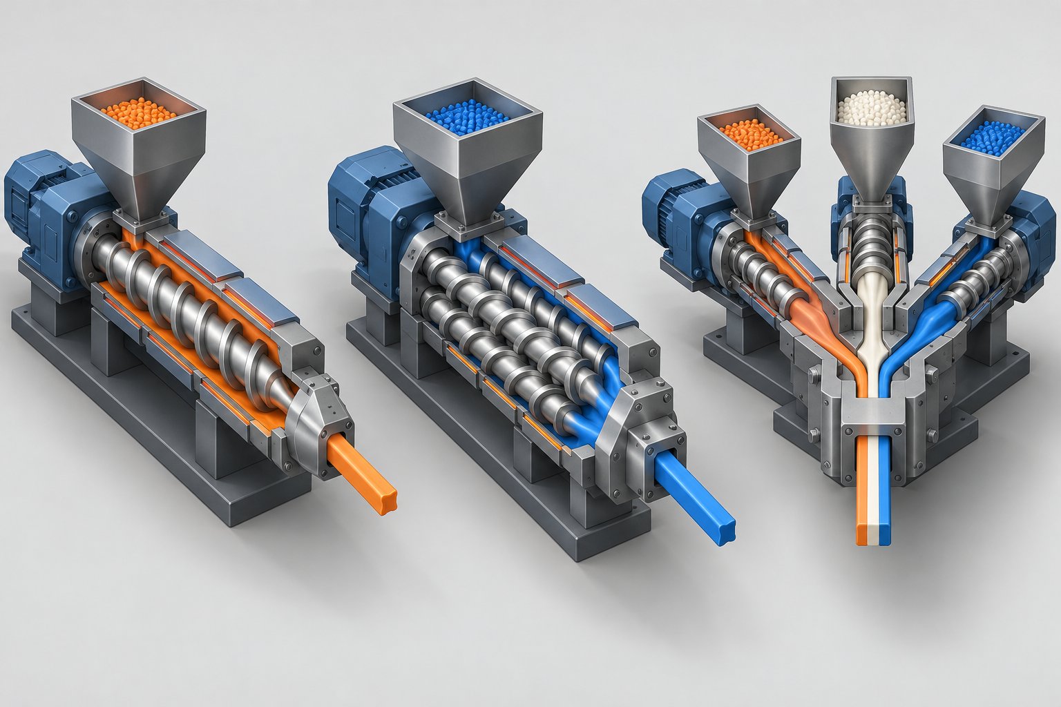
Screw geometry matters — but which type of screw arrangement belongs in your extrusion line in the first place? That choice shapes everything from capital outlay to the range of products you can manufacture. Three dominant configurations exist, and each one occupies a distinct niche. Surprisingly, no single resource has ever laid them side by side in a way that helps buyers and engineers make an informed decision. Let's change that.
Single-Screw Extruder Lines and Their Strengths
A single-screw setup is the workhorse of the plastics industry. One rotating screw inside a heated barrel melts and conveys polymer forward using friction and drag flow — a mechanically simple concept that translates into lower purchase price, straightforward operation, and easier maintenance. These lines dominate commodity applications: the extrusion of pipes in PVC and polyethylene, flat-die sheet production, blown-film packaging, and rigid window profiles all run overwhelmingly on single-screw platforms.
Typical length-to-diameter (L/D) ratios range from around 24:1 for basic processing up to 36:1 or more when additional melting, mixing, or degassing stages are needed. A longer barrel gives the polymer more residence time, which improves melt homogeneity but also increases floor-space requirements and energy input. For processors running a dedicated product — say, HDPE drainage pipe or PP sheet — the single-screw extrusion line delivers reliable throughput at a fraction of the cost of more complex alternatives.
Twin-Screw Extruder Lines for Compounding and Specialty Processing
When the job demands intensive mixing, precise thermal control, or the ability to handle difficult feedstocks, twin-screw configurations step in. Two intermeshing screws — either co-rotating (turning in the same direction) or counter-rotating (turning in opposite directions) — use positive displacement to push material forward mechanically, rather than relying on friction alone.
Co-rotating twin-screw extruders excel at high-shear compounding: blending glass fibers into engineering resins, dispersing color masterbatch, or performing reactive extrusion where chemical modification occurs inside the barrel. Their modular screw elements can be rearranged to create customized mixing, kneading, and venting zones. Counter-rotating designs, meanwhile, offer gentler processing and are widely used for rigid PVC profiles and pipes where minimizing thermal degradation is critical.
The trade-off? Twin-screw systems carry a higher capital cost and greater mechanical complexity — heavy-duty gearboxes, precision-machined intermeshing elements, and a steeper learning curve for operators. However, the superior venting capability makes them indispensable for processing hygroscopic or moisture-laden materials, and their mixing intensity often means fewer downstream quality issues, which can offset the initial investment over time.
Co-Extrusion Lines for Multi-Layer Products
Imagine feeding two, three, or even five different polymers through separate extruders into a single die — and producing one unified multi-layer product in a single pass. That is core extrusion logic behind co-extrusion lines, and it unlocks product performance that no mono-layer structure can match.
A co-extruded barrier film, for example, might sandwich an EVOH oxygen-barrier layer between structural polyethylene skins. A colored window profile can place an expensive UV-stabilized cap layer only where it is needed, while using lower-cost resin for the structural body. A foam-core sheet can combine a lightweight cellular center with smooth, solid skin layers for rigidity. Each polymer is melted in its own extruder, then the streams merge inside a feedblock or multi-manifold die to form one cohesive structure that exits as a single extrudate.
Whether you are shopping for a sheet extrusion machine capable of multi-layer output or evaluating a blown-film tower for food-packaging barrier films, co-extrusion adds material flexibility that single-layer lines simply cannot provide — at the cost of more extruders, more complex die tooling, and tighter process control requirements.
Configuration Comparison at a Glance
The table below consolidates the key differences. Whether you are evaluating a new extrusion line for sale or benchmarking your existing setup, this comparison offers a fast reference for matching configuration to application.
| Attribute | Single-Screw Line | Twin-Screw Line | Co-Extrusion Line |
|---|---|---|---|
| Design principle | One screw; friction/drag-flow conveyance | Two intermeshing screws; positive displacement | Multiple extruders (single or twin) feeding one die |
| Ideal materials | PE, PP, PVC, PS, PET — standard pellets | Filled compounds, powders, reactive blends, recycled flake | Any combination needing layered properties (PE/EVOH, PVC/ASA, PS/PE foam core) |
| Typical applications | Pipe, sheet, blown film, rigid profiles | Compounding, masterbatch, reactive extrusion, recycling | Barrier films, cap-layer profiles, foam-core sheets, multi-material tubing |
| Relative throughput | High for mono-material runs | Moderate to high; depends on formulation complexity | Varies — aggregate of individual extruder outputs |
| Maintenance complexity | Low — single screw and barrel set | Higher — precision gearbox, modular screw elements | Highest — multiple extruders plus multi-channel die |
| Relative capital cost | Lowest | 1.5 to 3 times higher than single-screw | Scales with number of extruders and die complexity |
Choosing the right configuration is the first strategic decision. But regardless of whether you run a single-screw, twin-screw, or co-extrusion setup, the performance of any line ultimately lives or dies inside the screw channel itself — in the feed zone, the compression zone, and the metering zone where raw pellets become a stable, pressure-ready melt.
Screw Design Fundamentals That Drive Line Performance
Every screw configuration discussed in the previous section — single, twin, co-extrusion — shares a common truth: the screw's internal geometry is the single biggest lever for melt quality, throughput stability, and energy efficiency. Yet most guides treat it as a footnote. In reality, the three functional zones inside the screw channel determine whether your extrusion plant delivers consistent product or fights a constant battle against surging, gels, and dimensional drift.
Feed Zone, Compression Zone, and Metering Zone Explained
Picture the screw as three workstations arranged end to end along its length. Each zone has a distinct job, and the geometry changes from one zone to the next to match that job precisely.
The feed zone sits directly beneath the hopper. Its channels are deep — intentionally so — to accept bulk pellets or powder and convey them forward through friction between the polymer, the screw flights, and the barrel wall. Channel depth here is at its maximum, and the helix angle is designed to maximize solid conveying without premature melting that could cause bridging at the feed throat.
As pellets travel into the compression (transition) zone, the channel depth gradually decreases. This shrinking volume compacts the solid bed, squeezes out trapped air, and generates the intense frictional shear heating that — combined with barrel heaters — drives the melting process. The compression ratio, defined as the ratio of feed-zone channel depth to metering-zone channel depth, is one of the most critical design parameters. A ratio too low leaves unmelted solids in the output; a ratio too high can overshear heat-sensitive polymers like PVC, causing degradation. For a typical pvc extrusion line, compression ratios are kept deliberately moderate — often between 2:1 and 2.5:1 — to manage thermal sensitivity.
Finally, the metering zone features a shallow, constant channel depth. Its purpose is straightforward yet essential: homogenize the melt and pump it toward the die at steady pressure. Think of it as the quality-control checkpoint of the screw. Melt temperature uniformity, pressure consistency, and viscosity stability are all refined here. When this zone is properly designed, the extrudate exits with minimal variation — exactly what downstream calibration and haul-off stations need to hold tight tolerances in an extrusion tube process.
Barrier Screws, Mixing Elements, and Specialty Designs
Standard three-zone screws handle a wide range of extruding tasks, but certain applications demand more. That is where specialty screw modifications enter the picture.
A barrier-flight screw adds a secondary flight within the transition zone. This extra flight creates two distinct channels — one carrying the solid bed and the other collecting the melt. As melting progresses, polymer flows over the barrier flight from the solids channel into the melt channel, preventing unmelted particles from reaching the metering zone. The result is faster, more uniform melting and fewer gels in the final product.
Beyond barrier flights, engineers specify mixing elements to address challenges that a smooth metering section cannot solve alone. Here are the most common modifications and when they are needed:
- Maddock (fluted) mixer — a dispersive element that forces melt through narrow slots, breaking up any remaining solid fragments or agglomerates. Ideal for polyolefin pipe and sheet lines where gel-free output is non-negotiable.
- Pineapple mixer — a distributive element with numerous pins or facets that fold and reorient the melt stream. Used for color masterbatch dispersion to eliminate streaking.
- Blister ring — creates a thin melt film that must pass over a raised land, generating high shear to break down agglomerates. Useful when processing recycled-content feedstock with inconsistent particle size.
- Variable-pitch flights — adjust conveyance rate along the screw length, allowing fine-tuning of residence time in each zone for heat-sensitive or high-output applications.
- Vented (two-stage) screw designs — incorporate a decompression zone followed by recompression, enabling moisture and volatiles to escape through a barrel vent port. Essential for recycling lines or hygroscopic resins processed without pre-drying.
Selecting the right combination of barrier geometry and mixing elements depends on the polymer, the additives, and the target product. A flat-die sheet line running virgin PP with color concentrate may need only a Maddock section, while a recycling operation extruding post-consumer HDPE flake might require barrier flights, a blister ring, and venting — all on the same screw.
Why Screw and Barrel Condition Matters More Than Most Operators Realize
Here is something experienced processors learn the hard way: even the best screw design delivers poor results when the hardware is worn. As the clearance between screw flight lands and the barrel bore increases due to abrasive or corrosive wear, backflow over the flights rises, conveying efficiency drops, and pressure fluctuations creep into the melt stream. Operators often blame temperature settings, resin lots, or die condition — when the real culprit is a worn screw-barrel assembly that no amount of parameter adjustment can compensate for.
If you are evaluating a plastic extruder for sale on the used market, screw and barrel wear should be the first inspection priority. And if your existing line shows declining output at constant screw speed, rising melt temperatures you did not set, or increasing gel counts, the screw-barrel interface deserves immediate attention. For extrusion plants, recycling operations, and processing teams dealing with output instability, melt-quality problems, pressure fluctuation, or overheating, NANHAIYA provides specialist screw barrel support designed to diagnose and resolve exactly these kinds of performance issues — a practical starting point when troubleshooting points to wear or design mismatch.
Screw geometry and screw condition set the ceiling for what any extrusion line can achieve. But even a perfectly tuned screw-barrel assembly cannot overcome a fundamental mismatch between the line configuration and the end product it is asked to produce — a topic that calls for a clear, application-by-application mapping of which line type fits which job.
Types of Extrusion Lines by Application and End Product
Matching the right extrusion machine to the right end product sounds obvious — until you realize how many variables separate a PVC drain-pipe setup from a medical tubing extrusion line or a multi-layer blown-film tower. Each product category demands its own downstream equipment, its own process tolerances, and its own material handling logic. Here is the practical mapping that ties it all together.
Pipe and Tubing Extrusion Lines
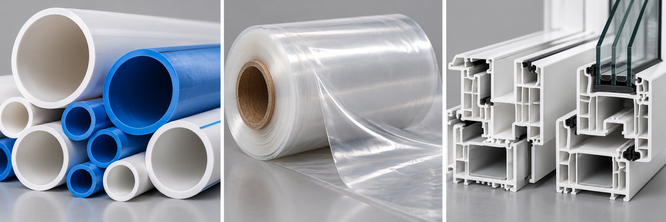
Pipe lines are among the most recognizable setups in the plastic extrusion process. A single-screw extruder feeds molten polymer — typically PVC, PE, or PPR — through an annular die, and the soft tube immediately enters a vacuum sizing tank that pulls the outer wall against a precision sleeve. Downstream, spray cooling tanks solidify the pipe over several meters, a caterpillar haul-off draws it forward at controlled speed, and a planetary cutter rotates around the circumference to make clean, chip-free cuts to length. For large-diameter HDPE water and gas mains, a plastic pipe extrusion machine may include coiling stations capable of winding pipes up to 160 mm onto drums for continuous-length delivery.
Tubing lines share the same core principle but operate at a smaller scale with far tighter tolerances. Medical-grade and industrial tubing extrusion often adds vacuum cooling tanks and laser micrometers that feed wall-thickness data back to the puller in real time, enabling sub-millimeter dimensional control. If you are browsing a pipe extruder machine sale listing, pay special attention to whether the downstream equipment can support the tolerance band your application actually requires — a commodity drain-pipe line will not meet medical specs without significant upgrades.
Sheet and Film Extrusion Lines
Flat-die sheet lines push melt through a wide slot die onto a polishing calender stack — a series of temperature-controlled chrome rollers that smooth, gauge, and cool the sheet simultaneously. The finished sheet then travels through additional cooling rolls, edge trimmers, and a cross-cutter or winder. These lines excel at producing thermoforming stock in materials like PET, PP, and PS, where surface finish and uniform thickness directly affect downstream forming quality.
Blown-film lines take a different approach entirely. An annular die extrudes a thin melt tube upward while an air ring inflates and cools it into a bubble. Collapsing frames flatten the bubble, nip rolls seal it, and winders collect the finished film. Blown film dominates flexible packaging because the biaxial orientation created during inflation improves strength and barrier properties — advantages flat-die sheet cannot replicate for thin-gauge applications.
Profile Extrusion Lines
Window frames, composite decking, cable trunking, and custom architectural shapes all emerge from profile lines. The defining feature here is the calibration tooling — complex vacuum calibrators that must match the die's cross-section exactly to hold tight dimensional tolerances on intricate geometries. Haul-off alignment is equally critical; even a slight angular misalignment between the puller and the calibrator introduces twist or bow into the finished profile. Most profile lines also include flying-saw cutters synchronized to line speed for precise cut-to-length output.
Line-Type Comparison by Application
The table below maps each major category to its defining characteristics, giving you a quick-reference guide when specifying or evaluating a system.
| Line Type | Typical Materials | Key Downstream Equipment | Common End Products | Critical Process Parameters |
|---|---|---|---|---|
| Pipe | PVC, PE, PPR, HDPE | Vacuum sizing tank, spray cooling, planetary cutter, coiler | Drainage pipe, water/gas mains, conduit | Vacuum level, cooling length, haul-off speed, ovality control |
| Tubing | PVC, PE, PA, TPU, silicone | Vacuum cooling tank, laser micrometer, precision puller, rotary cutter | Medical tubing, industrial hose, fuel lines | Wall-thickness tolerance, concentricity, OD/ID ratio |
| Flat-die sheet | PET, PP, PS, ABS, PC | Polishing calender stack, edge trimmer, cross-cutter or winder | Thermoforming stock, signage, construction panels | Calender roll temperature, gap setting, sheet flatness |
| Blown film | LDPE, LLDPE, HDPE, PA, EVOH | Air ring, collapsing frame, nip rolls, winder | Packaging film, stretch wrap, agricultural film | Blow-up ratio, frost-line height, air-ring cooling rate |
| Profile | PVC, WPC, ABS, ASA | Vacuum calibrator, spray/immersion cooling, belt haul-off, flying saw | Window frames, decking, cable trunking, trim | Calibrator vacuum, haul-off alignment, cooling uniformity |
Choosing the correct line type is essential, but the system will only perform to its potential if the material fed into it is properly prepared. Moisture content, additive dosing, and regrind ratios all influence melt behavior long before the polymer ever reaches the screw — factors that deserve their own focused discussion.
Material Preparation and Polymer Selection for Extrusion Success
A perfectly engineered screw, a flawlessly calibrated die, and a state-of-the-art downstream section will still produce defective product if the material entering the hopper is not properly prepared. Material preparation is the overlooked gatekeeper of extrusion quality — and it is responsible for a surprising number of problems that operators mistakenly blame on the extruder itself. Moisture in a hygroscopic resin, an inaccurate masterbatch dose, or an inconsistent regrind blend can trigger splay marks, dimensional instability, and mechanical failures that no amount of downstream tuning can fix.
Drying, Blending, and Additive Incorporation
Not every polymer needs drying, but get this step wrong with one that does, and the consequences are immediate. Hygroscopic resins — PET, nylon (PA), polycarbonate (PC), and ABS — absorb atmospheric moisture that, if not removed before processing, causes hydrolytic degradation inside the barrel. The water molecules actually break polymer chains apart at melt temperatures, reducing molecular weight and destroying mechanical properties. On the surface, you will see splay marks (silver streaks), bubbles, and a rough finish. Inside, the part has lost strength it will never recover.
Each resin has a target moisture ceiling. PET, for example, typically needs to be dried below 50 ppm (0.005%) moisture content using a desiccant dryer, while nylon often requires levels below 0.1-0.2% depending on the grade. Skipping this step — or using an undersized dryer that cannot maintain dew-point performance under production load — is one of the fastest ways to generate scrap on an extrusion production line.
Beyond drying, consistent blending is equally critical. Gravimetric blending systems weigh each ingredient — virgin resin, regrind, color masterbatch, UV stabilizers, processing aids — in real time using precision load cells. Unlike volumetric feeders that estimate by volume or timing, gravimetric blenders compensate automatically for bulk-density differences between materials. When you are mixing low-density regrind flake with dense virgin pellets, that compensation is the difference between a stable recipe and a color-streaked, dimensionally inconsistent product.
Regrind incorporation deserves special attention. Reintroducing production scrap back into the feed stream is standard practice across pipe extrusion line operations and sheet extrusion alike, but the ratio must stay within limits that preserve mechanical properties and surface quality. Industry norms vary by application and resin type, and exceeding them degrades impact strength, increases melt-flow variability, and introduces contamination risk — especially if regrind particle size is not uniform. A well-maintained granulator producing consistent flake, paired with a gravimetric blender holding tight ratio control, keeps regrind from becoming a liability.
Matching Polymers to the Right Line Configuration
What is extrusion if not a negotiation between the polymer's behavior and the machine's capability? Every resin brings its own thermal sensitivity, viscosity curve, and additive package — and those characteristics dictate which screw type, barrel metallurgy, and downstream setup will deliver reliable results. Feeding the wrong polymer through the wrong configuration is like running diesel in a gasoline engine: you might get output, but you will pay for it in quality, wear, and downtime.
Here is a practical polymer-to-line guide covering the materials most commonly processed on plastic extrusion machines:
- PE (Polyethylene — HDPE, LDPE, LLDPE) — runs well on standard single-screw extruders with moderate compression ratios (3:1 to 3.5:1). Barrier screws with a Maddock mixer improve melt homogeneity for pipe and film. No special barrel metallurgy required for virgin material, though glass-filled PE grades benefit from bimetallic barrel liners to resist abrasive wear.
- PP (Polypropylene) — similar processing to PE on single-screw setups. Controlled cooling downstream is important to minimize warping and crystallization-related shrinkage in thick-wall products. A sheet extruder machine running PP for thermoforming stock benefits from a polishing calender stack with precise temperature zoning.
- PVC (Polyvinyl Chloride) — the most thermally sensitive commodity resin. Twin-screw extruders, particularly counter-rotating conical designs, are strongly preferred because they offer gentle shear and positive conveying that prevents localized overheating. Barrel and screw materials must resist the corrosive hydrochloric acid released when PVC degrades — corrosion-resistant alloys and specialized coatings are standard. Processing PVC on a line designed for polyolefins invites degradation, black specks, and accelerated equipment wear.
- PET (Polyethylene Terephthalate) — mandatory desiccant drying to extremely low moisture levels before processing. Typically run on single-screw extruders with barrier screws and vacuum venting to remove residual moisture and acetaldehyde. Intrinsic viscosity (IV) must be monitored, as any degradation lowers it irreversibly.
- ABS (Acrylonitrile Butadiene Styrene) — hygroscopic, so thorough drying is required. Processes well on single-screw extruders with general-purpose or barrier screw designs. Moderate shear sensitivity means temperature profiles should be carefully managed to prevent yellowing or surface defects.
- PA (Nylon / Polyamide) — highly hygroscopic with a narrow processing window. Requires aggressive pre-drying and often benefits from vented extruder barrels. Glass-filled PA grades are extremely abrasive, demanding bimetallic barrels and hardened screws — standard nitrided steel will wear rapidly. Twin-screw setups are common when compounding PA with high filler loads.
A recurring pattern emerges across all these polymers: material preparation failures — insufficient drying, inaccurate blending, contaminated regrind, or mismatched barrel metallurgy — are the root cause of many downstream quality problems that operators misattribute to the extruder, the die, or the cooling section. Diagnosing an extrusion defect should always start at the feedstock, not the die exit.
Getting the material right is foundational. But even with perfectly prepared feedstock and a well-matched line configuration, the system still needs a brain — and that brain is the automation and control architecture that coordinates every station from hopper to cutter in real time.
Automation and Smart Controls on Modern Extrusion Lines
Material science and screw geometry set the physical limits of your process. But what actually keeps every station running in lockstep — adjusting barrel temperatures, compensating for viscosity shifts, and catching a pressure spike before it becomes a die blowout? The answer is the control system. And yet, despite being the central nervous system of every modern extrusion line, automation is the topic most guides simply ignore. That gap matters because, for today's buyers and operators, the control architecture often determines whether a line delivers consistent product around the clock or demands constant babysitting.
PLCs, HMIs, and Closed-Loop Control
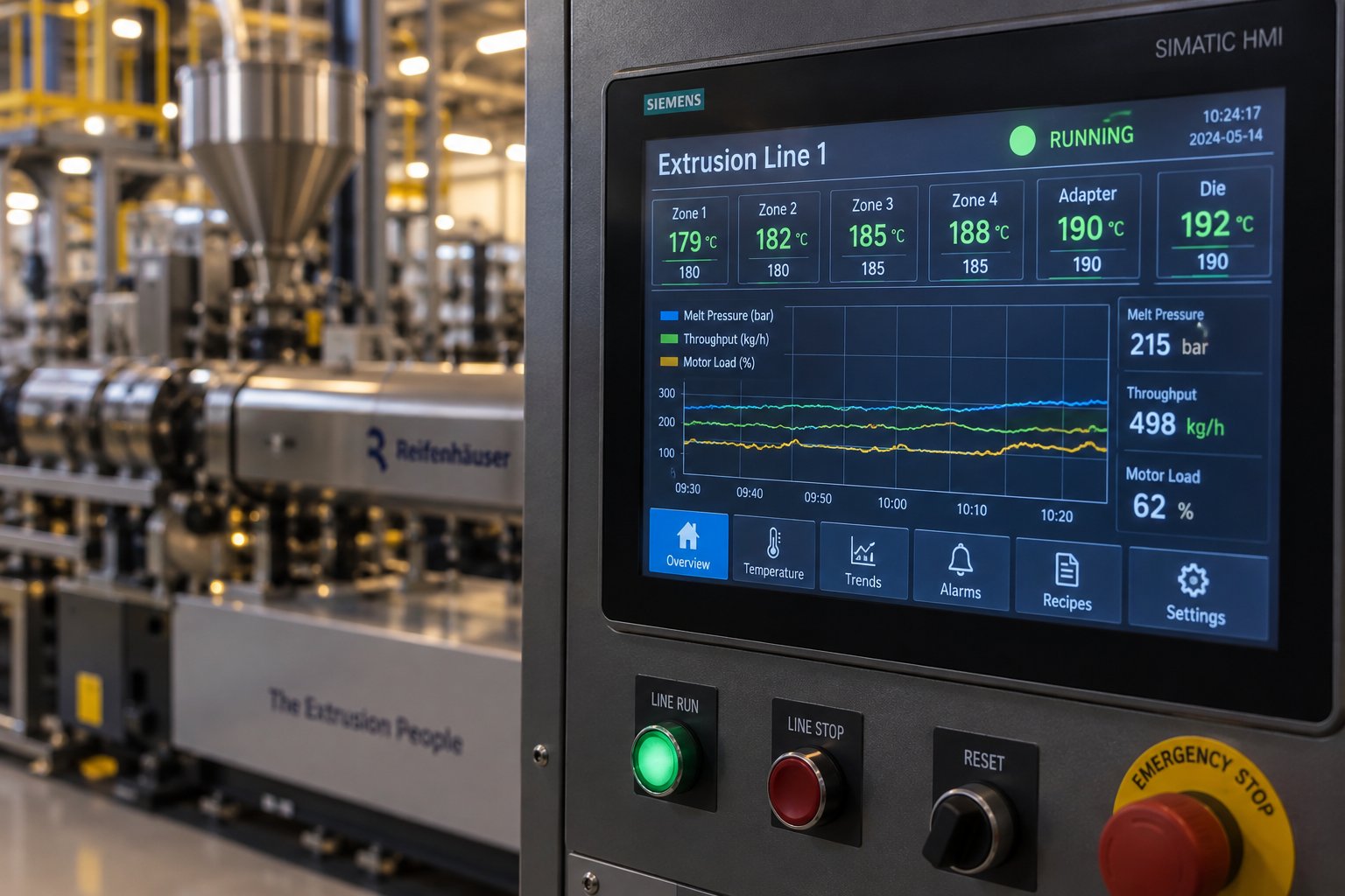
At the heart of the system sits a programmable logic controller (PLC). If you have ever wondered what are extruders in a modern factory context, think of them not as standalone machines but as sensor-rich platforms coordinated by a PLC that manages dozens of variables simultaneously. Each barrel zone runs its own PID control loop — comparing a thermocouple reading against the setpoint and modulating heater output and cooling in a split-range configuration so the two never fight each other. Screw speed flows through a variable frequency drive (VFD) that the PLC references, while the haul-off, cutter, and winder all receive their speed commands as ratios of a single master speed value. Change the master, and every downstream station updates proportionally — keeping the draw ratio constant and wall thickness on target.
Operators interact with this web of logic through a human-machine interface (HMI) — a touchscreen panel or PC-based dashboard displaying real-time melt pressure, motor load, throughput, zone temperatures, and alarm status. A well-designed HMI does more than display numbers; it trends them, so an operator can spot a gradually climbing die pressure (suggesting screen-pack fouling) long before it triggers an alarm.
The real payoff, however, comes from closed-loop feedback. Consider a tubing extruder producing precision medical-grade product. An ultrasonic wall-thickness gauge downstream measures the extrudate continuously and feeds that data back to the PLC, which trims the haul-off speed ratio automatically — thickening or thinning the wall in real time without any operator intervention. Gravimetric throughput control works on a similar principle: a loss-in-weight feeder reports actual mass flow, and the PLC adjusts screw speed to hold a constant output rate even as bulk density in the hopper changes. These closed-loop systems transform an extrusion line from a manually tuned process into a self-correcting one.
Industry 4.0 Integration and Data-Driven Optimization
Closed-loop control keeps the process stable minute to minute. But what about shift to shift, week to week, or across multiple production lines in different plants? That is where Industry 4.0 connectivity enters the picture.
Modern systems connect the PLC layer upward to MES (Manufacturing Execution Systems) and ERP (Enterprise Resource Planning) platforms. This integration enables automatic OEE tracking — measuring availability, performance, and quality in real time rather than reconstructing them from paper logs days later. Predictive maintenance algorithms analyze time-series data from vibration sensors, motor-current signatures, and melt-pressure trends to flag developing problems — a bearing starting to fail in the gearbox, a heater band degrading — before they cause unplanned downtime. Recipe management systems store every product-specific setpoint, PID gain, and speed ratio, enabling faster changeovers with repeatable results.
Edge computing adds another layer. Instead of streaming all sensor data to a remote cloud for analysis, edge devices process it locally at the machine, delivering real-time statistical process control (SPC) charts and anomaly detection with near-zero latency. Historical data analysis on these platforms reveals long-term process drift — perhaps a gradual increase in specific energy consumption that signals screw wear — enabling continuous improvement cycles grounded in evidence rather than guesswork.
Here are the key automation components and their functions on a well-equipped line:
- PLC with multi-zone PID — independently controls each barrel and die temperature zone with split heat/cool outputs.
- VFD or servo drive — regulates extruder screw speed and responds to pressure-trim commands from the PLC.
- HMI touchscreen — provides real-time visualization of all process variables, trend graphs, and alarm management.
- Melt-pressure transducer — delivers safety-critical feedback and process diagnostics; hardwired high-pressure interlock protects tooling.
- Inline gauging (laser, ultrasonic, or beta gauge) — measures product dimensions for closed-loop thickness or diameter control.
- Gravimetric feeder — maintains constant mass throughput regardless of bulk-density variation in the feedstock.
- MES/ERP gateway — connects machine-level data to plant-wide OEE dashboards, scheduling, and quality systems.
- Edge computing node — runs real-time SPC, predictive maintenance models, and anomaly detection locally at the line.
- Recipe management module — stores and recalls product-specific parameters for fast, repeatable changeovers.
The ROI from automation extends well beyond labor savings. Reduced scrap from closed-loop gauge control, faster changeovers from stored recipes, consistent quality from real-time SPC, and avoided downtime from predictive alerts — together, these benefits compound. When evaluating used extrusion lines, the control system vintage and capability deserve as much scrutiny as the mechanical condition of the screw and barrel. A mechanically sound line with an outdated relay-based control panel will cost you in scrap and operator hours what it saved you on the purchase price.
Automation keeps the process on target. But what happens when something still goes wrong — when output surges, pressure spikes, or black specks suddenly appear in the extrudate? Diagnosing those problems quickly, rather than chasing symptoms, is a skill that separates experienced operators from frustrated ones.
Troubleshooting Common Extrusion Line Problems
Your automation dashboards are green, your recipe is loaded, your material is dried — and yet the extrudate coming off the die looks wrong. Maybe the wall thickness is drifting. Maybe you are seeing gels, black specks, or a rough surface that was not there yesterday. Sounds familiar? Every operator faces these moments, and the difference between an hour of downtime and a full shift of scrap usually comes down to how systematically you diagnose the root cause.
Diagnosing Output Instability and Melt-Quality Defects
Output instability rarely has a single origin. It is the product of interactions between material behavior, thermal conditions, and mechanical wear — which is exactly why random parameter changes tend to make things worse. Here is how to read the most common symptoms and trace them back to their source.
Surging — a cyclic variation in output rate — is one of the most frustrating problems on any extruder line. You will see it as rhythmic changes in wall thickness, periodic diameter shifts on pipe, or pulsating film gauge. The cycle time often holds a clue. Short-period surges (a few seconds) frequently point to inconsistent feeding — a bridging hopper, a starving feeder, or bulk-density variations in the feedstock. Longer-period surges can indicate a solid-bed breakup pattern inside the screw's transition zone, where chunks of unmelted polymer intermittently release and surge forward. Worn screw flights amplify the problem by reducing conveying efficiency and allowing backflow over the flight lands.
Melt fracture appears as spiral distortions or a rough "orange peel" texture on the extrudate surface. It happens when wall shear stress at the die exit exceeds the polymer's critical threshold. Reducing extrusion speed, raising die temperature, or switching to a die with a longer land length can bring shear stress back into an acceptable range.
Gels and unmelted particles show up as small, clear or translucent lumps embedded in an otherwise smooth product. They signal incomplete melting — often from a screw that lacks sufficient compression ratio or mixing capability for the resin being processed. Barrier screws with dispersive mixing elements, such as a Maddock section, are specifically designed to eliminate this defect.
Black specks are degraded polymer fragments that have been trapped in stagnant zones inside the barrel, die, or adapter — sometimes for hours or even days — before breaking loose into the melt stream. Thorough purging between material changes, proper shutdown procedures, and streamlined flow-channel designs reduce their occurrence. Persistent black specks can also indicate barrel liner damage that creates dead spots where material hangs up and carbonizes.
Uneven wall thickness is common on pipe and profile extrusion line setups. When the variation follows a consistent pattern around the circumference, a misaligned die or off-center mandrel is the likely culprit. Random variation, on the other hand, usually traces back to melt-temperature non-uniformity, pressure fluctuations from screw wear, or inconsistent cooling downstream.
Resolving Pressure Fluctuation, Overheating, and Blockages
Melt pressure is one of the most revealing diagnostics on a plastic extrusion machine. Steady pressure means stable flow; anything else is a signal worth investigating.
Pressure spikes — sudden upward jumps — often indicate a screen pack that is gradually blinding with contaminants or degraded material. As the open area of the screen shrinks, the extruder must push harder to maintain flow. If left unchecked, pressure can climb to the safety-interlock threshold and shut the line down. The fix is straightforward: replace the screen pack and inspect for upstream contamination sources. A partially blocked breaker plate produces similar symptoms.
Low or declining pressure tells a different story. When pressure drops at constant screw speed, the screw is losing its ability to convey and pressurize melt efficiently. Worn flight tips and an enlarged barrel bore allow polymer to leak backward over the flights instead of being pushed forward — a classic wear signature. Feed-throat bridging, where material clogs the entry point into the barrel, also starves the screw and collapses head pressure.
Overheating may come from excessive shear — a screw spinning too fast for the resin's viscosity — or from failed cooling circuits that can no longer extract heat from the barrel zones. Thermocouple drift is a subtler but equally damaging cause: if a sensor reads low, the control system pumps in extra heat the barrel does not need. Verifying sensor accuracy with a handheld pyrometer or calibration check should be part of routine maintenance on any extrude line.
Die blockages typically result from degraded material buildup, foreign contaminants, or a resin that has partially cross-linked inside the flow channel. Downstream blockages — in calibration sleeves or cooling tanks — usually stem from material buildup or a process upset that allowed the extrudate to deform and jam against the tooling.
Quick-Reference Troubleshooting Table
The table below maps the most common symptoms to their likely causes and practical corrective actions, giving you a rapid diagnostic framework you can reference directly on the production floor.
| Symptom | Likely Causes | Recommended Corrective Actions |
|---|---|---|
| Output surging (cyclic thickness variation) | Feed-throat bridging; inconsistent feeder output; solid-bed breakup; worn screw flights | Check hopper flow; calibrate feeder; inspect screw for wear; consider barrier screw upgrade |
| Melt fracture / rough surface | Excessive die shear stress; low die temperature; short die land length | Reduce line speed; raise die temperature; switch to a die with longer land |
| Gels or unmelted particles | Insufficient compression ratio; lack of mixing elements; low barrel temperature | Add dispersive mixer (Maddock); increase transition-zone temperature; verify screw design matches resin |
| Black specks | Degraded material in dead zones; barrel liner damage; inadequate purging | Purge thoroughly between runs; inspect barrel for scoring or damage; streamline adapter flow path |
| Uneven wall thickness | Misaligned die/mandrel; melt-temperature non-uniformity; screw wear; inconsistent cooling | Re-center die tooling; check barrel zone temperatures; measure screw/barrel clearances; balance cooling flow |
| Pressure spikes | Blinded screen pack; blocked breaker plate; contaminated feedstock | Replace screen pack; clean breaker plate; audit incoming material for contamination |
| Low or declining pressure | Screw/barrel wear; feed-throat bridging; hopper empty or bridged | Measure flight-to-barrel clearance; clear feed throat; inspect hopper and feeder |
| Overheating beyond setpoint | Excessive screw speed (shear heat); failed barrel cooling circuit; drifted thermocouple | Reduce screw RPM; inspect cooling water flow and valves; calibrate temperature sensors |
| Die or downstream blockage | Material degradation buildup; foreign contamination; cross-linked resin; process upset causing extrudate deformation | Disassemble and clean die; check upstream for contamination; review shutdown and purge procedures |
The Common Thread: Screw and Barrel Condition
Scan the "Likely Causes" column above and you will notice a pattern — worn screw flights, damaged barrel liners, and mismatched screw geometry appear repeatedly. That is not coincidence. The screw-barrel assembly is the component most directly responsible for conveying consistency, melt homogeneity, and pressure stability. When clearances open up due to abrasive or corrosive wear, every other station in the line inherits the instability. Operators compensate by raising temperatures, slowing speed, or tightening downstream controls, but those workarounds only mask the underlying decay until it becomes impossible to ignore.
If your troubleshooting consistently points back to the screw and barrel — declining output at constant RPM, rising melt temperature you did not program, pressure swings that no PID tuning can calm — it is time to assess the hardware itself. Whether you are running a high-volume pipe setup, a tight-tolerance profile extrusion line, or even evaluating a used extruder for sale where wear history is uncertain, NANHAIYA offers specialist screw barrel support for extrusion plants, recycling operations, and processing teams dealing with output instability, melt-quality problems, pressure fluctuation, overheating, and blockages. When diagnosis narrows to wear or design mismatch, having a dedicated screw-barrel partner eliminates the guesswork.
Solving problems on the production floor protects today's output. But the longer-term question — whether the line itself was the right investment, and how to evaluate the next one — requires a different kind of analysis: one grounded in capital costs, total cost of ownership, and the financial math behind genuine ROI.
Cost Considerations and ROI for Extrusion Line Investments
Every decision discussed so far — screw geometry, line configuration, automation level, material preparation — eventually lands on a single question: what will it cost, and will the investment pay for itself? Surprisingly, most technical guides stop right before answering it. That leaves buyers navigating six- and seven-figure capital decisions with incomplete information. Whether you are specifying your first system or replacing an aging pipe extruder with a modern platform, a clear financial framework turns a gut-feel purchase into a defensible business case.
Capital Cost Factors and What Drives Pricing
No two extrusion lines carry the same price tag, and the spread is enormous. What is a plastic extruder going to cost you? That depends on a handful of variables that interact in ways worth understanding before you request a single quote.
Extruder size (screw diameter) is the most obvious driver. A 45 mm laboratory-scale single-screw unit occupies a different cost universe than a 120 mm production machine. Larger screws require heavier barrels, bigger drive motors, and beefier gearboxes — all of which scale cost upward. According to industry pricing data, entry-level single-screw extruders suitable for basic applications can start around $30,000 to $80,000, while mid-range commercial models fall between $80,000 and $200,000, and fully industrial single-screw systems can reach $500,000 or more. Twin-screw systems command substantially higher prices — production-scale co-rotating units commonly range from $300,000 to $800,000, with high-performance compounding lines exceeding $1,500,000.
Line configuration multiplies that base cost. A simple mono-layer setup costs far less than a co-extrusion arrangement requiring two or three additional extruders and a multi-manifold die. A pvc sheet extrusion line with a polishing calender stack, edge trimmers, and automated stacking adds downstream complexity — and cost — that a basic rod or profile setup does not.
Several other factors layer on top:
- Downstream complexity — vacuum sizing tanks, multi-stage cooling baths, laser gauging, and automated cutters all add to the total investment. The more stations, the higher the price.
- Automation level — a line with PLC-based closed-loop control, HMI dashboards, gravimetric feeding, and MES connectivity will cost more upfront than a manually operated setup — but the payback often justifies it, as the previous chapter on automation illustrated.
- Material of construction — standard nitrided screws and barrels suit many polyolefin applications. Processing abrasive glass-filled compounds or corrosive PVC, however, demands bimetallic barrel liners and hardened or coated screws, adding a meaningful premium to the extrusion machines you are quoting.
- Brand and origin — European-built lines generally carry the highest price points, followed by established Asian manufacturers, with economy-tier equipment occupying the entry level. Price differences reflect not just labor costs but also engineering depth, component quality, and after-sales support infrastructure.
Resist the temptation to compare lines on purchase price alone. A lower-cost system that generates higher scrap, consumes more energy, or requires frequent wear-part replacements can easily cost more over its productive life — which is exactly why total cost of ownership deserves equal attention.
Total Cost of Ownership and ROI Considerations
The purchase price is just the admission ticket. The real financial story unfolds over the next ten to fifteen years of operation. Total Cost of Ownership (TCO) captures every direct and indirect expense across an asset's lifetime, giving a far more accurate picture of what the line actually costs to run.
Here are the key TCO components every buyer should model before signing a purchase order:
- Energy consumption — typically the largest ongoing expense. Specific energy consumption for single-screw systems generally falls between 0.15 and 0.25 kWh per kilogram of output, while well-configured twin-screw lines can achieve 0.12 to 0.22 kWh/kg for mixing-intensive applications. At 5,000 operating hours annually, even a small efficiency difference compounds into tens of thousands of dollars per year.
- Tooling and spare parts — dies, screen packs, screw elements (for twin-screw systems), barrel liners, and calibration sleeves all wear and require periodic replacement. Screw replacement on a single-screw line might cost $3,000 to $15,000; a full set of twin-screw elements can run $20,000 to $100,000.
- Maintenance labor — simpler single-screw lines often allow in-house maintenance, while twin-screw gearbox overhauls may require specialized technicians. Annual routine maintenance costs range from roughly $3,000 to $15,000 for single-screw setups and $20,000 to $35,000 for twin-screw systems.
- Scrap and rework rates — a line producing 5% scrap on 5,000 metric tons per year at $2/kg wastes $500,000 annually. Cutting that rate by even two percentage points through better screw-barrel assemblies and closed-loop gauge control recovers $200,000 every year — a return that dwarfs the cost of the upgrade.
- Unplanned downtime — every hour the line sits idle is lost revenue. If your extruders for sale evaluation includes used equipment, factor in the downtime risk from worn components that may fail unexpectedly. Predictive maintenance and quality wear parts reduce this risk significantly.
- Disposal and decommissioning — retiring outdated equipment incurs removal costs and potential environmental compliance expenses, especially for lines that processed PVC or other chemically aggressive materials.
Imagine two scenarios. In the first, you choose a lower-cost system with standard-grade screws and minimal automation. In the second, you invest more upfront in bimetallic barrels, hardened screws, and closed-loop control. The first system might save $100,000 at purchase — but if it runs at 2% higher scrap, consumes 10% more energy, and needs a full screw-barrel replacement two years sooner, those savings evaporate well before the five-year mark. Investing in quality screw-barrel assemblies and automation reduces total cost of ownership despite the higher initial spend, a pattern confirmed repeatedly across the industry.
Used extrusion lines can offer genuine value — especially for processors entering a new product category or scaling capacity on a budget. However, they require careful inspection of wear components. Flight-to-barrel clearance on the screw, barrel bore diameter, gearbox condition, and control-system vintage should all be measured and documented before purchase. A used line with a worn-out screw and an obsolete relay panel is not a bargain — it is a renovation project with an unpredictable budget.
The ROI formula itself is straightforward: net profit generated by the investment divided by total investment cost, expressed as a percentage. But the inputs that feed it — energy savings, scrap reduction, throughput gains, reduced downtime — depend entirely on how well the line is specified for the actual job it needs to do. Overbuying capability you will never use wastes capital. Underbuying forces compromises in quality, speed, or material flexibility that erode margins for the life of the equipment.
Informed specification — matching line capability to actual production needs, polymer requirements, and growth projections — is the single best way to maximize ROI. Every chapter in this guide, from screw geometry to automation architecture, feeds into that specification process. The manufacturers who get the best returns are the ones who treat equipment selection not as a purchasing exercise but as an engineering decision grounded in process knowledge, material science, and honest financial modeling.
Frequently Asked Questions About Extrusion Lines
1. What is the difference between an extruder and an extrusion line?
An extruder is a single machine — a barrel and screw assembly — that melts and conveys polymer. An extrusion line, by contrast, is the entire integrated production system: hopper, extruder, die, calibration unit, cooling section, haul-off, and cutting or winding station all working in synchronized concert. Thinking of the extruder as the whole system is one of the most common misconceptions in plastics manufacturing. Every downstream station contributes to final product quality, and a line is only as reliable as its weakest link.
2. How do I choose between a single-screw and twin-screw extrusion line?
Single-screw lines are ideal for commodity applications such as pipe, sheet, film, and profiles made from standard pelletized resins like PE, PP, and PVC. They cost less, are simpler to maintain, and deliver high throughput on dedicated runs. Twin-screw lines are the better choice when intensive mixing, compounding, reactive extrusion, or processing of difficult feedstocks (recycled flake, highly filled compounds, heat-sensitive materials) is required. Co-rotating twin-screw designs offer superior mixing and venting, while counter-rotating types provide gentler conveying suited to rigid PVC. The decision ultimately depends on your material, product complexity, and budget.
3. What causes output surging on an extrusion line and how can it be fixed?
Output surging — cyclic variation in wall thickness or diameter — typically stems from inconsistent feeding (hopper bridging, feeder calibration issues), solid-bed breakup inside the screw's transition zone, or worn screw flights that allow backflow over the flight lands. Short-period surges often point to feed problems, while longer-period cycles suggest internal melting instability. Corrective steps include inspecting hopper flow, recalibrating the feeder, measuring screw-to-barrel clearance for wear, and considering a barrier-screw upgrade. Specialists like NANHAIYA (nhyscrews.com) can provide screw barrel assessments when wear is suspected.
4. Why is material drying important before extrusion?
Hygroscopic polymers such as PET, nylon, polycarbonate, and ABS absorb moisture from the air. If that moisture is not removed via desiccant drying before processing, water molecules break polymer chains apart at melt temperatures — a process called hydrolytic degradation. The visible results include splay marks (silver streaks), bubbles, and rough surfaces, while internally the part loses strength permanently. Each resin has a specific moisture ceiling; PET, for instance, must typically be dried below 50 ppm. Skipping or under-sizing the drying step is one of the fastest ways to generate scrap on any extrusion production line.
5. What factors determine the total cost of owning an extrusion line?
Purchase price is only the starting point. Total Cost of Ownership (TCO) includes energy consumption (often the largest ongoing expense), tooling and spare parts (screws, barrels, dies, screen packs), maintenance labor, scrap and rework rates, unplanned downtime losses, and eventual decommissioning costs. A lower-priced line that generates higher scrap, consumes more energy, or needs premature screw-barrel replacement can easily cost more over its 10-to-15-year service life than a higher-quality system. Investing in bimetallic barrels, hardened screws, and closed-loop automation typically reduces TCO despite the higher upfront spend.
Written by
Nanhaiya Technical Team
Zhoushan Nanhaiya Plastic Machinery Co., Ltd.
The Nanhaiya technical team supports screw and barrel manufacturing projects through application review, technical communication, custom manufacturing coordination, and production and quality control.
Discuss Your Application
Related Articles
More insights on screw barrel technology and plastics processing.
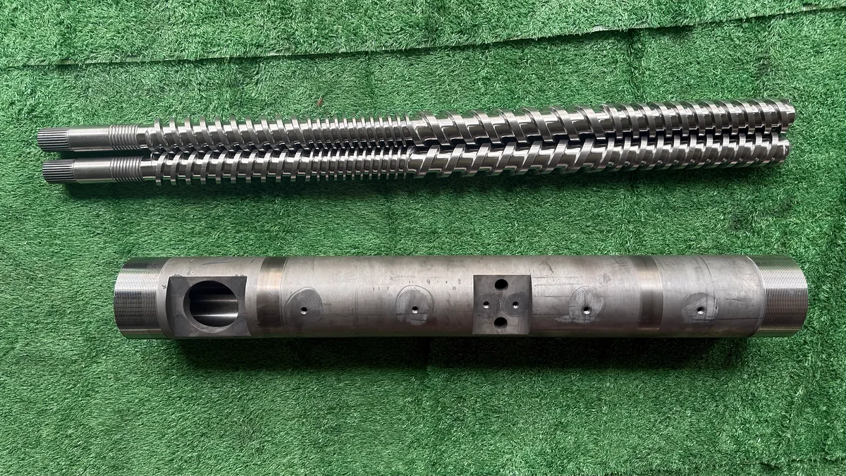
Parallel Twin Screw Extruder Parts That Fail First—And Why
Oct 29, 2026
Learn which parallel twin screw extruder parts fail first, how wear patterns reveal process issues, and how to source quality replacement screw elements and kneading blocks.
Read Article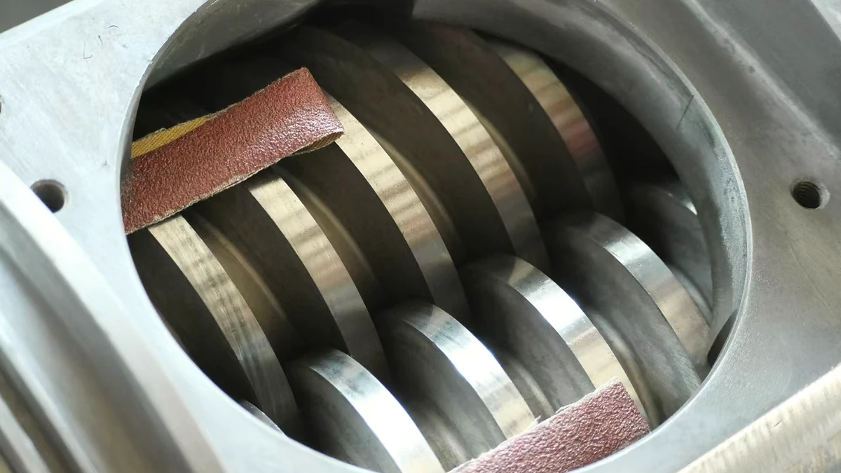
Why Your Conical Twin Screw Extruder Parts Wear Out Too Fast
Oct 28, 2026
Learn why conical twin screw extruder parts wear out fast. Full anatomy, wear analysis, material science, and maintenance checklist for PVC extrusion.
Read Article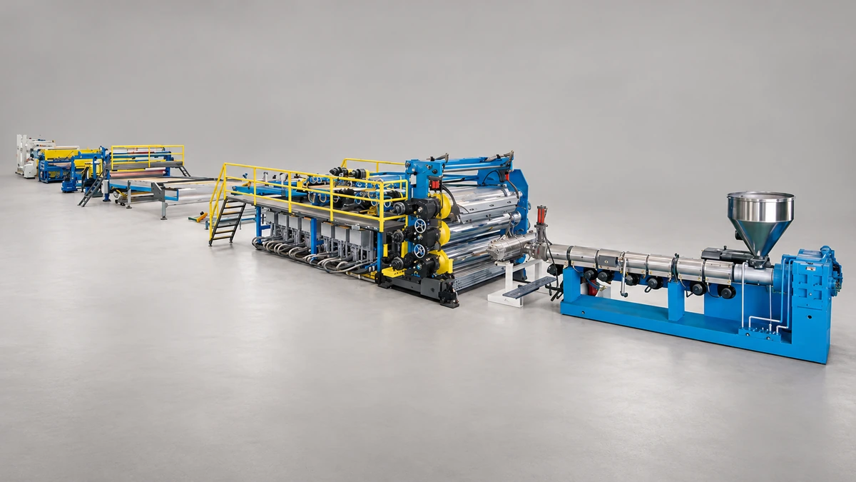
What No Supplier Tells You About Your Pet Sheet Extrusion Line
Oct 28, 2026
Learn what suppliers won't tell you about your PET sheet extrusion line — IV management, APET vs CPET setup, rPET processing, defect fixes, and buyer evaluation tips.
Read ArticleLooking for something else?
Search by material, symptom or product and jump straight to the relevant page.
These are navigation suggestions based on keyword matching — not a quotation, not a delivery commitment, and not a substitute for engineering review. Final specification is confirmed by our engineers against your drawings and processed material.
Need help with screw barrel selection?
Share your machine model, processed material and application. Our team can help with pricing and technical support.