

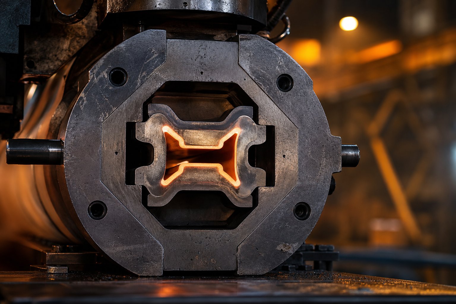
What Is an Extrusion Die and Why It Matters
Imagine squeezing toothpaste from a tube. The opening at the tip determines the shape of what comes out. An extrusion die works on the same principle, only at industrial scale, under extreme pressure, and with far greater precision.
What Is an Extrusion Die and How Does It Work
An extrusion die is a precision-engineered tool with a specially shaped opening that determines the cross-sectional geometry of material forced through it, producing continuous lengths of a uniform profile.
Whether the raw material is a heated aluminum billet or a stream of molten polymer, the process die performs the same essential function: it transforms shapeless material into a product with exact dimensions, consistent wall thickness, and repeatable quality. As the material is pushed through the die opening under pressure, it conforms to the cavity's geometry and emerges as a continuous extrudate, from simple round tubing to complex architectural profiles.
The design of this single component directly controls the final product's dimensions, surface finish, and mechanical properties. A poorly designed extruder die leads to warped profiles, uneven thickness, and costly scrap. A well-engineered one delivers flawless parts run after run.
Where the Die Fits in the Extrusion System
The die doesn't work in isolation. It sits at the downstream end of a tightly coordinated system. In metal extrusion, a hydraulic ram forces a preheated billet through the die at pressures that can reach thousands of tons. In polymer extrusion, a rotating screw melts and conveys plastic through a barrel and into the die under controlled temperature and pressure.
It's also important to distinguish between the die itself, the single steel disc or plate containing the shaped opening, and the full die assembly. The assembly includes supporting components such as backers, bolsters, feeder plates, and die rings that reinforce the die against enormous operating forces and ensure proper alignment. In aluminum extrusion, for example, a die stack may include a feeder plate to control metal flow, a backer for structural reinforcement, and bolsters to distribute pressure evenly across the tooling.
Here's a detail worth noting early: while the term "extrusion die" applies across both metal and polymer processing, the design philosophies behind each are fundamentally different. Metal dies must survive crushing mechanical loads, while polymer dies must manage complex melt behavior, temperature sensitivity, and material-specific flow characteristics. That distinction shapes virtually every decision in die engineering, from material selection to internal channel geometry.
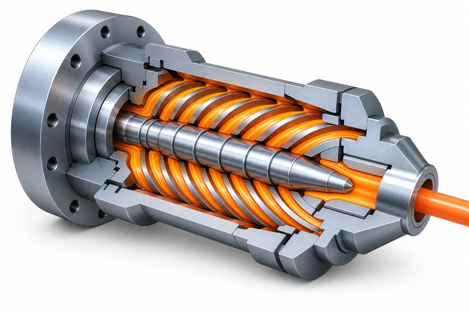
Complete Taxonomy of Extrusion Die Types
Every extruded product begins with a specific type of extrusion die head, and the variety of available designs is far broader than most people realize. The shape of the end product, whether it's a flat sheet of packaging film, a hollow pipe, or a complex window frame profile, dictates which die geometry makes sense. Understanding these categories helps you match the right tooling to the right application from the start.
Flat and Sheet Dies Including Cast Film Types
Flat dies produce wide, thin extrudates: sheets, films, coatings, and laminates. Two primary designs dominate this category.
The T-die uses a simple T-shaped manifold to distribute the polymer melt across the width of the opening. Its flow channel geometry is straightforward and relatively inexpensive to machine. You'll often find T-dies in extrusion coating applications. The trade-off? Melt distribution isn't particularly uniform, and the channel geometry isn't well streamlined, making it a poor choice for thermally sensitive polymers that degrade when exposed to uneven residence times.
The coat-hanger die solves that problem. Its manifold tapers from the center toward the edges in a shape resembling a coat hanger, with teardrop-shaped cross sections that progressively reduce to account for decreasing flow rates. This geometry delivers far more uniform melt distribution and is the standard for high-quality sheet and cast film extrusion. Cast film extrusion die type applications demand especially tight thickness tolerances, sometimes across widths exceeding 30 feet. To manage that precision, coat-hanger dies typically incorporate flex lip adjustments and choker bars that allow operators to fine-tune the final gap and flow distribution while the line is running.
Annular and Tubular Die Configurations
When the product has a hollow cross section, think pipes, tubing, blown film, or wire insulation, the die needs both an outer wall and an inner mandrel to form the annular channel. Three main configurations handle this.
The extrusion spider die uses radial legs (called spider legs) to support a central mandrel inside the die body. Melt flows around these legs and recombines on the other side, passing through a converging annular region before exiting the die. Spider dies are widely used in pipe production, but they come with a well-known design trade-off: every spider leg creates a weld line. These weld lines are mechanically weaker zones where the separated melt streams rejoin, and the re-entanglement time needed for full molecular healing can be substantially longer than typical relaxation times. Engineers mitigate this by placing spider legs far upstream from the die exit, using offset or tangential leg arrangements, or replacing legs with a screen plate containing many small holes.
The spiral mandrel die largely eliminates the weld line problem altogether. Instead of spider legs, it uses helical channels machined into the mandrel surface. These channels decrease in depth along the spiral path, forcing melt to leak progressively from one channel to the next. The result is thorough mixing and a nearly weld-free annular flow, which is why spiral mandrel designs are preferred for blown film and high-performance tubing where hoop strength matters.
The crosshead die redirects the melt flow 90 degrees from the extruder axis. This configuration is essential for wire coating, where a conductor passes through the center of the die and receives a polymer layer near the exit. Crosshead dies also serve side-fed pipe and tubing applications, with adjustable centering bolts that allow operators to fine-tune wall thickness concentricity.
Profile Dies and Specialty Configurations
Profile extrusion dies produce cross sections that aren't simple circles, rectangles, or annular shapes. Window frames, weather stripping, edge trim, heat sink fins: these all require custom-designed profile tooling where flow balancing becomes especially challenging.
Profile dies range from basic orifice dies, essentially a plate with the desired shape cut into it, to sophisticated tapered profile dies with gradually converging flow channels that maintain smooth velocity transitions. Orifice types are limited to inexpensive, low-tolerance products (often PVC or rubber), while tapered designs deliver the dimensional accuracy needed for precision applications at higher extrusion rates.
Co-extrusion dies represent another specialty category. These combine multiple polymer streams into a single layered product, common in packaging films where barrier properties, adhesion layers, and structural layers must all merge cleanly. The streams can be joined inside a shared die land, in an upstream adapter, or even outside the die entirely. The key engineering challenge is managing viscosity mismatches between layers; if one polymer is significantly less viscous than another, it will try to encapsulate the higher-viscosity component, distorting the layer structure.
| Die Type | Geometry | Typical Materials Processed | Common Applications | Complexity Level |
|---|---|---|---|---|
| T-Die | T-shaped manifold, flat exit slot | Polyolefins, general thermoplastics | Extrusion coating, basic sheet | Low |
| Coat-Hanger Die | Tapered manifold with teardrop cross section | PE, PP, PET, PVC, engineering resins | Cast film, precision sheet, laminates | Medium |
| Spider Die | Mandrel supported by radial legs, annular exit | PE, PP, PVC, ABS | Pipe, large-diameter tubing | Medium |
| Spiral Mandrel Die | Helical channels on mandrel, annular exit | PE, PP, PA, barrier resins | Blown film, high-performance tubing | High |
| Crosshead Die | 90-degree melt turn around central core tube | PE, PVC, fluoropolymers, TPEs | Wire coating, catheter tubing, side-fed pipe | Medium-High |
| Profile Die (Solid Die) | Custom-shaped opening, often with tapered approach | PVC, ABS, wood-plastic composites | Window frames, trim, gaskets, channels | High |
| Co-Extrusion Die | Multiple feed ports merging into layered exit | Multi-layer PE, EVOH, adhesive tie layers | Barrier packaging, multi-layer sheet and film | Very High |
Each of these extrusion dies exists because no single geometry can serve every product. A coat-hanger manifold that perfectly distributes melt across a wide flat sheet would be entirely wrong for forming a hollow pipe, and a spiral mandrel channel that eliminates weld lines in blown film has no role in profile extrusion. The internal flow channel dictates what the die can produce, and that geometry is inseparable from the material being processed and the forces acting on it.
Those forces vary dramatically depending on whether you're pushing heated aluminum through hardened steel at enormous pressure or guiding a viscoelastic polymer melt through carefully streamlined channels at far lower loads. That distinction between metal and polymer extrusion dies shapes nearly every aspect of die engineering.
Metal Versus Polymer Extrusion Dies
The forces acting on an aluminum extrusion die bear almost no resemblance to those experienced by a polymer die producing PVC window profiles on the same factory floor. Yet both tools share the same name. Understanding why they diverge so sharply in design, material choice, and operating life is essential for anyone specifying or maintaining extrusion tooling.
Aluminum and Metal Extrusion Die Characteristics
Picture a softened aluminum billet being rammed through a hardened steel disc at pressures that can exceed 100,000 psi. That's the reality for aluminum extrusion dies. Billets are typically preheated to roughly 700-930°F (370-500°C), and hydraulic presses apply forces up to 15,000 tons to push the metal through the die opening. Under those conditions, the tooling faces a brutal combination of thermal cycling, abrasive wear, and compressive stress that would destroy most engineering materials within minutes.
This is why virtually all aluminium extrusion dies are machined from premium hot-work tool steel, predominantly H13. Its combination of high-temperature hardness, thermal fatigue resistance, and toughness makes it the industry standard. Supporting components like backers and bolsters absorb the remaining load, but the die face itself endures the most punishing contact with hot metal.
Bearing length plays a specific role here: it controls how fast different sections of the profile exit the die. Thicker portions of the cross section flow more easily, so designers assign them longer bearing surfaces to increase friction and slow the metal down. Thinner legs get shorter bearings. The goal is simple: every part of the profile should emerge at the same velocity to prevent warping, twisting, or tearing of the extrudate.
A well-maintained aluminum extrusion die typically lasts for several hundred billets before it needs correction, and it may be reworked and returned to service multiple times before final retirement.
Polymer and Plastic Extrusion Die Differences
Polymer extrusion dies operate in a fundamentally different regime. Pressures rarely exceed 5,000 psi, and processing temperatures are far lower, generally between 300-550°F (150-290°C) depending on the resin. So why aren't plastic dies simpler?
Because polymers are viscoelastic. Unlike metals, which deform plastically and hold their shape once through the die, polymer melts have molecular memory. As the extrudate exits the die opening, the stretched and oriented molecular chains recoil toward their original coiled state. This phenomenon, known as die swell, causes the product to expand beyond the die dimensions, sometimes by 10-30% or more. Die designers must compensate for this by undersizing certain features, adjusting land length, and carefully controlling shear rates at the exit.
Bearing length in polymer dies serves a different purpose than in metal extrusion. Rather than modulating exit velocity, it primarily manages polymer relaxation. A longer land gives the melt more time to relax internal stresses before exiting, which reduces die swell and improves surface quality. Too short a land, and you'll see melt fracture, a surface distortion ranging from fine roughness (shark skin) to severe, irregular deformation that ruins the product.
The PVC extrusion die presents a unique additional challenge. When PVC is processed at elevated temperatures, especially if the melt overheats or experiences excessive shear, it thermally degrades and releases hydrogen chloride (HCl) gas. This acidic byproduct attacks standard tool steels from the inside, corroding flow channels and bearing surfaces. Consequently, PVC dies demand specialized corrosion-resistant coatings, careful temperature control, and more frequent maintenance intervals than dies used for polyethylene or polypropylene.
| Parameter | Aluminum/Metal Extrusion Dies | Polymer/Plastic Extrusion Dies |
|---|---|---|
| Operating Temperature | 700-930°F (370-500°C) | 300-550°F (150-290°C) |
| Pressure Range | 50,000-150,000+ psi | 1,000-5,000 psi |
| Primary Material Challenges | Thermal fatigue, abrasive wear, extreme compressive stress | Viscoelastic flow, die swell, melt fracture, corrosion (PVC) |
| Typical Die Material | H13 hot-work tool steel (44-52 HRC) | H13, 4140, stainless steels; corrosion-resistant coatings for PVC |
| Lifespan | Hundreds of billets per service cycle; multiple rework cycles | Thousands to tens of thousands of operating hours with maintenance |
You'll notice that aluminum extrusion dies live and die by mechanical strength, while polymer dies live and die by flow management. Both require precision engineering, but the problems they solve are almost opposite in nature. One fights crushing force; the other fights molecular behavior.
Whichever domain you're working in, the die material itself is the foundation of performance and longevity. The specific tool steel grade, its heat treatment, and any surface coatings applied to it determine how long a die can hold tolerances under the stresses just described.
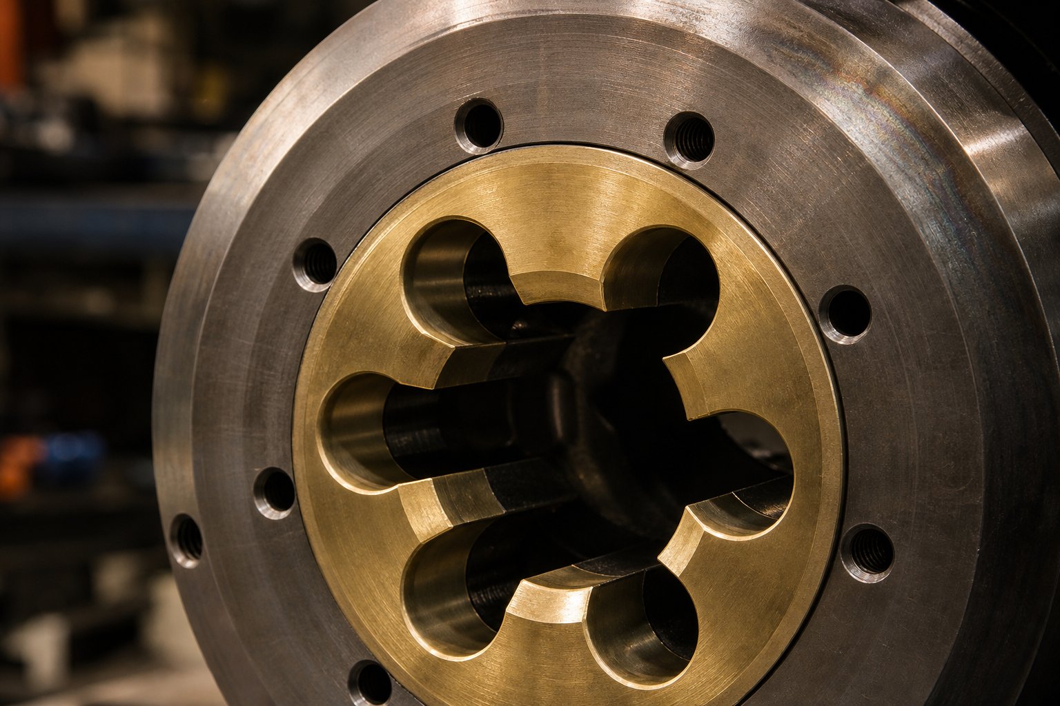
Die Materials and Surface Treatments Explained
A die's geometry determines the shape of your product. But the steel it's made from, and the coatings applied to its surfaces, determine how long that shape stays accurate. Choose the wrong material for your operating conditions, and even a perfectly designed tool will wear out in a fraction of its expected life. Choose wisely, and you can push the same industrial die through tens of thousands of production cycles with minimal correction.
Tool Steel Grades for Extrusion Dies
Not all tool steels are created equal, and the extrusion industry relies on a small handful of grades, each selected for a specific balance of properties. The three you'll encounter most often are H13, H11, and D2.
H13 (1.2344 / SKD61) is the workhorse of hot-work extrusion tooling. It's the default choice for aluminum extrusion dies, shaped dies, tubing dies, containers, mandrels, and dummy blocks. Why? Because H13 delivers an exceptional combination of hot strength, toughness, thermal shock resistance, and nitriding response. It holds its hardness at temperatures above 1,000°F and resists the thermal fatigue cracking (heat checking) that destroys lesser steels under repeated heating and cooling cycles. For aluminum extrusion, where die face temperatures regularly exceed 900°F, H13 remains the industry standard worldwide.
H11 (1.2343 / SKD6) is closely related to H13 but trades a small amount of wear resistance for improved toughness. That makes it the preferred grade for complex die geometries, think bridge dies, spider dies, and any tooling with thin sections or sharp transitions that are prone to brittle fracture under the intense pressures of the extrusion press. When the risk of cracking outweighs the risk of surface wear, experienced toolmakers reach for H11.
D2 occupies a different niche entirely. It's a cold-work tool steel with very high wear resistance and edge retention, but limited toughness and poor performance at elevated temperatures. You'll find D2 in cold extrusion tooling, cutting blades, and trimming tools, but rarely in hot extrusion dies. For plastic die applications that operate at moderate temperatures and face abrasive fillers like glass fiber or mineral-filled compounds, D2 can deliver excellent service life.
For more demanding thermal environments, such as copper and brass extrusion, H21 tool steel offers superior red hardness, the ability to maintain strength at temperatures where H13 begins to soften. Some extreme applications even call for M2 high-speed steel, though the cost premium limits its use to situations where nothing else survives.
Hardness is typically specified on the Rockwell C (HRC) scale. Most hot-work extrusion dies operate in the 44-52 HRC range after heat treatment. Higher hardness resists wear and deformation but increases brittleness. Lower hardness improves toughness but accelerates surface erosion. The specific target depends on the extruded material, profile complexity, and production volume. Getting this balance right is one of the most consequential decisions in extrusion tooling engineering.
Surface Treatments and Protective Coatings
Even the best tool steel benefits enormously from surface treatments that enhance hardness, reduce friction, and resist corrosion. These treatments can double or triple the service life of a die at a fraction of the cost of replacement.
Nitriding is the most widely used surface treatment for extrusion dies. The process diffuses nitrogen atoms into the steel surface at temperatures around 950-1,050°F, creating a hard, wear-resistant case without significantly affecting core toughness. Nitrided surfaces typically reach 65-70 HRC, far harder than the underlying substrate, and the treatment also improves resistance to adhesive wear where hot aluminum tends to stick to the die bearing. Most aluminum extrusion operations re-nitride their dies as part of routine maintenance to restore the hardened surface layer after it wears down.
Chrome plating serves a dual purpose: it provides excellent corrosion resistance and significantly reduces friction between the die surface and the material flowing through it. This makes chrome-plated dies especially valuable for PVC extrusion, where HCl gas released during processing would otherwise attack bare tool steel. The low coefficient of friction also promotes smoother flow and better surface finish on the extrudate.
PVD and CVD coatings represent the cutting edge of die surface protection. Physical Vapor Deposition (PVD) applies thin, extremely hard coatings such as TiN (titanium nitride), TiAlN (titanium aluminum nitride), or CrN (chromium nitride) at relatively low temperatures, preserving the die's dimensional accuracy. CVD (Chemical Vapor Deposition) operates at higher temperatures and produces thicker, more adherent coatings. Both technologies dramatically improve wear resistance, oxidation resistance, and thermal stability, making them increasingly common for high-volume production where die longevity directly impacts profitability.
When selecting materials and coatings for any extrusion die, four factors should drive the decision:
- Operating temperature - Hot-work grades (H13, H11, H21) for elevated temperatures; cold-work grades (D2) for ambient or low-temperature operations
- Extruded material abrasiveness - Glass-filled polymers, hard alloys, and mineral-loaded compounds demand harder surfaces and more aggressive coatings
- Production volume - High-volume runs justify premium steel grades and multi-layer coatings; short runs may not recover the investment
- Cost constraints - Nitriding offers excellent value for most applications; PVD/CVD coatings cost more but deliver proportionally longer service life in demanding conditions
The gap between a soft, untreated die and a properly specified one is staggering. An untreated die in aluminum extrusion might last only a few hundred billets before requiring correction. The same die geometry machined from premium H13, properly heat-treated to the right HRC, and nitrided after finishing can process several thousand billets per service cycle, with multiple rework cycles extending total life even further. For plastic die applications running abrasive compounds, the difference between a bare tool and one with a PVD coating can mean the difference between weeks and months of continuous production.
Material and coating selection sets the stage, but the die still needs to be manufactured with precision. The journey from a raw block of tool steel to a finished extrusion die involves a carefully sequenced set of machining, heat treatment, and finishing operations, each of which directly affects how the final tool performs in production.
Extrusion Die Design Principles and Flow Balancing
A die can be machined from the finest H13, nitrided to perfection, and polished to a mirror finish, yet still produce warped, dimensionally inconsistent extrudate if the internal flow channels aren't engineered correctly. Why? Because extrusion die design ultimately comes down to one deceptively simple goal: making every part of the material exit the die opening at exactly the same speed.
Sounds straightforward. In practice, it's one of the most demanding challenges in manufacturing engineering. Thick sections of a profile flow more readily than thin ones. Central regions receive more pressure than edges. Material near the die wall moves more slowly than material at the core. Every one of these imbalances, left unchecked, distorts the extrudate the moment it leaves the die. Understanding the principles engineers use to counteract these tendencies is the key to understanding why some dies produce flawless parts and others produce scrap.
Flow Balancing and Uniform Velocity Distribution
Flow balancing, the practice of achieving uniform exit velocity across the entire die opening, is the single most critical factor in extrusion die design quality.
Imagine you're extruding an L-shaped aluminum profile. The thick leg of the L has a large cross-sectional area, so material flows through it with less resistance. The thin leg restricts flow, creating more friction. If you don't compensate for this difference, the thick leg exits faster than the thin one. The result? The profile curves, twists, or tears apart as it emerges from the die. The same principle applies to any asymmetric shape, whether you're working with an extruding die for complex polymer profiles or aluminum structural members.
Engineers achieve flow balance through several interconnected techniques:
- Bearing length variation - The most fundamental tool. Increasing bearing length in high-flow zones adds frictional resistance, slowing the material down. Decreasing it in restricted zones speeds flow up. In aluminum die extrusion, thicker areas of the profile receive longer bearings to match the speed of thinner areas, sometimes varying from 2 mm to over 20 mm within a single die.
- Entry angle optimization - The approach angle, the taper leading into the bearing zone, controls how aggressively material accelerates as it converges toward the die opening. Steeper angles increase velocity and pressure drop. Shallower angles promote smoother, more gradual flow transitions.
- Flow restrictors and feeders - In aluminum extrusion, feeder plates (also called weld plates) placed upstream of the die control the contour and spread of metal entering the die opening. In polymer dies, flow restrictors such as choker bars and adjustable lips serve a similar purpose, throttling flow in over-fed regions.
- Channel geometry shaping - The internal channel cross section itself can be sculpted to redistribute material. Coat-hanger dies, for instance, use progressively tapered manifold cross sections to equalize flow across the full width of a sheet die.
The interplay between these techniques is what makes die extrusion design more art than formula. Changing one parameter, say, lengthening a bearing in one zone, alters pressure distribution upstream, which can shift flow patterns in adjacent zones. Experienced die designers develop an intuition for these cascading effects over years of practice, though modern computational tools are steadily reducing reliance on trial and error.
Critical Design Parameters and Their Effects
Several technical terms describe the geometry of an extrusion die's internal features. You'll encounter them constantly in die engineering literature, on shop floors, and in conversations with toolmakers. Here's what each one means and why it matters:
- Bearing (land) - The parallel-walled section of the die opening where the material makes final contact before exiting. Its length directly controls exit velocity and surface finish. Longer bearings increase resistance and slow flow; shorter ones reduce resistance and speed it up.
- Pre-land - A slightly oversized section immediately upstream of the bearing. It relieves pressure gradually before the material enters the tight bearing zone, reducing the risk of surface tearing in metals or melt fracture in polymers.
- Approach angle - The converging taper between the die's entry face and the bearing zone. Typical angles range from 15 to 45 degrees. The steeper the approach, the sharper the acceleration and the higher the localized shear rate.
- Choke - A deliberate narrowing of the bearing dimension, effectively tightening the opening slightly. Engineers use chokes to slow down specific portions of the profile that are running too fast. Even a few thousandths of an inch of choke can meaningfully alter flow distribution.
- Relief (back relief) - An enlargement of the channel behind the bearing, on the exit side. Relief prevents the extrudate from dragging against the die after it passes the bearing, which would introduce friction marks, surface defects, or dimensional distortion. Without adequate relief, soft materials like aluminum or low-viscosity polymers can stick and smear.
These parameters don't operate independently. A change in bearing length affects the optimal approach angle. Adding choke in one zone shifts pressure and flow to neighboring regions, potentially requiring relief adjustments elsewhere. Extrusion die design is a system-level problem where every dimension is coupled to every other.
Die swell adds another layer of complexity, particularly in polymer extrusion. When a viscoelastic melt passes through the die, molecular chains are stretched and oriented by shear forces. The instant those chains exit the bearing, they spring back toward their relaxed state. The extrudate swells, sometimes by 10-30% beyond the die opening dimensions. Designers compensate by undersizing the die aperture relative to the desired product dimensions, but the amount of compensation depends on the polymer type, shear rate, melt temperature, and bearing length. A research study on profile extrusion die optimization highlights that post-extrusion phenomena like swell remain one of the key variables affecting the quality of extruded profiles and must be accounted for during the design phase.
Pressure drop across the die also influences channel sizing. Every restriction, every bearing surface, and every change in channel cross section consumes pressure. If the total pressure drop through the die exceeds the available driving pressure from the extruder or press, flow stalls, output drops, or the product dimensions fall out of specification. Engineers balance two competing demands: channels narrow enough to maintain velocity and shear for proper material forming, yet wide enough to keep total pressure drop within the system's capability.
Simulation-driven design is rapidly changing how these trade-offs get resolved. Traditionally, extrusion die design relied heavily on designer experience, hand calculations, and physical trial runs, a process that could consume weeks of machine time and multiple die corrections. Finite Element Analysis (FEA) allows engineers to model the die's structural response to pressure and thermal loads before the first cut of steel. Computational Fluid Dynamics (CFD) goes further, simulating material flow through the die channels to predict velocity distribution, pressure profiles, and temperature gradients across the entire cross section.
A computational framework developed at the University of Minho demonstrated that HPC-driven optimization could automatically test hundreds of alternative die geometries within a single day, achieving a 3.8x improvement in flow balance compared to the initial design. Their industrial partner confirmed that the computationally optimized die produced a satisfactory profile on the very first trial, a result that typically required at least five experimental iterations using traditional methods. The computational cost of roughly 177 euros was negligible compared to the approximately 19,000 euros total development cost of the die.
AI and machine learning are pushing this evolution further. Data-driven approaches can learn complex patterns within large datasets of process parameters and corresponding die designs, predicting optimal geometries for new profile requirements without starting from scratch. These tools don't replace the designer's judgment, but they compress the design cycle from weeks to hours and dramatically reduce the scrap and machine time consumed by trial-and-error correction.
Even the most sophisticated simulation, however, produces a design that still must be built. The journey from optimized digital model to physical precision tool involves a carefully sequenced set of manufacturing operations, each carrying its own tolerances, challenges, and quality control requirements.
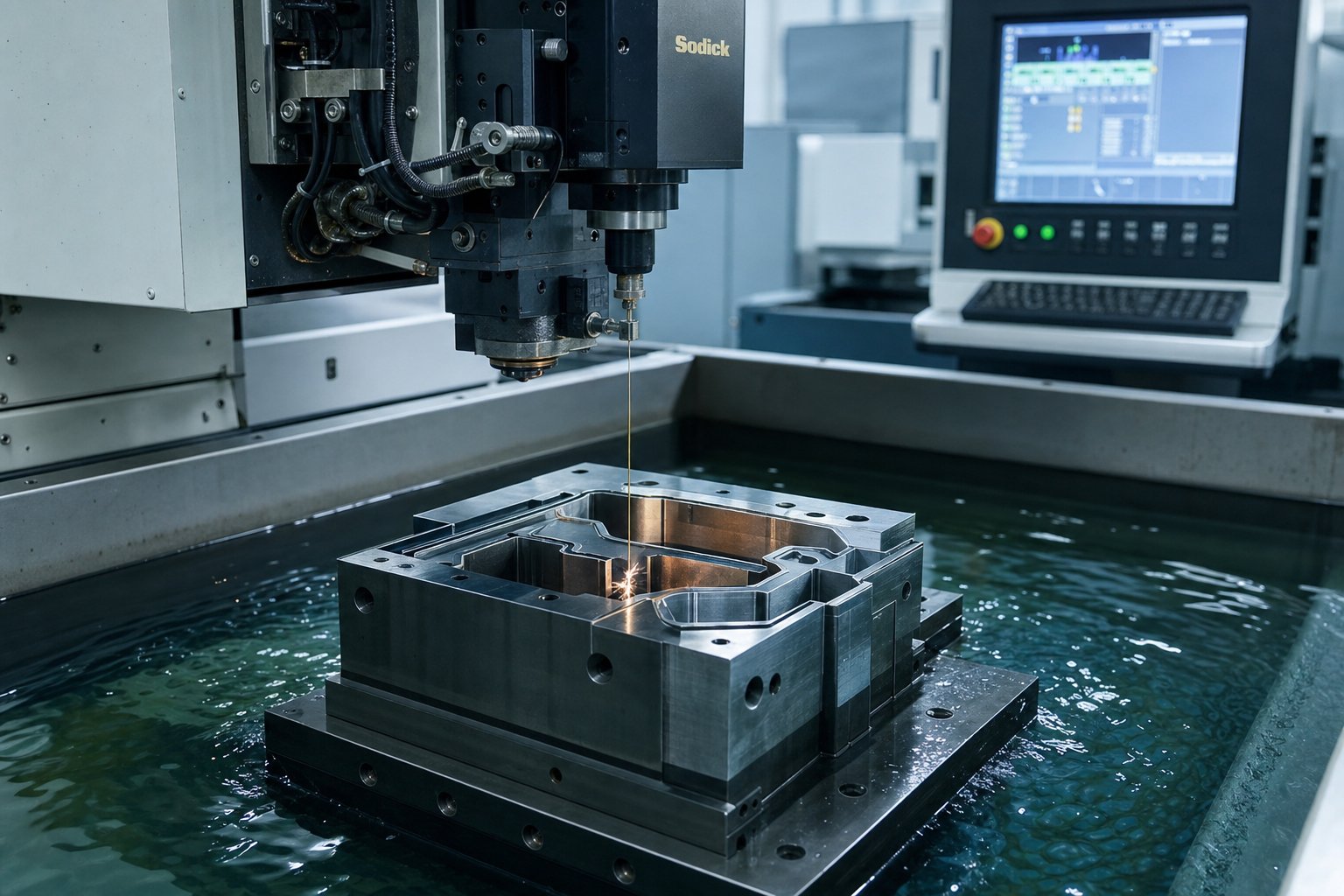
How Extrusion Dies Are Manufactured
A flawless die design is only as good as the manufacturing process that brings it to life. Every extrusion die starts as a block of premium tool steel and passes through a tightly controlled sequence of operations before it's ready for production. Skip a step, rush the heat treatment, or tolerate sloppy surface finish, and even the most carefully optimized flow geometry won't deliver consistent parts. So how do solid die manufacturers actually build these precision tools?
The process follows a logical progression, from rough shaping to final finishing, with each stage building on the accuracy of the one before it:
- Blanking and forging - The journey begins with cutting a tool steel billet, typically H13 for hot-work applications, to approximate size. For high-performance plastic extrusion tooling and metal dies alike, the billet is then forged to refine its grain structure and eliminate internal voids. As hot extrusion die metallurgy guidelines emphasize, careful control of forging temperature and holding time is critical at this stage to avoid decarburization, which weakens the surface and can cause premature failure.
- Preliminary heat treatment (annealing) - The forged blank undergoes annealing to soften the steel for machining and to produce a uniform, fine-grained microstructure. This step ensures round, evenly distributed carbides within the steel matrix, a detail that directly influences the die's toughness and wear resistance after final hardening. Some blanks receive a high-temperature quench-and-temper cycle after forging to further improve fracture toughness before any metal is cut.
- Rough machining via CNC milling - Multi-axis CNC mills remove the bulk of excess material, shaping the die's exterior geometry, bolt holes, locating features, and rough internal channels. This stage prioritizes speed and material removal rather than precision, leaving a small amount of stock for finish operations.
- Precision profiling via wire EDM - This is where the real magic happens. Wire Electrical Discharge Machining uses a thin, electrically charged wire to cut intricate shapes by spark erosion, not mechanical contact. Wire EDM is indispensable for both polymer and metal extrusion dies because it can produce the complex internal flow channels, tight-tolerance apertures, and sharp internal corners that conventional milling cannot reach. For poly-dies with spiral mandrel channels or multi-port co-extrusion manifolds, wire EDM is often the only viable method for achieving the required geometry. In aluminum dies, it cuts the precise bearing profiles and relief contours that control metal flow velocity across the die face. Tolerances of plus or minus 0.0002 inches are routine with modern wire EDM equipment.
- Grinding - Surface grinding refines flat faces and critical datum surfaces to the final dimensional tolerance, ensuring proper fit within the die stack assembly. Cylindrical and profile grinding may also be used to true up bearing surfaces and achieve the surface finish quality needed for smooth material flow.
- Final heat treatment (hardening) - The fully machined die enters a carefully controlled hardening cycle. For H13 steel, this involves austenitizing at the appropriate temperature, quenching via oil or air cooling, and then double tempering. Tempering is typically performed twice, with the second cycle 10-20 degrees Celsius lower than the first, and each hold calculated at roughly 3 minutes per millimeter of die thickness with a minimum of 2 hours. The die must be tempered as soon as possible after quenching, especially for complex geometries, since allowing the surface temperature to drop below 80 degrees Celsius without tempering risks residual stress buildup and cracking. The target hardness, typically 44-52 HRC for hot-work dies, balances wear resistance against the toughness needed to survive thermal cycling.
- Finish machining and polishing - After hardening, minor dimensional corrections are made through finish grinding or light EDM passes. Flow channel surfaces are then hand-polished or machine-lapped to reduce surface roughness, minimize friction, and prevent material from sticking during extrusion. For polymer dies especially, mirror-quality channel finishes dramatically improve extrudate surface appearance.
- Surface treatment and coating application - The final manufacturing step applies protective treatments discussed in the previous chapter: nitriding for surface hardness, chrome plating for corrosion resistance, or PVD/CVD coatings for extended wear life. The specific treatment depends on the die's intended application and the material it will process.
Machining Methods for Die Production
Among all these steps, wire EDM deserves special emphasis because it transformed what's possible in die manufacturing. Before EDM technology became widespread, complex internal geometries had to be approximated through combinations of drilling, broaching, and hand filing, a slow, skill-dependent process with inherent accuracy limitations. Modern wire EDM systems cut virtually any two-dimensional profile directly from hardened or pre-hardened steel with repeatable precision. Sinker EDM, a related process, extends this capability to three-dimensional cavities by using shaped electrodes to erode material in complex contoured pockets.
For plastic extrusion tooling with intricate flow splitter geometries or multi-layer co-extrusion channels, these electrical discharge methods are not merely convenient, they're essential. No rotary cutting tool can reach inside a spiral mandrel die's helical channels or machine the fine flow distribution ports inside a coat-hanger manifold to the required tolerances.
Heat Treatment and Finishing Processes
Heat treatment is arguably the most consequential step in the entire sequence. You can re-machine a surface or re-polish a channel, but an improperly hardened die has a compromised metallurgical structure that no amount of rework can fix. The austenitizing temperature must be precise enough to dissolve the right amount of carbon and alloy elements into solution without promoting excessive grain growth. Quenching must be fast enough to achieve the desired transformation but controlled enough to avoid distortion or cracking, particularly in dies with thin sections or abrupt geometry transitions.
The double tempering cycle isn't optional. It transforms brittle as-quenched martensite into tempered martensite with significantly improved toughness, and it relieves the internal stresses locked into the steel during rapid cooling. Skipping the second temper or rushing the cycle leads to dies that crack under thermal cycling on the extrusion press, sometimes catastrophically during the first production run.
Quality control runs through every stage, not just the end of the process. Dimensional inspection using coordinate measuring machines (CMMs) verifies critical features after machining and again after heat treatment, since hardening can cause slight dimensional shifts. Flow simulation validation compares the as-built die geometry against the original CFD-optimized design to flag any deviations that could affect velocity distribution. And the ultimate test is the trial extrusion run: pushing actual material through the finished die under production conditions to verify profile dimensions, surface quality, and flow balance. These trial runs often reveal subtle issues, a slightly fast-running section, a minor surface blemish, that require one or two rounds of correction before the die enters full production.
Looking ahead, additive manufacturing is beginning to carve out a niche in die production. Metal 3D printing technologies such as selective laser melting (SLM) can build die components with internal features that are impossible to machine conventionally, most notably conformal cooling channels that follow the contours of the die's flow surfaces rather than being limited to straight drilled holes. Conformal cooling delivers more uniform temperature control across the die face, reducing hot spots that cause uneven flow, thermal degradation, and accelerated wear. While the technology isn't yet cost-effective for entire production dies, it's increasingly used for inserts, mandrel tips, and specialized cooling components within larger die assemblies.
Even a perfectly manufactured die, however, doesn't stay perfect forever. The moment material starts flowing through it, wear begins, and the clock starts ticking toward the first maintenance intervention. Knowing when and how to maintain, correct, and ultimately replace extrusion tooling is what separates operations that run smoothly from those that chase quality problems batch after batch.
Die Maintenance and Correction Best Practices
Every production cycle chips away at the precision that was built into your tooling during manufacturing. Bearing surfaces erode under abrasive metal flow. Polymer residues carbonize in flow channels. Heat checking creeps across stressed surfaces one thermal cycle at a time. Left unaddressed, these small degradations snowball into dimensional drift, surface defects, and eventually scrapped product. The difference between a plant that catches problems early and one that reacts to quality failures comes down to a disciplined, structured approach to die maintenance.
Routine Die Maintenance Procedures
Think of routine maintenance as the foundation that prevents costly surprises. Every time a plastic extruder die or metal die comes off the press, it should pass through a consistent sequence of inspection and care before returning to service.
Cleaning residual buildup is always the first step. In aluminum extrusion, oxide scale and adherent metal accumulate on bearing surfaces, undercuts, welding chambers, and port openings. Industry practice calls for cooling the die fully and then immersing it in a caustic soda bath at 60-80 degrees Celsius for approximately eight hours to dissolve aluminum oxide deposits. Rushing this step, pulling the die from the bath early or skipping it entirely, leaves blockages that produce die lines, pickup defects, and uneven flow on the next run. For plastic dies, degraded polymer residue must be purged or mechanically removed from flow channels. Carbonized material is especially stubborn and, if left in place, breaks loose during production and contaminates the extrudate.
After cleaning, bearing surface inspection reveals how the die actually performed. Experienced die correctors look for two distinct forms of wear. Erosion appears as general surface degradation across broad areas, while bearing washout shows up as localized craters or linear depressions where material flow was most aggressive. A three-year statistical study of a medium-to-large aluminum extrusion facility found that bearing washout accounted for 87% of all correctable wear defects, making it the single most common wear-related problem on the production floor.
Checking for heat checking is equally critical. Heat checking, those fine networks of surface cracks caused by repeated thermal cycling, weakens bearing surfaces progressively. Small cracks may be tolerable for a few more runs, but once they propagate into deeper fissures, the die becomes prone to sudden fracture. Inspectors use visual examination, straight edges, and try-square sets to assess crack depth and distribution. Bearing cracks alone represented 75% of all correctable fracture defects in the same industry study.
Dimensional verification closes the inspection loop. Pin gauges, Vernier calipers, micrometers, and feeler gauges confirm that the die's critical features, bearing length, port dimensions, cavity geometry, and clearances, still fall within tolerance. When measurements start trending toward the upper limit, it's a signal that correction is needed before the next production campaign, not during it.
Once inspection is complete, cleaned dies are polished with 320-600 grade emery cloth, re-nitrided if hardness levels have dropped, and coated with a protective lubricant such as graphite spray or medium-weight oil before storage. This cycle of clean, inspect, polish, harden, and protect forms the backbone of every well-run die shop.
Die Correction and Reworking Techniques
When inspection reveals problems beyond normal surface wear, targeted correction operations bring the die back into specification. The skill of the die corrector matters enormously here. One improperly executed correction can cascade into additional defects. In fact, errors during correction operations were identified as the single largest category of correctable die defects, accounting for roughly 32% of all repair events in the three-year plant study, ahead of even wear and fracture.
Several proven techniques address specific problems:
Shimming and bearing adjustment correct flow distribution imbalances. If one section of the profile exits faster than another, shortening the bearing in the slow zone or choking the bearing in the fast zone rebalances velocity. Shortening is done by milling and grinding to reduce frictional contact area. Choking, a more delicate operation, involves filing a slight angle into the bearing to constrict flow. Because the adjustments involved are often just thousandths of an inch, choking is typically reserved for highly skilled technicians and is avoided whenever shortening alone can solve the problem.
Polishing bearing surfaces reduces friction in targeted areas, which subtly increases flow velocity through those zones. After every production cycle, polishing with properly squared emery cloth restores surface finish. If the cloth or file isn't aligned perfectly perpendicular to the bearing, the edges can roll or tip, inadvertently creating an unwanted choke or relief that worsens the very problem you're trying to fix.
Re-cutting or deepening channels compensates for accumulated wear or design shortcomings. Undercutting the mandrel widens flow passages and relieves blockages, while increasing chamber depth near bridge sections improves metal feed to starved regions. Machining and skimming operations, typically performed with diamond-tipped tools due to the high hardness of nitrided H13 steel, can reshape port holes, ribs, and bearing profiles. Each of these material-removal operations must be executed conservatively, leaving enough stock for future corrections.
Nitriding correction addresses hardness loss, a problem that silently undermines die performance. As repeated extrusion cycles wear through the hardened case, bearing surfaces soften and become more vulnerable to washout and plastic deformation. Re-nitriding restores surface hardness to the target range of approximately 63-64 HRC for H13 steel. It's also applied after welding repairs to strengthen newly added material. The key is timing: re-nitriding should follow a calculated schedule based on production throughput, not be deferred until quality problems appear.
Welding and grafting handle more severe damage. Fractured tongues, chipped bearings, and cracked ribs can sometimes be repaired using gas tungsten arc welding (GTAW), ideally after annealing the die to 550-650 degrees Celsius to minimize thermal stress cracking in the weld zone. A replacement feature is machined from the same tool steel grade, welded into position, and then re-machined to the original dimensions. It's a salvage operation, not a permanent fix, but it can extend a die's useful life significantly when the alternative is scrapping expensive tooling.
A core principle governs all correction work: corrections should be made at the back end of the die whenever possible. Working on the front face reduces remaining die life and limits future correction options. Every modification must also be thoroughly documented so the next corrector understands what has already been done and how much room remains for further adjustment.
The harder question isn't how to correct a die but when to stop correcting and replace it instead. Every rework removes material, shifts dimensions slightly, and narrows the margin for future adjustments. At some point, the cumulative changes push the die past the threshold of reliable performance. Watch for these warning signs:
- Visible heat checking that has progressed beyond surface-level cracks - Deep thermal fatigue cracks compromise structural integrity and cannot be reliably repaired
- Dimensional drift beyond acceptable tolerance limits - When repeated corrections have consumed the available adjustment range and measurements still trend out of spec
- Inconsistent product quality despite recent corrections - If extrudate dimensions, surface finish, or mechanical properties fluctuate unpredictably from run to run, the die's geometry has likely degraded beyond recoverable limits
- Excessive correction history - A die that has been through numerous rounds of bearing shortening, choking, welding, and re-nitriding has progressively less original material and less dimensional headroom for further work
- Hardness that cannot be restored to specification - When re-nitriding no longer brings the bearing surface back to the required HRC range, the underlying substrate has softened beyond recovery
Replacing a worn die is always more expensive in the short term than attempting one more correction. But running a compromised tool generates scrap, wastes machine time, and risks damaging downstream equipment. Experienced plant engineers weigh the cost of a new die against the cumulative cost of continued quality problems and usually find that earlier replacement pays for itself within a few production campaigns.
Knowing when maintenance ends and replacement begins is one half of the equation. The other half, choosing the right die for the job in the first place, is what determines how many production cycles you get before that decision ever has to be made.
How to Select the Right Extrusion Die for Your Application
Selecting an extrusion die isn't a catalog browsing exercise. Every variable, the material you're extruding, the complexity of the profile, the production volume you're targeting, the tolerances your customers demand, feeds into a decision that determines product quality and cost-per-part for years to come. Get it right, and your line runs predictably with minimal correction. Get it wrong, and you're chasing quality issues, burning through maintenance budgets, and losing production time to avoidable rework.
Yet many engineers and plant buyers make this decision based on habit or price alone. A structured selection methodology removes guesswork and ensures the tooling matches the actual demands of the job.
Matching Die Type to Application Requirements
Start with the material. The resin or alloy you're processing narrows your options immediately. A die for plastic extrusion running glass-filled nylon faces entirely different wear patterns than one processing unfilled polyethylene. A die for aluminium extrusion must survive pressures fifty times higher than its polymer counterpart. Material properties, viscosity, abrasiveness, thermal sensitivity, and die swell characteristics, dictate both the die geometry and the steel grade it should be machined from.
Profile complexity is the next filter. Simple shapes like round tubing or flat sheet can often be produced with straightforward annular or coat-hanger dies. Complex cross sections, think multi-hollow window profiles, asymmetric structural members, or co-extruded barrier packaging, require sophisticated flow channel engineering that adds design time, machining cost, and correction effort. The more intricate the geometry, the more critical flow balancing becomes and the more skilled the die designer needs to be.
Consider these five selection criteria in sequence:
- Extruded material properties - Melt viscosity, thermal stability, abrasive filler content, and die swell behavior determine both the internal channel geometry and the die material grade required
- Profile geometry and complexity - Solid profiles are simpler and cheaper than hollow ones. Multi-hollow or multi-layer co-extrusion configurations sit at the top of the complexity scale
- Production volume - High-volume, continuous runs justify premium tooling investments that reduce per-part cost over time. Short runs or prototyping favor simpler, more economical options
- Tolerance requirements - Tight tolerances demand precision machining, premium steel grades, and more frequent maintenance, all of which increase upfront and ongoing costs
- Budget constraints - The initial die cost is only part of the equation. Total cost of ownership includes maintenance, correction frequency, downtime, and eventual replacement
When does a standard catalog die suffice? If you're producing common shapes, round tubes, rectangular channels, standard angle bars, or basic sheet, using widely available alloys or commodity resins, off-the-shelf tooling often delivers acceptable results at a fraction of the cost of custom engineering. Standard plastic extrusion dies for basic pipe and tubing are readily available from multiple suppliers with lead times measured in days rather than weeks.
Custom engineering becomes necessary when your profile includes proprietary geometry, when tolerance requirements exceed standard capabilities, when you're co-extruding multiple materials, or when the production environment introduces unusual demands like corrosive resins or extreme operating temperatures. Custom dies offer greater design freedom and the ability to incorporate features like integrated fastening channels, snap-fit geometries, and variable wall thicknesses that standard tooling simply cannot accommodate.
Cost Factors and Economic Considerations
Die pricing isn't arbitrary. Every cost driver traces back to a specific engineering or manufacturing requirement. Understanding what moves the needle helps you negotiate intelligently and allocate budget where it matters most.
For aluminum extrusion tooling, most custom dies fall between $1,250 and $1,950 for standard solid and hollow profiles. Solid profile dies sit at the lower end, around $1,250, while hollow dies run closer to $1,950. Complex or multi-hollow configurations can reach $5,000 or more. Plastic extrusion dies span a wider range, from a few thousand dollars for simple pipe dies to $50,000 or more for large, multi-layer co-extrusion assemblies with precision-machined spiral mandrel channels.
Several factors push costs upward:
- Geometry complexity - Multiple hollows, thin walls, tight corners, and compound curves increase machining time, wire EDM passes, and flow balancing difficulty
- Number of cavities - Multi-cavity dies produce more parts per cycle but require proportionally more precision machining and quality verification
- Material grade - Upgrading from standard H13 to specialty alloys like H21 or incorporating tungsten carbide inserts for abrasion-prone applications adds material and machining cost
- Surface treatment - Basic nitriding is relatively affordable. PVD or CVD coatings cost more but extend service intervals significantly for high-wear applications
- Tight tolerances - Every incremental tightening of dimensional tolerance demands additional machining passes, more rigorous inspection, and higher rejection rates during manufacturing
| Selection Factor | Low-Complexity Choice | High-Complexity Choice | Cost Impact |
|---|---|---|---|
| Profile geometry | Solid cross section, symmetric shapes | Multi-hollow, asymmetric, co-extruded layers | 2x to 5x increase from simple to complex |
| Die material | Standard H13 tool steel | H21, M2, or tungsten carbide inserts | 30-100% premium for specialty grades |
| Surface treatment | Standard nitriding | Multi-layer PVD/CVD coating | 15-40% addition to base die cost |
| Dimensional tolerance | Standard (plus or minus 0.5 mm) | Precision (plus or minus 0.05 mm or tighter) | 20-50% premium for tight-tolerance machining |
| Production volume target | Short run or prototyping (standard die, minimal optimization) | High-volume continuous (fully optimized, premium materials) | Higher upfront cost, lower per-part cost over life |
| Lead time | Standard catalog die (days to 2 weeks) | Custom-engineered die (4-12 weeks) | Rush orders add 20-50% premium |
ROI thinking should guide every tooling decision. Imagine you're running a high-volume line producing PVC window profiles around the clock. Investing an extra $3,000 in a premium die with PVD-coated bearing surfaces might seem steep compared to the base price. But if that coating extends your maintenance interval from 2,000 hours to 5,000 hours, you've avoided at least one unplanned production stoppage, the associated scrap, and the labor cost of pulling and correcting the die mid-campaign. Over a three-year production run, the premium pays for itself many times over.
Conversely, if you're prototyping a new profile or producing a short run of 500 feet, an economy die with standard nitriding is perfectly rational. Pouring money into premium coatings and tight-tolerance machining for tooling that may never see a second run wastes capital that could be deployed elsewhere.
Lead time expectations also factor into the cost equation. Standard dies typically ship within 3 to 5 weeks for aluminum tooling, with sample extrusions following approximately 2 weeks after die completion. Custom-designed plastic extrusion dies with complex geometries, specialty materials, or multi-layer configurations generally require 8 to 12 weeks covering design, precision machining, assembly, and validation. Rushing that timeline is possible but comes with a cost premium and increased risk of quality shortcuts.
One practical strategy that consistently saves money: involve your die supplier early in the product design phase. Design for manufacturability reviews can identify opportunities to simplify profiles, consolidate features, or adjust tolerances in ways that reduce die cost without compromising product function. A wall thickness change of a fraction of a millimeter or the elimination of one internal hollow might cut your tooling cost by 30% and improve flow balance at the same time. The best die engineers don't just build what you ask for; they help you refine what you need.
With the right die selected, specified, and ordered, the practical challenge shifts to ensuring reliable supply, not just for the initial tool, but for the replacement components and spare parts that keep the line running long after the original purchase order is closed.
Sourcing Replacement Die Heads and Spare Parts
A perfectly selected and well-maintained extrusion die still has a finite life. Bearings wear beyond correction limits. Heat checking deepens past safe thresholds. Extruder die heads accumulate enough dimensional drift that no amount of shimming or polishing restores acceptable product quality. When that moment arrives, the speed and reliability of your replacement sourcing process determines whether you're back in production within days or stalled for weeks.
Yet sourcing replacement die components is rarely straightforward. Original equipment may be decades old. Drawings might be incomplete or missing entirely. The OEM that built the original tooling may no longer exist. Maintenance teams and plant buyers face a procurement challenge that demands flexibility, technical knowledge, and a clear evaluation framework for potential suppliers.
Sourcing Replacement Die Heads and Components
Most plants follow one of three sourcing paths when a die head or related component needs replacement, and each comes with distinct advantages and trade-offs.
OEM sourcing is the most direct route. If the original extruder manufacturer, whether it's a major brand or a regional machine builder, still supports your equipment model, ordering directly ensures dimensional compatibility and material specifications that match the original design intent. Companies like Nordson EDI (formally Nordson Extrusion Dies Industries LLC) maintain catalogs and engineering support for their flat die and coat-hanger die product lines. Similarly, Exco Extrusion Dies specializes in aluminum extrusion tooling and provides replacement dies engineered to the specific press and alloy requirements of each customer. The drawback? OEM lead times can stretch to several weeks, and pricing often carries a premium that reflects the brand's engineering overhead.
Aftermarket specialists fill the gap for equipment where OEM support has lapsed or where budget constraints make OEM pricing impractical. These suppliers typically maintain extensive cross-reference databases and can match replacement parts to a wide range of extruder makes and models. The best aftermarket suppliers offer equivalent or better material specifications than the original, though due diligence on material certification and dimensional accuracy is essential before committing to a new vendor.
Custom manufacturers provide the most flexible option, particularly when original drawings are unavailable. These suppliers reverse-engineer worn or damaged components using customer-supplied samples, photographs, sketches, or measured dimensions. Imagine you have a 20-year-old extruder with a die head that's cracked beyond repair and no engineering drawings on file. A capable custom manufacturer can measure the worn component, model the original geometry, select the appropriate tool steel grade, and machine a replacement that fits your existing die stack assembly. For maintenance teams managing aging equipment fleets, this capability is often the difference between keeping a line running and facing a six-figure capital expense for a full machine replacement.
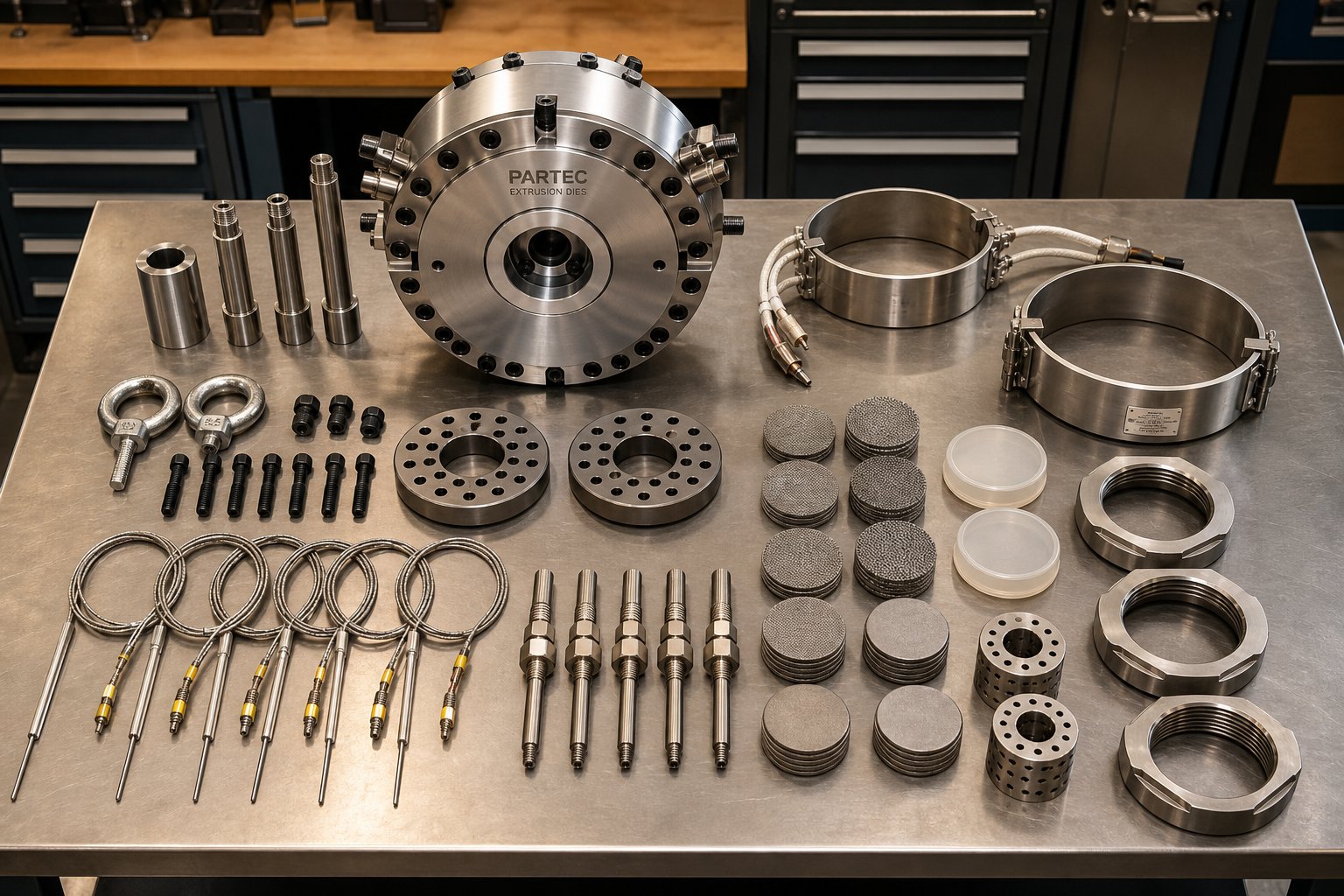
Suppliers like NANHAIYA exemplify this custom-manufacturing approach, offering die heads and associated extruder spare parts built from customer-supplied drawings, samples, photos, or measured dimensions. Their catalog extends beyond die heads to include screw tips, check rings, heater bands, thermocouples, screen packs, filter adapters, and pelletizing blades, covering the full range of components that maintenance teams typically need to source alongside die replacements.
Working with Suppliers on Custom Specifications
When you're replacing a die head, you're rarely replacing just one component. The die operates within a system, and wear or failure in the die head often coincides with degradation in adjacent parts that share the same thermal and mechanical stresses. Experienced maintenance engineers use every die head replacement as an opportunity to inspect and, if necessary, replace the surrounding components simultaneously.
Components that commonly need attention during a die head replacement include:
- Screen packs and filter adapters - These sit upstream of the die head and filter contaminants from the melt stream. Clogged or damaged screens increase back pressure and alter the flow distribution the die was designed to produce. Worn filter adapter seats allow bypass flow that defeats the purpose of filtration entirely.
- Heater bands - The bands clamped around the die head and adapter zones maintain precise melt temperature. A failed or degraded heater band creates a cold spot that changes local melt viscosity, distorting the flow profile through the die. Replacing heater bands proactively during a scheduled die head swap avoids an unplanned shutdown two weeks later.
- Thermocouples - Temperature sensors embedded in the die body and barrel provide the feedback that your controller relies on to regulate heating zones. A thermocouple that reads 10 degrees low causes the controller to overheat that zone, potentially degrading the polymer or shortening die life. Calibration drift is invisible until you check, so replacement on a fixed schedule is prudent.
- Breaker plates and adapter rings - These structural components support the screen pack and connect the barrel to the die head. Erosion, corrosion, or fatigue cracking in these parts compromises the seal integrity of the entire assembly, leading to melt leaks that damage equipment and create safety hazards.
Bundling these replacements into a single sourcing event reduces procurement overhead, ensures dimensional compatibility across the assembly, and minimizes the number of times you need to pull the line down for maintenance.
Not every supplier can handle the full scope of what a die head replacement demands. Before committing to a vendor, especially for custom-manufactured components, evaluate them against these criteria:
- Ability to work from multiple reference formats - Can the supplier produce accurate parts from engineering drawings, physical samples, photographs, or hand-measured dimensions? The more formats they accept, the more practical they are for real-world maintenance scenarios where documentation is incomplete.
- Material certification - Does the supplier provide full material traceability, including mill certificates for the tool steel used? For critical components like die heads that operate under sustained pressure and thermal cycling, knowing exactly what grade of steel you're getting isn't optional.
- Dimensional inspection reporting - A reputable supplier delivers each component with an inspection report documenting critical dimensions against the specified tolerances. This report serves as your incoming quality verification and becomes part of the die's maintenance history. Without it, you're trusting blindly that the part meets spec.
- Lead time reliability - A quoted lead time means nothing if the supplier consistently misses delivery dates. Ask for references, check track records, and build contingency into your production planning. Industry best practices for supplier evaluation recommend verifying delivery performance with existing customers before placing critical orders.
- Technical communication capability - Can the supplier engage in meaningful technical dialogue about material selection, heat treatment specifications, coating options, and dimensional trade-offs? A vendor that simply takes your order without asking questions about operating conditions or material compatibility is a vendor that may deliver a part that doesn't survive its first production run.
One overlooked sourcing strategy consistently saves both time and money: building a qualified supplier network before you need it. Waiting until a die head fails catastrophically to start searching for a replacement supplier puts you at the mercy of whoever can deliver fastest, not necessarily whoever can deliver best. Proactive maintenance teams identify and qualify at least two or three suppliers for their critical die components, establish pricing agreements, and keep updated dimensional records on file so that reorders can be placed with minimal delay.
The same principle applies to maintaining a small inventory of wear-prone spares, screen packs, heater bands, thermocouples, and breaker plates that degrade on predictable schedules. Stocking these items eliminates the lead time entirely for the most frequent replacements, keeping your extrusion line running while custom die head manufacturing proceeds on its normal timeline.
Whether you're sourcing from an OEM like Nordson Extrusion Dies Industries, a specialized aluminum die maker like Exco, or a custom parts manufacturer like NANHAIYA that builds from your samples and drawings, the fundamentals remain the same: verify material quality, confirm dimensional accuracy, demand documentation, and plan ahead. Your extrusion die is only as reliable as the supply chain that keeps it, and every component around it, in specification and ready to run.
Frequently Asked Questions About Extrusion Dies
1. What is an extrusion die and what does it do?
An extrusion die is a precision-machined steel tool featuring a shaped opening that defines the cross-sectional profile of material forced through it. Whether processing aluminum billets or molten polymer, the die converts raw material into continuous lengths with consistent geometry. The die opening's exact shape, combined with internal flow channels, bearing surfaces, and approach angles, controls the product's dimensions, wall thickness, and surface quality. Dies range from simple flat-sheet configurations to complex multi-hollow profile tools, and they operate within a broader assembly that includes backers, bolsters, and feeder plates for structural support.
2. How long does an extrusion die last before it needs replacement?
Die lifespan varies significantly between metal and polymer applications. Aluminum extrusion dies, made from H13 tool steel and operating under pressures exceeding 100,000 psi, typically last several hundred billets per service cycle before requiring bearing correction. With proper re-nitriding and periodic rework, a single die can go through multiple correction cycles before retirement. Polymer extrusion dies experience lower mechanical stress and can run for thousands to tens of thousands of operating hours with scheduled maintenance. Factors like surface coatings (nitriding, PVD, CVD), extruded material abrasiveness, and adherence to preventive maintenance routines all directly influence total service life.
3. What is the difference between a spider die and a spiral mandrel die?
Both produce hollow or tubular products, but they manage internal melt flow differently. A spider die supports its central mandrel with radial legs, which split the material stream and create visible weld lines where flows rejoin. These weld lines are mechanically weaker zones. A spiral mandrel die eliminates this problem by using helical channels machined into the mandrel that decrease in depth along the spiral path, forcing progressive mixing of the melt. This produces a nearly weld-free annular flow, making spiral mandrel dies the preferred choice for blown film and high-performance tubing where uniform hoop strength is critical.
4. Why is flow balancing so important in extrusion die design?
Flow balancing ensures every part of the material exits the die opening at the same velocity. Without it, faster-flowing sections cause the extrudate to warp, twist, or tear as it emerges. Engineers achieve balance by varying bearing lengths (longer bearings slow flow, shorter ones speed it up), optimizing entry angles, adding flow restrictors, and shaping channel geometry. In aluminum extrusion, bearing length differences of just a few millimeters across the die face correct significant velocity imbalances. Modern CFD simulation tools can test hundreds of geometry variations digitally, reducing reliance on costly physical trial-and-error correction runs.
5. Where can I source replacement extrusion die heads when original drawings are unavailable?
When OEM support has lapsed or documentation is missing, custom manufacturers offer the most flexible solution. Suppliers like NANHAIYA specialize in reverse-engineering worn or damaged die heads from physical samples, photographs, or hand-measured dimensions, producing replacements machined to the correct tool steel grade and tolerances. When evaluating any supplier, verify their ability to work from multiple reference formats, confirm material certification with mill certificates, request dimensional inspection reports for incoming quality verification, and check lead time reliability with existing customers. Building a qualified supplier network before emergencies arise saves significant downtime and cost.
Written by
Nanhaiya Technical Team
Zhoushan Nanhaiya Plastic Machinery Co., Ltd.
The Nanhaiya technical team supports screw and barrel manufacturing projects through application review, technical communication, custom manufacturing coordination, and production and quality control.
Discuss Your Application
Related Articles
More insights on screw barrel technology and plastics processing.

Extruder Machine Decoded: From Raw Pellet To Finished Product
Oct 6, 2026
Learn how an extruder machine works, compare single-screw vs. twin-screw types, and get expert guidance on specs, troubleshooting, and selection.
Read Article
PE Pipe Making Machine Decoded: From Raw Resin to Flawless Pipe
Oct 4, 2026
Learn how a PE pipe making machine works, from resin to finished pipe. Covers components, material grades, automation, troubleshooting, and buyer selection tips.
Read Article
PVC Profile Making Machine Decoded: From Raw Resin To Profit
Oct 3, 2026
Learn how a PVC profile making machine works — extrusion process steps, key technical parameters, die design, calibration methods, maintenance, and total cost of ownership.
Read ArticleLooking for something else?
Search by material, symptom or product and jump straight to the relevant page.
These are navigation suggestions based on keyword matching — not a quotation, not a delivery commitment, and not a substitute for engineering review. Final specification is confirmed by our engineers against your drawings and processed material.
Need help with screw barrel selection?
Share your machine model, processed material and application. Our team can help with pricing and technical support.