

What an Extrusion Barrel Does in Polymer Processing
Imagine a component that handles extreme temperatures, relentless mechanical stress, and corrosive chemical exposure — all while maintaining tolerances tight enough to control the quality of every inch of plastic product rolling off your line. That component is the extrusion barrel, and when it starts wearing out, everything downstream suffers.
What Is an Extrusion Barrel and Why Does It Matter
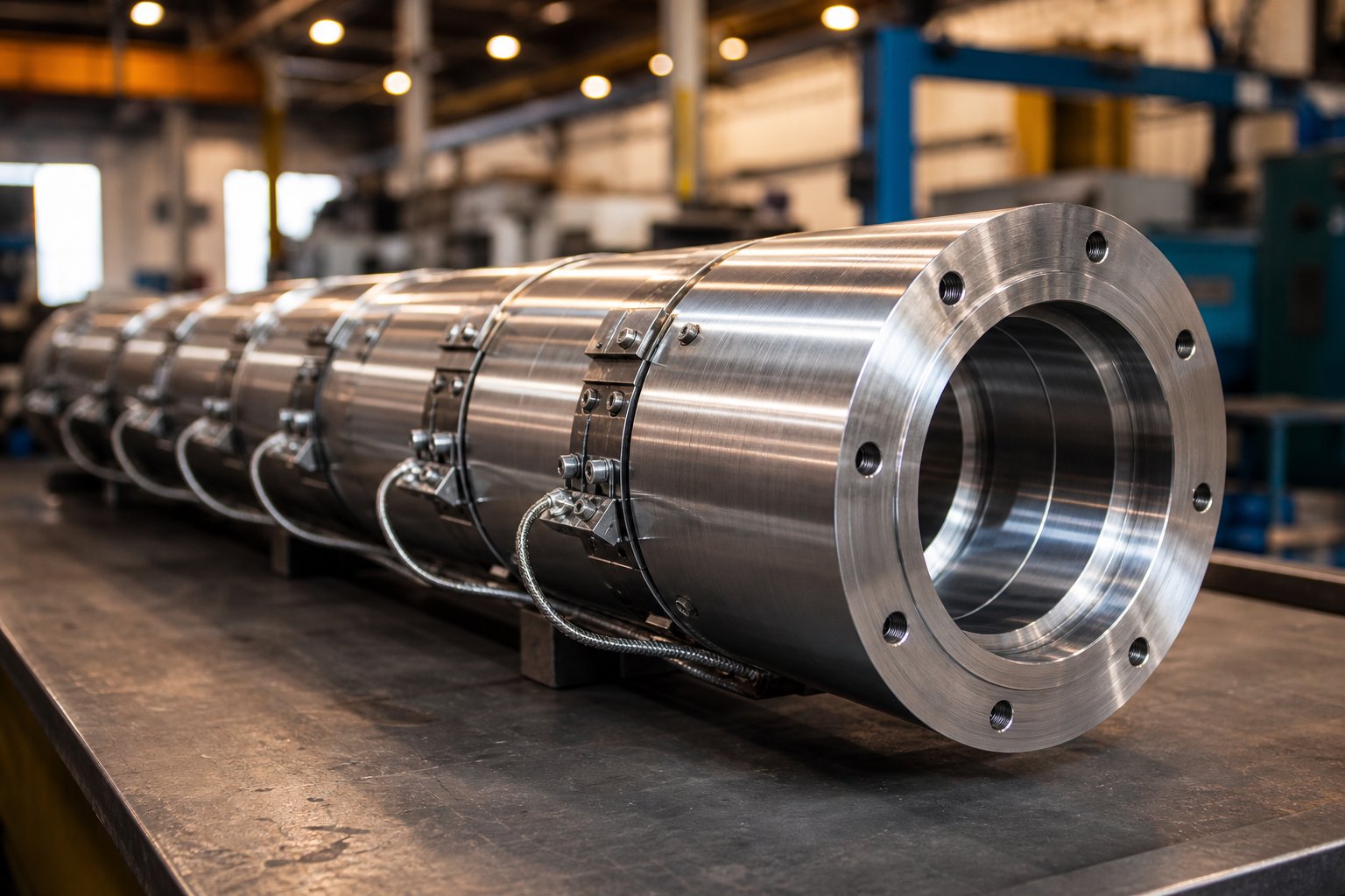
An extrusion barrel is a heated, precision-bored steel cylinder that houses the extruder screw and serves as the primary containment vessel for melting, mixing, compressing, and conveying polymer material from the feed throat to the die.
In simpler terms, think of it as the working chamber where raw plastic pellets transform into a uniform, pressurized melt ready for shaping. The barrel's inner bore, wall thickness, metallurgy, and thermal systems all work together to make that transformation happen consistently — hour after hour, shift after shift.
Why should you care about its condition? Because a worn or poorly specified extruder barrel directly erodes output quality, increases scrap rates, and quietly drives up energy costs long before a catastrophic failure shuts your line down. Bore diameter wear of just a few thousandths of an inch can reduce pressure stability, compromise melt homogeneity, and cut throughput by a meaningful percentage.
Core Functions of the Barrel in Polymer Processing
The barrel performs several interdependent roles during continuous extrusion. Each one influences the final product:
- Material intake — Plastic pellets enter the barrel through a feed throat opening near the hopper end. The geometry of this opening affects how consistently material flows into the extruder screw flights.
- Heat transfer — Heating elements along the barrel wall supply thermal energy that softens and melts the polymer. Cooling channels prevent overheating in zones where frictional shear generates excess heat.
- Compression and pressure generation — As the screw conveys material forward, the barrel's enclosed bore allows pressure to build progressively. This pressure is essential for pushing molten polymer through the die at a stable rate.
- Melt conditioning — The barrel and screw together control residence time, shear rate, and temperature uniformity, ensuring the melt reaches the die with consistent viscosity and composition.
These functions are tightly coupled. A barrel with corroded bore surfaces disrupts heat transfer. A worn bore increases the gap between the screw flight and barrel wall, reducing conveying efficiency and pressure control. Even the steel alloy selected during manufacturing shapes how long the barrel can perform each of these roles reliably.
That relationship between material choice and real-world performance is exactly where many processors make costly mistakes — selecting a barrel based on price alone, without considering whether its metallurgy matches the resin, the filler loading, or the thermal demands of the application. The sections ahead break down construction materials, feed throat innovations, thermal zone management, wear mechanisms, and a practical polymer-to-barrel matching guide designed to prevent exactly that kind of mismatch.
Barrel Construction Materials Compared
Selecting the right steel alloy or liner for your extruder screws and barrels is not a cosmetic decision — it determines how many operating hours you get before wear degrades output quality and forces a line shutdown. The barrel bore is the surface that endures constant contact with molten polymer, abrasive fillers, and corrosive off-gases, so its metallurgy has to match the abuse your process dishes out. Pick a material that falls short, and you'll be pulling the barrel far sooner than your maintenance budget anticipated.
Four primary material classes dominate modern screw barrel construction, each engineered for a different balance of hardness, heat tolerance, corrosion resistance, and cost. Here is how they compare side by side:
| Material Type | Typical Hardness | Max Operating Temp | Corrosion Resistance | Abrasion Resistance | Best Application | Relative Cost |
|---|---|---|---|---|---|---|
| Nitrided Steel (e.g., 38CrMoAlA) | 65 - 70 HRC surface | Moderate (standard extrusion temps) | Low to Moderate | Moderate | Clean, unfilled polymers (PP, PE, PS, ABS) | $ |
| Bimetallic Liner — Iron-Based (e.g., Fe+Ni+Cr+B alloys) | 58 - 62 HRC | Up to ~400 degC | Low to Moderate | High | Glass-filled and mineral-filled compounds | $$ |
| Bimetallic Liner — Nickel-Based (e.g., Ni+Cr+Co+B alloys) | 50 - 60 HRC | Up to ~450 degC | High | Moderate to High | PVC, corrosive or chemically aggressive resins | $$-$$$ |
| Bimetallic Liner — Tungsten Carbide (e.g., Ni+WC+Cr+B alloys) | 55 - 60 HRC | Up to ~600 degC | Moderate to High | Very High | Highly abrasive, high-temp engineering polymers | $$$ |
| Powder Metallurgy (PM/HIP) Liners | High (varies by composition) | High | High | Very High | Extreme-wear specialty compounds | $$$$ |
Nitrided Steel and Standard Barrel Construction
Nitriding diffuses nitrogen into the surface of an alloy steel barrel, forming a hardened case roughly 0.4 to 0.7 mm deep without adding a separate layer of different material. Common base steels include 38CrMoAlA, 34CrAlNi7, and 31CrMoV9, each chosen based on the machine platform and the duty cycle. Surface hardness reaches approximately 65 to 70 HRC — hard enough to handle the sliding contact of a rotating screw against a clean polymer melt.
For processing natural polyolefins like PE or PP, standard polystyrene, or unfilled ABS, a nitrided barrel delivers reliable service at the lowest cost tier. There is no technical reason to pay for a bimetallic upgrade when the resin carries no abrasive filler and produces no corrosive byproducts. The limitation, however, is clear: that thin hardened case wears through quickly once glass fiber, mineral reinforcement, or corrosive off-gases enter the picture. Below the case sits softer core steel that erodes rapidly, and at that point, replacement is inevitable.
Bimetallic and Advanced Liner Technologies
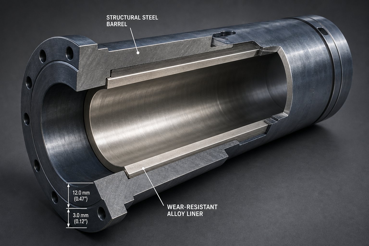
When the feedstock gets aggressive, bimetallic construction is the established countermeasure. The concept is straightforward — bond a wear-resistant alloy to the inner bore of the structural steel barrel, creating screws and barrels that combine the mechanical strength of the base material with a specialized working surface.
For barrels, the alloy is applied by centrifugal casting: molten alloy is spun inside the bore, forming a dense, uniform lining typically 2.0 to 3.0 mm thick. That thickness matters — it is several times deeper than a nitrided case, which is why bimetallic barrels can last three to five times longer than their nitrided counterparts in demanding environments.
The alloy chemistry drives everything. Iron-based linings (Fe+Ni+Cr+B) deliver strong abrasion resistance with hardness values in the 58 to 62 HRC range, making them a solid default for glass-filled nylons and mineral-loaded compounds where temperatures stay below roughly 400 degrees Celsius. Nickel-based alloys (Ni+Cr+Co+B) shift the balance toward corrosion resistance — exactly what PVC processors need, since degrading PVC releases hydrochloric acid that attacks iron-based surfaces. Alloys incorporating vanadium (Ni+Cr+Co+V+B) split the difference, balancing wear and corrosion for mixed-duty or uncertain feedstock scenarios.
Powder metallurgy (PM) and hot isostatic pressing (HIP) liners represent the premium tier. These liners are manufactured from fine metal powders fused under high pressure and temperature, producing an exceptionally uniform microstructure with superior wear and corrosion properties. They are typically reserved for specialty applications where conventional bimetallic linings still fall short — think highly filled engineering compounds processed at elevated temperatures on tight-tolerance lines.
Tungsten Carbide and Ceramic Coating Options
For the most punishing applications — heavily mineral-loaded masterbatches, recycled feed contaminated with grit and metal fines, or high-temperature engineering polymers — tungsten carbide linings stand at the top of the performance ladder. These alloys embed hard tungsten carbide particles within a nickel-chromium matrix. The embedded carbides do the heavy lifting against abrasive fillers, which is why a tungsten carbide liner can outperform a harder-by-the-numbers iron-based lining in real-world abrasion resistance. Bulk hardness readings of 55 to 60 HRC do not tell the full story; the carbide particles themselves are far harder, and they are what the abrasive particles actually encounter.
Ceramic linings and coatings offer an alternative path for extreme environments. Ceramic bore treatments provide outstanding chemical inertness and thermal stability, resisting both corrosion and abrasion simultaneously. They are less common than metallic bimetallic liners due to higher cost and more complex application processes, but they earn their place in fluoropolymer processing and other applications involving highly reactive chemistries where even nickel-based alloys face accelerated degradation.
The takeaway for any processor evaluating a screw barrel replacement? Start with the feedstock. The resin type, filler content, and processing temperature dictate which material class will deliver the best total cost of ownership — and that calculation extends well beyond the purchase price. A barrel that costs twice as much upfront but runs three to five times longer almost always wins the math on a per-hour-of-production basis.
Material selection, though, is only half the equation. The same barrel metallurgy performs very differently in an extrusion application versus an injection molding environment, thanks to fundamental differences in how each process loads the barrel mechanically and thermally.
Extrusion Barrels vs. Injection Molding Barrels
Both barrel types house a rotating screw inside a heated bore — so why can't you just swap one for the other? The answer lies in how each process loads the barrel. Extrusion is a continuous, steady-state operation. Injection molding is cyclical and shot-based, with the screw alternating between plasticizing (rotating) and injecting (reciprocating axially like a plunger). That fundamental operational difference ripples through every aspect of barrel engineering, from wall thickness and length to pressure demands and wear behavior.
Engineering Differences Between Extrusion and Injection Barrels
An extruder screw and barrel assembly is built for endurance. The barrel runs long — typical length-to-diameter (L/D) ratios of 24:1 to 36:1 — because the screw needs enough residence time to fully melt, mix, and pressurize polymer in a single continuous pass. The discharge end connects to a die adapter that shapes molten plastic into a profile, sheet, or pipe. Operating pressures generally fall in the 100 to 400 bar range, sustained constantly throughout production.
An injection molding barrel and screw assembly faces a very different duty cycle. L/D ratios are shorter — commonly 18:1 to 24:1 — because the screw only needs to plasticize a discrete shot volume before pushing it into the mold. But the pressure spikes are far more severe: injection pressures reach 500 to 2,000 bar during each shot. That is why injection barrels use thicker walls to handle the repeated clamp forces and high-pressure injection cycles. The discharge end terminates in a nozzle with a check valve (non-return valve) that prevents backflow during injection — components that have no counterpart in extrusion.
These structural differences mean the two barrel types are not interchangeable, even when bore diameters match. Injection molding screws and barrels endure thousands of pressure cycles per shift, concentrating fatigue stress near the nozzle end and check valve seat. Extrusion barrels, by contrast, experience constant but lower pressure across a much longer bore, spreading wear more evenly but over a greater surface area.
| Dimension | Extrusion Barrel | Injection Molding Barrel |
|---|---|---|
| Operation Mode | Continuous rotation | Cyclic: rotate to plasticize, then reciprocate to inject |
| Typical L/D Ratio | 24:1 to 36:1 | 18:1 to 24:1 |
| Pressure Profile | 100 - 400 bar, sustained | 500 - 2,000 bar, intermittent spikes |
| End Configuration | Die adapter / breaker plate | Nozzle with check valve (non-return valve) |
| Wall Thickness | Thinner (longer barrel, lower pressure) | Thicker (shorter barrel, high cyclic pressure) |
| Common Liner Materials | Nitrided, bimetallic (iron- or nickel-based), tungsten carbide | Nitrided, bimetallic, tool steel inserts |
| Primary Wear Zone | Transition zone and metering zone (distributed) | Feed zone and check valve area (concentrated) |
How Application Type Affects Barrel Specification
These engineering differences directly shape how you specify replacement barrels and plan maintenance intervals. Extrusion barrels run continuously for weeks or months, so wear accumulates gradually across long bore lengths. Resleeving an extruder barrel along its full length is often more expensive than purchasing a new one due to the sheer length involved. Injection molding screws, however, tend to wear in concentrated zones — particularly the feed section and the check valve seat — making localized resleeving a cost-effective repair option.
Liner selection also shifts. Injection barrels benefit from extremely hard bore surfaces near the nozzle end to resist the repeated pressure spikes, while extrusion applications prioritize consistent abrasion and corrosion resistance across the full barrel length. If you are running glass-filled nylons through an injection machine, a bimetallic liner concentrated in the high-wear zones may suffice. The same resin in an extrusion line demands bimetallic protection along the entire bore.
Understanding which type of barrel you are specifying — and which wear patterns to expect — keeps you from applying injection molding assumptions to an extrusion problem, or vice versa. The next layer of that specification puzzle involves how raw material actually enters the barrel: feed throat design and the emerging role of grooved feed technology.
Feed Throat Design and Grooved Feed Technology
Every pellet that your single extruder screw ever touches must first pass through the feed throat. Yet this component rarely gets the engineering attention it deserves. Many operators view it as nothing more than a hole that connects the hopper to the bore. In reality, the feed throat is the initial section of the extruder feed barrel — and its design has a measurable impact on conveying efficiency, output stability, and ultimately barrel wear downstream.
Two fundamentally different approaches exist: smooth-bore feed sections and grooved feed designs. Choosing between them is not a matter of preference — it depends on the resin family, regrind strategy, and throughput target driving your operation.
Smooth Bore vs. Grooved Feed Barrel Design
In a smooth-bore barrel extruder, the internal bore surface at the feed section is polished and uninterrupted, identical to the bore further downstream. Solids conveying relies entirely on the frictional difference between the polymer and the barrel wall versus the polymer and the screw root. When barrel-to-polymer friction exceeds screw-to-polymer friction, pellets move forward. When that friction balance tips the wrong way — picture slippery polyolefin pellets against a cool steel surface — output drops and surging begins.
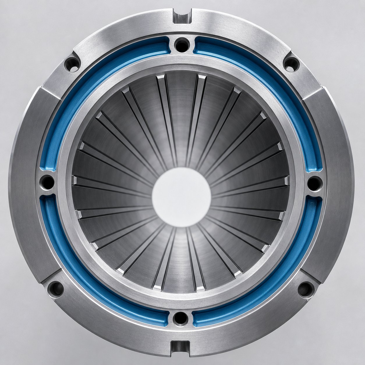
Grooved feed technology changes the physics. Longitudinal grooves machined into the feed bore — typically 8 to 18 per barrel, depending on diameter and resin viscosity — physically lock incoming pellets against the barrel wall. This prevents pellet rotation, forcing material forward with a mechanical grip rather than relying on friction alone. The result, as documented by decades of European processing experience, is 20 to 40% higher output per RPM compared to the same diameter machine with a smooth feed bore.
Groove dimensions are tightly engineered. On a 3.5-inch extruder, individual grooves are typically 0.15 to 0.3 inches wide, with a starting depth of 0.12 to 0.37 inches that tapers to zero within three to four diameters past the feed opening. They run parallel to the screw axis, although some older designs experimented with helical orientations before the industry largely settled on axial configurations. Higher-viscosity resins like HMW-HDPE and polypropylene generally benefit from more grooves, while lower-viscosity materials perform better with fewer.
Feed throat geometry also matters at the point where pellets first enter the bore. A radial entry — where pellets drop straight down through the feed opening — is the most common configuration. Tangential entry designs, where the opening is offset to introduce material at an angle aligned with screw rotation, can improve intake consistency for certain pellet shapes and bulk densities. The right geometry depends on how uniformly your feedstock flows from the hopper and whether you are blending virgin pellets with regrind of varying particle size.
Water-Cooled Feed Throats and Solids Conveying
Whether smooth or grooved, feed throats need active temperature management. Here is why: if the barrel wall in the feed zone gets too hot, pellets begin softening or even melting before they are fully conveyed into the compression section. Premature melting sounds harmless — the resin has to melt eventually, right? — but it actually kills conveying efficiency. A partially melted pellet smears against the bore surface, collapsing the frictional transport mechanism that pushes solids forward. In grooved designs, soft pellets fill and plug the grooves, destroying their mechanical grip entirely.
That is why virtually every extruder uses a water-cooled feed throat. The throat is cored with internal channels so that coolant can circulate through the metal surrounding the feed opening. For grooved feed barrels, cooling is even more critical — intensive water flow surrounds both the feed opening and the extended grooved section to keep pellets solid and free-flowing throughout the grooved zone.
However, excessive cooling is just as problematic as insufficient cooling. Industry testing has shown that overly cold feed throats reduce the barrel-to-polymer frictional drag that drives forward conveying, lowering specific output by 10 to 20% depending on the polymer. Each extruder has an optimal feed throat temperature — a sweet spot that maintains pellet integrity while maximizing the friction needed for efficient transport. Finding it requires trial-and-error adjustment while monitoring specific output and head pressure stability, and adding a dedicated thermocouple in the feed throat makes repeating that sweet spot far easier across product changeovers.
For processors running high-melt-temperature polymers like nylon, PET, or polycarbonate on grooved-feed equipment, the approach actually reverses: heat is applied to the grooves — typically 200 to 300 degrees Fahrenheit or higher — to intentionally soften the resin and reduce feeding efficiency. This prevents dangerous pressure buildup at the end of the grooved section, where pressures can spike to 15,000 to 20,000 psi with aggressive feeding.
Grooved feed technology delivers clear performance advantages, but those gains come with engineering trade-offs that your maintenance team and capital budget need to account for:
Advantages of Grooved Feed Designs
- Higher throughput per RPM — Mechanical pellet locking increases solids conveying efficiency, enabling 20 to 40% more output at a given screw speed compared to smooth bore.
- Lower melt temperatures — Because the barrel extruder reaches target output at reduced RPM, less frictional shear energy enters the melt, yielding cooler discharge temperatures.
- Improved pressure generation — Grooved feeding is less sensitive to die back-pressure, making output more stable when processing through restrictive dies or screens.
- Reduced energy consumption — Davis-Standard case studies on HDPE pipe processing documented annual energy savings of 268,000 to 388,000 kW-hr per extruder compared to larger-diameter smooth-bore alternatives.
- Smaller machine footprint — A smaller-diameter grooved feed extruder can match or exceed the output of a larger smooth-bore machine, saving floor space and reducing capital cost.
Limitations of Grooved Feed Designs
- Accelerated wear in the grooved zone — Long grooves must be hardened by nitriding or tungsten carbide coating to resist abrasion; even then, sleeve replacement every 5 to 10 years is typical.
- Higher drive power and torque requirements — Greater solids-conveying force demands a larger gearbox and more startup torque, increasing drive train cost.
- Limited resin versatility — Grooved feeds perform best with dedicated polyolefin operations. Soft elastomers, high-melt-temperature polymers, and processes with variable regrind percentages or particle sizes can cause feeding inconsistency or dangerous pressure spikes.
- Not ideal for vented extrusion — An aggressively efficient first stage can overwhelm the second-stage pumping capacity, flooding vent ports and compromising degassing.
- More disciplined operation required — Particle size, regrind percentage, and color masterbatch loading all need tighter control than with smooth-bore feeding.
The bottom line? Grooved feed technology is a proven performance multiplier for dedicated polyolefin lines running at high output rates. But it demands a barrel and screw system engineered specifically for the application — from groove hardening and cooling jacket capacity to screw channel depth and gearbox sizing.
Feed throat design determines how efficiently raw material enters the barrel. What happens to that material after it enters — how heat is applied, regulated, and balanced across the barrel's length — is an entirely separate engineering challenge, one that many processors underestimate until melt quality problems start appearing at the die.
Heating and Cooling Zone Configuration
Getting material into the barrel is only the starting line. The real performance question is how thermal energy is delivered, distributed, and regulated along the barrel's length as the extrusion screw drives polymer from solid pellets to a uniform melt. Every degree of temperature variation ripples forward into melt viscosity, dimensional stability, and surface quality at the die — yet surprisingly few processors fully understand how their barrel's thermal zones actually work together.
How Barrel Heating Zones Shape Melt Quality
A screw extruder barrel is not heated as a single unit. It is divided into discrete thermal zones — typically four to eight, depending on barrel length and L/D ratio — each equipped with its own heater band and cooling provision. This zone-by-zone architecture exists because polymer does not need the same temperature at every point along its journey. Feed-end temperatures must stay low enough to preserve solids conveying. Transition-zone temperatures need to climb aggressively to initiate melting. Metering-zone temperatures must stabilize to deliver a homogeneous melt at consistent viscosity.
Three heater band technologies dominate the field, and each brings a different balance of cost, thermal response, and durability:
- Mica band heaters — The most common and economical option. Mica bands use resistive heating elements insulated with mica sheets, delivering high thermal conductivity and energy-efficient heat transfer. They clamp around the barrel exterior and perform well up to approximately 450 degrees Celsius. Their limitation is relatively modest watt density, which can become a bottleneck on high-output lines running heat-demanding resins.
- Ceramic band heaters — These use interlocking ceramic tiles as insulation, achieving higher watt densities and better energy retention than mica bands. Ceramic heaters reduce heat loss to the surrounding environment, lowering energy consumption by an estimated 10 to 30% compared to mica in many installations. They tolerate higher surface temperatures and are a strong choice for screw extrusion lines where energy efficiency and precise control are priorities.
- Cast-aluminum heaters — Custom-cast to match the barrel profile, these heaters provide excellent thermal contact and uniform heat distribution. They are the premium option for applications demanding tight temperature uniformity across large barrel diameters or unusual geometries.
On the cooling side, each zone also needs the ability to shed heat — not just add it. Frictional shear generated by the rotating screw can push zone temperatures above setpoint, especially in the transition and metering sections where melt viscosity creates significant resistance. Air-cooled blowers are the simplest cooling approach: fans or blowers direct ambient air across the barrel surface between heater bands. For applications requiring faster or more precise cooling response, liquid-cooled channels — bored directly into the barrel wall or integrated into cast cooling jackets — circulate water or oil to pull heat more aggressively.
The typical zone layout in a single-screw extruder follows a logical progression from feed to discharge:
- Feed zone (Zone 1) — Set to the lowest temperature, often barely above ambient or moderately warm. The goal is to maintain solid pellet integrity and maximize conveying friction. Water cooling from the feed throat usually overlaps this zone.
- Transition zone (Zones 2-3) — Temperatures ramp upward here, initiating melting as the screw channel depth decreases and compression begins. This is where the extrusion barrel does its heaviest thermal lifting.
- Metering zone (Zones 4-5 or beyond) — Temperatures level off or increase slightly. The polymer should be fully melted, and these zones focus on homogenizing melt temperature and viscosity before it reaches the die adapter.
- Die adapter and die zones — Often treated as separate control zones. Temperatures here fine-tune melt viscosity for uniform flow distribution through the die lips.
The number of zones matters. Too few zones and you lose the ability to create the gradual, controlled temperature ramp that prevents thermal shock and ensures complete melting. Too many zones add controller complexity and cost without proportional benefit. Most general-purpose single-screw lines run five to seven barrel zones plus one or two die zones — enough granularity to manage the thermal profile without overwhelming your operators.
Segmented Barrel Designs and Zone Replacement
Here is a practical question worth asking: when a single zone of your barrel wears out or suffers corrosion damage, do you want to replace the entire barrel? On a monolithic one-piece barrel, you have no choice. On a segmented barrel, you do.
Segmented barrels are built from individual cylindrical sections bolted together end-to-end, with each segment corresponding to one or more thermal zones. Twin screw extruders have used segmented barrels for decades — the modular design allows processors to rearrange sections for different screw configurations, swap in vented segments, or replace a single worn section without scrapping the entire assembly. Single-screw platforms increasingly offer segmented options as well, particularly on larger machines where full barrel replacement costs can run into six figures.
The advantages go beyond replacement economics. Segmented construction lets you mix liner materials along the barrel length. Imagine running a corrosive resin that attacks the first few zones most aggressively — you can install nickel-alloy-lined segments in those positions while using standard nitrided segments downstream where conditions are less severe. This targeted approach optimizes both performance and cost.
The trade-off? Every joint between segments is a potential leak point under high melt pressure, and misalignment during assembly can create bore steps that disrupt flow and accelerate wear. Precision machining and proper torquing of flange bolts are non-negotiable. When executed well, though, segmented designs deliver flexibility that monolithic barrels simply cannot match.
PID Temperature Control and Energy Efficiency
Even the best heater bands and segmented barrels cannot deliver stable melt quality without intelligent control. PID (proportional-integral-derivative) controllers are the standard technology for managing each thermal zone independently. You set a target temperature, the controller reads the actual temperature via a thermocouple or RTD sensor embedded in the barrel wall, and it continuously adjusts heater output — and cooling activation — to hold the zone at setpoint.
The "PID" part refers to three mathematical terms the controller uses to calculate corrections. The proportional term responds to how far the current temperature is from the target. The integral term accounts for accumulated error over time, eliminating persistent offset. The derivative term anticipates where the temperature is heading based on its rate of change, dampening overshoot. Together, these three terms keep each zone within a tolerance as tight as plus or minus 2 degrees Celsius when properly tuned — critical for heat-sensitive polymers like PETG or polycarbonate where even small temperature excursions cause haze, bubbles, or degradation.
Sensor placement directly affects control accuracy. Thermocouples positioned too deep in the barrel wall read closer to the heater band temperature than the actual melt-contact surface temperature. Sensors placed too shallow risk mechanical damage. Most barrel manufacturers specify thermocouple well depth and position for each zone, and following those specifications is essential for meaningful readings.
Three thermal troubleshooting scenarios come up repeatedly on screw extruder production floors, and recognizing them quickly can save hours of downtime:
- Zone overheating despite heaters being off — This almost always indicates shear-generated heat from the extrusion screw exceeding the cooling system's capacity. You will see the controller calling for maximum cooling while the actual temperature stays above setpoint. Solutions include reducing screw speed, increasing cooling airflow or switching to liquid cooling, or checking whether screw wear has reduced channel depth and increased shear intensity.
- Underpowered heater bands — A zone that cannot reach setpoint during startup, or slowly drifts below target during production, suggests heater bands that are undersized for the thermal load, partially burned out, or making poor contact with the barrel surface due to loose clamps or warped elements. Measuring actual wattage draw against rated wattage quickly identifies failed elements.
- Cooling zone malfunction — If a fan fails or a coolant line clogs in one zone, that zone runs hot and disrupts the entire thermal profile. The downstream zone's controller tries to compensate, creating a cascading temperature imbalance. Regular inspection of blower motors, coolant flow rates, and solenoid valves prevents these silent failures from becoming quality crises.
The interplay between heating, cooling, and control is what transforms a raw steel cylinder into a precision processing tool. But even the most perfectly tuned thermal profile cannot overcome a barrel that is being destroyed from the inside. Abrasive fillers grinding away at the bore, corrosive byproducts etching the liner surface, or erosive melt turbulence carving channels through the metal — these wear mechanisms operate silently beneath your heater bands, steadily undermining the very bore surface that your thermal system depends on.
Wear Mechanisms and Barrel Protection Strategies
Four distinct wear mechanisms attack extrusion barrels from the inside, and each one leaves a different fingerprint on the bore surface. Identifying which mechanism is active in your process is the single most important step toward selecting the right barrel material — because a liner that excels against abrasion can fail rapidly under corrosive attack, and vice versa. Yet most processors never inspect closely enough to distinguish one from another until output quality has already degraded.
Here is the complete picture: each wear mechanism mapped to its root cause, the polymers and additives most likely to trigger it, the barrel zones where damage concentrates, and the material or coating that fights back most effectively.
| Wear Mechanism | Root Cause | Trigger Materials | Most Vulnerable Zones | Recommended Barrel Material / Coating |
|---|---|---|---|---|
| Abrasive | Hard particles scraping and eroding the bore surface through direct mechanical contact | Glass fiber, mineral fillers (CaCO3, talc, wollastonite), metal flakes, recycled regrind with contaminants | Transition zone and metering zone, where pressure compresses filler particles against the bore wall | Tungsten carbide bimetallic liner; HVOF coating for extreme loading; iron-based bimetallic (Fe+Ni+Cr+B) for moderate filler levels |
| Adhesive | Metal-to-metal contact between screw flight OD and barrel bore, causing material transfer and scoring | Any polymer — mechanism is driven by mechanical conditions (screw deflection, insufficient melt lubrication) rather than resin chemistry | Feed zone (before full melt lubrication develops); twin screw barrel intermeshing zone; areas of excessive screw deflection | Bimetallic liner with high surface hardness; proper screw-to-barrel clearance specification; controlled shutdown procedures to avoid dry running |
| Corrosive | Chemical attack on the bore surface by acidic or reactive byproducts released during polymer degradation | PVC and CPVC (release HCl); fluoropolymers (release HF); flame-retardant additives (halogenated compounds); acetals (release formaldehyde) | Metering zone and die adapter (highest melt temperatures accelerate degradation); any zone where material stagnates | Nickel-based bimetallic liner (Ni+Cr+Co+B); ceramic linings for fluoropolymers; stainless steel bore inserts for mild corrosive exposure |
| Erosive | High-velocity melt flow impinging on bore surfaces at points of flow redirection or turbulence | Low-viscosity melts at high screw speeds; any resin processed at elevated throughput with abrasive particulate suspended in the melt stream | Vent port openings; die adapter transitions; areas immediately downstream of mixing elements or screen packs | Tungsten carbide or nickel-based bimetallic liner; hardened vent port inserts; streamlined flow-path geometry to reduce turbulence |
Abrasive and Corrosive Wear in Extrusion Barrels
Abrasive wear is the most common destroyer of extruder barrels. Every glass fiber, every grain of calcium carbonate, every particle of talc acts like microscopic sandpaper scraping against the bore wall as the screw pushes material forward. The result? Sharp machined edges on screw flights become rounded, smooth, and occasionally polished, while the barrel bore gradually enlarges. The rate of damage depends on three factors: the hardness and angularity of the filler particles, the screw speed and throughput rate, and the barrel's own surface hardness.
You will notice that abrasion is production-volume dependent rather than time dependent. A barrel sitting idle does not wear. A barrel processing 500 kg/hr of 40% glass-filled nylon wears dramatically faster than the same barrel running unfilled polypropylene at the same rate. This makes abrasion uniquely difficult to predict unless you track cumulative throughput of abrasive formulations against bore diameter measurements — a practice surprisingly few plants maintain.
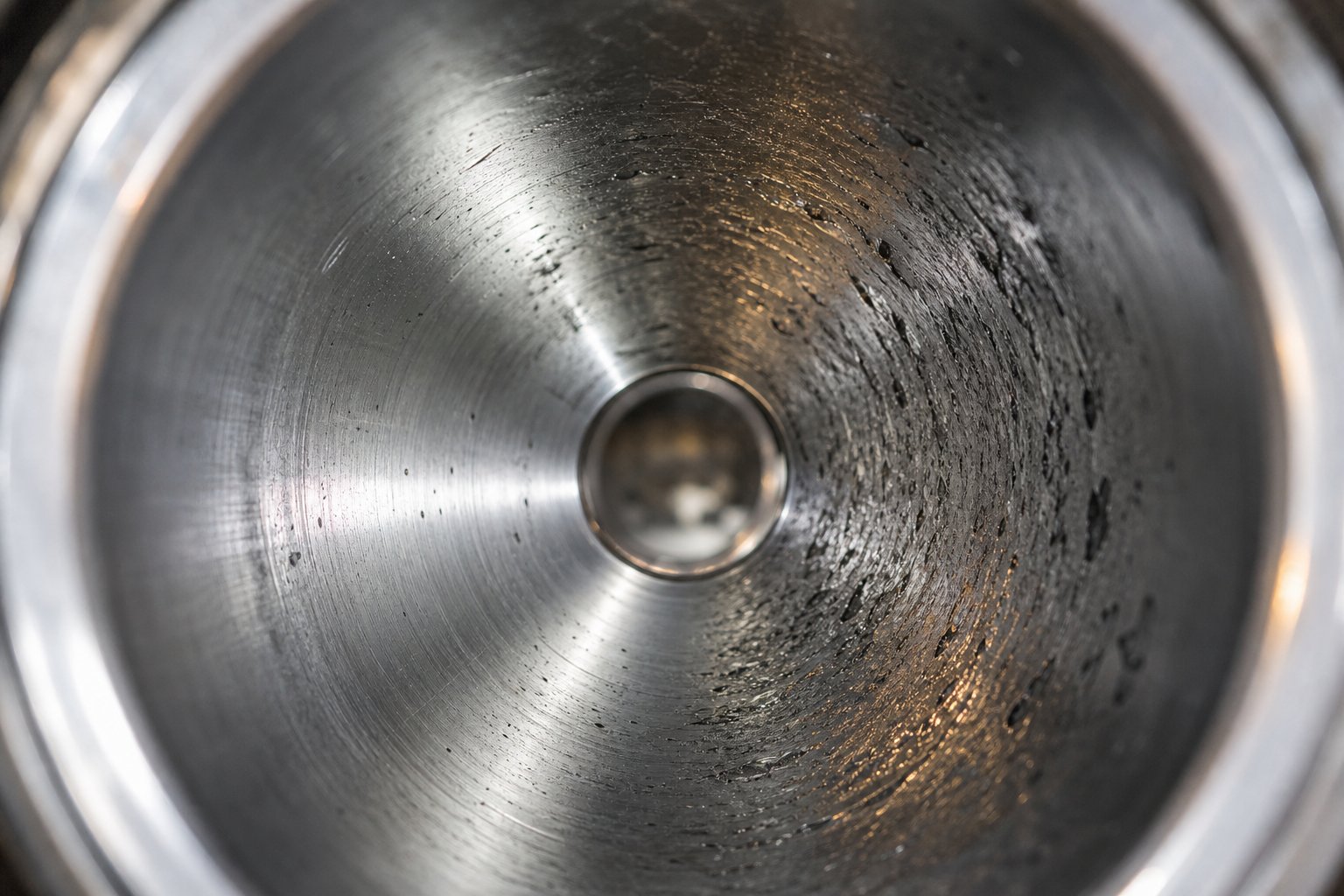
Corrosive wear operates on a completely different principle. Instead of mechanical grinding, it involves chemical reactions between the bore surface and aggressive byproducts released by the polymer during thermal processing. PVC is the most notorious offender: as it degrades, it releases hydrochloric acid (HCl) that attacks iron-based barrel materials from the inside. The bore surface develops a dimpled or pitted appearance — distinctly different from the smooth, polished look of abrasive wear. Fluoropolymers release hydrofluoric acid (HF), which is even more aggressive. Halogenated flame retardants and certain colorant chemistries add their own corrosive contributions.
The danger of corrosive wear is that it accelerates over time. Pitting creates crevices where degraded polymer stagnates, generating more acid, which deepens the pits further. A nitrided barrel processing PVC can lose its thin hardened case within 6 to 18 months, exposing the soft core steel underneath — at which point bore wear accelerates dramatically and replacement becomes urgent.
Adhesive wear adds a third dimension. When the extruder screw shaft deflects and the flight tips contact the bore wall directly — metal on metal, without a lubricating film of molten polymer — material transfers between surfaces. In twin screw and barrel systems, this can happen when screws rotate at high speed between production runs without polymer present. Screw flights flatten at the outer diameter while score marks appear on the barrel wall. Controlled shutdown procedures — automatically reducing screw speed when torque drops below a threshold — are the most effective prevention. Some twin screw barrel platforms include automatic idle-down features that slow the machine to roughly 100 RPM when the feed stops, preventing dry metal-to-metal contact.
Erosive wear is subtler. It occurs where high-velocity melt changes direction suddenly — at vent port openings, transitions into die adapters, or immediately downstream of restrictive mixing elements. The melt acts as a carrier for suspended abrasive particles, and the energy of redirection concentrates their impact on small areas of the bore. Erosive damage often goes unnoticed because it occurs in locations that are difficult to inspect visually without pulling the screw. Hardened vent port inserts and careful attention to flow-path geometry at transition points help mitigate the damage.
In practice, most extrusion barrels experience a combination of these mechanisms simultaneously. Glass-filled PVC, for example, delivers both abrasive and corrosive attack — and the two work synergistically. Corrosion roughens the bore surface, creating anchor points where abrasive particles dig in more effectively. A nickel-based bimetallic liner resists the corrosion, but if the filler loading is high, a tungsten carbide-reinforced variant provides the combined defense these conditions demand.
Bore Finishing and Surface Roughness Standards
Barrel metallurgy gets most of the attention during specification, but the bore's surface finish plays a quieter — and equally consequential — role in both processing performance and wear resistance. A bore that is too rough creates drag, increases shear heating, and provides microscopic ledges where degraded polymer accumulates. A bore that is too smooth can actually reduce conveying efficiency in the feed zone, where some frictional grip on the polymer is necessary.
After a barrel bore is machined to its nominal diameter, it undergoes honing — a precision finishing process that uses abrasive stones to achieve a controlled surface texture. The target measurement is surface roughness, expressed as Ra (arithmetic average roughness). Industry standards for extrusion barrels typically specify a bore surface roughness of Ra less than 0.4 micrometers after honing. For high-precision applications — medical tubing, optical-grade film, food packaging — tighter specifications of Ra 0.2 micrometers or below are common.
Why does this matter for wear? A poorly honed bore with inconsistent roughness creates localized high spots where the screw flight makes preferential contact. These high spots wear faster, generating metal debris that acts as an additional abrasive in the melt. As the high spots erode, the bore develops an uneven profile that compounds conveying instability and pressure fluctuations. Proper honing eliminates these irregularities and establishes a uniform surface that distributes screw contact evenly across the bore.
Bore roundness is equally critical. The internal diameter should hold concentricity within tight limits — quality manufacturers hold bore roundness to 0.015 mm or less. Any out-of-round condition creates a variable clearance gap between the screw flight and bore wall. The thin side of that gap experiences accelerated adhesive wear, while the thick side allows excessive melt leakage (back-flow) that reduces output efficiency. During barrel inspections, checking both bore diameter and roundness at multiple axial positions gives a far more accurate picture of barrel condition than a single diameter reading alone.
For bimetallic extrusion barrels, honing must penetrate the alloy liner without breaching it. Since centrifugally cast liners are typically 1.5 to 3.0 mm thick, aggressive honing that removes too much material reduces the effective wear-resistant layer and shortens service life. Experienced barrel manufacturers control honing stock removal to leave the maximum possible liner thickness while still achieving the specified surface roughness — a balance that requires careful process control and inspection at each stage.
Barrel Venting and Degassing Configurations
Not every molecule that enters the barrel belongs in the final product. Moisture, trapped air, residual monomers, volatile additives, and degradation byproducts all need an exit path — and that path is the barrel vent. Without effective venting, these volatiles remain trapped in the melt and emerge as voids, bubbles, surface defects, and compromised mechanical properties in the finished part.
Two venting approaches serve different purposes. Atmospheric vents are open ports in the barrel wall that allow gases to escape at ambient pressure. They are positioned in zones where the screw design creates a low degree of fill — meaning the screw channels are not completely full of polymer, giving gases room to migrate to the vent opening. Most twin-screw compounding extruders use one or more atmospheric vents for removing entrained air, particularly at side feeder locations where powdered fillers introduce large volumes of air into the barrel.
Vacuum vents take degassing further. A vacuum pump connected to the vent port creates sub-atmospheric pressure — typically 20 to 27 inches of mercury — that actively pulls volatiles out of the melt. This is essential for hygroscopic polymers like PET and nylon, where residual moisture causes hydrolytic degradation that destroys molecular weight and mechanical properties. It is also critical for removing residual monomers, solvents, and low-molecular-weight species from compounded materials that would otherwise cause odor, surface defects, or regulatory failures in the finished product.
Stable vent operation depends on two conditions: a low fill level in the screw channels at the vent opening, and a reliable "melt seal" — a section of fully filled screw immediately upstream of the vent that prevents melt from flowing backward out of the vent port. When either condition fails, problems follow quickly. Melt can flood the vacuum vent when the backup length — the length of filled screw needed to develop downstream pressure — reaches the vent opening. This happens when screens foul, die holes freeze, or pumping screw elements wear down and lose conveying efficiency. The result is a blocked vent that requires operator intervention or even a line shutdown.
Vent port design has evolved to address these challenges. Standard top-mounted vent ports work for most applications but are prone to polymer accumulation and degradation — producing black specks that contaminate the product. Heated side vents prevent this contamination by keeping polymer from accumulating and degrading within the port. Elongated vent barrels increase the open area available for gas escape, reducing exit velocity and preventing fine powders from being entrained in the exiting gas stream. Mechanical vent stuffers — small twin-screw devices mounted in the vent opening — physically prevent melt from expanding out of the barrel while still allowing gases to pass through. These are indispensable for specialty materials that tend to foam and expand when exposed to vacuum at processing temperatures.
For processors running vented extruder barrels, screw and barrel wear in the pumping section downstream of the vent creates a particularly insidious problem. As screw elements wear and lose pumping efficiency, the backup length gradually increases until it reaches the vent opening — turning vent flooding from an occasional upset into a chronic condition. Tracking vent flooding frequency over time is actually one of the earliest indicators that downstream screw elements need replacement, often flagging wear before bore gauge measurements confirm it.
Venting, bore finishing, and wear-mechanism awareness all feed into the same fundamental question every processor eventually faces: which barrel material matches the specific resin running through your line? The answer varies dramatically depending on whether you are processing clean polyolefins, corrosive PVC, glass-loaded engineering plastics, or reactive fluoropolymers — and getting it wrong is among the most expensive mistakes a plant can make.
Polymer-to-Barrel Compatibility Matching Guide
Every resin family punishes a barrel differently. Unfilled polyethylene barely stresses a standard bore, while 40% glass-filled nylon grinds through even hardened liners at an alarming rate. PVC releases acid that eats iron-based alloys from the inside. Fluoropolymers generate some of the most aggressive chemical byproducts in all of polymer processing. Choosing the right barrel and screw combination starts with understanding exactly what your feedstock does to the metal it touches — and then specifying the liner that fights back.
Matching Barrel Liners to Resin Families
The table below groups common polymer families by their primary barrel challenge and pairs each with the liner technology best suited to handle it. If you are evaluating a replacement plastic extruder screw and barrel set, this is the reference that connects your resin to the right metallurgy.
| Polymer Family | Primary Barrel Challenge | Recommended Liner Type | Processing Notes |
|---|---|---|---|
| Unfilled Polyolefins (PE, PP, PS) | Minimal — low wear, no corrosive byproducts | Standard nitrided steel (38CrMoAlA or equivalent) | Cost-effective baseline; upgrade only if fillers or regrind are introduced. Nitrided barrels typically deliver 12 to 18 months of reliable service in clean polyolefin applications. |
| Glass-Filled Engineering Plastics (PA-GF, PBT-GF, PC-GF) | Severe abrasion from hard glass fibers | Tungsten carbide bimetallic liner (Ni+WC+Cr+B) or iron-based bimetallic (Fe+Ni+Cr+B) for lower fill percentages | Glass fiber loadings above 30% demand tungsten carbide. Screw and barrel clearances tighten as wear progresses — monitor bore diameter closely. Bimetallic liners can extend service life three to five times beyond nitrided alternatives. |
| PVC and CPVC Compounds | Corrosion from hydrochloric acid (HCl) released during thermal degradation | Nickel-based bimetallic liner (Ni+Cr+Co+B) or nickel-boron alloys | Iron-based liners corrode rapidly under HCl exposure. Avoid stagnation zones where degraded PVC accumulates and accelerates acid generation. Proper temperature control is critical to minimize degradation. |
| Fluoropolymers (PTFE, FEP, PVDF) | Extreme corrosion from hydrofluoric acid (HF) at elevated temperatures | Specialty nickel alloys or ceramic-lined bores | HF attacks virtually all standard metallurgies. Processing temperatures frequently exceed 350 degC, compounding the chemical attack. Ceramic linings offer the best combined corrosion and thermal resistance for this family. |
| Mineral-Filled and Highly Loaded Compounds (CaCO3, talc, BaSO4 at 40%+ loading) | Abrasion from high-volume hard particulate | Tungsten carbide bimetallic liner; powder metallurgy (PM/HIP) liner for extreme loading | Filler particle angularity matters as much as hardness. Colmonoy 56 or 83 alloys serve moderate loading levels. Track cumulative throughput rather than calendar time to predict replacement intervals. |
| Flame-Retardant Compounds (halogenated additives) | Combined chemical and thermal attack from reactive decomposition products | Nickel-based bimetallic liner with high chromium content | Halogenated flame retardants release corrosive gases similar to PVC degradation but often at higher temperatures. Barrel venting is essential to remove volatile byproducts before they accumulate. |
| Recycled and Post-Consumer Resins | Unpredictable abrasion from contaminants (grit, metal fines, mixed fillers) | Iron-based or tungsten carbide bimetallic liner depending on contamination severity | Recycled feedstock is inherently variable. When formulas include multiple fillers or recycled content, prioritize abrasion resistance as the primary defense. Screen packs upstream of the die help protect the bore from large contaminants. |
| High-Temperature Engineering Resins (PEEK, PPS, PEI) | Thermal degradation risk combined with chemical and moderate abrasive attack | Tungsten carbide bimetallic or specialty nickel alloy liners | Sustained barrel temperatures above 350 degC stress both liner integrity and heater band durability. Screw metallurgy must match — a premium plastic extrusion screw paired with a standard nitrided bore creates a mismatch that shortens both components' lives. |
Notice a pattern? The more aggressive the resin — whether through abrasion, corrosion, or thermal stress — the further up the liner technology ladder you need to climb. And each step up in liner performance brings a higher upfront cost that is almost always recovered through longer service intervals and reduced unplanned downtime.
Quick-Reference Selection Rules for Maintenance Teams
When your team is evaluating a replacement barrel and the engineering data feels overwhelming, these rules of thumb cut through the complexity. They will not replace a detailed analysis, but they will keep you from making the most common — and most expensive — selection errors:
- Start with the resin, not the price. A nitrided barrel costs less upfront but may last only 12 to 18 months on filled materials. A bimetallic barrel that runs three to five years almost always delivers a lower cost per production hour.
- If your compound contains any glass fiber above 15%, skip nitriding entirely. The thin hardened case wears through too quickly, and once it is gone, bore degradation accelerates rapidly.
- PVC always demands a nickel-based liner. Iron-based bimetallic alloys and standard nitrided steel both corrode under HCl exposure. There is no workaround — corrosion resistance is non-negotiable for this resin family.
- When in doubt between abrasion and corrosion resistance, choose abrasion. Abrasive wear is irreversible mechanical damage that no process adjustment can slow down. Corrosive wear can sometimes be mitigated by tightening temperature control and improving venting.
- Match the plastic extruder screw metallurgy to the barrel liner. A hard-faced screw running inside a soft-bore barrel — or vice versa — creates an unbalanced wear couple. One component sacrifices itself for the other, and neither reaches its full service potential.
- Track cumulative throughput of abrasive formulations, not just calendar time. A barrel that ran unfilled PE for six months and then switched to 30% glass-filled PA has a very different wear history than its install date suggests.
- Always request bore hardness and liner thickness certification from your barrel supplier. A bimetallic barrel is only as good as the quality of its centrifugal casting. Verify that liner thickness meets the specified 1.5 to 3.0 mm minimum and that hardness values match the alloy grade ordered.
- Keep a worn barrel on hand as a documented reference. Comparing a new bore gauge reading against the same barrel's measurements at installation and at previous inspections reveals the wear rate trend — the single most useful number for predicting your next replacement window.
These guidelines give maintenance teams a practical framework for making screw and barrel replacement decisions without needing a metallurgist in the room. They also highlight a recurring theme: barrel selection and barrel monitoring are inseparable. Choosing the right liner is only half the job — the other half is knowing when that liner has given everything it has to give, and having a plan in place before output quality tells you the answer the hard way.
Barrel Lifecycle Management and Replacement Economics
Knowing which liner matches your resin is only valuable if you also know when that liner has worn past the point of productive service. A barrel does not fail like a light switch — it degrades gradually, and the symptoms creep into your process as slightly wider tolerances, marginally higher scrap rates, and small compensating adjustments that operators make shift after shift without raising an alarm. By the time someone notices, weeks or months of lost efficiency have already accumulated.
A structured lifecycle management approach — built on regular inspections, documented measurements, and clear replacement thresholds — transforms barrel wear from an unpredictable emergency into a planned maintenance event. Here is how to build that approach from the ground up.
Barrel Inspection Methods and Wear Thresholds
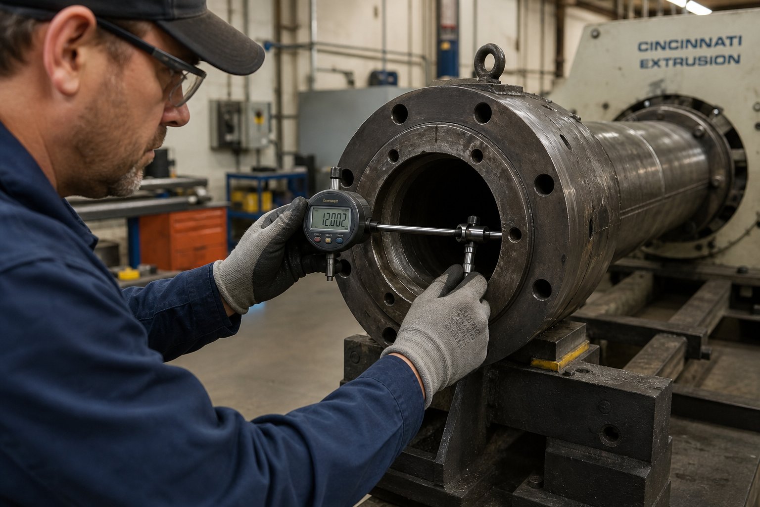
Every routine inspection begins with two things: a clean bore and the right measurement tool. Davis-Standard recommends using a custom electronic micrometer mounted on a movable sled, calibrated to the original barrel diameter, and advanced through the bore in one-L/D axial increments to record internal diameter readings along the full length. This produces a wear profile — a map showing exactly where and how much the bore has enlarged compared to its original specification.
Not every plant has access to electronic bore gauges. Cylinder bore gauges like the Starrett 452B series, set up with a micrometer or caliper gauge and pushed through the barrel on a marked extension rod, provide a more affordable alternative. Readings become harder to take beyond roughly five feet into the bore, but any decent measurement is better than no measurement — especially in the transition zone where most wear concentrates.
Visual inspection matters just as much as dimensional data. Before inserting any gauge, examine the bore surface for scoring, galling, pitting, or discoloration. Each tells a different story: long axial scratches suggest adhesive contact from a deflected screw, dimpled pitting points to corrosive attack, and a uniformly polished appearance indicates abrasive wear. These visual clues help confirm whether your liner material is actually matched to the wear mechanism it faces.
So when is a barrel too worn to keep running? The SPI Dimensional Guidelines provide the industry-standard reference for screw and barrel wear limits. As a general rule, when the bore diameter has increased by more than 0.002 inches per side per inch of nominal diameter beyond the original specification — meaning the total diametral clearance between screw flight OD and barrel bore has roughly doubled from its original value — output efficiency, melt quality, and pressure stability begin deteriorating noticeably. The original clearance on most machines is approximately 0.001 inch per side per inch of diameter, so doubling that gap significantly increases melt leakage past the screw flights and reduces conveying efficiency.
Here is a practical checklist your maintenance team can follow during every scheduled barrel inspection:
- Remove all residual polymer — Wire-brush the bore and follow with copper gauze to eliminate resin deposits without scratching the liner surface.
- Allow the barrel to cool to room temperature — Thermal expansion skews diameter readings. Measure only at ambient temperature for consistency.
- Record bore diameter at every L/D increment — Take readings from each accessible end, focusing on the transition zone (typically 40-60% of the barrel length from the feed end) where wear peaks.
- Check bore roundness at each measurement point — Rotate the gauge 90 degrees and compare readings. Out-of-round conditions greater than 0.015 mm indicate uneven wear or screw misalignment.
- Photograph or document bore surface condition — Note any scoring, pitting, discoloration, or groove damage with location references tied to your measurement stations.
- Compare all readings to the previous inspection record — The rate of change matters more than the absolute value. Accelerating wear rates signal either a material change, a misalignment issue, or a liner that is wearing through its hardened layer.
- Inspect heater band contact surfaces and thermocouple wells — Damaged external surfaces affect thermal control accuracy, which indirectly influences wear patterns.
- Check barrel alignment — Misalignment between the barrel and gearbox creates uneven screw loading that concentrates adhesive wear on one side of the bore.
Timing matters too. The best maintenance programs schedule inspections at regular intervals — whether measured in operating hours, production cycles, or calendar months — and record every measurement consistently. Over time, these data points create a wear profile that identifies the expected lifespan of each barrel, enabling planned replacement rather than reactive scrambling.
Total Cost of Ownership and Resleeving Economics
The invoice price of a new barrel is the number most purchasing departments focus on. It is also the least important number in the total cost of ownership calculation. What actually determines cost-effectiveness is how many hours of quality production that barrel delivers before it needs to come out of the machine — and what happens to your output, scrap rate, and energy consumption as it wears toward that point.
Think of it this way. As clearances increase, melting efficiency decreases. Operators compensate by increasing screw speed, adjusting barrel temperatures, raising backpressure, or some combination of all three. Each adjustment consumes more energy and stresses the drive system. The incremental changes feel minor — a few RPM here, five degrees there — but they compound over weeks and months. Eventually, the process reaches what industry veterans call the "point of diminishing returns": the limit where no further machine adjustment can maintain acceptable productivity or part quality. At that point, the line either runs at reduced output or shuts down entirely.
The hidden costs between installation and that tipping point are where most processors lose money without realizing it:
- Energy waste — Higher screw speeds and elevated barrel temperatures to compensate for lost conveying efficiency can increase energy consumption by 10-20% or more over the barrel's degradation curve.
- Scrap accumulation — Dimensional variation, surface defects, and inconsistent melt quality from a worn bore generate scrap that gets recycled or discarded — either way, it costs material and labor.
- Throughput erosion — A worn barrel that forces you to slow down from 500 kg/hr to 450 kg/hr represents a 10% capacity loss. On a line running 24/7, that lost output over several months can exceed the cost of a new barrel many times over.
- Unplanned downtime — Running a barrel to failure rather than replacing it on schedule risks a catastrophic shutdown at the worst possible moment — during a rush order, over a weekend, or when replacement parts are weeks away.
This is why a barrel that costs twice as much but lasts three to five times longer almost always wins on a per-hour-of-production basis. The same logic applies when evaluating used extruders or used single screw extruders on the secondary market: the barrel condition — not the machine age or brand — determines the true remaining value. A ten-year-old machine with a recently relined barrel can outperform a five-year-old machine running on an original nitrided bore that is past its wear limit. When shopping for a used twin screw extruder, always request bore gauge records and liner composition data before committing. A used twin screw extruder for sale without documented barrel measurements is a gamble that experienced buyers avoid.
Resleeving — removing the worn liner and centrifugally casting a new alloy layer inside the existing barrel shell — offers a middle path between running a worn barrel and buying a new one. Economically, resleeving makes sense when the barrel's external structure, flanges, and alignment surfaces are still in good condition and only the bore surface has degraded. The cost of resleeving typically runs 40 to 60% of a new barrel, and the turnaround time is often shorter than ordering new. For shorter injection-style barrels, where localized wear zones can be addressed without resleeving the full length, the savings are even more compelling.
Resleeving becomes less attractive as barrel length increases. On long extrusion barrels — particularly those with L/D ratios of 30:1 or higher — the cost of resleeving the entire bore approaches or even exceeds replacement cost, while also introducing risk if the base steel has been compromised by heat cycling or external corrosion. In those cases, a new barrel with a fresh liner delivers a known starting point and a full service life ahead of it.
The smartest approach? Document every barrel's wear history from the day it is installed. Record bore measurements at consistent intervals, log the resins and filler loadings processed, and track the operating parameter adjustments your operators make as wear progresses. With good record keeping, shutdowns for screw and barrel changes can be predicted with relative accuracy, component life can be optimized, and "running to failure" — along with all its unplanned downtime — can be avoided entirely. That documented wear history also tells you exactly when to order replacement parts, how many spares to stock, and whether your current liner material is delivering the service life your resin demands.
A disciplined lifecycle program transforms barrel replacement from a crisis into a line item on the maintenance calendar. And when the time does come to specify and source that next barrel — whether new, relined, or sourced from the secondary equipment market — having that data in hand puts you in a far stronger position to match the barrel to the job and negotiate with suppliers who understand your application.
How to Specify and Source the Right Extrusion Barrel
You have the wear data, you understand the metallurgy, and you know which liner matches your resin. The question now is practical: how do you turn all of that knowledge into a purchase order that delivers the right extruder screw barrel for your specific line? Processors who skip a structured specification process end up with barrels that look correct on paper but underperform in production — wrong liner chemistry, mismatched thermal zone count, or feed throat geometry that fights the feedstock instead of conveying it.
A repeatable specification workflow eliminates that guesswork. Whether you are replacing a worn-out barrel on a legacy single-screw line, upgrading a twin-screw compounder, or evaluating a Davis-Standard extruder for sale on the secondary equipment market, the decision sequence follows the same logic.
Step-by-Step Barrel Specification Workflow
Never source a barrel based on machine dimensions alone. The resin you process, the fillers it carries, and the wear mechanism it triggers must drive every material and configuration decision — before you ever request a quote.
This workflow distills the selection criteria covered throughout this article into a sequential process your engineering or maintenance team can follow each time a barrel replacement or upgrade is needed:
- Identify the resin and filler package. List every polymer family and additive your line processes — including secondary formulations, color concentrates, and regrind percentages. The most demanding material in your rotation dictates the minimum liner specification. A barrel sized only for your primary resin will be destroyed by the occasional run of glass-filled nylon or flame-retardant compound.
- Determine the primary wear mechanism. Review your bore inspection records and bore surface condition notes. Is the damage abrasive (smooth, polished bore enlargement), corrosive (pitting and dimpling), adhesive (scoring from screw contact), or a combination? The wear mechanism points directly to the liner alloy chemistry — iron-based bimetallic for abrasion, nickel-based for corrosion, tungsten carbide for extreme filler loading.
- Select the barrel liner material. Match the identified wear mechanism and resin family to the liner comparison table from your polymer-to-barrel compatibility analysis. Confirm that the liner hardness, corrosion resistance, and maximum operating temperature all exceed the demands of your worst-case processing scenario — not just the average run.
- Specify feed throat type and geometry. Decide between smooth-bore and grooved feed based on your resin family and throughput targets. Grooved feeds deliver 20 to 40% higher output on dedicated polyolefin lines but require intensive water cooling, hardened groove surfaces, and higher drive torque. For mixed-resin operations or heat-sensitive polymers, smooth-bore feeding offers broader versatility.
- Confirm thermal zone count and heater specifications. Verify the number of independent heating and cooling zones, heater band type (mica, ceramic, or cast-aluminum), and cooling method (air or liquid). Ensure that the zone layout matches your process temperature profile requirements and that the total installed wattage can reach setpoint temperatures within an acceptable startup window.
- Verify dimensional and tolerance specifications. Confirm bore diameter, bore roundness tolerance, surface roughness (Ra), overall length, flange dimensions, and thermocouple well locations against your machine platform requirements. For segmented barrels, verify joint alignment tolerances and flange bolt torque specifications.
- Request material certifications and inspection documentation. Any reputable supplier provides bore hardness test results, liner thickness verification, surface roughness measurements, and alloy composition certification with each barrel. If a supplier cannot or will not furnish these documents, treat that as a disqualifying red flag.
- Evaluate the supplier's custom engineering capability. Complex applications — multi-resin operations, vented barrel configurations, or non-standard L/D ratios — require a supplier that engineers solutions rather than simply cataloging standard sizes. Confirm that the supplier can match extruder screws to the barrel specification, offer segmented barrel options if needed, and provide technical support for resin-specific challenges.
Steps one through three are non-negotiable for every replacement. Steps four through eight add the configuration and sourcing detail that separates a barrel that merely fits the machine from one that is genuinely optimized for the application.
Sourcing Custom and Replacement Barrel Solutions
The US extruders market spans everything from OEM replacements for major platform brands to custom-engineered solutions from specialized manufacturers. When sourcing, you will encounter three broad supplier categories: original equipment manufacturers who sell replacement parts at premium pricing, independent domestic rebuilders who resleeve or remanufacture barrels, and international manufacturers who produce new barrels and extruder screws to specification at competitive cost points.
Each category has a role. OEM parts guarantee dimensional compatibility but often carry the longest lead times and highest prices. Domestic rebuilders offer fast turnaround on resleeving and can be ideal for emergency replacements. International manufacturers — particularly those with dedicated screw and barrel engineering teams — deliver the best value when you need custom liner chemistries, non-standard configurations, or matched screw-and-barrel sets engineered for specific resin families.
For processors and equipment manufacturers seeking custom-engineered or replacement extrusion barrels and screws, NANHAIYA's screw barrel product center serves as a practical sourcing resource. Their product line covers both extrusion and injection molding barrel and screw configurations, with the custom engineering capability to match liner materials, feed throat designs, and thermal zone layouts to specific resin and application combinations — exactly the kind of application-specific matching this workflow demands.
Whether you are specifying a new barrel for an active production line, sourcing components for a Davis-Standard extruder for sale that needs barrel refurbishment before recommissioning, or building spare parts inventory based on documented wear rate data, the specification workflow above ensures that every barrel you purchase is matched to the job it actually has to do. Price comparisons only become meaningful after the technical specification is locked — because the cheapest barrel that wears out in six months is always the most expensive barrel you will ever buy.
Frequently Asked Questions About Extrusion Barrels
1. What is the difference between an extrusion barrel and an injection molding barrel?
An extrusion barrel operates continuously with longer L/D ratios (24:1 to 36:1) and sustained pressures of 100-400 bar, ending in a die adapter. An injection molding barrel uses a cyclic reciprocating screw with shorter L/D ratios (18:1 to 24:1), thicker walls to handle intermittent pressure spikes up to 2,000 bar, and terminates with a nozzle and check valve. These differences affect liner selection, wear patterns, and maintenance intervals, making the two barrel types non-interchangeable even when bore diameters match.
2. How do I know when my extrusion barrel needs to be replaced?
Measure bore diameter at every L/D increment using a bore gauge and compare readings to the original specification. According to SPI Dimensional Guidelines, replacement is recommended when bore enlargement exceeds roughly 0.002 inches per side per inch of nominal diameter — effectively doubling the original screw-to-barrel clearance. Visual signs include axial scoring from adhesive wear, dimpled pitting from corrosive attack, and uniformly polished surfaces from abrasive wear. Tracking measurement trends over time helps predict replacement windows before output quality degrades. Suppliers like NANHAIYA (nhyscrew.com/products) can provide matched replacement barrel and screw sets engineered for your specific resin and wear conditions.
3. What barrel liner material is best for processing glass-filled polymers?
For glass fiber loadings above 30%, tungsten carbide bimetallic liners (Ni+WC+Cr+B) are the recommended choice because embedded carbide particles resist the severe abrasive action of glass fibers far more effectively than nitrided steel or standard iron-based liners. For lower fill percentages (15-30%), iron-based bimetallic liners (Fe+Ni+Cr+B) with hardness values of 58-62 HRC provide a cost-effective balance of abrasion resistance and service life. Nitrided barrels should be avoided entirely for any glass-filled compound, as the thin hardened case wears through rapidly, exposing soft core steel.
4. What are the advantages and disadvantages of grooved feed barrel technology?
Grooved feed barrels use machined longitudinal grooves in the feed section to physically lock pellets and prevent rotation, boosting output by 20-40% per RPM compared to smooth-bore designs. Additional benefits include lower melt temperatures, improved pressure stability, and significant energy savings. However, grooved feeds require intensive water cooling, hardened groove surfaces, larger gearboxes for higher torque demands, and tighter control of pellet size and regrind ratios. They perform best on dedicated polyolefin lines and are less suited for soft elastomers, high-melt-temperature resins, or vented extrusion applications.
5. Is it more cost-effective to resleeve an extrusion barrel or buy a new one?
Resleeving costs roughly 40-60% of a new barrel and makes economic sense when the barrel shell, flanges, and alignment surfaces remain in good condition and only the bore surface is degraded. It is especially viable for shorter injection-style barrels with localized wear zones. However, for long extrusion barrels with L/D ratios of 30:1 or higher, resleeving the entire bore often approaches or exceeds replacement cost while introducing risk if the base steel has been compromised by heat cycling. The total cost of ownership calculation should also account for energy waste, scrap accumulation, and throughput erosion caused by running a worn barrel beyond its effective service window.
Written by
Nanhaiya Technical Team
Zhoushan Nanhaiya Plastic Machinery Co., Ltd.
The Nanhaiya technical team supports screw and barrel manufacturing projects through application review, technical communication, custom manufacturing coordination, and production and quality control.
Discuss Your Application
Related Articles
More insights on screw barrel technology and plastics processing.

What Nobody Tells You About Screw Barrel For Plastic Machine Design
Oct 10, 2026
Learn how screw barrel for plastic machine design affects melt quality, throughput, and wear life. Covers geometry, resin matching, troubleshooting, and sourcing.
Read Article
Single Screw Extruder for Sheet: Stop Guessing, Start Specifying
Oct 9, 2026
Learn how to specify a single screw extruder for sheet production. Covers screw geometry, resin-specific processing, troubleshooting, and maintenance best practices.
Read Article
PE Pipe Extruder Machine: What Datasheets Won't Tell You
Oct 9, 2026
Learn how a PE pipe extruder machine works, key specs explained, material grade selection, maintenance tips, and buyer guidance beyond the datasheet.
Read ArticleLooking for something else?
Search by material, symptom or product and jump straight to the relevant page.
These are navigation suggestions based on keyword matching — not a quotation, not a delivery commitment, and not a substitute for engineering review. Final specification is confirmed by our engineers against your drawings and processed material.
Need help with screw barrel selection?
Share your machine model, processed material and application. Our team can help with pricing and technical support.