

What an Extruder Twin Screw Barrel Actually Does
When a twin screw extruder starts underperforming, where does your attention go first? If you're like most engineers and process technicians, you immediately think about the screws. Screw element configuration, wear on flight tips, kneading block geometry — these get dissected in detail. But the barrel? It's often treated as a passive shell, a background component that simply holds everything together. That assumption is exactly why so many barrels wear out long before they should.
An extruder twin screw barrel is the precision-bored, temperature-controlled cylinder that houses two co-rotating or counter-rotating screws, providing the confined processing environment for polymer melting, mixing, and pressure generation.
Defining the Twin Screw Barrel and Its Role in Extrusion
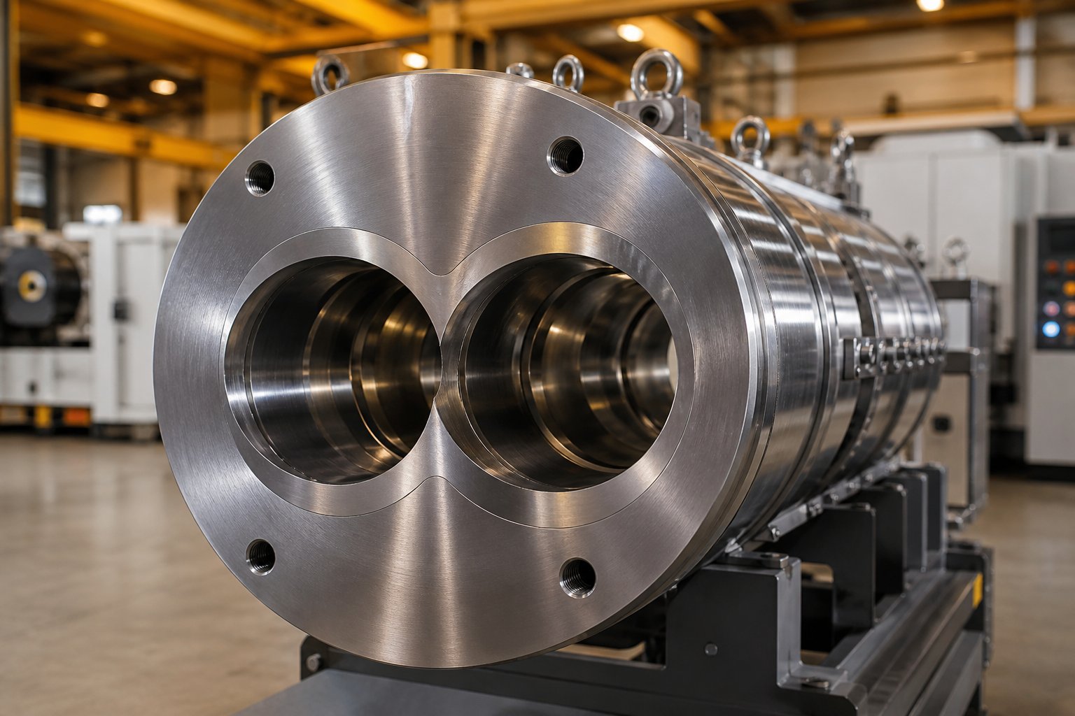
At its most fundamental level, an extruder barrel is the cylindrical housing that encloses two intermeshing screws, forming the pressurized chamber where every critical processing step takes place — solid conveying, melting, dispersive and distributive mixing, devolatilization, and final pressure buildup before the die. The barrel's internal bore geometry, typically a figure-eight profile in parallel designs, creates the confined space that forces material interaction with the rotating screw elements. Without this tight geometric boundary, the shear rates and pressure profiles that drive effective compounding simply cannot exist.
Twin screw extruders rely on the barrel to do far more than contain the melt. Each extruder barrel segment houses independent heating elements and cooling channels, establishing the thermal zones that control exactly where and how fast the polymer transitions from solid pellets to homogeneous melt. Thermocouple ports embedded in the barrel wall feed real-time temperature data back to the control system, making the barrel an active participant in process regulation — not a passive bystander.
Why the Barrel Deserves as Much Attention as the Screw
Consider what the barrel endures during a typical production run. It resists internal pressures that can exceed 200 bar in high-output compounding operations. It absorbs abrasive wear from glass fibers, mineral fillers, and pigment particles scraping across its bore surface at high velocity. It withstands corrosive attack from acidic byproducts generated during PVC processing or flame-retardant formulations. And it does all of this while maintaining bore tolerances measured in hundredths of a millimeter.
The financial stakes are significant. Replacing extruder screws and barrels on a production-scale twin screw system can cost anywhere from $20,000 to well over $100,000, depending on diameter, length, and metallurgy. Major overhauls involving barrel and screw replacement typically occur every 25,000 to 40,000 operating hours, as industry cost analyses suggest. When improper barrel specification accelerates that timeline, the result is unplanned downtime, inconsistent melt quality, and maintenance budgets blown wide open.
This article bridges the gap between the oversimplified overviews you'll find online and the dense manufacturer spec sheets that assume deep metallurgical expertise. Whether you're an engineer specifying a replacement extruder screw barrel, a process technician troubleshooting declining output quality, or a procurement professional evaluating supplier quotes, the goal here is practical depth — the kind that helps you understand not just what a twin screw barrel is, but why certain barrels fail prematurely and how to prevent it.
That deeper understanding starts with the barrel's physical anatomy — its bore geometry, its modular construction, and the heating and cooling systems that make precision thermal control possible.
Anatomy of a Twin Screw Barrel From Feed Throat to Discharge
Picture slicing a twin screw barrel in half at any point along its length. What you'll see is not a simple circle — it's a figure-eight. That cross-sectional profile is the geometric foundation of every parallel twin screw barrel, and it dictates how material flows, how pressure builds, and where wear concentrates. Understanding this anatomy is the first step toward understanding why barrels fail.
Figure-Eight Bore Geometry and Barrel Configurations
In a parallel co-rotating or counter-rotating design, the barrel bore consists of two overlapping cylindrical channels machined to extremely tight tolerances. The centerline distance between the two bores — the distance separating the axes of the two screws — determines how deeply the screw flights intermesh and, consequently, how aggressively the self-wiping action cleans the bore walls. Too much centerline deviation and you lose mixing efficiency. Too little, and the screw elements collide.
Conical designs take an entirely different approach. Instead of parallel bores, the screw tube tapers from a larger diameter at the feed end to a smaller diameter at the discharge. This taper generates natural compression without requiring changes in screw root diameter, making conical extruder barrels well suited for rigid PVC applications where gradual pressure buildup matters more than aggressive mixing.
Modular Segmented Barrels Versus Monolithic Construction
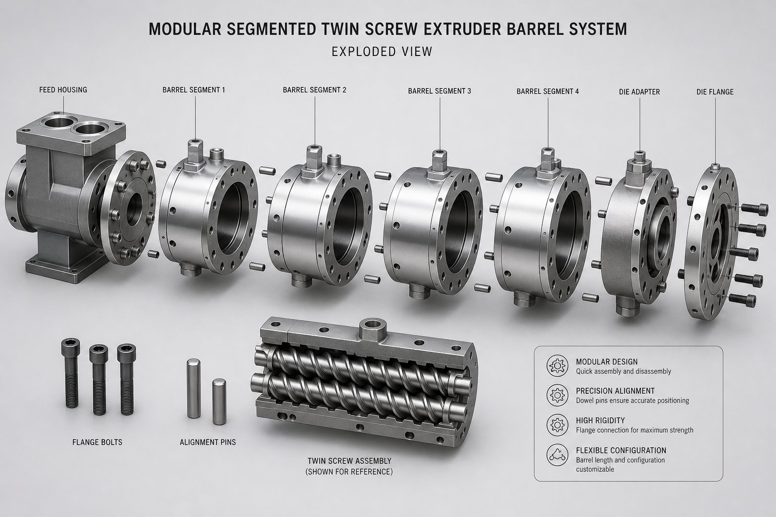
Imagine needing to replace an entire six-foot barrel because a two-inch section near the feed zone wore out. That's the reality with monolithic one-piece construction. Modular segmented barrels solve this problem elegantly — individual barrel sections, typically 4D to 5D in length (four to five times the bore diameter), bolt together using precision alignment dowel pins to form the full processing length.
Each segment can serve a distinct purpose. One section might feature an open feed throat with a water-cooled jacket to prevent premature melting of the incoming polymer. Another might incorporate a vacuum vent port for degassing. Yet another could include reinforced lateral openings for side feeding of fillers. This flexibility is why modular construction dominates modern compounding lines, as industry analysis of segmented barrel systems consistently confirms — if one segment wears out, you replace that segment alone, saving both time and cost.
Monolithic barrels still have their place, though. For small-diameter laboratory extruders or short-length machines where modular joints would compromise rigidity, a single-piece barrel and screw arrangement can provide superior alignment precision and structural stiffness.
| Criteria | Modular Segmented Barrel | Monolithic One-Piece Barrel |
|---|---|---|
| Configuration Flexibility | High — segments rearranged or swapped for venting, feeding, or closed processing | Low — fixed bore configuration along entire length |
| Replacement Cost | Lower — only worn segments replaced individually | Higher — entire barrel must be replaced even for localized wear |
| Alignment Precision | Dependent on dowel pin and bolt torque integrity between segments | Excellent — no joints to introduce misalignment |
| Structural Rigidity | Good when properly assembled, but joints are potential weak points | Superior — continuous structure with no segment interfaces |
| Typical Applications | Production-scale compounding, masterbatch, reactive extrusion | Lab-scale extruders, small-diameter machines, simple profiles |
Heating, Cooling, and Temperature Zone Control
Every extruder barrel segment is its own thermal zone. Heating is provided by one of three common methods: cartridge heaters embedded directly into machined bores in the barrel wall, cast aluminum heater bands clamped around the barrel exterior, or ceramic band heaters that offer faster response times and higher watt densities. The choice depends on the barrel diameter, operating temperature range, and how quickly you need to recover setpoint after a process upset.
Cooling is equally critical — and often overlooked. Liquid circulation channels drilled through the barrel walls carry water or oil to extract heat from zones where shear-generated energy pushes temperatures above setpoint. Some extruder feed barrel designs rely on forced air cooling instead, particularly in zones where moderate cooling rates are sufficient. Thermocouple ports drilled into each segment reach close to the bore surface, feeding real-time temperature data to closed-loop controllers that balance heating and cooling to maintain the target profile.
Beneath all of this thermal infrastructure sits the barrel liner — the bore surface that directly contacts the processed material. Nitrided steel surfaces, where nitrogen is diffused into the bore to create a hard case layer, work well for unfilled or lightly filled polymers. Bimetallic liners, typically centrifugally cast alloys containing tungsten carbide or boron-based compounds, provide dramatically better abrasion resistance for glass-fiber-filled or mineral-loaded compounds. Fully hardened tool steel sleeves or powder metallurgy inserts address the most extreme wear environments. The processed material's abrasiveness, corrosivity, and operating temperature ultimately drive which liner makes financial sense — a topic that becomes even more important when you consider how different barrel geometries interact with specific screw configurations and the unique demands each twin screw design places on the bore.
Co-Rotating Versus Counter-Rotating Barrel Designs
Not all figure-eight bores are created equal. The direction the screws rotate — and whether those bores run parallel or taper from feed to discharge — fundamentally changes what the barrel must endure. Choosing the wrong configuration doesn't just limit processing performance; it accelerates wear in ways that can cut barrel life in half. Here's how each design differs and why it matters for your application.
Co-Rotating Parallel Barrel Requirements
In a co-rotating twin screw extruder, both screws spin in the same direction inside two identical-diameter parallel bores. The centerline distance between bores is carefully engineered so the screw flights intermesh deeply enough to create a self-wiping action — material clinging to one screw gets scraped off by the adjacent flight, preventing stagnation and dead zones. This self-wiping geometry is what makes co-rotating systems exceptional at dispersive and distributive mixing.
What does this mean for the barrel? Speed. Co-rotating parallel systems typically operate at screw speeds ranging from 200 to 1,200+ RPM, significantly faster than their counter-rotating counterparts. That high rotational velocity translates directly into elevated shear stress at the bore wall, increased frictional heat generation, and faster abrasive erosion when processing filled compounds. The barrel metallurgy must be hard enough to resist this constant high-speed contact, yet tough enough to avoid brittle cracking under cyclical thermal loads. Bimetallic liners with tungsten carbide particulates are common choices for this reason.
Bore tolerances on co-rotating barrels are tight — typically within 0.02 to 0.05 mm of nominal diameter — because even small deviations alter the shear gap between screw flight tips and bore wall. That gap drives mixing intensity. Too loose, and melt bypasses the kneading zones without adequate shear. Too tight, and metal-to-metal contact accelerates adhesive wear on both the barrel and screw elements. Co-rotating parallel barrels dominate in compounding, masterbatch production, reactive extrusion, and any process where intensive mixing at high throughput rates is the priority.
Counter-Rotating and Conical Barrel Distinctions
Flip the rotation direction, and the barrel's job changes dramatically. In a counter-rotating twin screw extruder, the screws spin in opposite directions, creating what engineers call a "calender gap" — the narrow nip zone where the two screws meet and material gets squeezed between them. This calender gap generates a positive-displacement pumping action, meaning the barrel experiences higher localized pressures but at significantly lower screw speeds, often in the range of 5 to 50 RPM for intermeshing counter-rotating designs.
Lower speed doesn't mean lower demands on the barrel. Counter-rotating barrels must maintain extremely precise bore-to-screw clearances in the calender gap region, because even minor wear enlarges that gap and destroys the positive-displacement seal that gives these machines their pressure-building advantage. The thermal management profile also differs: slower speeds generate less shear heat, so heating systems must work harder to maintain target melt temperatures, while cooling demands are more modest. This configuration — sometimes referred to as a double screw extruder in broader industry usage — is the workhorse behind PVC profile, pipe, and sheet extrusion lines, where gentle material handling and precise pressure control outweigh the need for aggressive mixing.
Conical twin screw extruders take counter-rotation a step further by abandoning parallel geometry entirely. Imagine two tapered bores that converge from a large diameter at the feed end to a smaller diameter at the discharge. This tapered bore geometry creates natural compression as material advances — the decreasing cross-section squeezes the melt progressively without requiring changes in screw root diameter or flight depth. The barrel of a conical twin screw extruder must be machined with precision taper angles, and bore wear tends to concentrate near the discharge end where pressures peak. Conical barrels are compact, deliver excellent torque transfer due to the larger root diameter at the drive end, and are commonly found in rigid PVC pipe and window profile lines where medium-capacity production and space efficiency matter.
Understanding these distinctions is more than academic. The barrel configuration you select determines which wear mechanisms dominate, which metallurgy makes sense, and ultimately how long that barrel lasts before it needs replacement. The comparison below puts the key differences side by side:
| Criteria | Co-Rotating Parallel | Counter-Rotating Parallel | Conical (Counter-Rotating) |
|---|---|---|---|
| Bore Geometry | Two identical-diameter parallel bores in figure-eight profile | Two identical-diameter parallel bores with tighter calender gap | Two tapered bores converging from feed to discharge |
| Typical Speed Range | 200 – 1,200+ RPM | 5 – 50 RPM (intermeshing) | 5 – 40 RPM |
| Pressure Capability | Moderate — relies on screw element design for pressure buildup | High — positive displacement pumping generates strong die pressure | High — natural taper compression builds pressure progressively |
| Primary Applications | Compounding, masterbatch, reactive extrusion, devolatilization | PVC profiles, pipe extrusion, sheet extrusion | Rigid PVC pipe, window profiles, medium-capacity lines |
| Dominant Wear Profile | Abrasive and adhesive wear concentrated at kneading zones due to high RPM | Localized wear at calender gap; corrosive wear common in PVC applications | Wear concentrated near discharge where compression peaks; corrosion from PVC degradation |
Each of these configurations also places different demands on thermal zone management. Co-rotating barrels need aggressive cooling capacity to offset shear-generated heat in mixing-intensive zones. Counter-rotating and conical barrels rely more heavily on heating capacity to keep slower-moving, lower-shear material at target melt temperature. Selecting the right twin-screw extruder barrel configuration — and specifying the metallurgy and thermal systems that match — is the foundational decision that every subsequent specification builds upon.
Yet configuration alone doesn't tell the whole story. Even within the same barrel type, a seemingly simple specification — the ratio of processing length to bore diameter — can make or break the balance between mixing quality, throughput, and polymer degradation.
L/D Ratio and Barrel Length Selection Explained
That ratio — processing length divided by bore diameter — is known as L/D, and it is arguably the single most consequential number on any extruder twin screw barrel specification sheet. Get it right, and you unlock the ideal balance of mixing, throughput, and thermal control. Get it wrong, and you're either degrading sensitive polymers with excessive heat history or struggling with inadequate dispersion that no screw configuration can fix.
Understanding L/D Ratio and Its Processing Impact
The concept is straightforward. Take the total active processing length of the barrel — from the downstream edge of the feed opening to the discharge flange — and divide it by the nominal bore diameter. A barrel with a 1,200 mm processing length and a 50 mm bore diameter has an L/D of 24:1. Double that length to 2,400 mm on the same diameter, and you're at 48:1.
In practice, twin screw extrusion barrels typically range from 24:1 to 48:1, with some specialized configurations pushing beyond 52:1 for demanding applications. Industry data from compounding equipment manufacturers shows that production-scale machines commonly fall between 28:1 and 40:1, while laboratory and pilot-scale systems sometimes use shorter ratios to accommodate space constraints or small-batch development work.
Why does this number matter so much? Because the L/D ratio directly governs how many distinct processing zones you can fit along the barrel. Each zone corresponds to a specific unit operation — feeding, melting, mixing, venting, pressure generation — and every one of those operations requires a dedicated length of barrel and a corresponding extruder screw element configuration underneath it. More length means more zones, more flexibility, and more opportunity to refine the melt before it exits the die.
A typical barrel layout, regardless of L/D, follows this sequential progression of processing zones:
- Solid conveying and feeding — Raw material enters through the feed throat and is transported forward by screw flights operating in a starved-fed condition.
- Melting and plasticating — Kneading blocks and restrictive elements convert mechanical energy into heat, transitioning solid pellets or powder into a continuous melt.
- Mixing and kneading — Dispersive and distributive mixing elements break down agglomerates and homogenize additives, fillers, or polymer blends throughout the matrix.
- Venting and degassing — Atmospheric or vacuum vent ports allow moisture, volatiles, and entrained air to escape from the melt through open barrel segments.
- Melt conveying and pressure generation — Tight-pitched conveying elements build the die pressure required for stable output through the downstream forming system.
- Discharge — The fully processed, pressurized melt exits the barrel through the end flange into a die, pelletizer, or downstream shaping system.
How Barrel Length Affects Residence Time and Mixing Intensity
Here's the tradeoff that trips up even experienced engineers: a longer barrel gives you more real estate for screw extrusion operations, but it also keeps the polymer inside the heated, high-shear environment for a longer period. That additional residence time — typically ranging from 15 seconds to over one minute in co-rotating systems — can be beneficial or destructive, depending on the material.
For highly filled compounds, color masterbatches, or formulations requiring multiple additive additions and thorough devolatilization, a higher L/D (36:1 to 48:1) provides the room you need. You can incorporate multiple kneading zones, downstream side-feed positions, and two or more vent ports without crowding the extrusion screw design. The result is better dispersion, more complete moisture removal, and higher achievable throughput rates.
But push the L/D too high for thermally sensitive materials — certain biodegradable polymers, shear-sensitive elastomers, or reactive formulations with narrow processing windows — and the extended thermal exposure triggers degradation, discoloration, or unwanted crosslinking. For these materials, a shorter L/D of 24:1 to 32:1 minimizes the time the polymer spends under heat and shear, preserving molecular weight and end-use properties at the cost of reduced mixing capability.
Selecting the Right L/D for Your Application
Bore diameter selection works hand in hand with L/D ratio to determine throughput capacity. A larger bore diameter increases the available free volume inside the barrel — the space between the screw elements and barrel wall where material actually resides and gets processed. Doubling the bore diameter doesn't just double throughput; it can increase it by a factor of four or more, because free volume scales with the square of the diameter. This is why production-scale extruder twin screw systems in the 90 mm to 135 mm diameter range can achieve outputs of several thousand kilograms per hour, while a 27 mm laboratory machine might max out at 50 kg/h.
The beauty of modular segmented barrel construction — discussed earlier — becomes especially apparent here. Need a longer processing length for a new formulation requiring additional venting? Add barrel segments to increase the L/D from 36:1 to 44:1 without replacing the gearbox, motor, or frame. Running a simpler formulation that doesn't need extensive mixing? Remove segments to shorten the barrel, reduce residence time, and lower energy consumption. This adjustability is one reason modular barrel systems have become the standard in compounding operations — the same machine can be reconfigured as product requirements evolve.
When evaluating L/D for a specific application, consider these factors in order: the thermal sensitivity of your base polymer, the complexity of your formulation (number of additive streams, filler loadings, liquid injections), the devolatilization demands (moisture content, volatile byproducts), and your target production rate. A general-purpose compounding line processing glass-filled engineering plastics at moderate rates will perform well at 36:1 to 40:1. A high-output masterbatch line with multiple pigment additions and aggressive vacuum venting may benefit from 44:1 to 48:1. A line dedicated to shear-sensitive TPU or reactive extrusion might run best at 28:1 to 32:1.
Getting the L/D right sets the stage for everything else — but even a perfectly specified barrel length can't compensate for poor venting design. The positioning, geometry, and type of vent ports along that barrel length determine whether volatiles escape cleanly or cause vent flooding, surface defects, and downstream quality problems.
Barrel Venting and Degassing Port Engineering
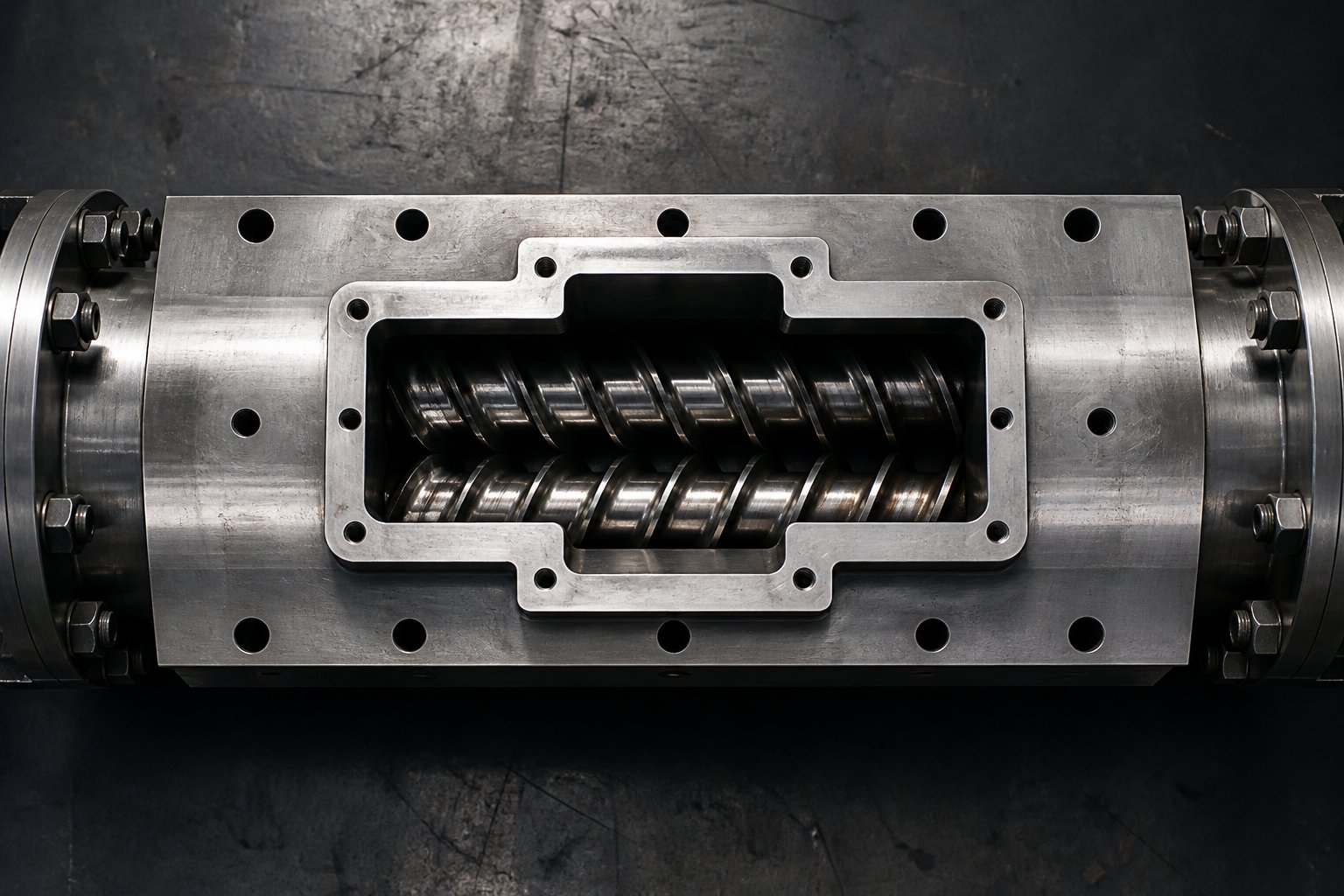
Volatiles trapped inside a compound don't disappear on their own. Moisture, entrained air, residual monomers, and gaseous byproducts from thermal decomposition all need a controlled exit path — and that path runs directly through the barrel wall. In a modular extruder twin screw barrel, specific segments can be configured with open vent ports or vacuum ports positioned at precise locations along the processing length, turning what would otherwise be sealed steel into a carefully engineered degassing system. Get the vent design wrong, and you'll face porous pellets, surface defects in finished parts, or — worse — melt erupting out of the vent opening and forcing an unplanned shutdown.
Atmospheric and Vacuum Vent Port Design
Every twin screw extrusion process that involves moisture-sensitive resins, volatile additives, or high-filler-loading formulations relies on at least one — and usually two or more — vent openings along the barrel. These fall into two categories, each serving a distinct purpose.
Atmospheric vents are the simpler of the two. These are open ports in the top of a barrel segment, positioned downstream of the initial melting zone, that allow gases to escape at ambient pressure. When the polymer first melts and releases trapped air or surface moisture, an atmospheric vent provides a low-resistance escape path. The geometry of the opening matters enormously: it must be large enough to handle the volume of escaping vapor without creating excessive exit velocity, yet shaped so that the melt itself doesn't climb out. As industry experts have documented, when vapor velocity through the vent opening gets too high — because there's too much gas volume relative to the vent area — exiting gases entrain solids or melt, pulling material right out of the barrel.
Vacuum vents raise the stakes. Positioned closer to the discharge end of the barrel, these ports connect to an external vacuum pump that pulls residual volatiles from the melt under negative pressure, typically in the range of 100 to 300 mbar. This additional driving force dramatically improves mass transfer, extracting volatiles that atmospheric pressure alone can't remove. The challenge? Vacuum creates a powerful suction force that can pull molten polymer up and out of the screw channel if conditions aren't right.
Two conditions must be satisfied for stable vacuum venting. First, the screw elements directly underneath the vent port must maintain a low degree of fill — typically long-pitch conveying elements that transport material forward without building pressure. This keeps the melt level well below the vent opening. Second, a "melt seal" — a section of fully filled screw created by kneading blocks or reverse-flight elements — must exist upstream of the vent to prevent vacuum from sucking air backward through the barrel, which would destroy the pressure profile and flood the vent with polymer.
When melt does flood a vacuum vent, the cause is often an increase in backup length — the length of filled screw needed to generate downstream die pressure. Screen fouling, die holes freezing off, or progressive screw and barrel wear in the pumping section can all push the filled zone upstream until it reaches the vent opening. Mechanical vent stuffers — small twin-screw devices mounted inside the vent port — offer a solution for particularly difficult materials. These stuffers physically prevent melt from expanding out of the screw channel while still allowing gases to travel axially through the stuffer screws and escape. Heated side vent designs are another option, keeping accumulated polymer at temperature to prevent degradation and black speck contamination.
Side-Stuffing Ports for Downstream Filler Addition
Imagine trying to feed glass fibers through the main feed throat of a compounding extruder. They'd pass through the high-shear melting zone and get ground into powder, destroying the fiber aspect ratio that gives the finished compound its strength. This is exactly why side-stuffing barrel segments exist — and why their design differs significantly from standard closed barrel sections or simple vent barrels.
A side-feed barrel segment, often called a "combi-barrel," features a large lateral opening machined through the barrel wall that connects to a twin-screw side feeder. This side feeder pushes solid materials — glass fibers, mineral fillers, low-bulk-density powders, or secondary polymer streams — directly into the molten polymer already flowing through the main extruder barrel. The combi-barrel also incorporates an atmospheric vent opening above the feed zone to release the substantial volume of entrained air that arrives with the incoming solids. The lower the bulk density of the filler, the more air enters the barrel and the larger the vent area needs to be.
Structurally, side-feed barrel segments must be reinforced around the lateral opening to compensate for the material removed from the barrel wall. The bore geometry at the junction between the side feeder and the main barrel must align precisely so that the side feeder screws push material smoothly into the main screw channel without creating dead zones or material hang-up points. Standard conveying elements — not specialized feed elements — should be used in the main screw underneath the side-feed opening, extending at least one screw diameter upstream and continuing into the adjacent downstream closed barrel section. Using undercut "SK" type feed elements in this zone is generally inadvisable because the undercut isn't self-wiped when surrounded by molten polymer, allowing material to accumulate, degrade, and generate black specks.
A twin screw compounding extruder running glass-fiber-filled nylon at high loadings might use two side-feed barrels — one for the primary filler addition and another farther downstream for a secondary additive stream — each with its own atmospheric vent to handle displaced air. A compounding twin screw extruder producing heavily filled masterbatch with 60-80% calcium carbonate may require multiple atmospheric vents surrounding the side-feed position simply to manage the enormous volume of air introduced with the low-density powder.
The versatility of modular barrel construction becomes fully apparent when you consider the range of specialized segment types available in a modern system:
- Closed barrel segment — Standard sealed section for conveying, melting, and mixing zones where no material addition or gas removal is needed.
- Atmospheric vent barrel — Open top port for releasing air, moisture, and low-level volatiles at ambient pressure; used after initial melting zones and adjacent to side feeders.
- Vacuum vent barrel — Sealed port connected to an external vacuum system for deep devolatilization of residual solvents, monomers, or moisture under negative pressure.
- Side-feed barrel (combi-barrel) — Reinforced segment with lateral opening for twin-screw side feeder connection, typically combined with an atmospheric vent for air displacement.
- Liquid injection barrel — Segment with a drilled and tapped port for injecting liquid additives, plasticizers, or reactive agents directly into the melt via a spring-loaded or pressurized injector.
- Feed barrel with cooling jacket — The first barrel segment in the line, featuring a water-cooled throat to keep incoming solids below their softening point and prevent bridging.
Each of these segment types can be rearranged, added, or removed as formulation requirements change — a flexibility that makes the modular barrel concept indispensable for any operation running multiple products on the same line. Positioning vents and side feeders correctly along the barrel length is not a trial-and-error exercise; it requires deliberate coordination with the screw element configuration underneath each barrel segment to ensure that fill levels, pressure profiles, and melt seal positions all align with the barrel's open and closed zones.
That coordination — the intimate relationship between what happens inside the barrel bore and the screw elements rotating within it — is exactly where many wear problems originate. Certain screw element types concentrate enormous forces on specific barrel zones, and understanding which elements drive the hardest wear is the key to predicting where your barrel will fail first.
Barrel Wear Mechanisms and How Materials Fight Back
Knowing that kneading blocks and reverse-flight elements hammer specific barrel zones is useful. But understanding how that damage actually occurs — at the metallurgical level — is what separates reactive maintenance from proactive barrel specification. Barrel wear is not a single phenomenon. Four distinct mechanisms attack the bore surface, often simultaneously, and each one demands a different defensive strategy from the barrel's metallurgy.
Abrasive and Corrosive Wear in Twin Screw Barrels
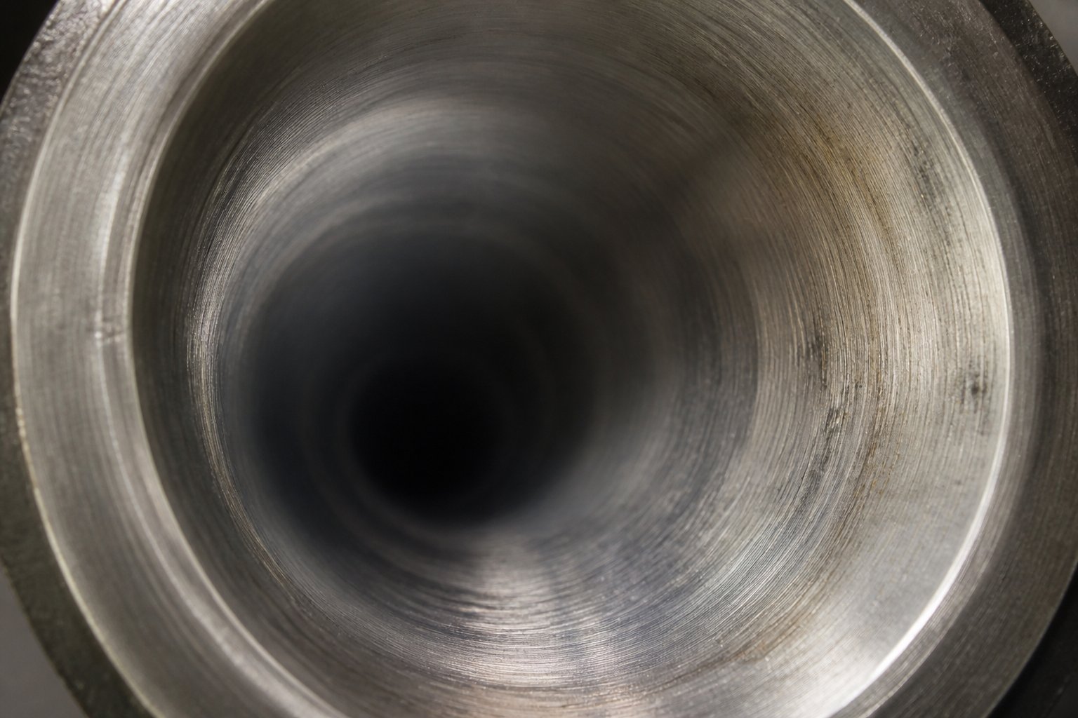
Abrasive wear is the most common killer of extruder screw and barrel systems in compounding operations. Every time a hard filler particle — glass fiber, calcium carbonate, titanium dioxide, talc, or wood flour — is forced across the bore surface by rotating screw elements, it acts like microscopic sandpaper. The sharp machined edges of screw flights and kneading blocks gradually appear rounded, smooth, and occasionally polished as material erodes them, and the bore wall suffers identical damage in mirror image. The severity depends on several factors: filler hardness (glass fibers are far more aggressive than calcium carbonate), filler concentration, particle shape (angular particles cut faster than rounded ones), screw speed, and total throughput volume. This type of wear tracks with kilograms processed, not hours on the clock — a line running 30% glass-fiber-filled PA66 at high output can erode a standard nitrided bore in as little as six to twelve months.
Corrosive wear is subtler but equally destructive. When PVC degrades under heat, it releases hydrochloric acid. Halogenated flame retardants generate similar corrosive byproducts. These acidic compounds chemically attack the barrel bore, creating a dimpled or pitted surface texture that weakens the metal and accelerates mechanical erosion. What makes corrosion particularly insidious is that it doesn't require extreme processing conditions — even moderate temperatures combined with trace moisture can trigger acid formation in PVC formulations, steadily undermining the bore metallurgy between production runs if residual material isn't properly purged.
In many real-world applications, abrasive and corrosive wear operate together. A PVC cable compound loaded with 30% calcium carbonate, for example, subjects the barrel to simultaneous acid attack and mineral abrasion. Field data from production lines shows that nitrided barrels processing this combination last only 12 to 18 months, while nickel-chromium-boron bimetallic liners extend service life to 36 to 60 months — precisely because the nickel-based alloy resists both corrosion chemistry and particulate erosion at the same time.
Adhesive Wear and Fatigue Cracking Mechanisms
Adhesive wear occurs when metal touches metal — specifically, when screw flight tips contact the barrel bore. You might wonder how that's possible in a system designed to maintain precise clearance between screw and barrel. The answer lies in deflection. Twin screw shafts are rigidly supported at the gearbox end but are essentially cantilevered at the discharge end, relying on the processed melt to provide hydrodynamic support along the barrel length. When screws rotate at high speeds without sufficient melt present — during startup, shutdown, or between production runs — the shafts can deflect and contact the bore wall. The result? Score marks on the barrel surface and flattened screw flight tips, both of which widen the operating clearance and degrade mixing efficiency.
Fatigue cracking is the slowest of the four mechanisms, but potentially the most catastrophic. Every heating cycle expands the barrel; every cooling cycle contracts it. Every pressure pulse from screw element transitions pushes outward on the bore wall, and every relaxation between pulses allows it to spring back. Over thousands of operating hours, these cyclic thermal and mechanical stresses nucleate micro-cracks on the bore surface. The cracks propagate slowly through the liner, eventually reaching a depth where chunks of hardened material can spall off — a condition that not only destroys bore geometry but can contaminate the product with metallic particles. Fatigue cracking is most common at stress concentration points: vent port openings, the junction between barrel segments, and zones underneath aggressive kneading block configurations where pressure oscillations are most severe.
High-speed compounding operations — where screw speeds exceed 600 RPM and rapid thermal cycling is routine — face the highest combined risk of adhesive and fatigue wear. The metallurgical response to these mechanisms differs fundamentally from the response to abrasion or corrosion: rather than maximizing surface hardness, the barrel material must maintain toughness and ductility to resist crack propagation, while controlled hardness prevents adhesive galling during metal-to-metal contact events.
Matching Barrel Metallurgy to Processed Material Demands
No single barrel material wins across all four wear modes. The screw and barrel system's longevity depends on matching the dominant wear mechanism in your specific process to a metallurgy engineered to resist it. Here's how the main options line up.
Nitrided steel (38CrMoAlA or equivalent) uses gas or plasma nitriding to diffuse nitrogen into the bore surface, creating a hardened case of approximately 950 to 1,100 HV at 0.4 to 0.6 mm depth. This thin, very hard layer resists adhesive wear and mild abrasion effectively. But there's a critical limitation: once abrasive particles erode through that half-millimeter case, the soft core underneath (280 to 320 HB) is exposed, and wear accelerates dramatically. There is no second chance with a nitrided extrusion screw barrel — the hard layer is a one-shot defense.
Bimetallic liners solve this depth problem by centrifugally casting a wear-resistant alloy 1.5 to 3.0 mm thick inside the steel shell. Iron-based alloys (Fe-Cr-B) with chromium, boron, and tungsten carbides in the matrix provide 58 to 62 HRC hardness and handle general abrasion from fillers like calcium carbonate and talc. Nickel-based alloys (Ni-Cr-B-W) deliver both abrasion and corrosion resistance, making them the standard choice for PVC, CPVC, and halogenated flame-retardant compounds. Tungsten-carbide-rich liners push hardness to 65 to 70 HRC and represent the minimum responsible specification for any plastic extrusion screw and barrel system processing glass-fiber-reinforced engineering plastics at loadings above 20%.
Powder metallurgy (PM) inserts and HVOF tungsten carbide spray coatings occupy the extreme end of the spectrum. PM inserts offer near-isotropic wear properties with very high carbide volume fractions, while HVOF coatings — applied at 70 to 75 HRC — address the most severe abrasion challenges like silicon carbide or extremely high glass-fiber content. Both carry significant cost premiums but can deliver cost-per-operating-hour figures that dwarf cheaper alternatives in heavy-wear applications.
The table below maps common processing applications to their dominant wear mechanisms and the barrel metallurgy best suited to handle them:
| Processing Application | Dominant Wear Mechanism | Recommended Barrel Liner Material |
|---|---|---|
| Glass-fiber-filled compounds (PA, PBT, PP-GF 20%+) | Severe abrasive wear — glass fibers act as continuous abrasive jet against bore surface | Tungsten-carbide-rich bimetallic liner (65–70 HRC) or HVOF WC coating |
| PVC compounds (rigid pipe, profile, cable with CaCO3) | Combined corrosive + abrasive — HCl byproducts attack metal while mineral fillers erode bore | Nickel-based bimetallic liner (Ni-Cr-B-W, 60–65 HRC) |
| Unfilled engineering polymers (PA, PC, POM, PET) | Mild adhesive wear + fatigue from high processing temperatures and thermal cycling | Nitrided steel (38CrMoAlA, 950–1,100 HV) — bimetallic not cost-justified |
| Recycled mixed plastics (post-consumer PE/PP, mixed streams) | Unpredictable combination — contamination introduces abrasive particles, metal fragments, and residual fillers | Iron-based or nickel-based bimetallic liner (58–65 HRC) for robust defense against variable feedstock |
| Food and pharmaceutical-grade materials | Mild adhesive wear — minimal fillers but strict surface quality and contamination-free requirements | Stainless steel bore or specialty FDA-compliant coatings; nitrided stainless for longer life |
Notice the pattern: the more aggressive the filler and the more corrosive the chemistry, the deeper and more alloy-rich the liner needs to be. A compounding line processing clean, unfilled polyethylene can run a nitrided barrel for five years or more without issue. The same barrel running 30% glass-fiber-filled nylon might last barely eight months before functional failure. The material you process dictates the barrel you need — not the other way around.
Metallurgy, however, is only half the equation. Even a perfectly specified barrel liner can't compensate for problems in the system — specifically, the dynamic interaction between the screw elements rotating inside the bore and the barrel itself. That interaction determines where stress concentrates, which zones wear fastest, and why bore clearance tolerances matter as much as alloy composition.
Barrel and Screw Element Interaction as an Integrated System
Think of the screw barrel pairing in a twin screw extruder the way you'd think of a bearing and its race — neither component exists in isolation, and the performance of one is inseparable from the condition of the other. Yet barrel specifications and extruder screws are routinely evaluated as separate line items on purchase orders, sourced from different vendors, and maintained on disconnected schedules. That disconnect is one of the most overlooked reasons barrels wear out ahead of schedule. The barrel is not a passive housing that simply surrounds whatever screw configuration you install. It is one half of a precision system pairing, and every screw element rotating inside it imposes a distinct mechanical, thermal, and tribological load on the bore wall directly above it.
How Screw Element Types Drive Barrel Loading
Imagine walking along the length of a modular barrel, peeling away the steel to see what's happening at the bore surface under each type of screw element. The loading profile you'd observe is anything but uniform.
In zones occupied by standard conveying elements — the workhorses that simply push material forward — barrel wall stress is relatively low. These elements operate in a partially filled, starve-fed condition for much of the barrel length, meaning the melt film between flight tip and bore wall provides a hydrodynamic cushion that prevents direct metal contact. Pressure against the bore is modest, shear rates are manageable, and wear in these zones tends to be gradual and evenly distributed. If every barrel zone experienced only this level of stress, your twin screw and barrel combination would last for years without issue.
Kneading blocks tell an entirely different story. When material enters a kneading zone — especially narrow kneading discs stacked at high stagger angles like 60 or 90 degrees — the flow path narrows dramatically. Melt gets squeezed between the kneading disc tips and the barrel bore in thin, high-velocity films. The shear stress at the bore wall spikes, frictional heat generation intensifies, and any abrasive filler particles in the compound are driven across the bore surface with significantly more force than in a conveying zone. This is why high-intensity wear zones in twin screw extruders consistently concentrate underneath kneading blocks — the barrel segment housing your primary mixing zone will almost always wear faster than the segments upstream or downstream of it.
Reverse-flight elements and blister rings create yet another type of demand. These restrictive elements are designed to build local pressure — forming the "melt seals" upstream of vent ports or creating back-pressure for mixing — and in doing so they generate peak mechanical loads on the barrel wall. The fully filled, high-pressure zone upstream of a reverse-flight element pushes outward against the bore with force that can exceed 100 bar locally. Over time, this cyclic pressure loading contributes to the fatigue cracking mechanism discussed earlier, particularly at stress concentration points like the edges of vent port openings positioned just downstream.
Even high-pitch conveying elements, which seem benign on paper, can create surprising barrel stress when operated at high RPM. At screw speeds above 600 RPM, the centrifugal force acting on the melt and the dynamic deflection of the twin screws — which are cantilevered at the discharge end — combine to create intermittent contact between flight tips and bore. Extrusion troubleshooting experts identify this shaft deflection as a primary driver of localized barrel scraping, especially in the middle zones of long-barreled machines where the shafts are furthest from their support points.
The following screw element types create the highest barrel wear concentrations and deserve special attention during bore inspection:
- Narrow kneading blocks at high stagger angles (60° and 90°) — Generate extreme localized shear at the bore wall; the narrow disc width concentrates contact pressure into small areas, accelerating abrasive erosion in a narrow circumferential band.
- Reverse-flight elements — Build high back-pressure upstream, creating fully filled zones where abrasive particles are forced against the bore under maximum contact pressure; also introduce pressure pulsation that drives fatigue cracking.
- Blister rings and restrictive mixing elements — Create sudden flow restrictions with tight radial clearances that test both the mechanical integrity of the barrel wall and the wear resistance of the liner surface.
- High-pitch conveying elements at high RPM — Amplify screw shaft deflection and centrifugal effects; at speeds above 400 to 600 RPM, the resulting intermittent flight-tip-to-bore contact drives adhesive wear even in zones where continuous contact wouldn't normally occur.
Bore Clearance Tolerances and Their Processing Consequences
The radial gap between the outer diameter of the screw flight tip and the inner diameter of the barrel bore — the flight clearance — is one of the most critical tolerances in the entire screw extruder system. For twin screw machines, this clearance is typically set at 0.1% to 0.2% of the screw diameter. On a 75 mm bore, that translates to roughly 0.075 to 0.15 mm per side — a gap you could barely slide a piece of paper through.
Why so tight? Because that narrow gap is where mixing actually happens. As polymer flows over the screw flight tip from the pushing side to the trailing side of each channel, it passes through the clearance zone in a thin, high-shear film. This elongational flow breaks down filler agglomerates, distributes pigments, and homogenizes melt temperature. Widen that gap through wear, and two things go wrong simultaneously. First, the melt leakage across the flight tip increases — polymer bypasses the intended forward-conveying path, recycling backward through the clearance and reducing net throughput. Published data shows that increasing flight clearance from 0.1 mm to 0.5 mm in a 90 mm screw extruder can reduce output by 8% to 15% at constant screw speed. Second, the shear intensity in the clearance drops, weakening the mixing action that ensures product uniformity.
But if tight clearance is good, is tighter clearance better? No — and this is where many operators create problems by running new, unworn screw elements inside a slightly worn barrel or by mixing screw elements from different suppliers with marginally different OD tolerances. When the clearance is too tight, the hydrodynamic film that normally separates screw and barrel breaks down. Metal contacts metal. Adhesive wear — the galling, scoring, and surface welding described earlier — takes over. Industry practice recommends a guideline clearance of approximately the nominal screw diameter divided by 1,000 per side. A 100 mm screw, for example, would target roughly 0.10 mm per side, with the barrel bored to nominal diameter plus 0.001 inch (0.025 mm) oversize tolerance.
This is also why screw element configuration planning can't happen in isolation from barrel segment awareness. When you're designing a screw layout for a new formulation, you need to map which barrel segments will sit underneath the most aggressive elements. The barrel segment housing your primary kneading block zone should be the segment with the most wear-resistant liner — not the standard-grade segment that was adequate for the conveying zone two positions upstream. In a modular system, you have the flexibility to install a tungsten-carbide bimetallic liner in the high-wear zone and a standard nitrided or iron-based liner everywhere else, optimizing cost without sacrificing durability where it matters most.
There's one more dimension to this system interaction that often surprises engineers when they encounter it for the first time: hardness matching between twin screw and barrel materials. The instinct is to make everything as hard as possible. Resist that instinct. Best practice dictates maintaining a hardness differential of 2 to 4 HRC between the screw flight tips and the barrel bore, with the barrel slightly harder than the screw. The logic is economic — extruder screws are easier and cheaper to replace or refurbish than barrels. By making the screw the "sacrificial" wear partner, you protect the more expensive, more difficult-to-replace barrel. When both screw and barrel are equally hard, wear distributes unpredictably between them, and you risk needing to replace both simultaneously — a far more expensive and disruptive event.
A barrel with an iron-based bimetallic liner will typically outlast three screw sets in the same service window, according to industry benchmarks. That 3:1 ratio only holds, though, if the screw metallurgy is deliberately selected to be softer than the liner. Pairing a CPM 10V screw (60 to 64 HRC) with a standard iron-based bimetallic liner (58 to 62 HRC) can invert the wear relationship, destroying the barrel faster than the screw — exactly the opposite of what you want.
The barrel-screw interaction, then, is not just about geometry and clearance. It's about deliberate engineering of a system where wear is controlled, predictable, and economically managed. That system-level thinking becomes especially important when you step into the maintenance shop and need to decide whether a barrel has enough life left to justify running or whether it's time for replacement — a decision that depends on knowing exactly how to measure and interpret bore wear patterns.
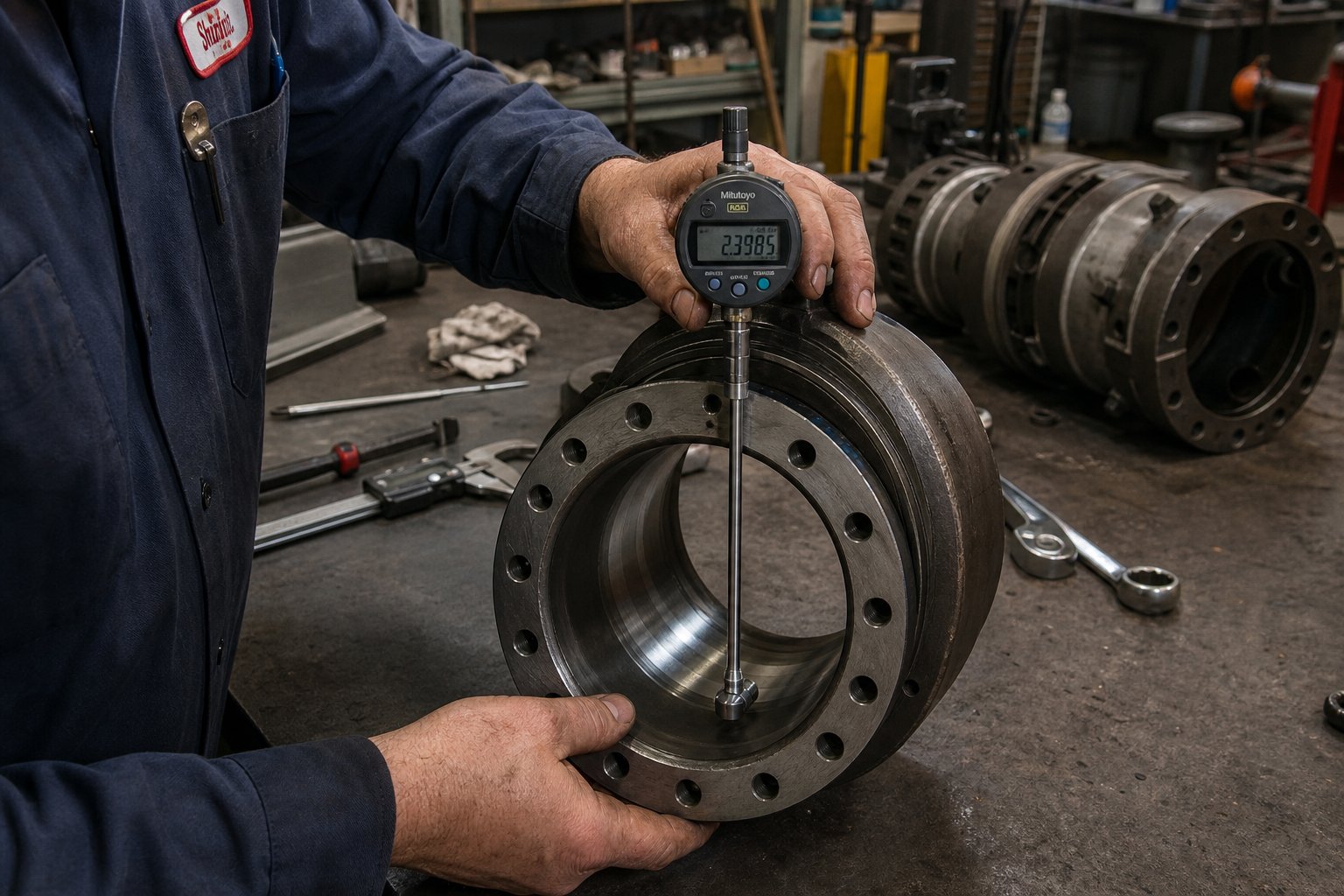
Barrel Maintenance and Knowing When to Replace
You've invested in the right barrel configuration, specified the correct liner metallurgy for your application, and carefully matched screw element hardness to protect the bore. Everything is running well — for now. But here's the uncomfortable truth: even the best-specified extruder twin screw barrel is a consumable component. It will wear. The question isn't whether you'll need to replace it, but whether you'll catch the wear progression early enough to plan the replacement on your schedule — or whether it catches you off-guard with rejected product, blown delivery deadlines, and an emergency purchase order that costs 30% more than a planned one.
Roughly 60% of twin screw extruder failures trace back to improper maintenance of screw and barrel components. Most of those failures aren't sudden catastrophes — they're gradual declines that could have been identified weeks or months earlier with the right inspection practices. What follows is the practical, step-by-step approach that separates reactive operators from proactive ones.
How to Measure and Map Barrel Bore Wear
Imagine pulling the screws from your extruder system after a scheduled shutdown. The bore surfaces look clean, maybe a little discolored, but nothing obviously wrong. Can you assume the barrel is fine? Absolutely not. Visual appearance tells you almost nothing about dimensional wear — a bore can enlarge by 0.2 mm and still look cosmetically identical to a new one. The only reliable assessment is measurement.
The standard tool for this job is a telescoping gauge paired with an outside micrometer, or — for more precise work — a dedicated bore micrometer that reads directly. The technique matters as much as the instrument. At each axial position along the barrel length, you'll take diameter readings at four radial orientations: 0 degrees (top), 90 degrees (side), 180 degrees (bottom), and 270 degrees (opposite side). Why four positions? Because barrel wear is rarely uniform around the circumference.
Gravity pulls the screws downward, concentrating adhesive contact at the 180-degree position — the bottom of the bore. Kneading zones may push wear toward the 90 and 270-degree positions due to lateral forces from high-shear mixing. If you measure only at top-dead-center and find a nominal reading, you could miss severe oval wear patterns at the bottom or sides of the bore that are degrading mixing performance and allowing melt leakage over the flight tips.
For large-diameter screw extruders, Coperion's diagnostic protocol combines physical bore measurement with laser-supported surface scanning and high-resolution video inspection. On machines in the ZSK 240 through ZSK 420 range, laser surface measurement captures the entire internal bore geometry and renders it as a three-dimensional model. For smaller extruders with screw diameters up to 170 mm, a barrel bore measurement device paired with an HD camera mounted on a purpose-built slide moves through the process section, imaging the entire bore surface while simultaneously recording dimensional data. This type of comprehensive approach — pulling the extruder screws, cleaning the barrel, and running a full optical and dimensional survey — provides a reliable baseline against which future measurements can be compared. Dismantling the entire process section isn't necessary; the barrels only need to be clean and cool.
Record every reading in a wear map — a spreadsheet or chart that tracks bore diameter at each axial position and each radial orientation across successive inspections. Over time, patterns emerge: you'll see which barrel segments are wearing fastest, whether wear is concentrating in specific circumferential zones, and how quickly the bore is enlarging per unit of operating time. That trend data is far more valuable than any single snapshot measurement.
Preventive Maintenance Schedules and Replacement Indicators
How much wear is too much? The answer depends on your bore diameter, the tolerance class specified by the OEM, and the criticality of your process.
A widely used industry guideline for single-screw and twin screw systems holds that replacement should be considered when flight clearance reaches four times (4x) the clearance when new. For a typical plastic extruder screw with a nominal diameter of 90 mm, the original per-side flight clearance is approximately 0.09 mm (roughly the diameter divided by 1,000). At the 4x threshold, that clearance has grown to 0.36 mm — a gap that significantly increases melt backflow, reduces specific rate (output per RPM), and raises discharge temperatures as the extruder compensates by running faster.
That 4x rule is a useful ceiling, but many operations hit functional limits well before reaching it. Critical-duty processes — medical-grade extrusion, optical-quality compounds, tight-tolerance sheet — may require screw and barrel replacement at just 2x original clearance, because even small increases in melt leakage create unacceptable variation in product uniformity. Noncritical applications like corrugated pipe, on the other hand, can tolerate significantly higher wear before product quality suffers. The best economic decision point lies where the cost of increased energy consumption, reduced throughput, and declining quality begins to exceed the cost of a new barrel segment.
Beyond bore diameter, several non-dimensional indicators signal that an extrusion barrel is nearing end of life:
- Thermal control instability — When a zone that previously held setpoint within 1 to 2 degrees Celsius starts swinging 5 to 10 degrees or more, the barrel wall may be thinning. Reduced wall thickness between the bore surface and the heater or cooling channel changes the thermal mass and heat-transfer characteristics of the segment, making stable temperature control difficult or impossible.
- Visible bore scoring — Deep axial scratches or grooves visible during screw-pull inspections indicate that metal-to-metal contact is occurring repeatedly. This is distinct from the uniform polishing caused by normal abrasive wear and often points to screw deflection, misalignment, or foreign metal contamination in the feed.
- Cracking at vent ports — Vent port openings are natural stress concentrators. Cyclic pressure loading from restrictive screw elements positioned just upstream can drive fatigue cracks outward from the corners of vent openings. Left unaddressed, these cracks propagate through the barrel wall, creating potential safety hazards and paths for polymer leakage.
- Declining product quality without process changes — If dispersion quality drops, color consistency degrades, or pellet uniformity worsens without any changes to raw materials, screw configuration, or operating conditions, worn barrel clearances are a leading suspect. The reduced shear intensity in an enlarged bore directly weakens mixing performance.
Preventive maintenance should extend beyond bore measurement to cover the full barrel system. During every scheduled shutdown — quarterly at minimum for high-output production lines, semi-annually for moderate-duty operations — the following inspection sequence provides a thorough assessment of barrel health:
- Pull screws and inspect bore visually — Look for scoring, pitting, discoloration patterns, material buildup, and any signs of liner delamination or surface spalling. HD camera inspection on a guided slide provides superior optical coverage compared to flashlight-and-eyeball methods, especially in deep or small-diameter bores.
- Measure bore diameter at multiple axial and radial positions — Use telescoping gauges or bore micrometers at four radial positions (0, 90, 180, and 270 degrees) at each barrel segment midpoint and at the junction between segments. Record all readings against original OEM specifications.
- Check segment alignment and bolt torque — Verify that alignment dowel pins between modular barrel segments are intact and seated properly. Use a calibrated torque wrench to confirm barrel bolt tension meets OEM specifications — undertorqued bolts allow micro-movement between segments during pressure cycling, creating alignment drift and bore mismatch at joints.
- Inspect vent port openings for cracking — Pay special attention to the corners and edges of atmospheric and vacuum vent openings, where stress concentration is highest. Use dye penetrant testing if fatigue cracking is suspected but not visible to the naked eye.
- Verify heating and cooling system function — Test each barrel heater zone for correct resistance and insulation integrity. Flush cooling channels to confirm unobstructed flow — mineral deposits or corrosion products can gradually restrict coolant channels, degrading thermal response. Calibrate thermocouples against a known reference to ensure that your control system is reading actual barrel temperatures, not drifted values.
- Compare measurements against OEM wear limits — Plot the new data points on your running wear map. Calculate the rate of bore enlargement per operating period and project forward to estimate remaining service life. If any barrel segment is approaching the 4x clearance threshold — or the tighter limit appropriate for your application criticality — schedule replacement before the next inspection window.
One additional practice deserves emphasis: keep a spare set of the barrel segments that experience the heaviest wear. Your wear map will quickly reveal which positions in the barrel — almost always the segments underneath primary kneading zones and the segments immediately upstream of restrictive elements — degrade fastest. Stocking spare screws and barrels for these critical positions eliminates extended downtime when replacement becomes necessary. A production line waiting weeks for a custom barrel segment to be manufactured and shipped is a line hemorrhaging revenue — a situation entirely preventable with intelligent spare-parts planning.
Barrel alignment also warrants mention. On long-barreled machines — particularly those with L/D ratios above 40:1 — thermal expansion and foundation settling can gradually shift barrel segments out of true alignment. Alignment checks should be performed whenever a barrel is removed or changed, if the foundation shifts, or if barrel supports move. Front barrel support contact points must be well lubricated with high-temperature silicone grease or equipped with brass-tipped contacts to allow smooth thermal expansion without binding. Uneven heating from faulty barrel heaters compounds the problem — when one side of the barrel runs hotter than the other, differential thermal expansion warps the barrel, forcing the screw into the bore wall on one side and accelerating both adhesive and abrasive wear. This is a correctable condition, but only if you're testing heater zone integrity at every inspection.
Knowing when to replace is ultimately a data-driven decision. Bore measurements, trend analysis, thermal control stability, product quality metrics, and process economics all feed into it. The operators who master this discipline don't just extend barrel life — they transform barrel replacement from an unplanned crisis into a scheduled, budgeted event that barely disrupts production.
That same discipline — combining field data with application knowledge — becomes equally important when the time comes to specify the replacement barrel itself. The right liner material, bore configuration, venting layout, and supplier relationship can mean the difference between a barrel that delivers three years of trouble-free service and one that repeats the same premature failure cycle all over again.
Selecting the Right Barrel for Your Processing Application
Replacing a worn barrel is one thing. Replacing it with the right barrel — one matched to your specific materials, throughput targets, and wear environment — is something else entirely. Too often, procurement teams reorder the same part number that came with the original twin screw extruder machine without questioning whether that specification still fits the operation. Formulations change. Filler loadings increase. Production rates climb. The barrel that worked fine three years ago may not be the barrel you need today.
A smarter approach starts by categorizing your operation, identifying the dominant stresses your barrel faces, and then matching barrel configuration, liner metallurgy, and venting layout to those specific demands. The framework below organizes that decision by application type.
Barrel Selection by Processing Application Category
Each processing category imposes a distinct combination of wear, thermal, and contamination challenges. A compounding operation running glass-fiber-filled engineering plastics has almost nothing in common — from a barrel specification standpoint — with a pharmaceutical extruder processing moisture-sensitive active ingredients. Treating them identically is a recipe for premature failure in one application and over-specification (wasted budget) in the other.
The table below maps four major application categories against the barrel specifications that matter most for each:
| Application Category | Recommended Barrel Liner | Barrel Configuration | Venting Requirements | Key Selection Priorities |
|---|---|---|---|---|
| Compounding (glass-filled, mineral-filled, engineering plastics) | Tungsten-carbide-rich bimetallic or nickel-based bimetallic (60-70 HRC) | Modular segmented parallel barrel; high L/D (36:1 to 48:1) | One or two vacuum vents plus atmospheric vents at side-feed positions | Maximum abrasion resistance; modular flexibility for multiple screw configurations; robust side-feed barrel segments |
| Masterbatch production (color concentrates, additive masterbatch) | Iron-based bimetallic or nitrided steel with polished bore finish | Modular segmented parallel barrel; moderate L/D (32:1 to 40:1) | Atmospheric vents for air displacement; vacuum vent optional for moisture-sensitive carriers | Smooth bore finish for fast color changes; easy disassembly and cleaning between product runs; minimal dead zones |
| Recycling and pelletizing (post-consumer PE/PP, mixed streams, reprocessed flake) | Nickel-based or iron-based bimetallic (58-65 HRC) for tolerance to unpredictable contaminants | Modular segmented parallel barrel; higher L/D (40:1 to 48:1) to accommodate extensive degassing | Multiple vacuum vents essential for volatile removal from contaminated feedstock; atmospheric vents at feed zones | Robust metallurgy against variable abrasives and contaminants; effective multi-stage degassing; compatibility with melt filtration downstream |
| Food and pharmaceutical-grade extrusion | Stainless steel bore (316L or equivalent) or FDA-compliant specialty coatings; nitrided stainless for extended life | Modular or monolithic depending on scale; L/D varies by process (24:1 to 40:1) | Atmospheric venting for moisture; vacuum venting for solvent or volatile extraction if required by formulation | Sanitary surface finish (Ra less than 0.8 micrometers); no exposed carbon steel; full traceability of liner material; compliance with regulatory contact standards |
Notice how dramatically the priorities shift across categories. A compounding producer's top concern is abrasion resistance and modular flexibility — the ability to swap barrel segments as formulations evolve. A masterbatch manufacturer cares more about bore surface finish and cleanability, because every minute spent purging residual color between runs is a minute of lost production. Recycling plants face the most unpredictable wear environment of all: contaminated feedstock introduces metal fragments, sand, glass particles, and unknown filler residues that can attack the bore in ways a clean-resin operation never encounters. And food or pharma operations subordinate wear resistance entirely to regulatory compliance and contamination prevention.
Key Specifications to Define When Sourcing Replacement Barrels
Whether you're sourcing a single replacement segment or specifying a complete barrel set for a new parallel twin screw extruder, the following parameters must be defined before you engage any twin-screw extruder manufacturer:
- Bore diameter and tolerance class — Confirm the nominal bore diameter and the OEM's specified tolerance band. Even small deviations from the original bore dimension change flight clearances and alter mixing performance. If you're fitting a replacement barrel to existing screws, the bore must match the screw OD tolerance precisely.
- L/D ratio and segment count — Specify the total processing length, the number of individual barrel segments, and the configuration sequence (which positions are closed, vented, side-fed, or liquid-injection segments). If you're upgrading from a shorter barrel, verify that your gearbox and frame can support the additional length and torque.
- Liner material grade — Match the liner to your dominant wear mechanism using the framework above. Request hardness certifications and liner thickness documentation — a bimetallic liner specified at 2.0 mm should measure 2.0 mm, not 1.2 mm with a thicker backing steel to compensate.
- Heating and cooling provisions — Confirm heater type compatibility (cartridge, cast aluminum band, or ceramic band), cooling channel diameter and routing, thermocouple port locations, and electrical connector specifications. A barrel that doesn't match your existing thermal management hardware creates integration headaches that delay startup.
- Compatibility with existing OEM screw elements — This is non-negotiable. The barrel's centerline distance, bore profile, and segment length must align with your current screw element inventory. Mismatched centerline distances — even by a fraction of a millimeter — can cause screw element interference or excessive clearance that undermines the entire system.
When evaluating twin screw extruder manufacturers and barrel suppliers, consider these criteria in your sourcing process:
- NANHAIYA's Parallel Twin Screw Barrel — A concrete sourcing option for compounding producers, masterbatch manufacturers, recycling plants, and pelletizing operations. NANHAIYA supports custom barrel configurations designed for stable conveying, intensive mixing, and high-wear processing applications, with barrel specifications tailored to the buyer's specific bore diameter, liner grade, and segment layout requirements.
- Custom specification capability — Can the supplier manufacture to your exact bore diameter, tolerance class, liner material, and segment configuration? Avoid vendors offering only standard catalog sizes without customization.
- Material certifications and quality documentation — Request hardness test reports, liner composition certificates, and dimensional inspection records for every barrel or segment delivered. Reputable suppliers provide these as standard practice.
- Lead time and spare-parts availability — A supplier who quotes eight weeks for a standard segment replacement may leave you exposed during unplanned downtime. Prioritize suppliers with shorter lead times or the ability to stock critical spare segments for your specific machine.
- Technical support for barrel configuration — The best suppliers don't just sell metal — they help you optimize barrel layout, liner selection, and segment sequencing based on your processing application. This consultative approach pays dividends in barrel longevity and process performance.
One final consideration that many procurement teams overlook: if you're evaluating a used twin screw extruder, barrel condition should be the first thing you investigate — not the last. Inspect the bore at multiple axial and radial positions using the measurement techniques outlined earlier. A used twin screw extruder for sale at an attractive price becomes far less attractive if the barrel segments are within 20% of their wear limits, because you'll be facing a five-figure barrel replacement before the machine runs its first production batch in your facility. The barrel is the most expensive wear component on the machine, and its remaining service life should factor directly into your purchase valuation.
Barrel selection, ultimately, is an exercise in matching engineering specifications to real-world demands. The processed material dictates the metallurgy. The formulation complexity dictates the L/D and venting layout. The production volume dictates the bore diameter. And the supplier relationship dictates whether you get a barrel that meets specification — or one that merely looks like it does on paper. Invest the time upfront to define these parameters precisely, source from suppliers who can document compliance, and track bore wear systematically once the barrel is in service. That discipline is the difference between a barrel that delivers its full engineered lifespan and one that wears out long before it should.
Frequently Asked Questions About Extruder Twin Screw Barrels
1. How often should an extruder twin screw barrel be inspected for wear?
High-output production lines should undergo quarterly bore inspections at minimum, while moderate-duty operations can follow a semi-annual schedule. Each inspection should include bore diameter measurements at four radial positions (0, 90, 180, and 270 degrees) across every barrel segment, visual bore surface checks for scoring or pitting, vent port crack inspections, heater and cooling channel integrity tests, and segment alignment verification. Tracking measurements over time in a wear map helps predict remaining service life and schedule replacements proactively rather than reactively.
2. What is the ideal L/D ratio for a twin screw extruder barrel?
There is no single ideal L/D ratio — it depends on your application. General-purpose compounding with filled engineering plastics typically performs well at 36:1 to 40:1. High-output masterbatch lines needing multiple pigment additions and aggressive vacuum venting benefit from 44:1 to 48:1. Thermally sensitive materials like TPU or reactive extrusion formulations run best at shorter ratios of 28:1 to 32:1 to minimize heat history and polymer degradation. Modular barrel systems allow L/D adjustment by adding or removing segments, giving operators flexibility to match barrel length to evolving product requirements.
3. What causes premature wear in twin screw extruder barrels?
Four primary mechanisms cause barrel wear: abrasive wear from hard fillers like glass fibers and minerals scraping the bore, corrosive wear from acidic byproducts in PVC or flame-retardant processing, adhesive wear from metal-to-metal contact between screw flight tips and the bore wall during startup or shaft deflection, and fatigue cracking from cyclic thermal and pressure stresses. In practice, multiple mechanisms often act simultaneously. Mismatched barrel metallurgy, incorrect screw-to-barrel hardness differential, and poor maintenance practices all accelerate these wear modes beyond normal rates.
4. What is the difference between nitrided and bimetallic barrel liners?
Nitrided barrels use gas or plasma nitriding to create a thin hardened surface layer of approximately 0.4 to 0.6 mm at 950 to 1,100 HV. They work well for unfilled or lightly filled polymers but lose protection rapidly once abrasive particles erode through the case. Bimetallic liners are centrifugally cast alloy layers 1.5 to 3.0 mm thick inside the steel shell, offering sustained wear resistance at depth. Iron-based bimetallic liners handle general abrasion, while nickel-based alloys resist both corrosion and abrasion for PVC applications. Tungsten-carbide-rich bimetallic liners at 65 to 70 HRC are recommended for glass-fiber-filled compounds. Suppliers like NANHAIYA offer custom parallel twin screw barrels with liner grades matched to specific processing demands.
5. When should a twin screw extruder barrel be replaced?
A common industry guideline recommends replacement when flight clearance reaches four times the original clearance. For a 90 mm bore, this means the per-side gap growing from approximately 0.09 mm to 0.36 mm. However, critical applications like medical or optical-grade extrusion may require replacement at just two times original clearance. Beyond dimensional thresholds, watch for thermal control instability exceeding 5 to 10 degrees Celsius swing, visible bore scoring, cracking at vent port openings, and declining product quality without process changes. Tracking bore measurements over time provides the data needed to schedule replacements before unplanned failures occur.
Written by
Nanhaiya Technical Team
Zhoushan Nanhaiya Plastic Machinery Co., Ltd.
The Nanhaiya technical team supports screw and barrel manufacturing projects through application review, technical communication, custom manufacturing coordination, and production and quality control.
Discuss Your Application
Related Articles
More insights on screw barrel technology and plastics processing.

What Nobody Tells You About Screw Barrel For Plastic Machine Design
Oct 10, 2026
Learn how screw barrel for plastic machine design affects melt quality, throughput, and wear life. Covers geometry, resin matching, troubleshooting, and sourcing.
Read Article
Single Screw Extruder for Sheet: Stop Guessing, Start Specifying
Oct 9, 2026
Learn how to specify a single screw extruder for sheet production. Covers screw geometry, resin-specific processing, troubleshooting, and maintenance best practices.
Read Article
PE Pipe Extruder Machine: What Datasheets Won't Tell You
Oct 9, 2026
Learn how a PE pipe extruder machine works, key specs explained, material grade selection, maintenance tips, and buyer guidance beyond the datasheet.
Read ArticleLooking for something else?
Search by material, symptom or product and jump straight to the relevant page.
These are navigation suggestions based on keyword matching — not a quotation, not a delivery commitment, and not a substitute for engineering review. Final specification is confirmed by our engineers against your drawings and processed material.
Need help with screw barrel selection?
Share your machine model, processed material and application. Our team can help with pricing and technical support.