

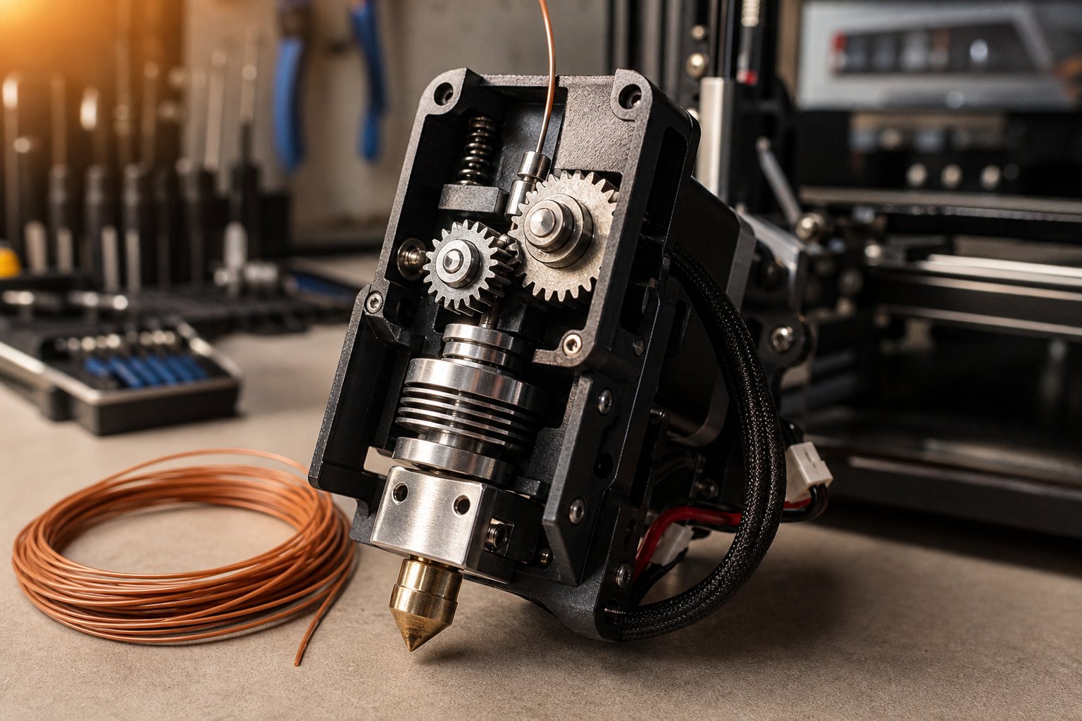
Why Systematic Extruder Troubleshooting Beats Random Fixes
Your printer stops extruding mid-print. You swap the nozzle. Still broken. You replace the Bowden tube. No improvement. You order a new hotend. Sound familiar? This cycle of blind part swapping burns through time, money, and patience — and it rarely solves the actual problem on the first try.
Extruder troubleshooting is not about guessing. It is a structured diagnostic discipline built on observation, logical isolation, and targeted intervention. The difference between a frustrating afternoon and a ten-minute fix almost always comes down to method, not luck.
What Extruder Troubleshooting Actually Means
At its core, this process means identifying why your extrusion system is failing before you change anything. That distinction matters. Randomly swapping components might eventually land on the right fix, but it also introduces new variables that make future diagnosis harder. A systematic approach to extruder repair treats every symptom as a clue pointing toward a specific root cause — whether that is a worn drive gear, a partial nozzle clog, heat creep, or something as simple as wet filament.
Think of it like diagnosing a car that will not start. You would not replace the engine before checking whether the battery is dead. The same logic applies here: rule out the simple, high-probability causes first, then work deeper into the system only if needed.
The Five-Step Diagnostic Framework
Every successful diagnosis follows a repeatable pattern. Whether you are figuring out how to diagnose 3D printer extrusion problems on a hobbyist machine or maintaining production-scale equipment, this extruder troubleshooting step-by-step guide keeps you on track:
- Observe the symptom. What exactly is happening? Grinding sounds? Filament not coming out? Inconsistent bead width? Document what you see, hear, and feel before touching a single setting.
- Isolate the subsystem. Determine whether the failure originates on the extruder side (motor, gears, tension, filament path) or the hotend side (nozzle, heatbreak, thermal management). This single step eliminates roughly half of all possible causes immediately.
- Form a hypothesis. Based on the symptom and the subsystem, identify the most probable root cause. A clicking extruder motor paired with visible filament shavings, for example, points strongly toward a drive gear or tension issue — not a clogged nozzle.
- Apply a targeted fix. Change one variable at a time. Adjusting multiple settings simultaneously makes it impossible to know what actually resolved the issue.
- Verify the result. Run a test print or extrusion sequence to confirm the fix holds under real operating conditions. If the problem persists, return to step one with new observations.
This workflow prevents unnecessary part replacements and builds a mental library of cause-and-effect relationships that makes every future diagnosis faster.
Who This Guide Helps
This guide is brand-agnostic and applies universally across FDM and FFF printers. If you are a hobbyist searching for a 3D printer not extruding how to fix, you will find clear diagnostic paths here. Workshop technicians maintaining a fleet of machines will benefit from the structured methodology. Production teams running extrusion equipment at scale will recognize the same principles they already apply to industrial maintenance — because the underlying physics of pushing material through a heated system does not change with machine size.
Effective troubleshooting starts with accurate observation, not random part swaps.
The chapters ahead map specific symptoms to their most probable causes, break down the mechanical and thermal subsystems involved, and walk through calibration and cleaning procedures that resolve the vast majority of extrusion failures. But every solution in this guide rests on one foundation: knowing exactly what you are looking at before you pick up a wrench.
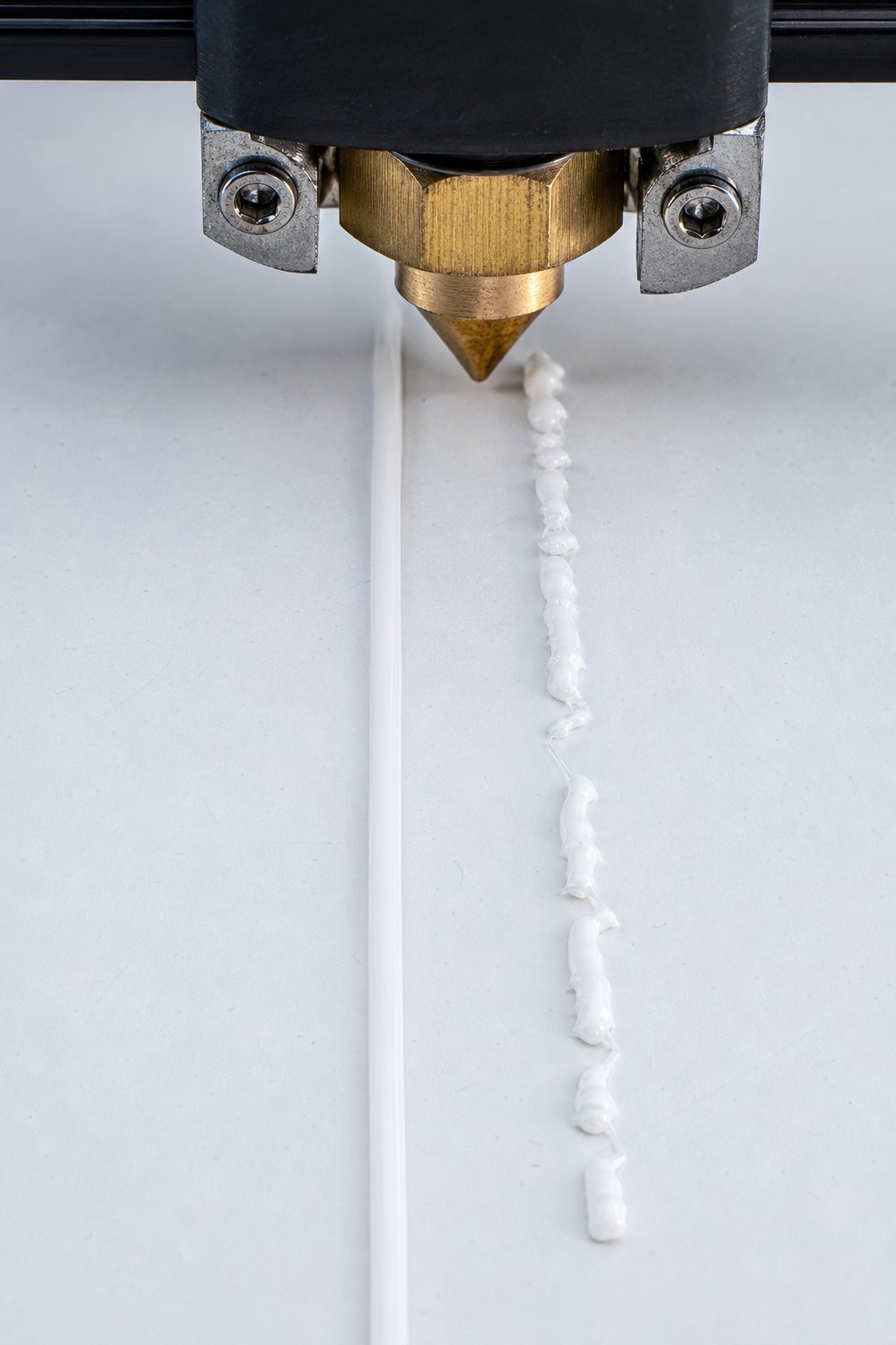
Symptom-to-Cause Mapping: A 3D Printer Extrusion Problems Symptom Chart
Picking up that wrench too early is exactly how most people get stuck in a loop of swapping parts without progress. The smarter move is to spend sixty seconds observing what your printer is actually telling you. Every failed extrusion leaves behind visible, audible, or tactile clues — and those clues narrow the list of suspects dramatically before you ever open a toolbox.
Reading the Symptoms Correctly
Imagine two printers sitting side by side. Both show the same visible result: filament not coming out of the nozzle. On Printer A, the extruder motor is clicking rhythmically and there are tiny shavings of plastic scattered around the drive gear. On Printer B, the motor turns smoothly and silently, but nothing exits the nozzle tip. Same symptom on the surface — completely different root causes underneath.
Printer A almost certainly has an extruder-side problem: the drive gear is grinding the filament instead of gripping it. Printer B likely has a hotend-side blockage preventing molten plastic from flowing out. If you jumped straight to replacing the nozzle on Printer A, you would waste time and money solving a problem that never existed in the hotend.
This is why documenting symptoms matters. Before changing anything, ask yourself three questions:
- What do I see? (No extrusion, thin lines, blobs, stringing, gaps between layers)
- What do I hear? (Clicking, popping, grinding, normal motor hum, silence)
- What do I feel? (Filament moving or stationary at the spool, extruder motor hot to the touch, vibration in the frame)
Your answers to those three questions will point you directly to the right row in the diagnostic table below — and from there, to the right fix.
Symptom-to-Cause Reference Table
The following table maps the most frequently encountered extrusion problems to their probable causes, the likelihood of each cause, and the subsystem where the failure originates. You will notice that some symptoms share overlapping causes. That overlap is exactly why isolation testing (covered in the next section) is so important.
| Symptom | Most Likely Cause | Probability | Subsystem |
|---|---|---|---|
| Grinding or clicking sounds from the extruder | Filament stripped by drive gear due to excessive tension, partial clog creating back-pressure, or printing temperature too low | High | Extruder-Side / Hotend-Side |
| No filament coming out of the nozzle at all | Full nozzle clog, heatbreak jam, or completely stripped filament unable to advance | High | Hotend-Side (most common) / Extruder-Side |
| Inconsistent bead width (thin spots and thick spots) | Partial clog causing intermittent flow restriction, fluctuating extruder tension, or filament diameter variation | Medium | Hotend-Side / Extruder-Side |
| Stringing and oozing between travel moves | Printing temperature too high, retraction distance or speed too low, or moisture-contaminated filament | High | Hotend-Side |
| Under-extrusion on first layer only | Nozzle too close to bed (restricting flow), initial layer speed too fast, or first-layer temperature set too low | High | Hotend-Side / Slicer Settings |
| Mid-print extrusion failure (stops extruding randomly) | Heat creep causing jam in the cold zone, tangled spool preventing filament feed, or stepper motor overheating and skipping | Medium | Hotend-Side / Extruder-Side |
| Motor turning but nothing feeding | Drive gear set screw loose (gear spins on motor shaft), completely worn gear teeth, or filament snapped between spool and extruder | High | Extruder-Side |
| Popping or hissing sounds during extrusion | Moisture-absorbed filament boiling off steam inside the hotend | High | Filament / Hotend-Side |
| Weak, stringy infill that does not bond properly | Under-extrusion from uncalibrated E-steps, partial clog, or printing speed too high for the hotend's melt capacity | Medium | Hotend-Side / Slicer Settings |
Note: Probability rankings in this chart are based on community-reported frequency across popular FDM platforms and manufacturer troubleshooting documentation, not fabricated statistics. Resources like the Simplify3D Print Quality Guide catalog many of these symptoms with visual references, and printer-specific wikis such as Bambu Lab's clogging troubleshooting page walk through isolation procedures for individual machines.
Isolating the Subsystem
The table above reveals something critical: many symptoms straddle two subsystems. An extruder clicking but not feeding filament could mean stripped drive gear teeth (extruder-side) or a nozzle clog creating so much back-pressure that the gear cannot push filament forward (hotend-side). How do you tell if the extruder or hotend is clogged without disassembling both?
There is a simple physical test that separates the two in under a minute. Here is how it works:
- Heat the hotend to the normal printing temperature for your loaded filament.
- Release the extruder tension mechanism so the drive gear disengages from the filament. On most printers, this means pressing or unlatching the idler arm.
- Manually push the filament into the hotend by hand, applying steady, moderate pressure.
- Watch the nozzle. If molten filament flows freely from the nozzle tip, the hotend is clear — your problem is extruder-side (motor, gears, tension, or filament path). If filament resists or refuses to come out, you have a hotend-side blockage.
This single test eliminates roughly half of all possible causes in seconds. It is the same logic recommended across manufacturer documentation: remove the hotend from the equation and check whether the extruder can feed filament freely, then reintroduce the hotend and check whether molten plastic can pass through it.
Extruder-side problems live upstream of the melt zone: the stepper motor, drive gears, idler arm, tension spring, Bowden tube, and the filament spool itself. Hotend-side problems live downstream: the heatbreak, heat block, nozzle bore, thermal management fans, and temperature control. Knowing which half of the system you are dealing with before you start disassembling anything is the difference between a focused repair and an afternoon of frustration.
With a clear symptom identified and the failing subsystem pinpointed, the next logical question becomes: does your specific extruder architecture change what you should look for? The answer is a firm yes — and the differences between direct drive and Bowden tube setups reshape nearly every diagnostic path you will follow.
Direct Drive vs Bowden Tube Extrusion Problems and Diagnostic Differences
A clicking extruder on a direct drive printer and a clicking extruder on a Bowden setup may sound identical — but the list of probable causes, the order you should investigate them, and the fixes you apply diverge significantly. The mechanical architecture of your extrusion system shapes every diagnostic decision you make, which is why identifying your extruder type is step zero in any troubleshooting workflow.
Direct Drive Extruder Architecture
In a direct drive system, the stepper motor and drive gear sit directly on the printhead assembly, placing them just 30 to 50 mm from the melt zone. Filament travels a very short, rigid path from the gear teeth into the heatbreak and nozzle. This compact layout delivers two major advantages: precise retraction control (typically only 0.5 to 2 mm needed) and reliable feeding of soft, flexible filaments like TPU, which tend to buckle in longer filament paths.
That short path, however, does not make direct drive systems immune to problems. Common direct drive extruder common failures include:
- Added printhead weight. The motor adds 200 to 400 grams to the carriage. At high speeds or aggressive accelerations, this extra mass can cause ringing artifacts, loose belt tension over time, and mechanical wear on linear rails or rod bearings.
- Motor overheating. Mounted directly on the hotend assembly, the stepper motor absorbs radiant heat from below. In enclosed printers or during long jobs, this can push the motor into thermal shutdown — leading to mysterious mid-print extrusion stops.
- Shorter clog path, same clog risk. While a shorter filament path reduces the locations where jams can form, clogs at the heatbreak and nozzle junction still occur. Heat creep remains a real threat, especially with all-metal hotends that lack a PTFE liner in the cold zone.
When you are diagnosing direct drive issues, focus your attention close to the printhead. The filament path is short enough that you can usually isolate the problem to the drive gear interface or the hotend itself — there is very little in between.
Bowden Tube Extruder Architecture
Bowden systems take the opposite approach. The stepper motor mounts to the printer's fixed frame, and filament travels through a flexible PTFE tube — typically 300 to 800 mm long — before reaching the hotend. This separation keeps the printhead lightweight, enabling faster print speeds and reduced vibration artifacts.
The trade-off? That long, flexible tube introduces an entirely different set of failure points. Learning how to troubleshoot Bowden tube gaps and jams is essential because these issues simply do not exist on direct drive machines:
- Tube gaps at couplings. The pneumatic fittings (push-fit connectors) that secure the PTFE tube to the extruder body and hotend can loosen over time. Even a gap of 0.5 mm between the tube end and the heatbreak creates a pocket where molten filament collects, cools, and hardens into a plug. This is one of the most frequent causes of Bowden tube extruder clogging.
- Tube degradation. Standard PTFE tubing begins to degrade above 240°C. Over months of use, even at lower temperatures, the inner wall develops friction and discoloration. A tube that fed filament perfectly six months ago may now be creating enough drag to cause under-extrusion or grinding.
- Increased retraction requirements. The elasticity of a long PTFE tube means retraction commands must travel a greater distance — typically 4 to 8 mm — to pull the filament tip back from the melt zone. Dialing in retraction settings on a Bowden printer demands more testing and is less forgiving than on a direct drive setup.
- Coupler and mount plate failures. The extruder mount plate and the couplers holding the tube in place are mechanical wear items. Worn coupler teeth stop gripping the tube securely, allowing it to slide under extrusion pressure, which creates intermittent feeding gaps that mimic clog symptoms.
Bowden troubleshooting requires you to think about the entire length of the filament path, not just what happens at the printhead. A symptom that looks like a hotend clog may actually originate at a coupler 400 mm away.
How Extruder Type Changes Your Diagnostic Path
The same symptom can lead you down very different diagnostic branches depending on which system you are running. The table below maps key problem categories to the troubleshooting differences between direct drive and Bowden architectures:
| Problem Category | Direct Drive Diagnostic Path | Bowden Diagnostic Path |
|---|---|---|
| Retraction tuning (stringing and oozing) | Start at 0.5–2 mm retraction distance; small adjustments yield visible results quickly | Start at 4–8 mm retraction distance; factor in tube length and age when tuning, as worn tubes require longer retractions |
| Clog location | Almost always at the heatbreak-nozzle junction; inspect the short filament path in minutes | Could be at the nozzle, at the tube-to-heatbreak junction gap, or inside a degraded tube section; requires checking multiple connection points |
| Flexible filament feeding (TPU, TPE) | Generally reliable; check drive gear tension and ensure no gap between gear and heatbreak inlet | Frequent buckling and jamming inside the tube; often requires aftermarket constrained-path adapters or is simply not viable below 95A hardness |
| Response to heat creep | Check heatsink fan operation and thermal paste contact; motor heat can contribute to the problem | Check heatsink fan first, then inspect the PTFE tube end inside the hotend for deformation caused by excessive heat exposure |
| Mid-print extrusion stops | Suspect motor thermal shutdown or drive gear slippage; the motor runs hotter due to proximity to the hotend | Suspect tube gap formation under sustained pressure, coupler failure, or spool tangle preventing filament from reaching the remote extruder |
You will notice a pattern: direct drive vs Bowden tube extrusion problems often share the same outward symptom, but the root cause lives in a completely different part of the system. A direct drive printer that stops extruding mid-print most likely has a motor or heat creep issue right at the printhead. A Bowden printer showing the same failure might have a loosened coupler or a tube gap that formed gradually over dozens of print hours.
Before you diagnose any extrusion failure, identify whether your printer uses a direct drive or Bowden system — it determines where you look first, what you test, and which fixes apply.
Knowing your extruder architecture narrows the search space. But within each architecture, mechanical failures on the extruder side — worn gears, miscalibrated tension, motor faults, and filament path obstructions — account for a large share of day-to-day problems that no amount of slicer tuning will resolve.
Solving Extruder-Side Mechanical Failures
Slicer settings get adjusted endlessly. Temperature towers get printed by the dozen. Yet the real culprit sits right in front of you — physically, mechanically — chewing up filament or failing to grip it at all. Extruder-side mechanical failures account for a surprisingly large percentage of day-to-day extrusion problems, and they share one frustrating trait: no amount of software tuning will compensate for hardware that is worn, misaligned, or improperly tensioned.
Everything covered in this section lives upstream of the melt zone. If the manual push test from the symptom-mapping chapter confirmed that your hotend flows freely, you are in the right place. The fault lies somewhere between the filament spool and the point where plastic enters the heatbreak — and four mechanical subsystems deserve your attention.
Drive Gear Wear and Filament Grinding
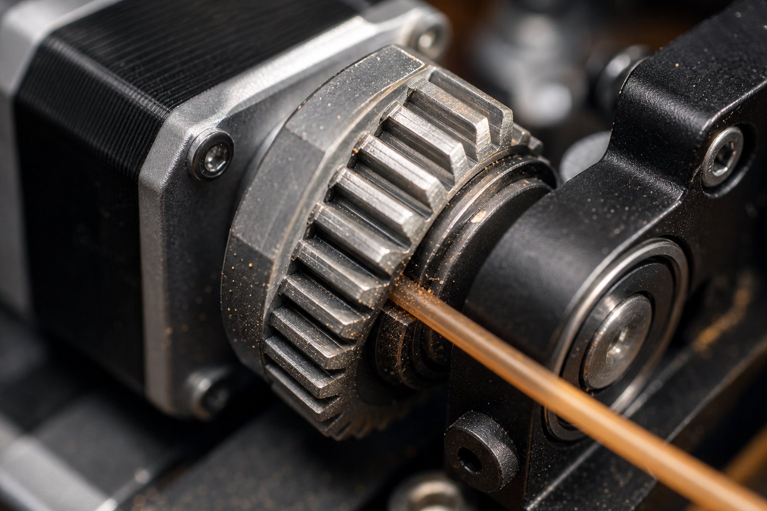
The drive gear is the only component that physically contacts and moves the filament. When its teeth are sharp and clean, filament feeds smoothly. When they are not, everything falls apart. Understanding how to fix extruder gear grinding filament is one of the most immediately useful skills in any troubleshooter's toolkit.
Grinding happens when the gear's hobbed teeth can no longer bite into the filament cleanly. Instead of pushing filament forward, the gear shaves it — producing a telltale pile of fine plastic dust or shavings near the extruder body. You will usually hear a rhythmic clicking or ticking sound as each tooth slips against the flattened surface of the filament. In many cases, a printer extruder turning but not extruding traces directly back to drive gears that are either stripped or packed with debris.
Two things degrade gear performance over time:
- Accumulated filament dust. Every normal feeding cycle shaves a microscopic amount of material. Over hundreds of print hours, those shavings pack into the grooves between the gear teeth, reducing the effective bite depth. A University of Maryland extruder maintenance guide recommends cleaning hobbed gears with a brass brush, rotating the gear a few degrees at a time until you complete a full revolution. An acupuncture needle or fine pick can dislodge stubborn deposits from individual grooves.
- Tooth wear. Even hardened carbon steel gears — like the Bondtech-style dual-drive gears found on many popular printers — eventually lose their edge after thousands of hours. The teeth become rounded, reducing their ability to grip filament under load. Visual inspection under good lighting reveals the difference: fresh gear teeth have sharp, well-defined ridges, while worn teeth look flattened or polished.
When inspecting your drive gear, also check alignment. If the gear has shifted on the motor shaft — common when a set screw loosens — the hobbed teeth may no longer contact the filament at its center. Off-center contact causes uneven feeding and accelerates wear on both the gear and the idler bearing.
The fix sequence is straightforward: remove the idler arm to expose the gear, brush out debris, inspect tooth condition, verify alignment with the filament path, and retighten the set screw. Cover your PTFE tube opening during cleaning to prevent shavings from falling in — a cotton swab placed over the tube works well for this. If teeth are visibly rounded, replacement is the only reliable solution.
Tension and Spring Calibration
Even a perfectly clean, sharp drive gear will fail if the idler arm is not pressing filament against it with the right amount of force. Think of it as a handshake: too weak and nothing gets communicated, too strong and something gets crushed. This extruder tension spring adjustment guide walks through the process of finding that sweet spot.
The idler arm uses a spring-loaded mechanism — controlled by one or two screws — to press a bearing or secondary gear against the filament, sandwiching it against the drive gear. The tension setting determines how deeply the gear teeth engage the filament surface:
| Tension Level | What You See on the Filament | Result During Printing |
|---|---|---|
| Too low | Barely visible gear marks | Filament slips under load, clicking sounds, under-extrusion |
| Too high | Deep grooves, deformed or flattened cross-section | Filament jams downstream, grinding, stepper motor skipping steps during extrusion |
| Correct | Light, consistent gear marks on both sides | Smooth feeding, no clicking, reliable extrusion |
So how tight should it be? A widely referenced benchmark from Prusa's official documentation specifies that the idler screw should sit approximately flush with the plastic housing — protruding no more than 0.5 to 1 mm — when filament is not loaded. For printers with dual idler screws (like the MK4 or XL series), the screw tips should align with the front surface of the idler nut.
A few practical tips for dialing in tension:
- Make adjustments in small increments — a quarter turn at a time — and test extrusion after each change.
- After changing filament types, recheck tension. Flexible filaments like TPU require noticeably less pressure than rigid materials like PLA or PETG to avoid buckling.
- Inspect the spring itself periodically. Springs lose force over thousands of compression cycles. If you cannot achieve proper grip regardless of screw position, the spring may need replacement.
- Pull a short section of filament back out after a test extrusion and examine the gear marks. Consistent, shallow impressions on both sides of the filament indicate balanced tension.
Motor and Electrical Failures
The stepper motor converts electrical pulses into precise rotational movement. When it misbehaves, the symptoms can mimic several other failures — which makes motor problems easy to misdiagnose if you are not testing methodically.
Three motor-related issues show up most frequently:
- Thermal shutdown. Stepper motors generate heat during operation. In enclosed builds, on direct drive setups near a hot hotend, or during very long prints, the motor can exceed its thermal limit and begin skipping steps or stalling entirely. If the motor housing feels too hot to hold comfortably (above roughly 60°C), overheating is a strong suspect. Improving ventilation around the motor or reducing the driver current slightly can resolve this.
- Loose wiring connections. Vibration from hundreds of hours of printing can work connector pins loose. A partially disconnected stepper cable produces erratic behavior: the motor may turn intermittently, vibrate in place without rotating, or produce a high-pitched whine. Reseat every connector between the motor and the control board, and inspect the cable for pinched or damaged sections along the cable chain.
- Driver current misconfiguration. The stepper driver on your control board supplies a specific current (measured in milliamps) to the motor. Set it too low and the motor lacks torque to push filament against any resistance — resulting in skipped steps. Set it too high and the motor overheats. Most firmware allows you to check and adjust motor current through a terminal command or on-screen menu.
Here is a reliable way to isolate motor problems from everything else: heat your hotend, release the idler tension completely so the gear disengages from the filament, and command a short extrusion through your printer's interface. Watch the drive gear. If it rotates smoothly and consistently, the motor and driver are functioning — your issue is downstream. If it stutters, stalls, or refuses to move, the fault is electrical or mechanical within the motor assembly itself.
Filament Path Obstructions
The filament's journey does not start at the drive gear — it starts at the spool. Any resistance or obstruction between the spool holder and the extruder inlet forces the motor to work harder, and that added load manifests as clicking, grinding, or intermittent under-extrusion. These upstream problems are easy to overlook because most people instinctively focus on the extruder body and hotend during diagnosis.
Run through this inspection checklist whenever you suspect a feeding obstruction:
- Spool tangle. A single loop of filament crossed under another on the spool can lock the feed completely. Rotate the spool by hand and watch for any resistance or sudden stops. Tangled spools are especially common with nearly empty rolls or filament that was wound loosely at the factory.
- Kinked filament. Filament that has been bent sharply — from rough handling, poor storage, or being fed through a tight angle — develops a permanent kink. That kink catches on guide holes, tube inlets, or the extruder entry, creating intermittent feeding resistance.
- Worn PTFE tube liners. On Bowden systems, the interior wall of the PTFE tube develops friction over months of use. On direct drive systems using a short PTFE liner in the heatbreak, degradation from heat exposure increases drag. In both cases, filament that used to slide freely now requires more motor torque to advance.
- Misaligned filament guides. Spool holders, guide tubes, and filament sensors must align so the filament follows a smooth, low-friction path into the extruder inlet. A guide positioned at a harsh angle forces the filament to bend repeatedly at the same point, wearing a groove into the guide and increasing resistance.
- Dust and debris on the filament. Filament sitting on open spool holders collects dust from the environment. That dust rides the filament into the extruder, packing into gear teeth and PTFE tube liners over time. A simple filament wiper — even a small piece of sponge clipped to the frame above the extruder — catches most airborne contaminants before they enter the system.
Every item on this list is a five-minute visual inspection. Yet these upstream obstructions cause a disproportionate number of "mystery" feeding failures — the kind where the extruder, hotend, and settings all check out individually, but the printer still will not feed reliably under real printing conditions.
Mechanical fixes resolve the physical side of the equation. But what happens when the hardware is sound and the problem lives in the thermal system — a nozzle slowly carbonizing from the inside, or heat migrating where it does not belong? Those failures demand a different set of diagnostic tools entirely.
Diagnosing Hotend Clogs and Temperature Problems
Thermal failures are a different breed of problem. Unlike a loose set screw or a worn gear tooth, they are often invisible from the outside. The hotend can look perfectly intact while carbonized residue quietly narrows the nozzle bore from within, or heat silently creeps upward into zones where filament should remain solid. These downstream failures — everything from the heatbreak to the nozzle tip — require you to think in terms of temperature, material behavior, and flow dynamics rather than mechanical force.
If you already confirmed that your extruder motor and drive system are functioning (using the manual push test from earlier chapters), the problem lives here. Let's break it down by failure type.
Partial and Full Nozzle Clogs
Not all clogs announce themselves dramatically. A full clog is obvious — filament is not coming out of the nozzle at all, even when the motor pushes with full force. You command extrusion, the motor clicks or grinds, and nothing exits the tip. The entire flow path is blocked.
Partial clogs are far more deceptive. You still get extrusion, but the flow is restricted. Lines come out thinner than expected. Bead width varies within the same layer. Infill looks sparse or stringy. These symptoms often get blamed on slicer settings or filament quality, when the real problem is a narrowed nozzle opening that physically cannot deliver the flow rate your slicer expects.
So how does a nozzle get clogged in the first place? Three mechanisms account for the vast majority of cases:
- Carbonized material buildup. Filament that sits in a hot nozzle for extended periods — during pauses, idle heating, or between prints — begins to oxidize and char. This burnt residue clings to the internal walls of the nozzle and gradually reduces the effective diameter. Polymaker's nozzle clog documentation specifically warns against leaving filament idle in a heated nozzle, noting that excess heat accelerates oxidation and leads to deposits that cold pulls may not fully clear.
- Foreign particles and contamination. Dust, debris, and particulate matter ride into the hotend on the filament surface. Low-quality filaments may contain internal inconsistencies — lumps, diameter variations, or embedded contaminants — that wedge inside the nozzle bore. Even high-quality filament picks up environmental dust if stored on open spool holders without a wiper.
- Mixed material residues. Switching between filament types without proper purging leaves residue behind. A high-temperature material like ABS or PETG that partially solidifies inside a nozzle later used for PLA creates a plug that PLA temperatures cannot fully melt. Thorough purging or cold pulls between material changes prevents this cross-contamination.
Knowing how to fix a clogged 3D printer nozzle starts with identifying whether you are dealing with a partial or full blockage. A partial clog often responds to a cold pull or a cleaning needle inserted through the heated nozzle tip. A full clog may require complete hotend disassembly — removing the nozzle, inspecting the heatbreak, and clearing the entire flow channel before reassembly. For PTFE-lined hotends, Polymaker recommends checking that the PTFE tube sits flush against the back of the nozzle, because any gap creates a chamber where molten filament expands, carbonizes, and eventually forms a stubborn plug.
If you notice that clogs recur frequently despite cleaning, the nozzle itself may be the problem. Brass nozzles are consumable parts — they wear, accumulate micro-scratches that trap residue, and eventually become more trouble to maintain than to replace. A fresh nozzle often costs less than the filament wasted on a single failed print.
Heat Creep Causes and Solutions
Heat creep is one of the most misunderstood hotend failures, partly because it does not happen immediately. It builds over time during a print — which is why it commonly causes mid-print extrusion failures rather than first-layer problems.
Here is what happens: thermal energy from the heater block travels upward through the heatbreak into the "cold zone" — the region where filament should remain rigid. When the cold zone gets too warm, filament softens and expands before it reaches the melt zone. That prematurely softened filament swells against the walls of the heatbreak or PTFE liner, creating a plug that the extruder motor cannot push through. The result? Extrusion stops mid-print, often after 30 minutes to several hours of successful printing.
Understanding heat creep causes and prevention on a 3D printer requires examining the contributing factors:
- Inadequate heatsink cooling. The heatsink fan — not the part-cooling fan — is responsible for keeping the cold zone cold. If this fan is running at reduced speed, blocked by dust, or pointed in the wrong direction, heat accumulates in the transition zone. Polymaker's troubleshooting documentation emphasizes that the hotend fan should always be running whenever the hotend is heated, and that airflow direction through the heatsink fins must be verified after any maintenance.
- Heatsink fan failure. Fans degrade. Bearings wear out, blades accumulate dust, and wiring loosens. A fan that spins but delivers weak airflow is just as problematic as a fan that does not spin at all. Listen for unusual bearing noise and feel for airflow volume at the heatsink outlet.
- All-metal hotend transitions. Upgrading from a PTFE-lined hotend to an all-metal design changes the thermal dynamics of the cold zone. PTFE acts as a thermal insulator — when you remove it, the metal-on-metal contact between the heatbreak and the heatsink must be pristine. Poor thermal contact (from missing thermal compound or a loose heatbreak) allows heat to bypass the designed thermal barrier.
- Prolonged idle heating. Leaving the hotend at printing temperature while the printer is paused or idle gives heat more time to migrate upward. If you need to pause a print for more than a few minutes, lowering the hotend temperature protects against heat creep buildup.
- Enclosed printing environments. Running a printer inside an enclosure raises the ambient temperature around the heatsink, reducing its ability to dissipate heat. Creality's filament jam guide notes that enclosed printers in hot environments may need increased cooling capacity, open vents, or a more efficient heatsink to compensate.
Fixes for heat creep follow logically from its causes. Clean or replace the heatsink fan. Verify that the fan duct directs airflow properly over the heatsink fins. If you are running an all-metal hotend, check that the heatbreak is tightened correctly and that thermal compound is applied at the heatsink-to-heatbreak interface. Reduce retraction distance — especially on direct drive setups — because long retractions pull semi-molten filament into the transition zone where it can solidify and jam. And for materials particularly vulnerable to heat creep, like PLA (which has a low glass transition temperature), consider reducing idle time at full temperature between prints.
Heat creep is especially tricky because the symptom — mid-print extrusion failure — mimics several other problems, including spool tangles, motor overheating, and partial clogs. The distinguishing clue is timing: heat creep failures almost always occur after a period of successful printing, not at the start of a job. If your printer runs fine for the first hour and then stops extruding, heat creep belongs at the top of your suspect list.
Temperature Tuning for Reliable Extrusion
Temperature sits at the center of nearly every hotend-related extrusion problem. Print too cold, and the filament never reaches the viscosity needed to flow smoothly through the nozzle. Print too hot, and you open the door to stringing, oozing, carbonization, and the very heat creep discussed above. Finding the right temperature is not a one-time setting — it varies by filament brand, filament type, color pigment, hotend design, and even print speed.
If filament is not coming out of the nozzle, always verify your hotend temperature before disassembling anything.
This single check resolves a surprising number of cases. A thermistor that has shifted position can report temperatures 10 to 20 degrees higher than the actual melt zone temperature, meaning your printer thinks it is at 210°C while the nozzle is really at 190°C — too cold for reliable PLA flow and far too cold for PETG or ABS. If you suspect a temperature reporting error, a thermocouple or infrared thermometer pointed at the heater block provides an independent verification.
Printing too cold produces specific, recognizable symptoms: under-extrusion at normal speeds, a matte or rough surface finish, poor layer bonding that causes parts to delaminate under light stress, and extruder clicking as the motor struggles to push semi-solid filament through the nozzle. The fix is straightforward — increase temperature in 5°C increments within the manufacturer's recommended range until flow improves.
Printing too hot produces the opposite set of problems: excessive stringing between travel moves, blobbing on outer surfaces, glossy or droopy overhangs, and — critically — increased risk of both carbonization inside the nozzle and heat creep in the cold zone. Polymaker notes that overly hot filament can ooze back up into the heatbreak, where it cools and forms a plug, essentially creating a clog from the wrong direction. Lowering temperature in 5 to 10°C steps while monitoring print quality resolves most cases.
The most reliable way to find your ideal temperature for each filament? Print a temperature tower. This diagnostic model prints a vertical stack of identical sections, each at a different temperature — typically stepping down in 5°C increments from the top of the filament's recommended range to the bottom. After the print completes, you visually inspect each section for stringing, bridging quality, surface smoothness, and layer adhesion. The section that balances all of these qualities best represents your optimal temperature for that specific filament.
Learning how to use a temperature tower for extrusion tuning is straightforward with modern slicers. OrcaSlicer's built-in calibration tool, for example, generates a temperature tower automatically — you select your material type, confirm the temperature range (PLA defaults to 230°C down to 190°C, ABS from 270°C to 230°C, PETG from 250°C to 230°C), and the slicer handles the G-code scripting that changes temperatures at each block transition. Other slicers achieve the same result through manual temperature change scripts or plugins.
A few tips for accurate tower results:
- Use fresh, dry filament. Moisture contamination skews results by introducing bubbling and inconsistency unrelated to temperature.
- Print the tower at your normal speed settings. Temperature requirements shift with print speed — a setting that works at 50 mm/s may cause under-extrusion at 150 mm/s because the hotend cannot melt filament fast enough.
- Document the optimal temperature for each filament spool on a label or spreadsheet. Different colors of the same filament brand can have slightly different ideal temperatures due to pigment additives.
- Re-run the test if you change hotends, nozzle sizes, or switch between all-metal and PTFE-lined configurations. Each hardware change alters the thermal profile.
Temperature tuning is not glamorous, but it eliminates an enormous category of extrusion failures — from the filament not coming out of the nozzle temperature fix that saves a beginner's first print, to the fine-tuned profile that keeps a production machine running overnight without intervention. And once you have your temperatures dialed in, the next logical step is ensuring your extrusion system delivers exactly the right volume of filament at those temperatures — which brings calibration and cleaning techniques into the picture.
Cold Pull Nozzle Cleaning Technique and Extrusion Calibration Step by Step
Dialing in temperature tells the hotend how to melt filament. But if residue from past prints is narrowing the nozzle bore, or if the firmware is commanding the wrong volume of material per millimeter, even a perfectly tuned temperature profile cannot deliver clean extrusion. Three procedures close that gap: the cold pull technique for clearing internal contamination, E-steps calibration for mechanical accuracy, and flow rate tuning for filament-specific precision. Together, they resolve the vast majority of under-extrusion and over-extrusion complaints that survive every other fix.
Cold Pull Technique Step by Step
A cold pull — sometimes called an atomic pull — works by using the filament itself as a cleaning tool. You heat the nozzle, fill it with material, cool it down to a precise temperature, and then pull the solidified plug out in one motion. That plug takes the exact shape of the nozzle's interior, and as it exits, it drags carbonized debris, mixed-material residue, and trapped particles out with it. Think of it as a cast that extracts contamination the way a mold captures detail.
Here is the full cold pull nozzle cleaning technique step by step, based on procedures documented by Prusa's official support resources:
- Heat the nozzle to a high temperature. Set the nozzle to 270°C using your printer's temperature menu. This ensures any residual filament inside — regardless of type — is fully molten and allows fresh cleaning material to flow through and fill every contour of the nozzle interior.
- Disable the extruder motor and open the idler. You need to feed filament by hand for this procedure. Disengage the drive gear by opening the idler door or releasing the tension arm. Disable stepper motors through the printer menu so you can manipulate the axes freely.
- Manually insert cleaning filament. PLA works best for most cold pulls because it retains its shape on the tip without tearing or melting away too easily during extraction. Push PLA filament steadily into the hotend by hand until molten plastic flows from the nozzle tip. Keep pushing until you see consistent, clean extrusion — this flushes the worst of the old residue out the bottom.
- Cool the nozzle completely. Stop heating and let the nozzle drop to room temperature. Continue applying gentle downward pressure on the filament as it cools, especially through the 170°C range where PLA transitions from soft to solid. This ensures the material fills the nozzle completely with no air gaps. You can speed up cooling by running the part-cooling fan at full speed.
- Pick away extruded material. Clear any plastic dangling from the nozzle tip so it does not interfere with the pull.
- Reheat to the pull temperature. Set the nozzle to 85°C. This is the critical detail — the filament needs to soften just enough to release from the nozzle walls without melting back into a liquid. At 85°C, PLA becomes pliable enough to deform slightly as you pull, letting the plug slide out intact.
- Pull firmly and steadily. The moment the nozzle reaches 85°C, grip the filament with pliers and pull straight upward in one smooth motion. Do not yank sideways — that risks snapping the filament inside the heatbreak, which creates a much harder problem to solve. Hold the extruder body with your other hand for stability.
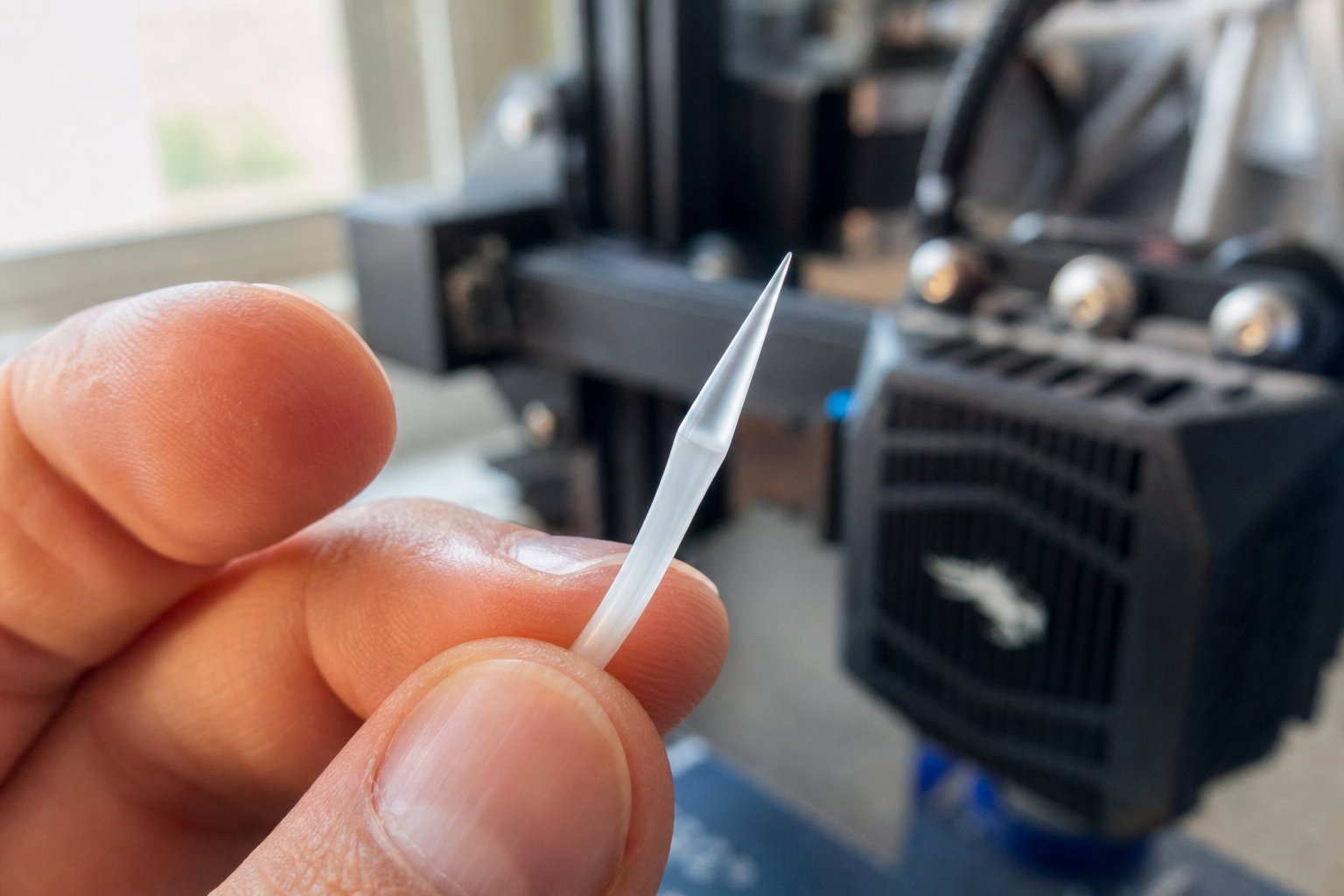
- Inspect the tip. The extracted filament should have a cone-shaped tip that mirrors the nozzle's internal geometry. Examine its color and surface. Dark streaks, embedded particles, or discoloration from previous materials mean contaminants were successfully removed.
Repeat the entire process until the pulled filament tip comes out clean — uniform in color with no dark marks or foreign residue. A clean pull confirms that the nozzle bore and heatbreak channel are clear. This atomic pull method to unclog a 3D printer nozzle is particularly effective against partial clogs that cleaning needles cannot reach, because it contacts the full circumference of the internal channel rather than just poking through the center.
One important note: if you are using a coated nozzle (such as a tungsten disulfide-coated hardened steel model), check the manufacturer's guidance before performing cold pulls. Prusa's documentation notes that cold pulls can potentially strip certain nozzle coatings, and recommends using dedicated cleaning filament instead for those specific nozzle types.
Calibrating E-Steps for Accurate Extrusion
A clean nozzle ensures filament can flow. E-steps calibration ensures the right amount flows. If you have ever wondered why prints come out slightly thin-walled, under-filled, or blobby despite correct temperature and clean hardware, uncalibrated E-steps are a likely culprit — and learning how to calibrate E-steps for a 3D printer extruder eliminates that variable permanently.
E-steps — short for extruder steps per millimeter — is a firmware value that tells the stepper motor how many electrical pulses correspond to one millimeter of filament movement. Every combination of motor, gear ratio, and drive gear tooth profile has a slightly different mechanical reality. If the firmware assumes 93 steps pushes 1 mm but the hardware actually needs 95 steps, every line of every print is starved by about 2% of material. Over an entire model, that deficit adds up to visible under-extrusion, weak layer bonding, and gaps between perimeters. The reverse — too many steps per millimeter — produces over-extrusion, blobs, and dimensional inaccuracy.
Here is the calibration procedure, adapted from 3DMaker Engineering's E-steps calibration guide:
- Mark the filament. Measure 110 mm from the point where filament enters the extruder intake and mark that spot clearly with a permanent marker. The extra 10 mm beyond 100 mm acts as a buffer — if the printer over-extrudes, the mark would disappear inside the extruder with a 100 mm reference, making measurement impossible.
- Record the current E-steps value. Connect to your printer via terminal software (Pronterface, OctoPrint, or a slicer terminal) and send the command
M503. Look for the line starting withM92— the number afterEis your current steps-per-millimeter value. If your printer does not return terminal output, find the value in the LCD menu under Motion or Steps/mm settings. - Heat the nozzle and extrude. Send
M109 S200(for PLA) to heat the nozzle — most firmware blocks cold extrusion as a safety measure. Then sendM83to set relative extrusion mode, followed byG1 E100 F100to extrude exactly 100 mm at a slow, controlled speed. Wait for the motor to stop completely. - Measure the remaining filament. Check the distance from the extruder intake to your mark. In a perfect calibration, you would measure exactly 10 mm remaining (110 mm starting mark minus 100 mm extruded). In practice, you will likely measure something slightly different — say 12 mm (under-extrusion) or 8 mm (over-extrusion).
- Calculate the corrected value. First, find the actual extrusion length:
110 - [your measurement] = actual mm extruded. Then apply the formula:(current E-steps x 100) / actual mm extruded = new E-steps value. For example, if your current value is 93 and you measured 12 mm remaining (meaning 98 mm was actually extruded):(93 x 100) / 98 = 94.9, rounded to 95. - Save the new value. Send
M92 E[new value]followed byM500to store the setting in EEPROM. WithoutM500, the calibration resets every time you power off the printer. - Verify. Repeat the mark-and-extrude test with the new value. If your remaining filament measures between 9.8 and 10.2 mm, calibration is complete.
One critical caution from 3DMaker Engineering's documentation: if your measurements are wildly inconsistent between test runs — say 90 mm one time and 50 mm the next — do not attempt to fix it with E-steps adjustment. Inconsistency points to a hardware problem: a slipping gear, a cracked tension arm, or a partial clog creating variable back-pressure. Software cannot compensate for mechanical unreliability. Fix the hardware first, then calibrate.
This single calibration resolves a large percentage of persistent under-extrusion and over-extrusion complaints. It establishes a mechanical baseline that all other extrusion settings build upon — and it only needs to be performed once per printer (or once after any extruder hardware change like a new motor or drive gear).
Flow Rate Fine-Tuning
E-steps calibrate the machine. Flow rate calibrates the material. Different filaments — even different colors from the same manufacturer — exhibit slightly different melt-flow behaviors. One brand of PLA might flow freely at 100% extrusion multiplier while another runs slightly thick. PETG often benefits from a small flow reduction to prevent blobbing. These per-filament differences live above the firmware level, which is why flow rate (also called extrusion multiplier) exists as a slicer-level adjustment that works on top of correctly calibrated E-steps.
The flow rate calibration for under-extrusion fix — or over-extrusion fix — follows a simple print-and-measure cycle:
- Print a single-wall test cube. Download a single-wall cube STL and set your slicer to print with exactly one perimeter, zero infill, and zero top layers. Set the extrusion width to match your nozzle diameter (for example, 0.4 mm for a 0.4 mm nozzle), and keep your flow rate at 1.0 (100%) as the starting point.
- Measure the wall thickness. After the cube cools, use digital calipers to measure the wall thickness at the center of each wall, avoiding corners and the first few layers. Take multiple measurements across all four walls and calculate the average.
- Calculate the adjusted flow rate. Your target wall thickness should match the extrusion width you set in the slicer. Apply the formula:
(expected wall thickness / measured wall thickness) x current flow rate = new flow rate. If you expected 0.4 mm but measured an average of 0.45 mm, the calculation is(0.4 / 0.45) x 1.0 = 0.89, or 89%. - Reprint and verify. Update the flow rate in your slicer's filament profile, print the cube again, and re-measure. Walls that now match the target thickness confirm a successful calibration.
Most well-calibrated printers land between 0.90 and 1.05 for common materials like PLA and PETG. A flow rate sitting far outside that range usually signals an underlying issue — a partial clog, incorrect filament diameter setting, or uncalibrated E-steps — rather than a simple material variation. Sovol's flow rate calibration guide reinforces this point, recommending that you always verify filament diameter with calipers and confirm E-steps are correct before adjusting flow rate, since those upstream errors propagate through the entire calibration chain.
Save your calibrated flow rate per filament type in your slicer's material profile. This way, switching between PLA and PETG automatically loads the correct multiplier — no re-measuring required unless you open a new brand or notice print quality changes over time.
Clean nozzle, calibrated firmware, dialed-in flow rate — these three procedures establish a reliable extrusion baseline. Yet even a perfectly calibrated system can produce puzzling failures when the filament itself is compromised by something no amount of mechanical adjustment can fix: moisture absorbed from the air it has been sitting in.
Environmental Factors and Filament Moisture Problems
Your nozzle is clean. Your E-steps are calibrated. Your flow rate is dialed in. And yet the printer is popping, hissing, and leaving bubbled surfaces across every wall. What changed? Nothing in the machine — the filament changed. Specifically, the air around it did its quiet, invisible work overnight, and the spool that printed flawlessly yesterday absorbed enough atmospheric moisture to sabotage today's job.
Filament moisture is the single most overlooked cause of extrusion failures. It does not wear out gradually like a drive gear or clog progressively like a nozzle. It happens passively, silently, and affects every calibration you have set. Understanding wet filament extrusion problems and how to fix them requires a shift in thinking — from mechanical diagnosis to environmental awareness.
Moisture-Absorbed Filament Symptoms and Fixes
Most FDM filaments are hygroscopic to some degree, meaning they absorb water molecules directly from the surrounding air. Highly hygroscopic materials like nylon, PETG, PVA, and TPU can absorb meaningful moisture in a matter of hours when left unsealed. Even PLA — often considered forgiving — degrades noticeably after days of open-air exposure in humid conditions.
What happens inside the hotend tells the story. When moisture-laden filament reaches the melt zone, the trapped water molecules flash into steam at temperatures well above 100°C. That rapid expansion disrupts the smooth flow of molten plastic, and the results are immediately visible and audible. Filament moisture absorption symptoms like popping and bubbling are among the easiest to identify once you know what to listen for:
- Popping, crackling, or hissing sounds during extrusion — steam bursting through the molten plastic as it exits the nozzle. This is the most unmistakable sign.
- Bubbling, pitting, or cratered surfaces on printed walls — tiny voids left behind as steam escapes through the outer shell of the extrusion bead.
- Inconsistent flow and erratic bead width — steam pockets interrupt the smooth column of molten filament, causing it to sputter rather than flow steadily.
- Weak layer bonding and brittle parts — micro-voids from evaporated moisture create internal discontinuities that act as stress fractures under load.
- Excessive stringing and foggy or cloudy surface finish — particularly visible on transparent or semi-transparent PETG, where moisture disrupts the optical clarity of the printed material.
These symptoms frequently get misdiagnosed as partial clogs, temperature errors, or calibration drift. The differentiating clue? If nothing in your hardware or settings changed between a successful print and a failed one, suspect the filament first.
Fixing wet filament means drying it before printing. Two practical approaches work well. Dedicated filament dryers are the safest and most consistent option — they maintain precise, stable temperatures for extended periods while keeping the spool enclosed. If you do not own a dedicated dryer, a conventional oven can work, but temperature accuracy is critical. Home ovens fluctuate, and exceeding the filament's softening point will fuse turns of filament together on the spool, destroying it. Prusa's filament drying guide provides material-specific temperatures and durations that serve as a reliable baseline:
| Filament Type | Drying Temperature | Recommended Duration |
|---|---|---|
| PLA | 45°C | 6 hours |
| PETG | 55°C | 6 hours |
| TPU | 60°C | 4-6 hours |
| Nylon (PA) | 70-90°C | 6-12 hours |
| ASA | 80°C | 4 hours |
| PC Blend | 85°C | 5 hours |
If you choose the oven method, always use an independent thermometer to verify the actual temperature inside the oven — the dial reading can be off by 10 to 20 degrees, which is the difference between drying filament and melting it.
Ambient Temperature and Humidity Effects
Moisture does not only attack filament sitting on a shelf. It can infiltrate a spool during a print. Imagine a twelve-hour job in a room with 60% relative humidity — that filament sits on an open spool holder, slowly absorbing water from the surrounding air the entire time. You might notice the print quality subtly degrading in the final hours compared to the crisp first layers. This is not your imagination. The later portions of the spool have been exposed to humid air for half a day.
Cold ambient temperatures introduce their own complications. A room below 18°C can cause poor bed adhesion, increased warping on materials like ABS and ASA, and inconsistent extrusion as the heater struggles to maintain stable nozzle temperatures against the cooler surrounding air. The filament itself arrives at the hotend slightly colder, requiring marginally more energy to melt — a difference that may not matter at moderate speeds but becomes noticeable at high volumetric flow rates.
This is one reason enclosures matter for temperature-sensitive materials. An enclosure stabilizes the air around the print, reducing thermal gradients that cause warping and layer separation. It also slows moisture absorption by limiting the volume of fresh humid air that contacts the spool — though it does not eliminate the problem entirely. For highly hygroscopic materials, printing directly from a sealed dry box with a PTFE feed tube is the most reliable solution for long prints in humid environments.
Filament Storage Best Practices
Drying filament solves the immediate problem. Proper storage prevents it from returning. The best way to store 3D printing filament long term comes down to one principle: minimize the filament's exposure to atmospheric moisture at every stage of its life.
- Vacuum-sealed bags with desiccant packs. This is the gold standard for long-term storage. Remove as much air as possible, include fresh silica gel packs, and seal tightly. Check seals every few months — a slow leak defeats the purpose entirely.
- Dry boxes with built-in hygrometers. For spools you use regularly, a sealed container with a humidity readout lets you monitor conditions at a glance. Aim to keep internal humidity below 20-30%. When the reading climbs, swap or recharge your desiccant.
- FIFO rotation for filament inventory. First in, first out. Use older spools before newer ones. Filament does not improve with age — even sealed spools degrade very slowly over time, and open spools degrade much faster. Label each spool with the date it was opened.
- Visual inspection for brittleness. Moisture-damaged filament often becomes brittle. If a strand snaps cleanly when you bend it instead of flexing, the material has likely absorbed significant moisture or degraded from age. This simple bend test takes two seconds and can save you from loading a compromised spool into a calibrated machine.
- Filament wipers at the extruder inlet. A small piece of sponge or foam clipped to the frame above the extruder catches dust and surface moisture before it rides into the drive gear and hotend — a passive defense that costs almost nothing.
A printer that was working perfectly yesterday but is now failing to extrude properly may not have a mechanical problem at all — check your filament first.
Environmental factors are the invisible variable in every extrusion system. You can own the sharpest drive gears, the cleanest nozzle, and the most precisely calibrated firmware — but feed wet filament through that system and the output will still disappoint. Controlling your filament's environment is not a luxury step; it is part of the diagnostic baseline. And when environmental controls, calibration, and targeted repairs all reach their limits, the remaining question shifts from "what can I fix?" to "what should I replace or upgrade?" — a decision that depends on recognizing when a component has simply reached the end of its useful life.
Preventive Maintenance and Knowing When to Upgrade
Recognizing when a component has reached the end of its useful life is one skill. Preventing it from getting there prematurely is another — and it pays far better dividends. Every fix covered in the previous chapters — cold pulls, tension adjustments, gear cleaning, temperature tuning — works best as a reactive response to an acute failure. A proper 3D printer extruder maintenance schedule checklist flips that equation, catching degradation before it ever interrupts a print.
Structured preventive maintenance programs can reduce unplanned downtime by up to 50% and lower overall maintenance costs by 10 to 30%, according to research documented in maintenance management literature. Those numbers hold whether you are running a single hobby printer or managing a fleet of production machines. The physics of wear, contamination, and thermal fatigue do not care about scale — they only care about time and usage.
Preventive Maintenance Schedule
The challenge with maintenance is not knowing what to do — most of the individual tasks have already been covered in this guide. The challenge is knowing when to do each one. Too frequent and you waste time maintaining components that are perfectly fine. Too infrequent and you discover degradation only after it ruins a print, wastes filament, or damages a downstream part.
The following table organizes the essential extrusion-system maintenance tasks by frequency, adapted to reflect actual wear patterns across common FDM platforms:
| Frequency | Maintenance Task | What to Look For |
|---|---|---|
| Every print | Visual nozzle check before starting | Residual ooze or debris on the nozzle tip; verify filament feeds freely during the priming line |
| Every print | Spool and filament path inspection | Tangles, kinks, or resistance on the spool; verify filament wiper is in contact and not saturated |
| Weekly | Drive gear cleaning | Accumulated filament dust in gear teeth; use a brass brush to clear debris without removing the gear |
| Weekly | Heatsink fan function check | Unusual bearing noise, reduced airflow, dust buildup on blades or ducting |
| Monthly | Bowden tube condition inspection | Discoloration, deformation at cut ends, increased friction when manually feeding filament through the tube |
| Monthly | Idler tension verification | Pull a short length of filament back through the extruder and inspect gear marks — consistent, shallow impressions indicate correct tension |
| Monthly | Cold pull cleaning | Perform one preventive cold pull even if extrusion seems normal; inspect the pulled tip for early signs of contamination buildup |
| Monthly | Belt tension and motion system check | Loose belts cause layer shifting and can indirectly affect extrusion quality through vibration; verify smooth motion on all axes |
| Quarterly | Full nozzle inspection or replacement | Brass nozzles printing abrasive materials may need replacement; check bore diameter with a cleaning needle for signs of wear |
| Quarterly | E-steps verification | Re-run the mark-and-extrude test to confirm calibration has not drifted from gear wear or motor changes |
| Quarterly | Firmware update check | New firmware versions often include extrusion-related bug fixes, improved thermal management, and updated default profiles |
| Quarterly | Lubrication of linear rails and lead screws | Dry rails increase motion resistance, which can cause layer artifacts that mimic extrusion inconsistency |
A few items on this list deserve special emphasis. Bowden tube replacement timing trips up a lot of users because tubes degrade invisibly. You cannot always see internal friction buildup from the outside. Three indicators reliably signal when to replace a Bowden tube on a 3D printer:
- Discoloration. A white or translucent PTFE tube that has turned yellow or brown near the hotend connection has been heat-damaged. The internal surface is roughened at the molecular level, increasing drag on filament passing through.
- Deformation at cut ends. The tube end that seats against the heatbreak or inside the coupler fitting should be cut cleanly at a perfect 90-degree angle. If it looks mushroomed, crushed, or angled, the seal is compromised and filament can leak into gaps. Bowden systems typically need tube replacement every 6 to 12 months depending on print volume and temperatures used.
- Increased feeding resistance. Disconnect the tube from the hotend, push filament through by hand, and compare the feel to a fresh tube. If it requires noticeably more force, the inner wall has developed enough friction to affect print quality.
Adapt these intervals to your usage pattern. A printer running eight hours a day needs weekly gear cleaning and monthly tube checks. A hobby printer used on weekends can stretch those intervals — but should never skip the quarterly deep checks, because intermittent use introduces its own risks like dried filament inside the hotend or moisture-absorbed spools left loaded between sessions.
When Troubleshooting Means It Is Time to Upgrade
Here is a question worth asking honestly: how many times have you fixed the same problem on the same component? Once is a repair. Twice is a pattern. Three times is the component telling you it was never designed for what you are asking it to do.
Repeated troubleshooting of the same failure mode often signals a fundamental component limitation — not a fixable defect. Recognizing this distinction saves you from an endless cycle of repairs that never stick. Three scenarios come up more often than any others:
- Brass nozzles wearing out rapidly with abrasive filaments. Carbon fiber, glass fiber, glow-in-the-dark, and metal-fill filaments contain hard particles that erode brass quickly. If you are replacing brass nozzles every few weeks, the answer is not more brass nozzles — it is upgrading to hardened steel or ruby-tipped alternatives that resist abrasive wear. The trade-off is slightly lower thermal conductivity, which may require a small temperature increase, but the nozzle will last hundreds of hours instead of dozens.
- Bowden setups consistently failing with flexible filaments. As covered in the architecture chapter, Bowden tubes and soft TPU are fundamentally at odds. The long, flexible tube allows filament to buckle, compress, and jam. If your workflow regularly demands flexible materials and you are constantly fighting feeding issues, consider a direct drive conversion. Many popular printers have well-documented upgrade kits that replace the remote extruder with a printhead-mounted unit. You trade some top-end speed for dramatically better filament control — and you can upgrade your extruder from Bowden to direct drive on most open-source platforms without modifying firmware extensively.
- Stock single-gear extruders losing grip frequently. Entry-level printers often ship with a single drive gear and a smooth idler bearing. This design provides adequate grip for PLA at moderate speeds but struggles under high-flow conditions, with slippery filaments like PETG, or when back-pressure increases from smaller nozzles. A dual drive extruder upgrade for better filament grip — where two hobbed gears engage the filament from both sides — provides significantly more feeding force with less spring tension, reducing grinding and improving reliability across all materials.
The pattern behind all three scenarios is the same: you are not fixing a broken component, you are compensating for a design limitation. The diagnostic framework from this guide still applies — observe, isolate, hypothesize — but when the hypothesis keeps pointing to the same component under the same conditions, the targeted fix becomes a targeted upgrade.
Multi-Material and Dual-Extruder Considerations
Everything discussed in this guide so far assumes a single-extruder system pushing one material through one nozzle. Multi-material and dual-extruder setups multiply every variable — and every failure mode — by the number of toolheads involved.
The growing adoption of multi-material systems introduces troubleshooting challenges that do not exist on single-extruder machines:
- Purge tower calibration. When switching between materials or colors, the printer extrudes a purge block to flush the previous material from the nozzle. If purge volume is set too low, cross-contamination bleeds color or material into the next section. Set too high, and you waste significant filament on every swap. Dual extrusion systems like the UltiMaker S-series address this with automatically configured prime towers and ooze shields in the slicer, but fine-tuning purge volume for each specific material combination still requires hands-on testing.
- Toolchange reliability. Systems that physically swap print heads — rather than using a fixed dual-nozzle design — depend on precise mechanical alignment every time the active tool changes. A toolchange mechanism that drifts by even 0.1 mm produces layer misalignment between materials. Regular verification of nozzle offset calibration is essential, and any clicking, hesitation, or inconsistency during toolchanges demands immediate attention before it cascades into adhesion failures between material boundaries.
- Cross-contamination between materials. Dual-nozzle systems face a constant battle against oozing from the idle nozzle. Molten plastic drips from the inactive hotend onto the print surface, embedding blobs of the wrong material into the part. Ooze shield and prime tower settings mitigate this, but the idle nozzle temperature must also be managed — dropping it slightly during inactive periods reduces ooze without risking a clog when the nozzle reactivates. Material compatibility adds another layer: not all filaments bond well to each other, and printing incompatible materials in contact can produce parts that delaminate along the material boundary.
The critical insight for multi-material troubleshooting is this: every single-extruder principle in this guide applies independently to each toolhead. A clog in nozzle two follows the same diagnostic path as a clog in a single-nozzle printer. A worn drive gear on the secondary extruder produces the same grinding symptoms. The complexity is not in the individual diagnosis — it is in the multiplication of components that each need inspection, calibration, and maintenance on their own schedule.
If you are running a dual-extruder setup, double your maintenance checklist. Literally. Each hotend needs its own cold pull cycle, each drive gear needs its own cleaning pass, and each nozzle wears at its own rate depending on the material it handles. Skipping maintenance on the secondary extruder because "it only prints support material" is a recipe for a PVA clog that halts your entire dual-material workflow.
Maintenance keeps the system running. Upgrades keep it relevant. And dual-extruder awareness keeps it scalable. With all of these principles in place, the final step is assembling everything into a single action plan you can reference the next time extrusion goes wrong — starting with the most statistically likely causes and working outward from there.
Your Extruder Troubleshooting Checklist and Reliable Component Sources
Eight chapters of diagnostic paths, mechanical teardowns, calibration procedures, and environmental controls — and yet the vast majority of real-world extrusion failures still trace back to just five root causes. That is not a simplification for convenience. It is a statistical reality confirmed across community forums, manufacturer support logs, and production maintenance records: clogged nozzles, worn extruder gears, incorrect temperature, filament moisture, and calibration drift account for the overwhelming share of every extrusion complaint you will ever encounter.
The diagnostic framework introduced at the beginning of this guide was designed around that reality. It does not ask you to memorize every possible failure mode. It asks you to observe carefully, isolate systematically, and fix precisely — then verify before moving on. That same five-step loop applies whether you are clearing a jam on a weekend print or diagnosing a throughput drop on a production line running continuous shifts.
Your Extruder Troubleshooting Action Plan
When extrusion fails, resist the urge to start swapping parts. Instead, work through the framework: observe, isolate, hypothesize, fix, verify. Most problems resolve within the first two or three diagnostic passes if you follow the sequence honestly and change only one variable at a time.
The following condensed checklist distills the entire guide into a bookmarkable reference — an extruder troubleshooting checklist for 3D printing that covers how to fix most common extrusion failures quickly without re-reading every chapter:
- Listen and look before touching anything. Document what you see (gaps, blobs, missing lines), hear (clicking, popping, grinding), and feel (filament moving or stuck, motor temperature). Your observations determine your diagnostic path.
- Run the manual push test. Heat the hotend, disengage the drive gear, and push filament by hand. If it flows freely from the nozzle, the problem is extruder-side. If it resists or refuses to exit, the problem is hotend-side.
- Check filament condition first. Popping sounds, bubbled surfaces, or brittle filament that snaps when bent all point to moisture absorption. Dry the spool before pursuing mechanical causes — wet filament mimics clogs, temperature errors, and calibration drift simultaneously.
- Verify hotend temperature independently. A shifted thermistor can report temperatures 10 to 20 degrees above the actual melt zone. Confirm with a thermocouple or infrared thermometer before disassembling the hotend for a clog that may not exist.
- Inspect the drive gear and tension. Brush debris from gear teeth with a brass brush. Check for worn or rounded teeth. Verify that filament pulled back through the extruder shows consistent, shallow gear marks on both sides — not deep gouges or barely visible impressions.
- Perform a cold pull. Even if you suspect the nozzle is clear, a quick cold pull confirms it. A clean, cone-shaped tip with no discoloration means the bore is unobstructed. Dark streaks or embedded particles mean contaminants were present.
- Confirm E-steps calibration. Mark filament at 110 mm, command a 100 mm extrusion, and measure the remainder. If it deviates from 10 mm, recalculate and save. This single check eliminates persistent under-extrusion and over-extrusion that no slicer adjustment can fix.
- Inspect the full filament path. Walk the filament from spool to extruder inlet: check for tangles, kinks, worn PTFE tubes, loose couplers, and misaligned guides. Upstream resistance creates downstream symptoms that mimic hotend problems.
- Check your extruder architecture. Direct drive failures cluster near the printhead — motor heat, short-path clogs, gear slippage. Bowden failures spread across the tube length — coupler gaps, tube degradation, retraction tuning issues. Knowing your architecture tells you where to look.
- Maintain on schedule, not on failure. Weekly gear cleaning, monthly cold pulls and Bowden tube checks, quarterly nozzle replacements and E-steps verification. Preventive maintenance catches degradation before it ever interrupts a print.
Print this list. Pin it next to your machine. Every extrusion failure you will face starts somewhere on it — and following the sequence saves hours of guessing.
Building a Reliable Extrusion System
A reliable extrusion system maintenance action plan does not end with diagnosis and repair. It extends to the quality of the components you put back into the machine. A perfectly executed cold pull means nothing if you reinstall a nozzle with a worn bore. A flawless E-steps calibration cannot compensate for a drive gear with rounded teeth. The parts you source — and the engineering behind them — determine how long your fix actually lasts.
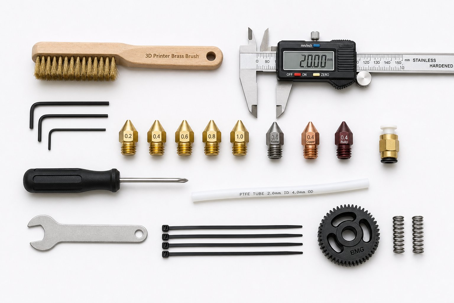
For desktop 3D printers, this means choosing quality nozzles made from appropriate materials for your filament types, replacing drive gears before tooth wear becomes visible under normal lighting, and using PTFE tubing rated for the temperatures your hotend demands. These are relatively inexpensive components, but cutting corners on them guarantees a return trip through the diagnostic checklist sooner than necessary.
The same principle scales directly to industrial plastic extrusion. Production environments running pipe, profile, film, sheet, WPC, or granulation lines face identical categories of failure — just at dramatically different scales and costs. A worn screw barrel on an industrial extruder causes the same type of throughput loss and material inconsistency as a worn hobbed gear on a desktop machine. Industry data shows that manufacturers suffer around 30 percent downtime during scheduled production, and in high-throughput sectors, unplanned stoppages cost orders of magnitude more than the replacement components that would have prevented them.
Industrial screw elements wear at rates determined by the same factors covered throughout this guide: material abrasiveness, operating temperature, alignment, and contamination. Common industrial extruder screw barrel failures — feeding issues, overheating, material mixing inconsistency, barrel contamination, and unusual noises — map directly onto the symptom-to-cause framework used for desktop printers. Feeding capacity drops when screw elements wear. Overheating results from thermal control failures. Contamination degrades both product quality and equipment longevity. The diagnostic thinking is identical; only the component dimensions and replacement costs change.
For extrusion manufacturers, recycling plants, and processing teams that need replacement screw barrels, custom extrusion configurations, or practical component guidance for production-scale equipment, NANHAIYA's plastic extruder machine and screw barrel support page serves as a dedicated resource. Their coverage spans pipe, profile, film, sheet, WPC, and granulation equipment — the full range of extrusion applications where precision-matched components make the difference between consistent output and recurring downtime. Having a reliable industrial extruder screw barrel replacement guide and a responsive component supplier shortens the gap between diagnosis and resolution at every production scale.
Whether you are clearing a clogged nozzle on a desktop printer or replacing a worn screw barrel on a production extruder, systematic diagnosis always outperforms guesswork.
That single sentence captures the entire philosophy behind this guide. The five-step framework — observe, isolate, hypothesize, fix, verify — is not a 3D printing trick. It is an engineering discipline that applies to any system where material flows through a heated channel under mechanical force. Master it on your desktop machine, and you have already learned the diagnostic logic used by production technicians maintaining extruders that run around the clock. Skip it, and you will keep replacing parts that were never broken in the first place.
Stop guessing. Start observing. The fix is almost always simpler than you think — as long as you look in the right place first.
Frequently Asked Questions About Extruder Troubleshooting
1. Why is my 3D printer extruder clicking but not feeding filament?
A clicking extruder typically means the stepper motor is skipping steps because it cannot push filament forward. The three most common reasons are a partial or full nozzle clog creating back-pressure the motor cannot overcome, a drive gear that is clogged with filament dust or has worn teeth that slip instead of gripping, and incorrect idler tension that is either too loose (filament slips) or too tight (filament deforms and jams). To isolate the cause quickly, heat the hotend, release the idler arm, and try pushing filament through by hand. If filament flows freely from the nozzle, the problem is extruder-side — clean the gear teeth, check tension, and verify the motor wiring. If filament will not pass through, you are dealing with a hotend blockage that needs a cold pull or nozzle replacement.
2. How do I tell if the problem is in my extruder or my hotend?
The fastest way to separate extruder-side failures from hotend-side failures is the manual push test. Heat your nozzle to the normal printing temperature, disengage the drive gear by releasing the idler arm, and push the filament into the hotend by hand with steady pressure. If molten filament exits the nozzle smoothly, your hotend is clear and the fault lies upstream — in the motor, drive gear, tension mechanism, or filament path. If filament resists or nothing comes out, a clog or thermal issue inside the hotend is the culprit. This one-minute test eliminates roughly half of all possible causes before you remove a single bolt, saving significant diagnostic time.
3. How often should I perform maintenance on my 3D printer extruder?
A structured maintenance schedule prevents most extrusion failures before they happen. Before every print, visually check the nozzle tip and verify that filament feeds freely during the priming line. Weekly, brush filament dust out of the drive gear teeth and confirm the heatsink fan is spinning at full speed without unusual noise. Monthly, perform a preventive cold pull, inspect your Bowden tube for discoloration or deformation at the cut ends, and verify idler tension by examining gear marks on a pulled-back section of filament. Every three months, consider replacing brass nozzles if you print abrasive materials, re-verify your E-steps calibration, check for firmware updates, and lubricate linear rails. For industrial-scale extrusion equipment, component suppliers like NANHAIYA offer replacement screw barrels and custom configurations at nhyscrew.com to keep production lines running on schedule.
4. What causes mid-print extrusion failure on a 3D printer?
Mid-print extrusion stops are particularly frustrating because they occur after the printer has been running successfully for a period. The most common cause is heat creep — thermal energy migrating upward from the heater block into the cold zone, softening filament prematurely so it swells and jams inside the heatbreak. This typically happens after 30 minutes to several hours of printing and is more prevalent with PLA, in enclosed printers, or when the heatsink fan is underperforming. Other causes include a filament spool tangle that eventually locks the feed, a stepper motor overheating and entering thermal shutdown during long jobs, or a Bowden tube coupler that gradually loosens under sustained extrusion pressure, creating a gap where molten plastic collects and hardens into a plug.
5. Can wet filament cause extrusion problems even if my printer hardware is fine?
Absolutely. Moisture-absorbed filament is one of the most overlooked causes of extrusion failure and can completely undermine a perfectly calibrated machine. Hygroscopic materials like nylon, PETG, PVA, and TPU absorb atmospheric water in a matter of hours when left unsealed. When this wet filament reaches the melt zone, trapped moisture flash-boils into steam, producing audible popping or hissing sounds, bubbled or pitted print surfaces, erratic bead width, weak layer adhesion, and excessive stringing. These symptoms often get misdiagnosed as clogs or temperature errors. The fix is drying the filament in a dedicated dryer or conventional oven at material-specific temperatures — for example, PLA at 45 degrees Celsius for six hours, or PETG at 55 degrees Celsius for six hours. Proper storage in vacuum-sealed bags with desiccant prevents reabsorption.
Written by
Nanhaiya Technical Team
Zhoushan Nanhaiya Plastic Machinery Co., Ltd.
The Nanhaiya technical team supports screw and barrel manufacturing projects through application review, technical communication, custom manufacturing coordination, and production and quality control.
Discuss Your Application
Related Articles
More insights on screw barrel technology and plastics processing.

What Nobody Tells You About Screw Barrel For Plastic Machine Design
Oct 10, 2026
Learn how screw barrel for plastic machine design affects melt quality, throughput, and wear life. Covers geometry, resin matching, troubleshooting, and sourcing.
Read Article
Single Screw Extruder for Sheet: Stop Guessing, Start Specifying
Oct 9, 2026
Learn how to specify a single screw extruder for sheet production. Covers screw geometry, resin-specific processing, troubleshooting, and maintenance best practices.
Read Article
PE Pipe Extruder Machine: What Datasheets Won't Tell You
Oct 9, 2026
Learn how a PE pipe extruder machine works, key specs explained, material grade selection, maintenance tips, and buyer guidance beyond the datasheet.
Read ArticleLooking for something else?
Search by material, symptom or product and jump straight to the relevant page.
These are navigation suggestions based on keyword matching — not a quotation, not a delivery commitment, and not a substitute for engineering review. Final specification is confirmed by our engineers against your drawings and processed material.
Need help with screw barrel selection?
Share your machine model, processed material and application. Our team can help with pricing and technical support.