

What Extruder Screw Wear Repair Means and Why It Matters
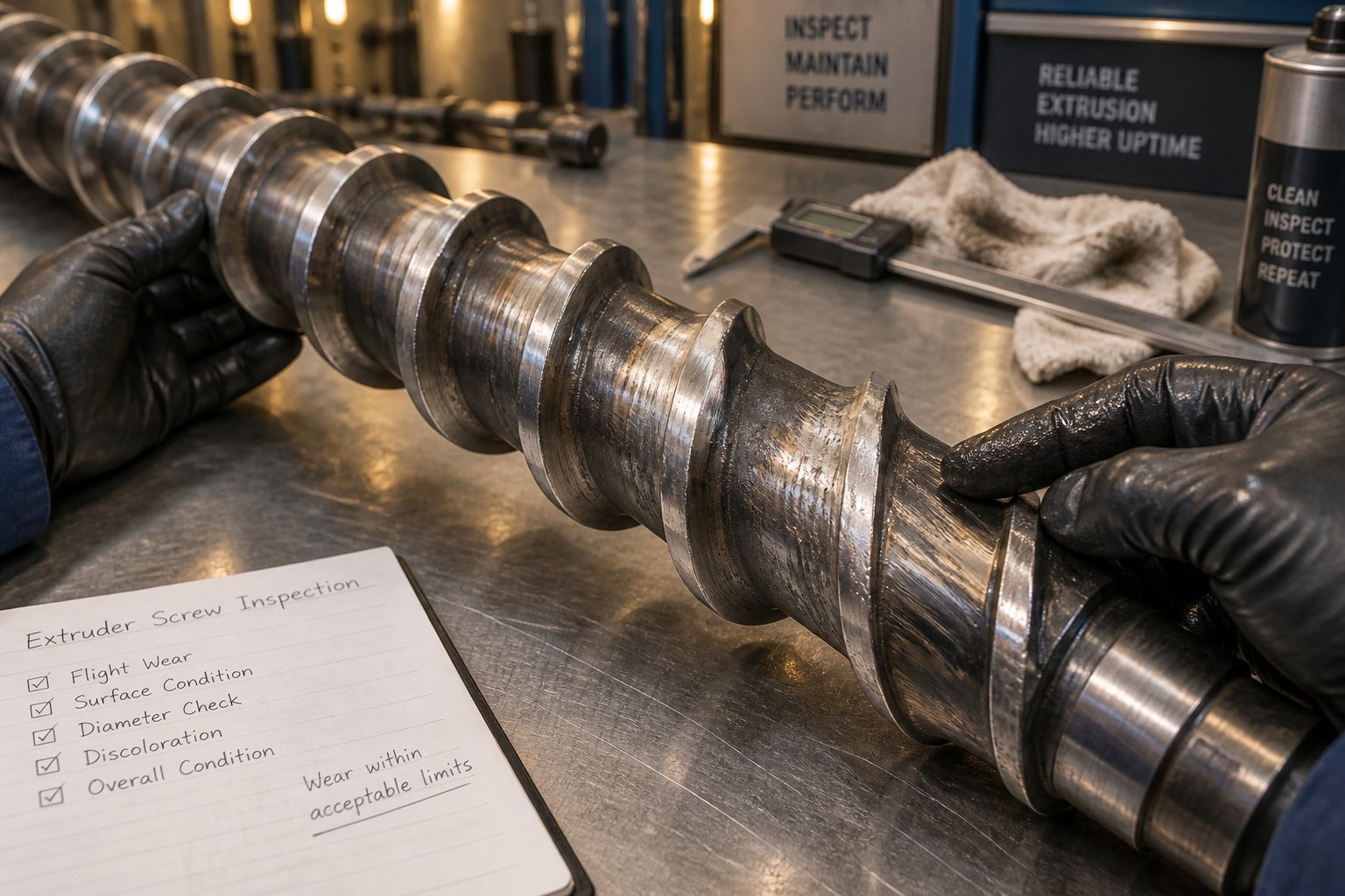
Imagine pulling a screw from your extruder and finding the flight lands visibly worn, the once-sharp edges rounded and uneven. Output has been slipping for weeks, melt temperatures keep creeping up, and your operators have been quietly bumping screw speed to compensate. You're staring at a familiar crossroads: buy a brand-new screw or find a way to restore the one in your hands.
Extruder screw wear repair is the process of restoring worn screw flight geometry, surface hardness, and dimensional tolerances to extend component service life - returning a degraded screw to original or near-original performance specifications without the cost and lead time of full replacement.
That definition matters because it reframes the conversation. Repair is not a stopgap. Done correctly, it delivers a screw that performs on par with new, often at a fraction of the investment.
What Extruder Screw Wear Repair Actually Involves
Replacing extruder screws entirely is the default reaction for many processors, but it is rarely the only option. Repair encompasses a range of precision interventions: flight rebuilding to restore flight height and channel depth, surface re-hardening through techniques like nitriding or hard-facing, overlay welding with wear-resistant alloys, and final machining to bring every dimension back within design tolerances. Each step targets a specific aspect of degradation, and the combination depends entirely on how the screw wore in the first place.
The distinction between repair and replacement hinges on severity. A plastic extruder screw with moderate flight-land erosion and intact root geometry is an excellent repair candidate. One with severe core damage or cracking may genuinely need replacement. The key is knowing where that line falls - and having a clear framework to make the call.
Why a Wear-Type-First Approach Matters
Here's where most repair guidance falls short. Generic advice like "rebuild flights and re-harden" ignores a critical reality: different wear mechanisms demand fundamentally different repair responses. An extrusion screw eroded by glass-fiber abrasion needs a very different overlay alloy and technique than one pitted by corrosive off-gassing from PVC. Applying the wrong fix wastes money and shortens the repair's service life.
This article takes a wear-type-first approach, mapping every repair decision back to the specific wear mechanism at work. You'll follow a complete lifecycle path - from early detection and pattern diagnosis through repair execution, post-repair monitoring, and long-term prevention. Existing industry resources tend to cover causes or repair methods in isolation, but rarely connect all these stages into a single decision-making framework. As Plastics Technology notes, wear on extruder screws and barrels begins the moment the screw starts rotating, and incremental process adjustments often mask the problem until it dramatically impacts quality or productivity. The goal here is to help you act before that tipping point - and choose the right repair path when you do.
Three Wear Mechanisms That Destroy Extruder Screws
Every screw that comes out of a barrel looking beaten up tells a story - but it is not always the same story. The wear pattern etched into the metal reveals which destructive force was at work, and that single piece of information shapes every repair decision that follows. Industry sources and metallurgical research consistently classify extruder screw wear mechanisms into three primary categories: abrasive, corrosive, and adhesive. Each one attacks your extruder screws and barrels through a fundamentally different process, leaves distinct visual evidence, and responds to a specific set of repair strategies.
Misidentifying the mechanism is one of the most expensive mistakes a processor can make. Applying a corrosion-resistant overlay to a screw that failed from abrasive wear is like putting sunscreen on a wound - it addresses the wrong problem entirely. Let's break down each mechanism so you can read the damage accurately and match it to the repair approach that will actually hold up.
Abrasive Wear From Fillers and Reinforcements
If your operation processes filled compounds, abrasive wear is almost certainly your primary adversary. Glass fibers, calcium carbonate, titanium dioxide, talc, and mineral fillers act like microscopic sandpaper as they travel through the screw channels. Every rotation drags these hard particles across the flight lands, channel walls, and barrel bore, physically removing metal through mechanical erosion.
The resulting wear pattern is characteristically uniform. You'll notice a gradual reduction in flight height across the affected zones, with the sharp machined edges of screw and kneading elements appearing rounded, smooth, and occasionally polished. The screw-to-barrel clearance increases progressively, and radial wear tends to be relatively even around the circumference of the flight tips. It is a slow, grinding loss rather than a sudden catastrophic event - which is exactly why it sneaks up on operators who aren't tracking dimensional changes over time.
Several factors accelerate the rate of abrasive damage:
- Filler hardness and particle geometry: Glass fibers are far more aggressive than rounded calcium carbonate particles. Long glass fibers can entangle at the feed port and shear during rotation, forming sharp particles that intensify abrasion as they move downstream.
- Filler loading percentage: A compound with 40% glass fill erodes metal exponentially faster than one at 10%.
- Screw speed and throughput: Higher speeds increase the velocity of abrasive contact, and greater throughput means more abrasive material passes over the same surfaces per hour.
- Base metal hardness: Softer screw substrates lose material faster under identical processing conditions.
The repair response for abrasive wear extruder screw damage centers on rebuilding lost flight geometry and applying hard-facing overlays with high abrasion resistance - typically tungsten carbide composites or cobalt-based alloys that can withstand the relentless mechanical grinding. Re-nitriding alone is rarely sufficient when significant dimensional loss has already occurred.
Corrosive Wear From Chemical Attack
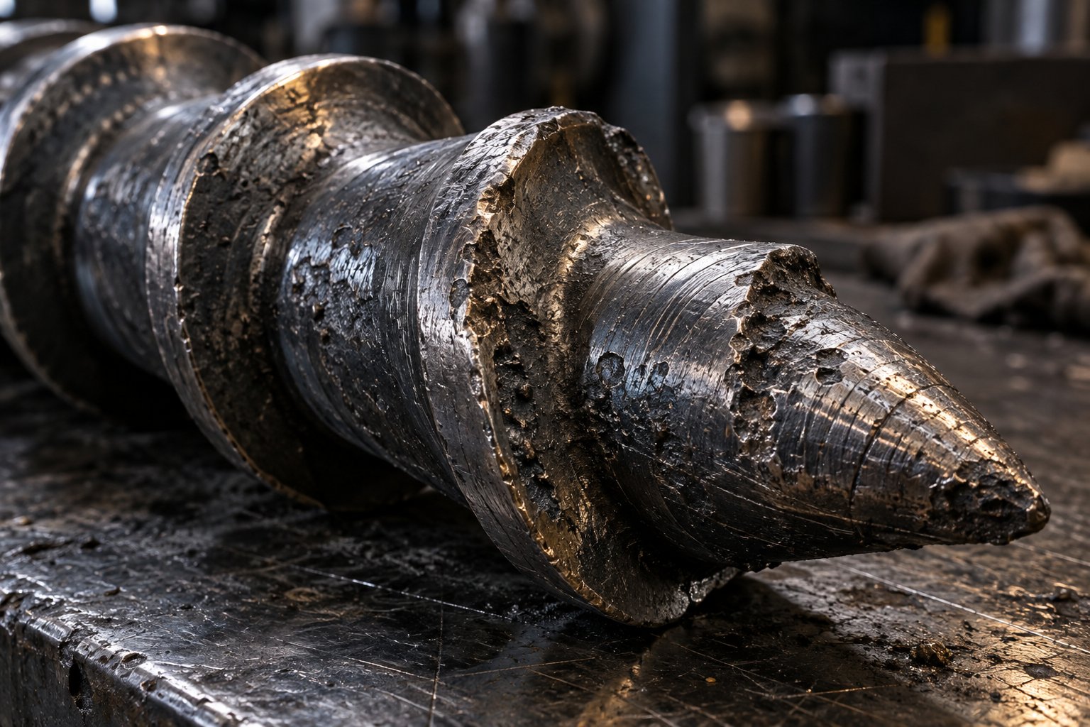
Corrosive wear operates through an entirely different pathway. Instead of physically grinding metal away, chemical reactions between process byproducts and the screw surface dissolve or degrade the metal at a molecular level. The result looks nothing like abrasion - you'll find pitting, cratering, and a rough, etched surface texture rather than the smooth, polished appearance of abrasive erosion.
PVC processing is the most widely recognized source of corrosive wear in extrusion. As PVC degrades thermally, it releases hydrochloric acid gas that attacks unprotected steel surfaces aggressively. But PVC is not the only culprit. Flame retardant additives, certain engineering polymers processed at elevated temperatures, and even moisture trapped in the barrel can trigger oxidation and chemical degradation. Moisture, air, and oxygen inside the barrel accelerate wear through oxidation and corrosion, particularly under high-temperature and high-pressure conditions.
Corrosive wear on an extrusion screw often concentrates in zones where temperature is highest and gas venting is poorest. The damage may appear localized to specific barrel sections rather than distributed uniformly along the screw length - an important diagnostic clue that separates it from abrasion. In twin-screw extruders, corrosion can even develop on chilled barrel sections if condensation forms on internal surfaces, creating a subtle but persistent chemical attack that many operators overlook.
Repairing corrosion-damaged screws demands chemically resistant overlay materials. Nickel-based alloys and certain cobalt-based alloy families provide the inert surface chemistry needed to resist ongoing acid attack. Applying a standard tool steel hard-face over corrosion pitting would simply give the acid a fresh surface to consume.
Adhesive Wear and Metal-to-Metal Contact
Adhesive wear is the most dramatic and potentially destructive of the three mechanisms. It occurs when metal surfaces come into direct contact without adequate lubrication - in this case, the molten polymer film that normally separates screw flights from barrel walls. When that film breaks down, the metals rub directly against each other, and microscopic welding occurs at contact points. As the surfaces pull apart, metal transfers from one component to the other, creating galling, scoring, and in severe cases, seizure.
What causes that protective melt film to fail? Several scenarios are common:
- Cold starts: Running the screw before sufficient polymer melt has formed leaves metal-on-metal contact during startup.
- Improper screw-to-barrel clearance: A screw installed in an undersized or misaligned barrel creates localized high-pressure contact zones.
- Screw deflection under load: In twin-screw extruders, the screws are rigidly fixed at the gearbox end but unsupported at the discharge end. When screws rotate at high speeds between production runs - without molten resin providing support - the shafts can deflect and contact the barrel wall or each other.
- Tramp metal contamination: A bolt or metal fragment entering the feed throat can jam between screw and barrel, triggering immediate galling damage.
Visually, adhesive wear looks very different from the other two types. You'll see score marks, material smearing, localized buildup of transferred metal, and flattened flight tips where the screw was forced against the barrel. The damage is often concentrated on one side of the screw rather than distributed uniformly, reflecting the directional nature of the deflection or misalignment.
Repair for adhesive damage typically involves machining away the galled and work-hardened surface material, rebuilding with weld overlay, and - critically - correcting the root cause before reinstallation. A beautifully repaired screw placed back into the same misaligned setup will gall again within weeks.
Mapping Extruder Screw Wear Mechanisms to Repair Responses
The table below connects each wear type to its root cause, recognizable patterns, and the repair category best suited to address it. Use it as a quick diagnostic reference when evaluating a pulled screw.
| Wear Type | Root Cause | Typical Wear Pattern | Visual Indicators | Recommended Repair Category |
|---|---|---|---|---|
| Abrasive | Glass fibers, mineral fillers, calcium carbonate, titanium dioxide eroding metal through mechanical friction | Uniform flight height reduction; progressive radial clearance increase; even wear across affected zones | Rounded, smooth, polished flight edges; reduced flight OD measurable with micrometer | Hard-facing overlay (tungsten carbide composites, cobalt-based alloys) + flight rebuilding + precision grinding |
| Corrosive | Acidic off-gassing from PVC, flame retardants, moisture, and reactive additives chemically degrading the metal surface | Localized to high-temperature zones and areas with poor venting; non-uniform distribution along screw length | Pitting, cratering, rough or etched surface texture; dimpled appearance distinct from mechanical polishing | Chemically resistant overlay (nickel-based or cobalt-based alloys) + surface rebuilding + improved venting and temperature control |
| Adhesive | Metal-to-metal contact from insufficient melt lubrication, screw deflection, cold starts, misalignment, or tramp metal | One-sided or localized damage; concentrated at discharge end or deflection points; may affect both screw and barrel simultaneously | Score marks, material smearing, transferred metal buildup, flattened flight tips on one side | Machine away galled material + weld overlay rebuild + root cause correction (alignment, startup procedure, support) |
In practice, many screws exhibit a combination of these mechanisms. A glass-filled PVC compound, for instance, delivers both abrasive and corrosive attack simultaneously. That's why accurate pattern recognition matters so much - the overlay alloy and technique must address every active wear mechanism, not just the most visible one.
Recognizing the wear type is the first half of the equation. The second half involves measuring exactly how much material has been lost and determining whether the damage crosses the threshold from repairable to replaceable - a quantitative judgment that changes the entire economic calculation.
Diagnosing Wear Patterns and Connecting Symptoms to Causes
Knowing the three wear mechanisms is essential - but a worn screw doesn't walk up to your desk and announce whether it was abrasion, corrosion, or adhesive contact that did the damage. In most cases, the first clues show up not on the screw itself but in your process data: subtle shifts in output, temperature, pressure, and product quality that gradually worsen over weeks or months. The challenge is recognizing these extruder screw wear symptoms early enough to plan a controlled repair rather than scrambling through an emergency shutdown.
Connecting each symptom to a specific wear pattern - and then to the appropriate repair response - is where most diagnostic guidance falls apart. A general warning to "check your screw when output drops" is not actionable. You need to know what kind of output drop, combined with which other signals, points to which wear mechanism. That's the framework this section builds.
Process Symptoms That Signal Screw Wear
Your extruder talks to you through its process variables. The trick is learning to listen before the conversation turns into a shouting match. Here are the key indicators that progressive screw wear is underway, each linked to the underlying mechanical reality driving it:
Declining output rate at constant screw speed. This is often the earliest and most reliable signal. As flight lands wear down and screw-to-barrel clearance increases, the screw loses its ability to convey material forward efficiently. Polymer leaks back over the worn flight tips instead of being pushed toward the die. You'll notice operators gradually increasing RPM to maintain target throughput - a compensation that masks the real problem while accelerating wear further. This extruder output rate decline follows a predictable curve: slow at first, then steepening as clearance opens beyond a critical threshold.
Rising melt temperature without setpoint changes. Wider clearance forces more material into the high-shear gap between flight tip and barrel wall. That extra shear work converts mechanical energy into heat, pushing discharge melt temperatures above their historical baseline. MachineCDN's predictive maintenance data suggests that melt temperature deviations of +8 to +15 degrees Fahrenheit above baseline indicate marginal screw condition, while deviations exceeding +15 degrees Fahrenheit signal a screw approaching the replacement threshold.
Melt pressure instability and surging. A healthy screw delivers a steady melt stream with pressure variation typically under +/-50 PSI during stable operation. As wear progresses, the solid bed in the compression zone breaks up inconsistently, creating pulsating flow. You'll see this as cyclical pressure swings at the die - and if you're running sheet or pipe, it shows up as thickness variation in the product before anyone traces it back to the screw.
Increased specific energy consumption. When the screw can no longer efficiently convey and melt polymer, the drive motor works harder for each kilogram of output. Tracking kilowatt-hours per pound of throughput over time creates a wear fingerprint. A rise of 10-15% above baseline is a reliable indicator of meaningful wear progression.
Visible product quality degradation. Gels, unmelts, color streaks, and poor dispersion are late-stage symptoms. By the time these appear consistently, the screw has likely crossed from the "plan a repair" zone into the "repair urgently" zone. Unmelted particles indicate the compression section can no longer generate sufficient pressure to complete melting, while color streaks suggest the mixing section geometry has degraded enough to allow unmixed material to pass through.
The real power in screw wear pattern diagnosis comes from trending these variables together rather than watching any single one in isolation. A simultaneous decline in output rate, rise in melt temperature, and increase in motor amperage at constant RPM is a classic three-signal confirmation of progressive clearance wear. Continuous monitoring platforms that correlate screw speed versus output rate data can reveal this trajectory weeks before it reaches the point of catastrophic failure - transforming screw repair from an emergency event into a planned maintenance activity.
Interpreting Physical Wear Patterns on the Screw
Process data tells you something is wrong. The screw itself tells you what went wrong. When you pull the screw during a scheduled shutdown or planned inspection, the physical wear pattern is your most reliable guide to both root cause identification and repair urgency. Here's what to look for:
- Radial wear (uniform clearance increase around the full circumference): This is the hallmark of abrasive wear. Flight tips are worn evenly, edges are rounded and polished, and the wear may span long sections of the screw. Root cause: filled or reinforced compounds eroding metal mechanically. Repair urgency: moderate - this wear is progressive and predictable, so repair can usually be planned around production schedules. Hard-facing overlay with abrasion-resistant alloys is the standard repair path.
- Axial wear (localized to specific screw zones): When wear concentrates in the compression section, a specific mixing element, or the metering zone while other sections remain relatively intact, the problem often traces back to screw design limitations, localized processing conditions, or material-specific issues in that zone. Root cause: design mismatch, excessive shear in a specific zone, or localized thermal degradation. Repair urgency: moderate to high - targeted zone repair is often straightforward, but the root cause (potentially inadequate screw design for the application) must be addressed or the repaired zone will wear again at the same accelerated rate.
- Localized pitting and surface erosion: Clusters of pits, craters, or a rough etched texture concentrated in high-temperature zones or poorly vented sections point directly to corrosive attack. Root cause: chemical degradation from acidic off-gassing, moisture, or reactive additives. Repair urgency: high - corrosion is self-accelerating because pits create stress concentrations and trap corrosive byproducts, deepening damage with each production hour. Chemically resistant nickel-based or cobalt-based overlays are essential, and venting improvements should accompany the repair.
- Flight-tip galling and one-sided scoring: Flattened or smeared flight tips concentrated on one side of the screw, often with visible transferred metal, are unmistakable signs of adhesive wear from metal-to-metal contact. Root cause: screw deflection, misalignment, cold-start damage, or tramp metal contamination. Repair urgency: high to critical - adhesive damage often affects both screw and barrel simultaneously, and the root cause (alignment, support, startup procedure) must be corrected before reinstallation or the repaired screw will gall again rapidly.
Many screws pulled from service show a combination of these patterns. A glass-filled flame-retardant compound, for example, might produce uniform radial wear from abrasion along the full screw length plus localized pitting in the venting zone from corrosive off-gassing. Accurate pattern reading ensures the repair addresses both mechanisms - an abrasion-only overlay in the venting zone would corrode within months.
How Barrel Condition Influences Screw Diagnosis
Here's a diagnostic blind spot that leads to costly repeat failures: evaluating the screw without measuring the extruder barrel. Screw and barrel form an integrated system. The clearance that determines pumping efficiency, shear rate, and melt quality is a function of both components - the screw's flight outside diameter and the barrel's bore inside diameter. Measuring only one side of the equation gives you half the picture.
Consider a common scenario. You pull a screw showing moderate radial wear and send it for flight rebuilding and hard-facing overlay. The repaired screw comes back with flight ODs restored to original spec. You install it, start up, and output seems better - for a few weeks. Then the same symptoms return far sooner than expected. What happened? The barrel bore had also worn beyond its original diameter. Your "restored" clearance was actually still excessive because the barrel's contribution to the gap was never addressed.
This is why bore gauging the barrel should be a non-negotiable part of every screw wear diagnosis. Xtrutech recommends checking inside the extruder barrel regularly so that wear can be assessed in the early stages and corrective action taken before additional damage occurs. For twin-screw extruders with clamshell barrels, this inspection is straightforward. For single-screw machines with fixed barrels, bore gauging at multiple points along the barrel length reveals whether wear is uniform or concentrated in specific zones.
The barrel's condition directly changes the repair calculus. If the barrel bore is still within tolerance, screw repair alone restores proper clearance. If the barrel has worn moderately, you may need to undersize the repaired screw's flight OD to split the difference - though this compromises ideal geometry. And if barrel wear is severe, repairing the screw without also re-sleeving or replacing the barrel is simply throwing money away. The clearance will remain excessive regardless of how perfectly the screw flights are rebuilt.
Diagnosing wear accurately - both the type and the severity, across both components - is what separates a repair that lasts from one that fails in months. But diagnosis alone doesn't tell you whether to repair or replace. That decision requires specific dimensional thresholds: exactly how much clearance is too much for repair, and when does the math favor a new screw instead?
Wear Measurement Thresholds and the Repair vs Replace Decision
Symptoms point you in the right direction. Physical wear patterns narrow the possibilities further. But the final call - repair the screw and barrel or replace them - depends on numbers, not instinct. Specifically, it depends on the measured clearance between screw flight outside diameter and barrel bore inside diameter, compared against the original design specification. Without those numbers, every repair decision is a guess.
The frustrating reality is that most maintenance teams skip this step entirely. They eyeball the screw, see visible wear, and either send it for repair or order a replacement based on gut feel. That approach works sometimes. It also leads to wasted repair investments on screws that were too far gone, or unnecessary replacements of screws that had thousands of production hours left in them.
Measuring Screw and Barrel Clearance
Accurate barrel wear measurement requires two separate sets of data points collected with the right instruments. Here's the standard methodology:
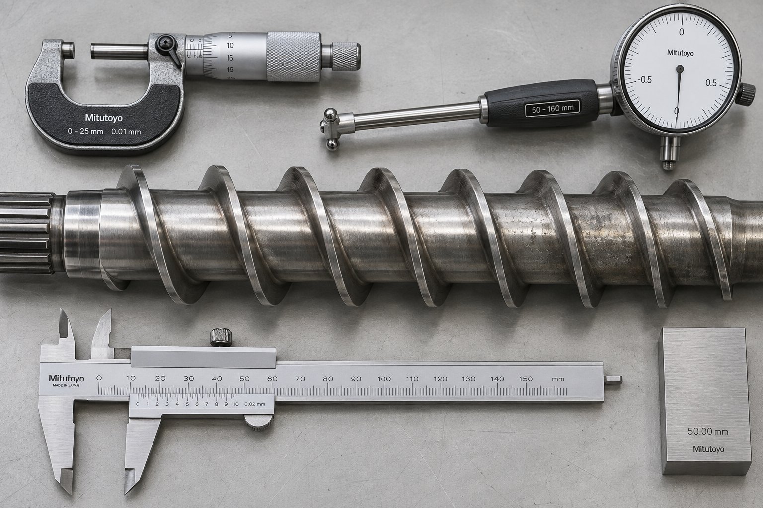
Barrel bore measurement. A bore gauge (also called an inside micrometer or telescoping gauge for smaller diameters) measures the internal diameter of the barrel at multiple points along its length. You'll want readings at regular intervals - every four to six inches in the feed, compression, and metering zones - and at multiple clock positions (typically 0, 90, 180, and 270 degrees) at each axial location. This circumferential mapping reveals not just diameter increase but also ovality, which indicates directional wear from screw deflection or gravity sag. Dedicated laser-based barrel measurement devices use 360-degree rotating sensors to capture this data with high precision and repeatability, turning subjective inspection into quantified wear maps.
Screw flight OD measurement. An outside micrometer measures the flight outside diameter at matching axial positions along the screw. Take readings across the full flight tip - not just at one point - because localized wear or one-sided galling can create significant variation around a single flight. Record measurements in the feed section, compression section, metering section, and any mixing or barrier zones independently, since wear rates differ dramatically across these functional zones.
Calculating actual clearance. The math is straightforward: subtract the screw flight OD from the barrel bore ID at each measurement station, then divide by two. That gives you the radial clearance - the gap between one flight tip and the barrel wall. Compare this value against the original design clearance, which for most single-screw extruders falls in the range of 0.001 to 0.002 inches per side per inch of barrel diameter (though specific OEM specs vary). The percentage increase over original design clearance is your key decision metric.
As a general principle, when screw to barrel clearance exceeds roughly two to three times the original design specification, repair should be actively planned. When clearance opens beyond approximately four to five times the original spec, the screw and barrel system has typically degraded past the point where screw repair alone can restore acceptable performance. These thresholds shift depending on the polymer being processed - a high-viscosity HDPE pipe application is more forgiving of clearance increase than a precision medical tubing line running tight-tolerance fluoropolymer.
Repair Versus Replacement Decision Framework
The extruder screw repair vs replacement decision is never just about the screw. It's a system-level judgment that must account for both components simultaneously. Repairing a screw to perfect dimensions and reinstalling it in a barrel with excessive bore wear wastes the entire repair investment - the clearance remains too large regardless of how beautifully the flights were rebuilt.
Walk through these questions in sequence to arrive at the right path:
- What wear type is present? Abrasive, corrosive, adhesive, or a combination? This determines which overlay alloy and technique apply.
- How severe is the dimensional loss? Use your clearance measurements against design spec to classify severity.
- What materials are being processed? Abrasive glass-filled compounds will re-wear a marginal repair quickly. Unfilled commodity resins are more forgiving. Material type strongly affects how quickly screws and barrels need attention, with glass fiber compounds and mineral-filled plastics driving the fastest wear rates.
- What is the barrel condition? A screw repair only makes economic sense if the barrel bore is still within a serviceable range - or if you're prepared to address both components together.
The table below maps these variables into actionable recommendations:
| Wear Severity Level | Typical Clearance Condition | Screw Status | Barrel Status | Recommended Action |
|---|---|---|---|---|
| Mild | Clearance 1.5x to 2x original design spec | Flight edges show early rounding; dimensions still near tolerance | Bore within or near original spec | Monitor closely; schedule repair at next planned shutdown; re-nitriding or light hard-facing may suffice |
| Moderate | Clearance 2x to 3x original design spec | Measurable flight height loss; visible wear pattern consistent with identified mechanism | Bore slightly enlarged but within serviceable limits | Repair screw with appropriate overlay and flight rebuild; verify barrel bore is still acceptable before reinstallation |
| Severe | Clearance 3x to 5x original design spec | Significant flight loss; core geometry may show early compromise | Bore moderately worn; approaching or at upper service limit | Repair both screw and barrel (re-sleeve or re-line barrel); evaluate whether repair cost approaches replacement economics |
| Critical | Clearance exceeding 5x original design spec | Severe dimensional loss; possible core cracking, deep galling, or structural compromise | Bore significantly oversized; scoring, ovality, or liner damage present | Replace screw and barrel; repair is unlikely to restore adequate service life to justify the investment |
Notice how every row in this framework evaluates both components. That dual assessment is the single most important principle in the entire repair-versus-replace decision. A moderate-severity screw paired with a barrel still in good shape is an excellent repair candidate. That same screw paired with a severely worn barrel is a poor investment unless you address the barrel simultaneously.
One practical tip worth emphasizing: document your measurements and keep historical records. A single measurement snapshot tells you where you are today. A trend across multiple inspections tells you how fast you're getting there - and that wear rate data is what transforms reactive maintenance into predictive planning. You'll know months in advance when the next repair or replacement window is approaching, giving you time to evaluate repair techniques, source overlay materials, and coordinate downtime without emergency pressure.
With the diagnostic framework and decision thresholds established, the next critical question becomes practical: which specific repair technique delivers the best result for your particular wear type, screw geometry, and performance requirements?
Repair Techniques Compared From Weld Overlay to Thermal Spray
You've identified the wear type, measured the clearance, and confirmed the screw is a viable repair candidate. The next decision is arguably the most consequential: which repair technique should be applied? The answer determines how long the repaired screw will last, how well it resists the specific wear mechanism that caused the original damage, and whether the investment delivers real value or just delays replacement by a few months.
The landscape of available techniques spans two broad families - weld overlay methods that fuse material metallurgically to the screw substrate, and thermal spray or surface coating processes that build up protective layers through different deposition mechanisms. Each family includes several distinct techniques, and the performance differences between them are significant. Choosing the wrong method for your wear type is just as costly as choosing the wrong overlay alloy.
Weld Overlay and Hard-Facing Methods
Weld overlay techniques share a common principle: they melt both the overlay alloy and a thin layer of the screw's base metal, creating a metallurgical bond that becomes part of the screw itself. This fusion bond is the strongest attachment method available, making weld overlays the preferred choice for rebuilding flight tips and other high-contact surfaces that endure constant mechanical loading during extrusion.
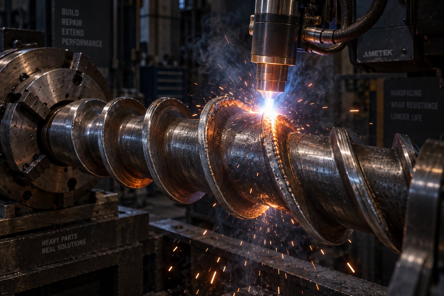
Plasma Transferred Arc (PTA) welding is the workhorse of hard facing extruder screw flight tips. A transferred direct-current plasma arc melts alloy powder directly onto the screw surface, producing thick, precisely placed deposits with low dilution - meaning the overlay retains most of its intended alloy composition rather than mixing excessively with the base steel. PTA welding extruder screw repairs are particularly effective for flight-tip rebuilding because the process allows accurate deposition exactly where material was lost. As TAN STAR notes, PTA creates a durable metallurgically bonded alloy layer on critical screw-flight wear areas, and multiple alloy systems can be selected to balance wear resistance and corrosion protection for different processing environments. The trade-off? PTA's high heat input creates a wider heat-affected zone (HAZ) in the base metal, which can cause microstructural changes in the substrate beneath the overlay.
Laser cladding uses a focused high-energy laser beam to melt powder and substrate simultaneously, but the energy is far more concentrated than PTA. The result is a metallurgically bonded deposit with a minimal heat-affected zone and extremely low dilution. For precision screws with tight dimensional requirements - or screws made from heat-sensitive substrates - laser cladding offers a clear advantage. Research into PTA versus laser cladding for overlay applications consistently shows that laser cladding achieves lower dilution than PTA, making it preferable when exact alloy composition in the finished deposit is critical to performance. The downside is higher equipment cost and lower deposition rates, which translates to longer processing times for large screws with extensive wear.
Conventional MIG/TIG hard-facing remains the most accessible and cost-effective weld overlay method. Standard arc welding processes deposit hard-facing alloy wire or rod directly onto worn surfaces. The metallurgical bond is strong, and the technique works well for less critical zones - root diameter buildup, back-of-flight reinforcement, and general dimensional restoration in areas that don't experience direct flight-tip-to-barrel contact. The limitation is higher heat input and dilution compared to PTA or laser methods, which means the overlay's wear properties may be somewhat reduced by mixing with base metal. For screws processing unfilled commodity resins where extreme hardness isn't essential, conventional hard-facing offers excellent value.
Thermal Spray and Surface Coating Techniques
Thermal spray screw repair techniques take a fundamentally different approach. Instead of melting the substrate, they accelerate alloy particles onto the prepared screw surface at high velocity, building up a dense protective coating without significantly heating the underlying metal. This preserves the base screw's metallurgy but creates a mechanical or diffusion bond rather than a full metallurgical fusion.
Alloy spray welding (thermal spray with fused overlay) bridges the gap between spray coatings and weld overlays. The process first sprays alloy powder onto the screw surface, then fuses the deposit using a secondary heat source - typically an oxyacetylene torch or induction heating. This two-step approach produces a coating that is denser and better bonded than a simple thermal spray, with controlled thicknesses typically in the 1-2mm range. Various alloy powders can be matched to specific wear types, making alloy spray welding a versatile repair method across different extrusion barrel and screw combinations.
HVOF (High Velocity Oxygen Fuel) spray coating accelerates alloy particles toward the screw surface at supersonic velocities, creating an exceptionally dense coating with very low porosity. Unlike PTA welding, HVOF does not melt the base material at all - the coating adheres through a dense mechanical bond. Tungsten carbide (WC-Co) HVOF coatings deliver outstanding abrasion resistance suitable for processing glass fiber reinforced compounds at loadings up to 60%, while nickel-chromium HVOF coatings target corrosion resistance in chemically aggressive environments. The primary limitation is that HVOF coatings are typically thinner than weld overlays, making them better suited for surface protection on screws with minor dimensional loss rather than major flight rebuilding.
Hard-chrome plating is among the oldest surface restoration methods still in use. An electrochemical process deposits a thin, hard chromium layer across the screw surface. It's effective for restoring minor dimensional loss and improving surface hardness on lightly worn screws, but the coating is relatively thin and can chip or spall under heavy mechanical loading. Chrome plating works best as a finishing treatment after other repair methods have restored gross geometry, or as a standalone solution for screws with only surface-level wear running unfilled or mildly filled resins.
Re-nitriding doesn't add material at all. Instead, it restores surface hardness by diffusing nitrogen into the screw's outer layer through a controlled heat treatment process. This works only on nitrided steel screws with minor wear - the technique can't rebuild lost flight height, but it can restore the hardened case on flight surfaces that have been lightly worn through the original nitrided layer. Think of it as refreshing the armor on a screw that's barely been scratched, not rebuilding one that's been ground down. As a comparative study of hardfaced layer properties demonstrates, the relationship between surface hardness and abrasive wear resistance follows a strong linear correlation - which is precisely why restoring that hardened surface case through re-nitriding can meaningfully extend service life when dimensional loss is still within tolerance.
Technique Comparison at a Glance
The table below provides a side-by-side comparison across the key performance variables that matter for extruder screw wear repair decisions. Surface hardness values on the Rockwell C scale vary significantly across techniques, directly influencing how well the repaired surface resists abrasive versus corrosive environments.
| Technique | Best For (Wear Type) | Coating Thickness Range | Relative Hardness Achievable | Durability Expectation | Relative Cost | Limitations |
|---|---|---|---|---|---|---|
| PTA Welding | Abrasive and combined abrasive/corrosive wear; flight-tip rebuilding | 1.5 - 4.0+ mm | 55 - 65 HRC (varies by alloy; carbide-reinforced overlays can reach higher matrix hardness) | High; metallurgical bond resists delamination under continuous mechanical loading | Moderate to high | Higher heat input creates wider HAZ; requires post-weld machining to restore precise geometry |
| Laser Cladding | Precision screws; heat-sensitive substrates; corrosive and abrasive wear requiring tight compositional control | 0.5 - 2.0 mm per pass | 55 - 65 HRC (alloy dependent; low dilution preserves target hardness more consistently) | High; excellent deposit integrity with minimal residual stress | High | Lower deposition rate; higher equipment cost; less suited for thick buildup on heavily worn screws |
| Alloy Spray Welding | Moderate abrasive and corrosive wear; versatile across screw and extrusion barrel applications | 1.0 - 2.0 mm | 45 - 62 HRC (alloy dependent) | Good; fused overlay creates a strong bond superior to unfused thermal spray | Moderate | Requires secondary fusing step; less precise deposit placement than PTA |
| HVOF Spray Coating | Severe abrasive wear (WC-Co coatings); corrosive environments (Ni-Cr coatings) | 0.1 - 0.5 mm | 60 - 72 HRC (WC-Co coatings can exceed 70 HRC equivalent) | High surface hardness and density; excellent abrasion resistance in thin-coat applications | Moderate to high | Thin coating limits use for major dimensional restoration; mechanical bond less robust than metallurgical fusion under severe impact |
| Hard-Chrome Plating | Minor surface wear; dimensional touch-up; general corrosion barrier | 0.02 - 0.25 mm | 65 - 70 HRC (surface only; thin layer) | Moderate; can chip or spall under heavy point loading or thermal cycling | Low to moderate | Very thin deposit; cannot rebuild significant dimensional loss; environmental regulations increasingly restrict chrome plating processes |
| Re-Nitriding | Minor surface hardness loss on nitrided steel screws; preventive rehardening | No material addition (case depth restoration typically 0.1 - 0.3 mm) | 55 - 65 HRC (restores original nitrided case hardness) | Good for extending life on lightly worn screws; limited if original case was fully worn through | Low | Cannot restore lost dimensions; ineffective if wear has penetrated beyond original nitrided case depth; only applicable to nitriding-grade steels |
A few patterns emerge from this comparison. PTA welding and laser cladding dominate when significant flight geometry needs rebuilding - they can deposit enough material to restore dimensional loss measured in millimeters, and the metallurgical bond ensures the overlay stays put under the continuous shear forces inside an extrusion barrel. HVOF coatings excel at surface protection where extreme hardness in a thin layer matters most, particularly for screws running highly abrasive glass-filled compounds. Alloy spray welding occupies a practical middle ground - versatile, reasonably priced, and effective across a broad range of wear scenarios. Re-nitriding and chrome plating serve as finishing touches or standalone treatments for screws caught early in their wear cycle.
No single technique is universally superior. The right choice always maps back to the wear type identified during diagnosis, the severity of dimensional loss measured during inspection, and the processing environment the screw will return to. A screw processing 40% glass-filled nylon with severe flight erosion demands PTA welding with a tungsten carbide composite overlay. A lightly worn screw running unfilled polypropylene might only need re-nitriding. Matching technique to context is everything - and so is matching the overlay alloy itself to the specific polymer and filler combination that caused the damage in the first place.
Selecting the Right Repair Coating and Overlay Material
Picking the right repair technique is only half the battle. A perfectly executed PTA weld or flawlessly fused thermal spray coating will still fail prematurely if the overlay alloy doesn't match the wear mechanism destroying your screw. Imagine rebuilding flight tips with a beautiful cobalt alloy overlay - only to watch it erode within months because the real threat was tungsten-carbide-level abrasion from 40% glass fill, not the moderate combined wear that cobalt alloys handle best. Screw overlay alloy selection is where metallurgical science meets practical extrusion economics, and getting it wrong is one of the most expensive mistakes in the entire repair process.
Matching Overlay Alloys to Wear Mechanisms
Four broad alloy families dominate extruder screw wear repair, each engineered to resist a specific type of attack. Understanding their strengths and trade-offs lets you match metallurgy to your actual operating environment rather than defaulting to whatever the repair shop has in stock.
Cobalt-based alloys (Stellite family). These are the versatile all-rounders of screw overlay metallurgy. Stellite alloys deliver a strong combination of abrasion resistance, corrosion resistance, and high-temperature hardness retention - typically ranging from 38 to 55 HRC depending on the specific grade. They excel in applications where both mechanical erosion and chemical attack occur simultaneously, such as processing flame-retardant-filled engineering polymers at elevated temperatures. Their ability to maintain hardness well above 500 degrees Celsius makes them particularly suited for high-temperature extrusion environments where softer alloys would lose their protective edge.
Nickel-based alloys (Colmonoy family). When corrosion is the dominant threat, nickel-based overlays are the go-to choice. These alloys form a chemically inert surface barrier that resists acid attack from PVC off-gassing, halogenated flame retardants, and fluoropolymer degradation products. Hardness typically falls in the 40 to 62 HRC range depending on the grade and application method. Nickel-based alloys sacrifice some pure abrasion resistance compared to carbide composites, but their corrosion immunity makes them indispensable for extrusion barrels and screws exposed to chemically aggressive processing environments. PVC screw and barrel systems frequently require this level of chemical protection because thermal degradation generates hydrochloric acid that rapidly attacks unprotected steel surfaces.
Tungsten carbide composites. For extreme abrasive wear, nothing outperforms a tungsten carbide screw coating. These composites embed ultra-hard tungsten carbide particles within a metallic matrix (typically nickel or cobalt), creating a surface that resists mechanical erosion from glass fibers, mineral fillers, and other hard additives far longer than any single-phase alloy. Effective hardness can exceed 70 HRC equivalent at the carbide particle level, though the matrix between particles is softer. The trade-off is reduced impact toughness and higher cost - but for screws processing compounds with 30% or more glass fiber loading, the extended service life typically justifies the investment many times over. Research into glass fiber reinforced thermoplastics consistently demonstrates how aggressively these fibers erode processing equipment, with fiber breakage during compounding creating sharp fragments that intensify the abrasive attack on screw surfaces.
Tool steel overlays. When cost efficiency is the priority and the wear environment is relatively mild, tool steel hard-facing provides a practical rebuild option. These overlays restore dimensions and deliver moderate hardness - typically 45 to 55 HRC - at a lower material cost than specialty alloys. They're well-suited for general-purpose rebuilding on screws processing unfilled commodity resins or lightly filled compounds where extreme wear resistance isn't the primary concern. Think of tool steel overlays as the economical workhorse: effective enough for standard duty, but outclassed when aggressive fillers or corrosive chemistries enter the picture.
How Processed Polymers and Fillers Drive Material Choice
The alloy family discussion above provides the metallurgical foundation. The polymer and filler combination running through your extruder is what pins down the specific recommendation. This is where many repair decisions go sideways - a shop selects an alloy based on general hardness requirements without considering the actual chemical and mechanical environment the screw will face. Your material formulation should drive every aspect of wear resistant screw surface treatment selection.
Here's how common processing scenarios map to recommended overlay alloy families:
- Glass-fiber-reinforced compounds (PA, PP, PBT with 15-60% glass fill): Tungsten carbide composite overlays. Glass fibers are among the most abrasive fillers in plastics processing, and higher loading percentages accelerate wear exponentially. Screws processing these materials need the maximum abrasion resistance available.
- Calcium carbonate and mineral-filled polyolefins: Cobalt-based alloys (Stellite) or tungsten carbide composites, depending on filler loading. CaCO3 at 20% or below may be manageable with cobalt alloys; loadings above 30% typically warrant the jump to carbide composites.
- PVC compounds (rigid and flexible): Nickel-based alloys (Colmonoy family). The primary threat is chemical - hydrochloric acid from thermal degradation - rather than mechanical. Corrosion resistance takes priority over maximum hardness.
- Fluoropolymers (PTFE, FEP, PFA): Nickel-based or high-nickel cobalt alloys. Fluoropolymer degradation releases hydrofluoric acid, which is even more aggressive than HCl. The overlay must provide exceptional chemical inertness.
- Flame-retardant-filled engineering polymers: Cobalt-based alloys or dual-protection strategies combining corrosion-resistant underlayers with abrasion-resistant top coats. Flame retardant additives create a double threat - halogenated compounds off-gas corrosive byproducts while the filler particles themselves cause mechanical erosion. This combined attack demands an overlay strategy that addresses both mechanisms simultaneously.
- Unfilled commodity resins (PE, PP, PS): Re-nitriding or standard tool steel hard-facing. These materials create minimal wear demand, so the most cost-effective surface restoration is usually sufficient. Investing in premium carbide overlays for an unfilled PE screw is spending money where it delivers no measurable return.
- Recycled plastics with unknown contaminants: Cobalt-based alloys as a baseline, with tungsten carbide composites if the feedstock contains significant mineral or metallic contamination. Recycled materials are inherently unpredictable - metal particles, mineral contamination, and other hard impurities can appear intermittently, so the overlay must tolerate both abrasion and occasional impact events.
One technique worth highlighting in this material-selection context is alloy spray welding. Its versatility lies in the wide range of alloy powders that can be applied through the spray-and-fuse process, making it adaptable to many of the polymer-filler scenarios listed above. For operators evaluating their options across different wear types and processing environments, service providers like NANHAIYA offer alloy spray welding specifically designed for wear resistant screw surface treatment, supporting both extrusion and injection molding operations with alloy selection tailored to each application's unique demands.
Alloy selection and technique selection are deeply intertwined - not every technique can deposit every alloy effectively, and certain alloy-technique pairings deliver better results than others. Tungsten carbide composites, for instance, perform best when deposited via PTA welding or HVOF spray because these processes preserve the carbide particle integrity. Nickel-based Colmonoy alloys work well across PTA, alloy spray welding, and laser cladding. Choosing the alloy first, then confirming the technique can deliver it properly, is the correct sequence.
With the right alloy matched to your wear mechanism and the right technique confirmed to deliver that alloy effectively, the repair process itself becomes the focus - a precise sequence of inspection, preparation, deposition, machining, and verification steps that determines whether the finished screw truly performs like new or falls short of expectations.
Extruder Screw Repair Process: Step-by-Step From Inspection to Verification
Alloy and technique decisions set the stage, but the quality of the finished repair lives or dies in the execution. A poorly sequenced workflow - skipping pre-machining, rushing the cooling phase, or grinding without verifying hardness - can undermine even the most expensive overlay alloy. The extruder screw repair process follows a disciplined sequence with specific objectives at each stage, and understanding why each step matters helps you evaluate whether your repair partner is cutting corners or doing the job right.
Initial Inspection and Documentation
Every reliable repair starts with a thorough forensic examination of the screw - not a quick glance and a quote. You want data, not opinions. Here's what a comprehensive inspection covers:
- Dimensional measurement across all functional zones. Feed section, compression section, metering section, and any mixing or barrier flight zones should each be measured independently. Flight outside diameter, root diameter, flight width, channel depth, and pitch are all recorded at multiple axial stations. These measurements quantify exactly how much material has been lost and where, forming the blueprint for every screw flight rebuilding step that follows.
- Photographic documentation. High-resolution images of wear patterns, pitting, galling marks, and surface condition create a visual record that supports root cause analysis. They also serve as a baseline to compare against post-repair results and future inspections.
- Hardness testing of remaining surfaces. Portable Rockwell or Leeb hardness testers measure the residual hardness of the screw's surface at multiple points. If the nitrided case or previous hard-facing has been worn through, the underlying softer substrate may be exposed - a critical finding that changes the overlay strategy.
- Root cause assessment. This is where the inspection moves beyond "what happened" to "why it happened." Was the wear pattern consistent with the processed material? Did the barrel condition contribute? Were there signs of misalignment or cold-start damage? Identifying the root cause before repair prevents sending a beautifully restored screw back into the same failure scenario.
One area that deserves special attention during inspection is screw design geometry. Worn mixing sections, barrier flights, and specialized elements like Maddock mixers or pin mixers require fundamentally different repair approaches than straightforward metering-section flight rebuilding. Twin-screw extruder elements - including kneading blocks with varying stagger angles (30, 45, 60, and 90 degrees) and specialized components like ZME and SME elements - present even more complex geometries that demand precise documentation before any material is deposited. Skipping this step risks altering the screw's functional characteristics during the rebuild.
Surface Preparation and Repair Execution
With the inspection data in hand, the actual repair follows a carefully controlled sequence. Rushing or reordering these steps introduces defects that compromise the finished product.
- Cleaning and degreasing. All residual polymer, carbon deposits, and surface contaminants must be removed completely. Any contamination trapped beneath the new overlay creates weak spots prone to delamination. Chemical cleaning with appropriate purging compounds followed by solvent degreasing ensures a pristine substrate.
- Stripping existing worn coatings. If the screw previously had chrome plating, a nitrided layer, or an earlier overlay that has partially failed, these remnants must be removed down to sound base metal. Depositing new material over a compromised existing coating is a recipe for early failure - the new overlay is only as strong as what's underneath it.
- Pre-machining to establish a uniform substrate. This step is often overlooked, and skipping it is a common source of repair failures. Worn surfaces are irregular - some areas have lost more material than others, and galling damage creates hardened ridges. Pre-machining turns the screw down to a uniform undercut diameter, giving the overlay process a consistent starting surface. Without this step, the deposited material varies in thickness, creating stress concentrations and uneven wear in service.
- Overlay application via the selected technique. Whether PTA welding, laser cladding, alloy spray welding, or another method, the deposition is performed according to parameters calibrated for the specific alloy and substrate combination. Multi-pass applications build up material gradually, and each pass is inspected before the next begins. Bead placement, travel speed, powder feed rate, and shielding gas flow all affect the quality of the deposit.
- Controlled cooling to prevent thermal stress cracking. This is a critical and time-sensitive phase. Rapid cooling introduces residual stresses that can crack the overlay or the heat-affected zone in the base metal. Depending on the alloy system and screw diameter, controlled cool-down may involve furnace cooling, insulating blankets, or slow ambient cooling over many hours. Larger screws used in barrel extruder systems with diameters above 6 inches are especially susceptible to thermal shock during this stage.
- Post-weld heat treatment (if required). Certain alloy systems - particularly those with high chromium or carbon content - require a stress-relief heat treatment after deposition to stabilize the metallurgical structure and prevent delayed cracking. The specific temperature and hold time depend on the overlay and substrate alloy combination. Skipping this step when the alloy system calls for it virtually guarantees premature cracking in service.
Final Machining and Quality Verification
The overlay is on, the screw has cooled, and post-weld heat treatment is complete. The screw at this point looks rough - built up with excess material, uneven bead profiles, and an OD well above the final target dimension. Final machining transforms that raw rebuild into a precision component.
Precision grinding restores the flight geometry to original tolerances - or, if the screw is being built oversized to match a worn barrel, to the specific target dimensions documented during the inspection phase. CNC machining centers and cylindrical grinders achieve the tight concentricity and dimensional consistency required. Specialized repair facilities use CNC machining centers to ensure that each flight's profile matches the barrel precisely, optimizing extrusion efficiency and material flow.
Surface finish requirements matter more than many operators realize. A rough overlay surface increases friction, promotes polymer hang-up, and can accelerate degradation of heat-sensitive materials. Most repair specifications call for polishing flight surfaces and channel walls to a finish of 16 microinches Ra or better - matching or exceeding original OEM polish standards.
Quality verification is the final gate, and it should include multiple independent checks:
- Final dimensional inspection: Flight OD, root diameter, flight width, channel depth, and pitch measured at every station and compared against the repair specification. Any measurement outside tolerance triggers rework before the screw ships.
- Dye penetrant testing (DPT): A liquid dye is applied to the finished overlay surface, allowed to penetrate any surface-breaking cracks or porosity, then developed to make defects visible. This non-destructive test catches subsurface defects invisible to the naked eye - micro-cracks, porosity, and incomplete fusion that would become failure initiation sites in service.
- Hardness verification: Rockwell C hardness readings at multiple points on the finished overlay confirm that the deposit achieved its target hardness specification. Low readings indicate processing issues during deposition - insufficient alloy powder delivery, excessive dilution, or improper heat treatment - that would compromise wear performance.
- Straightness and TIR (Total Indicated Runout): The screw must run true within tight runout tolerances - typically 0.001 to 0.002 inches per foot of length for single-screw extruders. Excessive runout causes uneven clearance, accelerates one-sided wear, and can generate vibration that damages bearings and drive components.
Twin screw extruder repair introduces additional complexity at every stage of this process. Intermeshing element geometry demands tighter tolerances than single-screw flights because the mating elements must maintain precise clearance with each other and with the barrel bores simultaneously. Specialized fixturing is required to hold individual elements during overlay deposition and grinding, and each element must be verified for fit against its mating partner before reassembly onto the shaft. Kneading blocks with different stagger angles require particularly careful dimensional verification because even small deviations in lobe profile alter shear intensity, mixing performance, and pressure generation - essentially changing the screw's processing characteristics.
A properly executed repair process, followed faithfully from inspection through final verification, produces a screw that meets or exceeds original specifications. But the value of that precision work only materializes if the economics make sense - and if the turnaround time fits within your production schedule. Balancing repair cost against replacement cost, and factoring in the downtime implications of each path, is what ultimately determines whether repair delivers real ROI or just defers an inevitable replacement.
Cost-Benefit Analysis and Turnaround Time Planning
A flawlessly executed repair means nothing if the economics don't hold up. You could invest in a precision PTA weld overlay with tungsten carbide composite, grind every flight to within a thousandth of spec, pass dye penetrant testing without a single indication - and still make a bad business decision if the extruder screw repair cost exceeds what a new screw would have delivered in long-term value. Conversely, reflexively ordering a replacement every time a screw shows wear ignores the substantial savings that a well-timed rebuild can unlock. The real question isn't "repair or replace?" in the abstract - it's "which option delivers more production hours per dollar spent, factoring in downtime?"
Surprisingly, this cost-benefit dimension is almost entirely absent from published guidance on screw and barrel maintenance. Most resources tell you how to repair but never address whether the repair makes financial sense for your specific situation. Let's fix that.
Economic Factors in the Repair Decision
The headline number most processors want is simple: what does repair cost versus buying new? As a general principle, screw repair typically runs between 30% and 60% of new screw purchase cost - but that range swings widely depending on several variables:
- Wear severity and extent: A screw needing flight rebuilding across three zones with premium tungsten carbide overlay costs significantly more than one requiring light re-nitriding on the metering section alone.
- Screw size: Larger diameter and longer screws require more overlay material, more machining time, and more handling complexity. A 6-inch, 30:1 L/D single-screw repair involves substantially more labor and alloy consumption than a 2.5-inch screw of the same design.
- Alloy selection: Tungsten carbide composites and cobalt-based Stellite alloys carry higher material costs than standard tool steel hard-facing. The premium is justified when processing conditions demand it, but overspending on alloy for an unfilled polyethylene application wastes money without extending service life.
- Machining complexity: Screws with barrier flights, mixing elements, variable-pitch zones, or specialized geometries take longer to grind back to tolerance than simple metering screws. Twin-screw elements with intermeshing profiles add another layer of precision - and cost - to the machining phase.
The raw cost comparison, though, only tells part of the story. A complete extruder screw rebuild ROI calculation must account for several factors that many processors overlook:
- Expected extended service life. A quality repair should deliver 70% to 90% of a new screw's service life in many applications - sometimes more, if the overlay alloy better matches the wear environment than the original screw metallurgy did. Divide the repair cost by the expected additional production hours to get a true cost-per-hour metric.
- Avoided downtime from faster turnaround. This is often where repair's biggest economic advantage hides. A repaired screw returned in two to three weeks versus a new screw manufactured in eight to twelve weeks translates directly into production hours saved - and those hours have a dollar value tied to your line's output rate and margin.
- Production losses during the repair window. Every day your extruder sits idle or runs at reduced capacity because the screw is out for service costs real money. Shorter repair turnaround directly reduces this loss. As Germanplast highlights, reducing unplanned downtime and enabling intervention before major failure occurs is one of the most tangible economic benefits of proactive maintenance planning.
- Barrel condition synergy. If the barrel also needs attention, repairing the screw alone is a partial investment. Factor in whether a barrel re-sleeve or replacement is also required, since the combined cost may shift the calculation toward full system replacement.
When you stack all these factors together, the math frequently favors repair for mild to moderate wear scenarios - especially when screw replacement lead time would force extended downtime or degraded production. The economics shift toward replacement only when wear severity is critical, when the screw's base metallurgy is fundamentally mismatched to the application, or when the barrel simultaneously requires replacement.
Turnaround Time Expectations and Downtime Planning
For many processors, screw replacement lead time is actually a bigger pain point than cost. You can budget for a new screw. What you can't easily budget for is eight, ten, or fourteen weeks of waiting while your extruder sits idle or limps along with a compromised screw that's bleeding output and quality. Repair's time advantage is one of its most underappreciated benefits.
Several factors influence how long a repair takes versus how long a new screw requires. The table below maps the key variables:
| Factor | Impact on Repair Time | Impact on Replacement Time | Planning Consideration |
|---|---|---|---|
| Screw length and diameter | Larger screws require longer overlay deposition and grinding cycles; adds days to the process | Larger screws require more raw material procurement and machining; adds weeks to manufacturing lead time | For large-diameter screws (4 inches and above), the time advantage of repair over replacement widens significantly |
| Number of worn zones requiring overlay | Each additional zone adds overlay passes and grinding time; a full-length rebuild takes longer than a single-zone repair | Minimal impact - new screws are manufactured complete regardless of how many zones the old one wore | Targeted zone repair offers the fastest turnaround when damage is localized to one or two sections |
| Alloy availability | Common alloys (Stellite 6, Colmonoy 56) are typically in stock; specialty tungsten carbide blends may require sourcing time | Specialty screw steel grades or bimetallic barrel liners may have extended raw material lead times | Confirm alloy availability with the repair shop before committing to a turnaround schedule |
| Repair shop queue and capacity | Established repair shops may have 1-3 week backlogs; emergency service is available at premium pricing | OEM screw manufacturers often quote 6-14 weeks depending on size, complexity, and current order volume | Build relationships with repair providers before you need emergency service; pre-qualification saves days when urgency hits |
| Post-repair heat treatment | Required for certain alloy systems; adds 1-3 days to the process including controlled cooling | Heat treatment is built into the new screw manufacturing timeline | Ask whether the selected overlay alloy requires post-weld heat treatment when planning the repair timeline |
| Twin-screw element complexity | Intermeshing elements require individual overlay, grinding, and fit verification; adds significant time versus single-screw repairs | New twin-screw element sets involve precision manufacturing of multiple matched components; lead times are typically longer than single-screw replacements | Twin-screw repairs benefit most from planned scheduling rather than emergency turnaround due to the precision involved |
In practical terms, a straightforward single-screw repair - localized flight rebuilding on a moderately worn metering section with a standard alloy - can often be completed in two to four weeks from receipt of the screw. A full-length rebuild with specialty alloy overlay on a large-diameter screw may take four to six weeks. Compare that against new screw manufacturing lead times that routinely stretch to eight to fourteen weeks for custom designs, and the time calculus becomes compelling. When your extruder line generates thousands of dollars per hour in output value, those extra weeks of wait time for a new screw dwarf the cost difference between repair and replacement.
Building a Spare Extruder Screw Strategy
Here's the scenario no one wants but many processors live through: the screw comes out showing severe wear, the barrel bore confirms excessive clearance, and the line must produce product next week for a major customer shipment. There's no time for a proper repair evaluation. No time to source the right alloy. No time to negotiate turnaround. You're forced into an emergency decision - rush repair at premium pricing with whatever alloy is available, or order a new screw at expedited cost and run degraded in the meantime. Neither option is ideal, and both cost far more than they should.
A spare extruder screw strategy eliminates this trap entirely. The concept is straightforward: maintain at least one rotational spare screw for each critical extruder line so that screw changes become planned events rather than crises. When you pull a worn screw, the spare goes in immediately and production continues uninterrupted. The worn screw ships to the repair shop on a normal schedule - no rush charges, no compromises on alloy selection, no pressure to cut corners on cooling time or quality verification.
The economics of this approach are surprisingly favorable. Consider the total cost of a single emergency shutdown: lost production hours, rush repair or expedited replacement charges, potential scrap from running a degraded screw too long, and the stress-driven decisions that often result in suboptimal repair outcomes. A spare screw - especially a repaired spare maintained in rotation - typically pays for itself after preventing just one unplanned event.
To implement a rotational spare program effectively:
- Start with your highest-value and highest-wear-rate lines. These are the extruders where unplanned downtime costs the most and where screws wear fastest - typically lines running glass-filled or mineral-filled compounds.
- Maintain dimensional records for each screw in rotation. Track wear progression across service cycles so you can predict when each screw will need its next repair and plan accordingly.
- Coordinate spare screw metallurgy with your processing needs. The spare should carry the same overlay alloy and surface treatment as the primary screw - or a better-matched one if the original metallurgy was part of the wear problem.
- Store spares properly. Coat unpainted surfaces with a rust preventive, support the screw horizontally at multiple points to prevent sag, and keep it in a climate-controlled environment. A spare screw that develops surface corrosion or bows during storage defeats the purpose.
A well-managed spare screw program transforms the entire maintenance dynamic. Repair decisions become deliberate rather than desperate. You choose the right alloy, the right technique, and the right repair partner based on value - not urgency. And that deliberate approach, more than any single technical factor, is what determines whether a repaired screw delivers months of reliable service or fails prematurely because the process was rushed.
Getting the economics right and the timing planned is essential - but the repair's value only holds if the screw performs as expected once it's back in the machine. Validating that performance, monitoring for early signs of re-wear, and implementing the operational practices that extend the repaired screw's service life are what close the loop between investment and return.
Post-Repair Monitoring and Maximizing Extruder Screw Service Life
A repaired screw back in the barrel is not the finish line - it's the starting line for the next service cycle. The overlay is fresh, the flights are ground to spec, and the clearance numbers look perfect on the dimensional report. But how that screw actually performs under real processing conditions, and how quickly it begins to re-wear, depends entirely on what happens in the hours, days, and months after reinstallation. Skip the post-repair monitoring step, and you'll never know whether the repair delivered its full value - or whether it started degrading faster than expected because of an operational issue no one caught.
This final stage closes the lifecycle loop. It connects every preceding step - diagnosis, measurement, technique selection, alloy matching, and precision execution - back to the ongoing reality of running an extruder. Without it, even the most expertly repaired screw is just an expensive hope.
Post-Repair Monitoring and Performance Validation
Think of your repaired screw the way a doctor thinks about a patient after surgery: the procedure went well, but recovery needs to be tracked. You wouldn't discharge someone without checking vital signs - and you shouldn't restart production without establishing a performance baseline for the rebuilt screw.
Here's a structured post repair screw monitoring protocol that validates repair success and catches early problems before they compound:
Baseline clearance measurements immediately after installation. Before the first resin pellet enters the feed throat, document the as-installed screw-to-barrel clearance at key measurement stations. This becomes your time-zero reference point - the tightest the clearance will ever be. Compare these numbers against the repair specification and the current barrel bore measurements. If the clearance is already wider than expected at installation, investigate before running. A mismatch here means either the repair dimensions drifted during final machining or the barrel has worn further since the last bore gauge reading.
Track output rate versus screw speed during the first production runs. This is your most powerful ongoing wear indicator. With a freshly repaired screw, the relationship between RPM and throughput should closely match the original design curve - or even improve if the repaired overlay alloy outperforms the original screw metallurgy. Record output rate at two or three standardized screw speeds during stable operation. These data points become the "healthy screw" baseline that all future measurements are compared against. Continuous monitoring platforms that log screw speed versus output rate automatically can reveal the moment this relationship begins to drift - often weeks before an operator notices a difference on the production floor.
Monitor melt temperature and pressure stability. During the first 24 to 48 hours of production, watch discharge melt temperature closely. A properly repaired screw should produce melt temperatures within +/-5 degrees Fahrenheit of setpoint under stable conditions. Melt pressure variation should settle below +/-50 PSI during steady-state runs. If either parameter behaves erratically from the start, the issue may not be the repair itself but rather a startup procedure problem, a barrel temperature profile mismatch, or a material change that interacts differently with the new overlay surface.
Schedule follow-up measurements at defined production-hour intervals. Don't wait until symptoms reappear to check the screw again. Establish a measurement cadence tied to production hours rather than calendar time - a screw running 24/7 on glass-filled nylon accumulates wear far faster than one running single shifts on unfilled polypropylene. A reasonable starting cadence for abrasive applications might be every 1,000 to 2,000 production hours; for milder applications, every 3,000 to 5,000 hours. Each measurement builds the wear-rate curve specific to your repaired screw, processed material, and operating conditions. After two or three data points, you can project when the next repair will be needed and plan accordingly - transforming reactive maintenance into a predictable budget line item.
Preventive Measures to Extend Repaired Screw Life
Monitoring tells you how fast the repaired screw is wearing. Prevention determines whether you can slow that rate down. Many processors invest heavily in premium overlay alloys and precision repair work, then undermine the investment through operational practices that accelerate re-wear unnecessarily. The highest-impact extruder screw preventive maintenance actions aren't complex or expensive - they're disciplined habits that protect the metallurgical investment you just made.
Ranked by impact on extruder screw service life, here are the operational practices that matter most:
- Implement proper startup and purging procedures. Cold starts are one of the leading causes of adhesive wear damage on repaired screws. Running the screw before sufficient polymer melt has formed creates direct metal-to-metal contact between the new overlay surface and the barrel wall - exactly the condition that causes galling and material transfer. Always allow adequate heat soak time before engaging the screw drive. Use a low-viscosity purge compound during startups and material transitions to ensure a continuous melt film is present before ramping to production speed. This single practice protects the repair investment more than almost any other operational change.
- Optimize temperature profiles to reduce corrosive degradation. For materials that off-gas aggressively - PVC, flame-retardant compounds, fluoropolymers - running barrel temperatures even slightly above the optimal range accelerates chemical attack on the overlay surface. Review and tighten temperature setpoints after installing a repaired screw. Ensure thermocouples are calibrated and making solid contact with the barrel. A thermocouple reading 15 degrees low in the compression zone can push actual melt temperature into a range where corrosive degradation rates increase dramatically, quietly eroding even chemically resistant nickel-based overlays faster than expected.
- Install magnetic separators and melt filtration upstream. Tramp metal - bolts, staples, wire fragments from baled recycled feedstock, or wear particles from upstream equipment - causes immediate and severe adhesive damage when it passes between screw flights and extruder barrels. A magnetic grate at the feed throat and a fine-mesh screen pack ahead of the die catch metallic contamination before it reaches the screw. For operations processing recycled plastics, this protection is non-negotiable. The cost of a magnetic separator is trivial compared to the cost of re-repairing galling damage caused by a single bolt fragment.
- Match screw metallurgy to the materials being processed. If the original screw failed because its base metallurgy was mismatched to the application - for instance, a standard nitrided steel screw running 40% glass-filled polyamide - the repair is your opportunity to correct that mismatch. Specifying a harder, more wear-resistant overlay during the repair effectively upgrades the screw's capabilities. But if you switch materials after the repair - moving from unfilled polyethylene to a mineral-filled compound, for example - the overlay alloy selected for the original application may no longer be adequate. Revisit the alloy-to-material match whenever your product mix changes significantly.
- Maintain proper barrel alignment and support. Misalignment between barrel sections, a sagging barrel due to inadequate support, or a worn thrust bearing that allows excessive axial play all create uneven loading on the screw. These mechanical issues cause one-sided wear patterns that can destroy a freshly repaired overlay in a fraction of its expected service life. Verify barrel alignment and drive-end thrust bearing condition whenever a repaired screw is installed - it's the mechanical equivalent of making sure the road is smooth before putting new tires on the car.
- Track and trend specific energy consumption. Logging kilowatt-hours per kilogram of output over time creates a sensitive early-warning metric. Rising specific energy consumption - even when output rate and melt temperature still appear acceptable - indicates that the screw is working harder to convey and melt polymer, a reliable leading indicator that clearance is opening. Catching this trend early buys you planning time for the next repair cycle.
These six practices form a complete extruder screw preventive maintenance framework. None of them require capital investment beyond basic instrumentation. What they do require is consistency - documenting procedures, training operators, and treating screw protection as an ongoing discipline rather than a one-time effort after a repair.
Partnering With the Right Repair Service Provider
Even the most diligent monitoring and prevention program eventually leads back to the repair shop. Overlay coatings wear. Flights erode. The cycle repeats. When that time comes, the quality of your repair partner directly determines whether the next service cycle matches the last one - or falls short.
Not all repair providers deliver the same results. Evaluating potential partners against specific technical and operational criteria separates the shops doing precision metallurgical work from those offering generic rebuilds. Here's what to assess:
- Alloy expertise and range. Does the provider offer multiple alloy families - cobalt-based, nickel-based, tungsten carbide composites, and tool steel overlays - and can they recommend the right one based on your specific polymer, filler, and wear mechanism? A shop limited to one or two alloy options will fit every screw into those categories regardless of whether the metallurgy matches the application.
- Available repair techniques. Look for providers equipped with PTA welding, alloy spray welding, and precision CNC grinding at minimum. Laser cladding and HVOF capabilities indicate a higher-tier operation. The broader the technique portfolio, the better the shop can match method to application rather than forcing every repair through a single process.
- Quality verification processes. Ask specifically about dimensional inspection reports, hardness testing documentation, dye penetrant inspection records, and runout verification. A reputable shop provides these as standard deliverables - not as add-ons. If the provider can't show you a sample dimensional report from a previous repair, that's a significant red flag.
- Turnaround reliability. Quoted lead times mean nothing if they consistently slip. Ask for references and check whether the provider delivers on schedule. A shop that quotes three weeks and delivers in three weeks is more valuable than one that quotes two weeks and delivers in five.
- Experience with your screw type. Single-screw flight rebuilding is fundamentally different from twin-screw element restoration. Barrier screw repairs require different expertise than simple metering-section rebuilds. Confirm that the provider has documented experience with your specific screw design and extruder configuration.
For operators dealing with screw wear, barrel wear, corrosion, and service-life challenges across varied processing environments, exploring providers that specialize in versatile surface treatment methods can streamline the evaluation process. NANHAIYA, for example, offers alloy spray welding and wear-resistant surface treatment options specifically designed for extrusion and injection molding operations - covering the range of alloy-to-application matching discussed throughout this article. Their focus on alloy spray welding positions them as a strong option for processors who need adaptable overlay solutions across different wear types and polymer-filler combinations.
Ultimately, the right repair partner becomes an extension of your maintenance team. They understand your equipment, your materials, and your wear history. They proactively recommend alloy upgrades when your product mix changes. They deliver consistent quality and reliable turnaround. And they provide the documentation you need to track each screw's performance across multiple repair cycles - closing the data loop that makes every subsequent repair decision smarter than the last.
The most durable extruder screw wear repair is not just a metallurgical event - it is a lifecycle discipline that begins with accurate diagnosis, executes through precision technique and alloy selection, and sustains itself through vigilant monitoring and prevention.
That lifecycle perspective is what separates processors who perpetually replace screws from those who repair them once, protect them deliberately, and extract every possible production hour from the investment. The screw turning inside your extruder barrel right now is wearing - that's physics. How you respond to that wear, and how proactively you manage every stage from detection through repair through post-repair care, determines whether you're controlling costs or letting them control you.
Frequently Asked Questions About Extruder Screw Wear Repair
1. How do I know when my extruder screw needs repair instead of replacement?
The repair-versus-replacement decision depends on measured screw-to-barrel clearance compared to original design specs. When clearance reaches roughly two to three times the original specification, active repair planning is warranted. Beyond four to five times, replacement typically becomes the more viable option. Crucially, both the screw flight OD and barrel bore ID must be measured simultaneously - repairing a screw without evaluating barrel condition often leads to repeat failures. Additional factors include the wear type present (abrasive, corrosive, or adhesive), the materials being processed, and whether the screw's core geometry remains structurally sound.
2. What are the most common causes of extruder screw wear?
Three primary mechanisms drive extruder screw degradation. Abrasive wear - the most common type - results from glass fibers, mineral fillers, calcium carbonate, and titanium dioxide physically eroding flight lands during processing. Corrosive wear occurs when acidic off-gassing from PVC, flame retardants, or fluoropolymers chemically attacks the screw surface, causing pitting and cratering. Adhesive wear happens during metal-to-metal contact events like cold starts, screw deflection, or tramp metal contamination, producing galling and material transfer. Many screws experience a combination of these mechanisms, especially when processing chemically aggressive filled compounds.
3. What is the best repair method for a worn extruder screw?
The best method depends on your specific wear type and severity. PTA welding excels at rebuilding flight tips with thick, metallurgically bonded deposits and suits abrasive and combined wear scenarios. Laser cladding offers minimal heat-affected zones for precision screws. HVOF spray coatings deliver extreme surface hardness for glass-filled compound applications. Alloy spray welding provides a versatile middle ground, adaptable across many polymer-filler combinations - providers like NANHAIYA (nhyscrews.com) specialize in this technique for both extrusion and injection molding operations. For lightly worn screws, re-nitriding restores surface hardness without adding material. The overlay alloy must also match the wear mechanism - tungsten carbide for abrasion, nickel-based alloys for corrosion.
4. How much does extruder screw repair cost compared to buying a new screw?
Screw repair typically costs between 30% and 60% of new screw purchase price, though the exact ratio varies with wear severity, screw size, alloy selection, and machining complexity. However, raw cost comparison alone is misleading. A complete ROI calculation should factor in expected extended service life (quality repairs often deliver 70% to 90% of new-screw life), avoided downtime from faster turnaround (repair in two to four weeks versus eight to fourteen weeks for new manufacturing), and production losses during the waiting period. When these factors are stacked together, repair frequently delivers superior cost-per-production-hour economics for mild to moderate wear scenarios.
5. How can I extend the service life of a repaired extruder screw?
Six high-impact practices protect your repair investment. First, implement proper startup procedures - always allow adequate heat soak time before engaging the drive to prevent cold-start galling. Second, optimize barrel temperature profiles to minimize corrosive off-gassing, especially with PVC or flame-retardant compounds. Third, install magnetic separators and screen packs to catch tramp metal before it damages flights. Fourth, ensure the overlay alloy matches your current material formulations. Fifth, verify barrel alignment and thrust bearing condition during reinstallation. Finally, track specific energy consumption (kWh per kg) over time as an early-warning metric for clearance increase. Scheduling follow-up dimensional measurements at regular production-hour intervals also helps predict your next repair window months in advance.
Written by
Nanhaiya Technical Team
Zhoushan Nanhaiya Plastic Machinery Co., Ltd.
The Nanhaiya technical team supports screw and barrel manufacturing projects through application review, technical communication, custom manufacturing coordination, and production and quality control.
Discuss Your Application
Related Articles
More insights on screw barrel technology and plastics processing.

What Nobody Tells You About Screw Barrel For Plastic Machine Design
Oct 10, 2026
Learn how screw barrel for plastic machine design affects melt quality, throughput, and wear life. Covers geometry, resin matching, troubleshooting, and sourcing.
Read Article
Single Screw Extruder for Sheet: Stop Guessing, Start Specifying
Oct 9, 2026
Learn how to specify a single screw extruder for sheet production. Covers screw geometry, resin-specific processing, troubleshooting, and maintenance best practices.
Read Article
PE Pipe Extruder Machine: What Datasheets Won't Tell You
Oct 9, 2026
Learn how a PE pipe extruder machine works, key specs explained, material grade selection, maintenance tips, and buyer guidance beyond the datasheet.
Read ArticleLooking for something else?
Search by material, symptom or product and jump straight to the relevant page.
These are navigation suggestions based on keyword matching — not a quotation, not a delivery commitment, and not a substitute for engineering review. Final specification is confirmed by our engineers against your drawings and processed material.
Need help with screw barrel selection?
Share your machine model, processed material and application. Our team can help with pricing and technical support.