

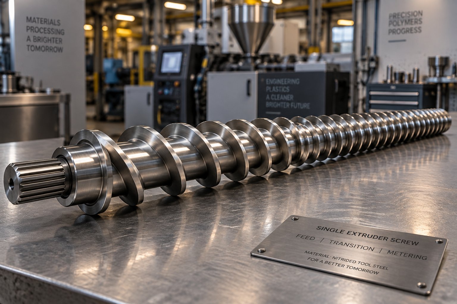
Why Polypropylene Demands a Specialized Extruder Screw
Imagine running your PP line with a general-purpose screw and pulling extrudate riddled with unmelted pellets, gels, or subtle discoloration you cannot trace. You tweak barrel temperatures, adjust screw speed, even swap resin lots - yet the problems persist. The root cause is almost always the same: the extruder screw was never designed for polypropylene in the first place.
Most extrusion references treat PP as interchangeable with polyethylene or polystyrene. It is not. PP is a semi-crystalline polymer with a melting temperature in the narrow 160-170 °C range, low melt strength, and a sharp solid-to-melt transition that punishes imprecise screw geometry. A plastic extruder screw built for broad-melting amorphous resins simply cannot deliver the controlled, gradual energy input PP requires. The result? Pressure surges, incomplete melting, thermal degradation from excessive shear, and inconsistent output that no amount of downstream tuning can fix.
Why Generic Screw Designs Fail with Polypropylene
A standard general-purpose screw typically features a moderate compression ratio and transition zone length calibrated for resins that soften gradually over a wide temperature window. PP behaves differently. Its crystalline regions resist melting until they hit a relatively precise threshold, then convert rapidly. When a screw's compression zone is too short or too aggressive for this behavior, you get two equally damaging outcomes: unmelted solids pushed into the metering zone, or localized overheating that triggers chain scission and irreversible molar mass degradation. Processors often mistake these for material defects when the real culprit is a geometry mismatch between the screw and the resin.
What Makes an Extruder Screw PP-Optimized
An extruder screw for PP addresses these challenges through deliberate adjustments to compression ratio, feed and transition zone proportions, flight depth progression, and mixing element selection. Every parameter must account for PP's crystalline melting behavior, its sensitivity to thermal-oxidative degradation, and its relatively low melt viscosity compared to other commodity resins.
PP's narrow melting window means screw geometry tolerances are significantly tighter than for amorphous polymers like PS or ABS. A few percentage points of compression ratio error or a slightly miscalculated transition zone length can be the difference between consistent, high-quality output and chronic defects.
This guide is built specifically for engineers, processors, and purchasing managers who need to select or specify a screw plastic extruder setup optimized for polypropylene. In the sections ahead, you will find the polymer science behind each design decision, precise geometry recommendations by PP grade and application, barrier screw comparisons, mixing section strategies for filled compounds, material selection for long screw life, and a diagnostic framework that maps common PP extrusion defects directly back to screw design causes.
Understanding PP's Semi-Crystalline Nature and Screw Design Impact
Every extrusion screw is ultimately a heat-and-pressure delivery system, and how effectively it delivers both depends on the polymer it is processing. With polypropylene, the molecular architecture itself dictates what the screw must do - and where most general-purpose designs fall short.
PP is a semi-crystalline polymer, meaning its long molecular chains organize into two coexisting structural regions. Some portions pack tightly into ordered crystalline lamellae - neatly folded, closely stacked arrangements held together by strong intermolecular forces. Other portions remain tangled in a disordered, amorphous state, more like a bowl of spaghetti. This dual structure is what gives PP its rigidity, chemical resistance, and favorable wear properties. But it also creates a processing challenge that directly shapes how a screw extruder must be designed.
The crystalline regions resist melting until they reach a fairly precise energy threshold. When that threshold is crossed - typically in the 160-170 °C range - those ordered structures collapse rapidly. Unlike amorphous polymers such as ABS or polystyrene, which gradually soften across a broad temperature window, PP transitions from solid to melt over a comparatively narrow band. This sharp melting transition is the single most important factor influencing extrusion screw design for PP.
Semi-Crystalline Melting Behavior and the Compression Zone
Picture what happens inside the barrel as PP pellets move from the feed zone into the compression (transition) zone. In this region, the channel depth decreases progressively, compacting the material and generating the shear heat that - combined with barrel heating - drives melting. For a polymer with a gradual softening curve, the compression zone can be somewhat forgiving. The material softens incrementally, and minor geometry variations do not cause dramatic process swings.
PP offers no such forgiveness. Its crystalline regions remain essentially solid right up to the melting threshold, then convert to a low-viscosity melt relatively abruptly. If the compression zone is too short or the extrusion screw compression ratio is too aggressive, that sudden solid-to-melt conversion creates localized pressure surges and output instability. You will see it as cyclic variation in extrudate dimensions - the classic "surging" defect that frustrates operators and wastes material.
Conversely, if the transition zone is too long or too gentle, PP pellets can survive into the metering section without fully melting. Those unmelted solids show up as visible specks, gels, or weak points in the finished product. The extrusion screw must thread a narrow needle: compressing firmly enough to ensure complete melting before the metering zone, yet gradually enough to avoid the pressure spikes that accompany PP's abrupt phase change.
Two parameters carry the heaviest load in solving this challenge:
- Compression ratio - the ratio of the feed zone channel volume to the metering zone channel volume. For PP, this ratio must be high enough to fully compact and melt the crystalline structure, yet controlled to prevent the shear overheating that degrades this thermally sensitive resin.
- Transition zone length - the number of screw diameters over which the channel depth decreases. PP benefits from a transition zone that is neither too abrupt nor excessively drawn out, allowing the crystalline regions to melt progressively rather than catastrophically.
Getting these two parameters right is the foundation of every PP-optimized screw design. Every other geometric choice - flight depth, pitch, L/D ratio - builds on this foundation.
How PP Differs from Amorphous Polymers in Screw Processing
Why can't you simply use the same screw for PP that works perfectly well for polystyrene or ABS? The answer lies in how differently these polymer families behave at the molecular level during extrusion.
Amorphous polymers have randomly arranged molecular chains with no ordered crystalline regions. They do not have a defined melting point. Instead, they pass through a glass transition temperature and progressively soften as heat increases. This gradual transition means a screw extruder with a moderate compression ratio and a standard transition zone length can produce acceptable melt quality across a relatively broad processing window.
Semi-crystalline polymers like PP and PE behave fundamentally differently. Their crystalline structure requires a discrete amount of energy - the heat of fusion - to break down the ordered lattice before the material can flow. This energy requirement creates the sharp melting transition that demands tighter screw geometry tolerances. PP is especially demanding because it also has relatively low melt viscosity once melted, which means it is prone to backflow over the screw flights if metering zone clearances are not properly maintained.
The table below highlights these key differences and their practical implications for screw design. Notice how the recommended compression ratio ranges and design priorities shift significantly from one polymer family to another.
| Property | PP (Polypropylene) | PE (Polyethylene) | PS (Polystyrene) |
|---|---|---|---|
| Polymer Structure | Semi-crystalline | Semi-crystalline | Amorphous |
| Melting Behavior | Sharp transition, ~160-170 °C | Sharp transition, ~120-135 °C (varies by density) | Gradual softening, no defined melting point |
| Recommended Compression Ratio | 2.5-4.0 | 3.0-4.0 | 2.0-4.0 |
| Thermal Degradation Sensitivity | Moderate to high - susceptible to oxidative chain scission at elevated temperatures | Moderate - crosslinking and degradation at high shear | Lower - broader safe processing window |
| Melt Viscosity | Relatively low once melted; sensitive to shear rate | Moderate; varies significantly with density grade | Higher and more stable; less shear-sensitive |
| Key Screw Design Priority | Gradual but purposeful compression zone; avoid abrupt solid-to-melt transition | Sufficient compression for high crystallinity; adequate mixing for density uniformity | Standard transition works well; focus on melt temperature uniformity |
The compression ratio data for PP (2.5-4.0) and PS (2.0-4.0) might look similar at first glance, but the design intent behind those numbers is completely different. For PS, the broad range reflects flexibility - you can go lower because the material softens gradually and forgives geometric compromises. For PP, you need to land within that range precisely because undershooting leaves unmelted crystallites, while overshooting generates the excessive shear heat that triggers degradation.
This distinction explains why a screw that performs beautifully on ABS - with its compression ratio of just 1.6-2.5 - will almost certainly produce defects when processing PP. The compression is simply insufficient to break down PP's crystalline structure, and the transition zone geometry is not calibrated for PP's abrupt melting behavior.
These molecular-level differences set the stage for specific geometric decisions. The question is no longer whether PP needs a specialized screw, but exactly how each dimension - L/D ratio, flight depth, pitch, and zone distribution - should be tuned to match PP's unique processing demands.
Critical Screw Geometry Parameters for PP Extrusion
Knowing that PP's semi-crystalline structure demands tighter screw geometry is one thing. Translating that knowledge into specific dimensional decisions - L/D ratio, flight depths, compression ratio, pitch - is where the real engineering begins. Each of these parameters solves a distinct PP processing challenge, and getting even one wrong can cascade into defects that barrel temperature adjustments alone will never fix.
Think of extruder screws as precision instruments rather than generic conveying hardware. For PP, every geometric dimension must balance three competing demands: deliver enough energy to fully melt the crystalline structure, avoid the excessive shear that triggers thermal degradation, and maintain the output consistency that downstream equipment depends on. Here is how each critical parameter contributes to that balance.
L/D Ratio and Zone Length Distribution for PP
The PP challenge: PP's sharp melting transition means the screw needs adequate length to complete melting and homogenize the melt - without holding material in the barrel so long that thermal-oxidative degradation begins. Too short a screw, and unmelted pellets reach the die. Too long, and the extended residence time at elevated temperatures attacks PP's molecular weight.
The design solution: PP generally benefits from L/D ratios in the 24:1 to 30:1 range. An L/D of 24:1 is a common starting point for standard PP homopolymer applications, while more demanding processes - high-output film lines, filled PP compounds, or applications requiring exceptional melt uniformity - often push toward 28:1 or 30:1. The additional length provides room for a properly proportioned transition zone and, where needed, a mixing section without sacrificing metering zone performance.
Zone length distribution within that overall L/D is equally important. For PP, a typical allocation looks like this:
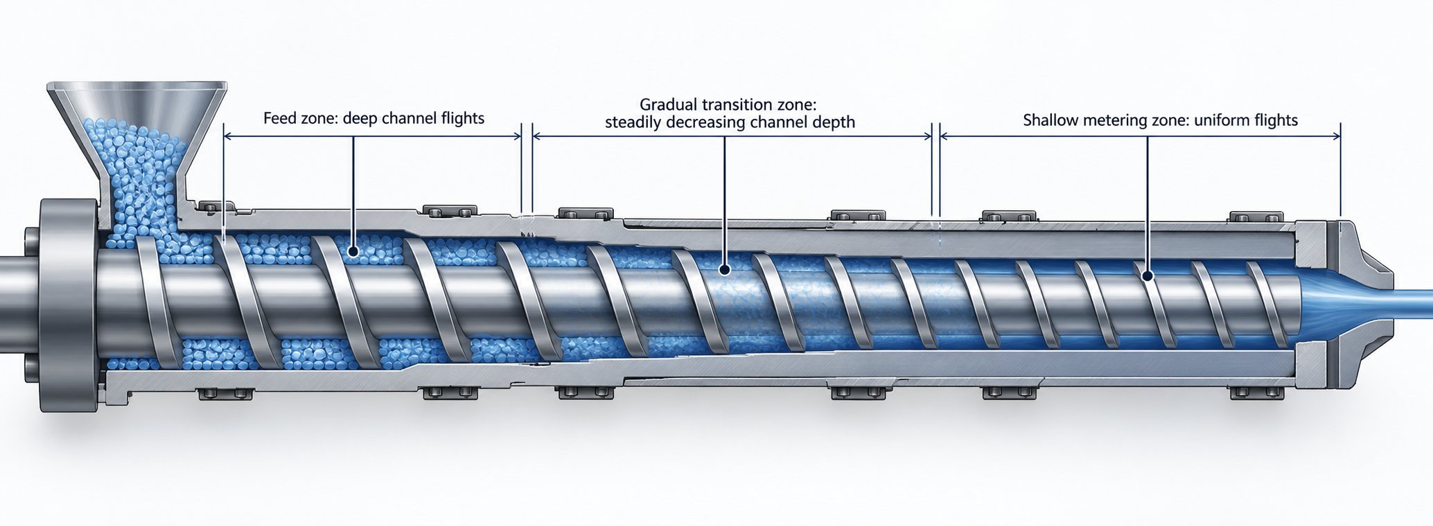
- Feed zone: approximately 4-6 diameters (roughly 20-25% of effective screw length) - long enough to establish consistent solids conveying and prevent feed starvation.
- Transition (compression) zone: approximately 6-10 diameters (roughly 25-35%) - deliberately extended compared to amorphous resin screws, giving PP's crystalline regions time to absorb the heat of fusion gradually.
- Metering zone: approximately 6-10 diameters (roughly 25-35%) - sufficient length to stabilize melt pressure and temperature before the material reaches the die.
The transition zone deserves special attention. As Allan Griff's extrusion fundamentals emphasize, more screw length can mean more output when melting or mixing is the bottleneck. For PP, a compressed transition zone is almost always the bottleneck - extending it is one of the most effective geometry changes a processor can make.
Compression Ratio and Flight Depth Optimization
The PP challenge: PP pellets have a relatively low bulk density and moderate coefficient of friction against steel. The feed zone must accommodate these solids-handling characteristics without starving the transition zone. Simultaneously, the compression ratio must be high enough to fully collapse PP's crystalline structure into a homogeneous melt, yet not so aggressive that it generates excessive shear heat in a polymer already sensitive to thermal degradation.
The design solution: The compression ratio - the volume of the first flight divided by the volume of the last - typically falls in the 2.5:1 to 3.5:1 range for PP homopolymer. PP copolymers, with their slightly broader melting range and lower crystallinity, can often work well at the lower end of this range, around 2.5:1 to 3.0:1.
Flight depth drives these ratios. In the feed zone, a deeper channel is necessary to capture enough low-bulk-density PP pellets per revolution to maintain target throughput. Feed depths commonly range from 0.12D to 0.18D (where D is the screw barrel inner diameter). In the metering zone, the channel narrows to approximately 0.04D to 0.06D for PP homopolymer, producing the controlled shear and pressure that ensure a uniform melt.
Here is the critical nuance: compression ratio alone is an indefinite number and cannot properly describe a screw unless at least one channel depth is known. Two screws with identical 3:1 compression ratios but different absolute feed depths will process PP very differently. Always specify both the ratio and the actual depths when ordering or evaluating extruder screws.
Pitch and Helix Angle Considerations
The PP challenge: Pitch directly controls how fast material advances through the barrel per revolution, which in turn determines residence time and the shear rate imposed on the melt. PP's sensitivity to both under-processing (unmelted solids) and over-processing (thermal degradation) means pitch selection is a balancing act.
The design solution: Most PP extruder screws use a square pitch - the distance from one flight to the next equals the screw diameter - which corresponds to a helix angle of approximately 17.66 degrees. This standard geometry provides a good compromise between throughput rate and residence time for the majority of PP applications. Increasing the pitch beyond square (a steeper helix angle) boosts throughput but shortens the time material spends in each zone, risking incomplete melting. Decreasing the pitch extends residence time and can improve melt quality, but it also increases shear exposure and reduces output - a trade-off that is rarely justified unless you are processing a specialty PP grade requiring exceptionally tight thermal control.
Flight width is another often-overlooked detail. The standard guideline of approximately 10% of barrel diameter works well for PP. Wider flights consume useful screw length and generate excessive heat in the flight-to-barrel clearance, while narrower flights allow too much leakage flow - both of which undermine the precise melt control PP demands.
The table below consolidates these geometry parameters into recommended ranges for the two most common PP families. Use it as a starting specification when designing or evaluating a screw barrel set for your PP line.
| Screw Geometry Parameter | PP Homopolymer | PP Copolymer (Random/Impact) | Design Rationale for PP |
|---|---|---|---|
| L/D Ratio | 24:1 - 30:1 | 24:1 - 30:1 | Ensures complete melting and adequate residence time without excessive thermal exposure |
| Compression Ratio | 2.8:1 - 3.5:1 | 2.5:1 - 3.0:1 | Homopolymer's higher crystallinity demands more compression; copolymer's broader melt range allows lower ratios |
| Feed Zone Depth | 0.14D - 0.18D | 0.12D - 0.16D | Accommodates PP's low pellet bulk density; deeper channels prevent feed starvation |
| Metering Zone Depth | 0.04D - 0.06D | 0.045D - 0.065D | Shallow enough for adequate shear and pressure, deep enough to avoid degradation from excessive viscous heating |
| Pitch | 1.0D (square pitch) | 1.0D (square pitch) | Standard square pitch balances throughput and residence time; deviations rarely needed for commodity PP grades |
| Transition Zone Length | 6-10D | 5-8D | Extended transition prevents abrupt solid-to-melt conversion and pressure surging |
| Flight Width | ~0.10D | ~0.10D | Standard width minimizes leakage flow while avoiding excessive shear heat in the clearance |
Keep in mind these ranges represent proven starting points, not rigid rules. Actual production conditions - output targets, die resistance, filler loadings, and the specific melt flow index of your PP grade - may require fine-tuning within or slightly outside these windows. The key principle holds regardless: every dimension of the extruder screw barrel must respect PP's sharp melting behavior and limited thermal processing window.
Geometry alone, however, tells only part of the story. Even a perfectly dimensioned single-flight screw can struggle with PP's abrupt melting transition at high output rates. That limitation is precisely what led to the development of barrier screw technology - a design approach that physically separates the solid bed from the melt pool to give processors far greater control over the melting process.
Barrier Screw Designs vs Conventional Screws for PP
A perfectly proportioned single-flight screw can still fail at high output rates when processing PP. Why? Because of a phenomenon called solid bed break up. As the solid bed narrows in the compression zone, it eventually becomes too small to withstand the internal channel pressure. The remaining unmelted pellets fracture and disperse into the melt pool - and with PP's sharp crystalline melting point, those fragments do not simply dissolve away. They survive as unmelted particles or gels in the final product. Barrier screw technology was developed specifically to eliminate this problem, and it offers PP processors a powerful upgrade over conventional designs.
How Barrier Screws Solve PP's Sharp Melting Challenge
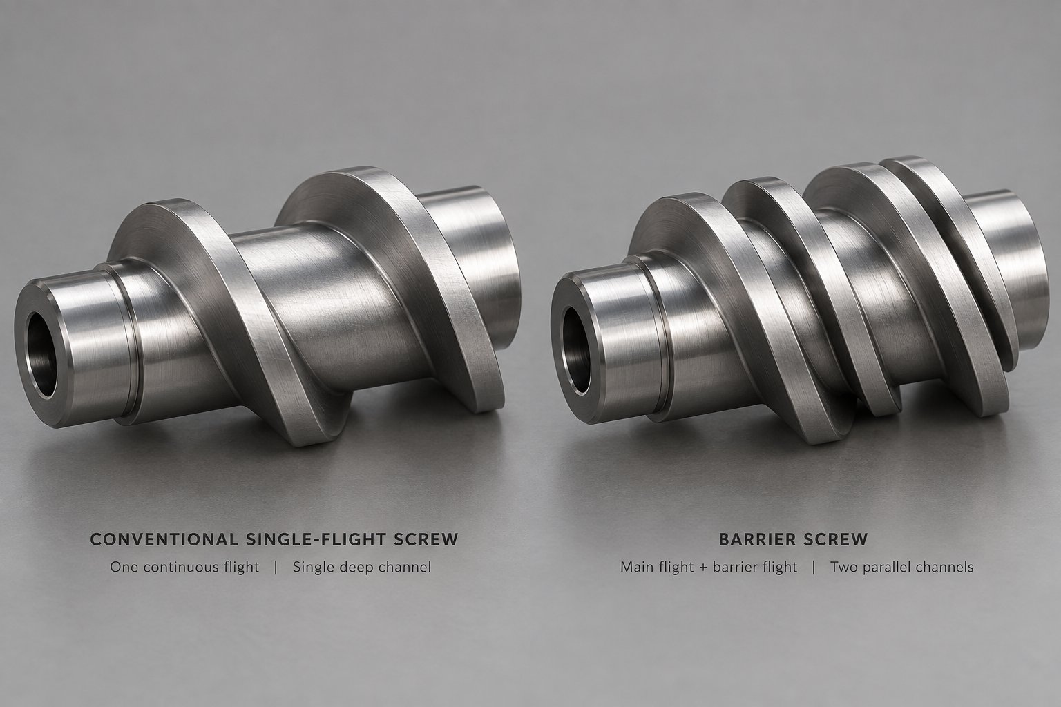
Imagine a conventional single-flight screw as a one-lane highway where solid pellets and molten polymer share the same channel. As the solid bed melts, the melt pool grows and physically crowds the remaining solids into an ever-narrower strip. Eventually, the solid bed ruptures. For amorphous resins that soften gradually, this is manageable. For PP - with its narrow melting window and low melt viscosity - it is a recipe for quality defects.
A barrier screw introduces a secondary flight, called the barrier flight, into the transition section. This additional flight creates two distinct channels: a primary (solids) channel and an auxiliary (melt) channel. The barrier flight is undercut just enough to allow molten polymer to flow over it into the melt channel, but tight enough to prevent unmelted solids from crossing. The result is clean separation - solids stay in their channel and continue melting against the barrel wall, while the melt accumulates separately without interference.
This mechanism directly addresses PP's core processing challenge. The primary channel continuously shrinks in cross-sectional area (much like a conventional transition zone), maintaining compressive pressure on the solid bed. Meanwhile, the auxiliary channel grows to accommodate the increasing volume of melt. Because the solid bed remains uncontaminated by melt pool accumulation, the area available for melting stays significantly larger than in a conventional screw of the same diameter and L/D. Solid bed break up is effectively eliminated - even at high screw speeds where conventional designs would struggle.
Two primary barrier screw families dominate PP processing:
- Maddock-style (fluted barrier) designs - Originally developed for polyolefin processing and refined over decades, these use straight or slightly angled barrier flights. Extrusion legend Bruce Maddock's work at Union Carbide helped establish these designs as the standard for crystalline polymers. They excel at controlled, high-shear melting and are well-suited for PP lines where melt temperature consistency is the top priority.
- Spiral barrier designs - These feature helically wrapped barrier flights that create a more gradual melt-solid separation. Spiral designs tend to offer smoother pressure profiles along the screw length, reducing the pressure pulsation that can cause output surging in PP extrusion. They are often preferred for high-output PP film and sheet lines where dimensional stability is critical.
For PP specifically, spiral barrier screws have gained favor because their geometry matches the gradual-but-purposeful compression philosophy that PP's crystalline melting behavior demands. The helical barrier flight provides a longer effective separation path, giving PP's crystalline regions more time and surface area to absorb the heat of fusion before crossing into the melt channel.
When to Choose a Barrier Screw Over a Conventional Screw for PP
Not every PP application warrants the added complexity and cost of a barrier design. The decision depends on your output requirements, quality standards, and the range of PP grades you process. Here is a practical framework.
Barrier screws deliver the greatest advantage in high-output PP extrusion where melt quality directly impacts product performance. Think blown or cast film lines running at maximum throughput, sheet extrusion where surface defects are commercially unacceptable, and pipe production where pressure-rating consistency depends on homogeneous melt. In these screw extruders, the improved melting control of a barrier design translates directly into fewer rejects, tighter dimensional tolerances, and the ability to push output higher without sacrificing quality.
A conventional single-flight screw remains a viable choice when output demands are moderate, when you frequently switch between very different PP grades (or between PP and other resins), or when budget constraints rule out the higher upfront investment in a precision extrusion screw barrel set. Conventional screws are also easier to clean and less sensitive to grade-to-grade variations in pellet size and bulk density.
Advantages of Barrier Screws for PP
- Improved melt homogeneity - physical separation of solids and melt eliminates the unmelted particles and gels that plague PP processing on conventional screws
- Higher output at lower screw speed - the increased melting capacity allows processors to achieve target throughput without the excessive RPM that drives up melt temperature and degradation risk
- Reduced gel count - critical for PP film applications where optical clarity and printability depend on a clean, gel-free melt
- More stable output pressure - the controlled melting profile minimizes the pressure surges that cause dimensional variation in extruded PP products
- Better energy efficiency - viscous heat dissipation becomes the primary melting mechanism rather than relying largely on conductive heat transfer, reducing barrel heater energy consumption
Limitations of Barrier Screws for PP
- Higher initial cost - the secondary flight and precision clearances make barrier screw and barrel sets more expensive to manufacture than conventional designs
- Less flexibility across multiple PP grades - barrier flight clearance is optimized for a specific melt viscosity range, so running vastly different MFI grades on the same screw can compromise performance
- More complex design and sourcing - barrier geometry must be carefully matched to the specific PP grade, output target, and die configuration, requiring closer collaboration with the screw manufacturer
- Cleaning difficulty - the dual-channel structure makes purging and material changeovers more time-consuming, particularly when switching between PP and other polymer families
- Sensitivity to contamination - as noted by extrusion expert Jim Frankland, even a relatively low percentage of higher-melting contaminants can plug the tight barrier flight clearances, causing unstable and reduced output
This last point deserves emphasis for processors running recycled PP. Post-consumer or post-industrial regrind may contain small amounts of higher-melting contaminants - PET fragments, nylon layers from multilayer packaging, or crosslinked material. These contaminants will not soften or flow over the barrier flight clearance, potentially clogging the screw. If your PP line regularly processes recycled feedstock with variable contamination, a conventional screw with appropriate mixing elements may actually outperform a barrier design in terms of reliability.
The barrier-versus-conventional choice is only one dimension of the screw specification puzzle. Regardless of which design you choose, the specific PP grade you run - homopolymer, random copolymer, or impact copolymer - introduces an entirely separate set of processing demands that further shape screw geometry, mixing requirements, and operational parameters.
Matching Screw Design to PP Grade and Application
You have the geometry parameters dialed in, you understand the barrier-versus-conventional trade-off - but here is a question that catches many processors off guard: which PP are you actually running? Not all polypropylene is created equal, and the specific grade on your production schedule changes what the screw must do at a fundamental level. A screw optimized for stiff, highly crystalline homopolymer will underperform on a soft impact copolymer, and vice versa. This is the gap most extrusion guides ignore entirely.
Polypropylene falls into three main families, each with a distinct molecular architecture that directly shapes screw design decisions: homopolymer (H-PP), random copolymer (PP-R), and impact copolymer (ICP or PP-B). Understanding how these families differ is not just academic - it is the difference between a screw that processes cleanly and one that fights you every shift.
PP Homopolymer vs Copolymer Screw Requirements
Homopolymer PP (H-PP) contains only propylene monomer and achieves the highest crystallinity of the three families - typically 50-70%. That high crystallinity means a sharper, more defined melting point (around 160-165 °C) and a larger heat of fusion that the screw must supply. From a screw design perspective, this translates into a non-negotiable requirement: the compression zone must deliver enough energy, distributed gradually, to fully collapse those tightly packed crystalline lamellae without generating localized hot spots that trigger oxidative degradation.
In practice, homopolymer PP demands compression ratios at the upper end of the PP range - typically 2.8:1 to 3.5:1. The transition zone should be long enough to prevent the abrupt solid-to-melt conversion discussed in earlier sections, usually 6 to 10 screw diameters. Metering zone depth stays relatively shallow (0.04D to 0.06D) to build adequate discharge pressure and ensure consistent output. Because homopolymer PP has the lowest melt viscosity of the three families once it melts, flight-to-barrel clearance must be tight to minimize leakage flow that robs output and disrupts pressure stability.
Random copolymer PP (PP-R) introduces small amounts of ethylene comonomer - typically up to 6% - randomly distributed along the polymer chain. These ethylene units disrupt the regularity of the crystalline structure, lowering both crystallinity and melting temperature. PP-R melts at roughly 135-150 °C, and it softens over a broader temperature window compared to homopolymer. This broader melting range is a gift to screw designers: the compression zone can be slightly shorter and the compression ratio slightly lower (2.5:1 to 3.0:1) without risking unmelted solids. Random copolymer is, in many ways, the most forgiving PP grade to extrude.
However, PP-R's lower melting point also means the screw and barrel temperature profile must be set carefully to avoid premature melting in the feed zone, which would destroy the solid bed conveying mechanism that drives throughput. If your feed zone runs too hot, PP-R pellets soften and stick to the screw root instead of being pushed forward by the flights - a classic feed problem that operators often misdiagnose as a hopper bridging issue.
Impact copolymer PP (ICP) is the most complex of the three families. It features a heterophasic structure - a PP homopolymer matrix with a dispersed ethylene-propylene rubber (EPR) phase. The rubber phase is what gives ICP its superior impact strength, even at low temperatures. But that rubber phase also introduces a unique screw design demand: the screw must not only melt the crystalline PP matrix but also thoroughly disperse the rubber domains to achieve uniform mechanical properties throughout the extrudate.
This means impact copolymer processing places a premium on mixing capability. A simple metering screw - even one with geometry perfectly tuned for PP homopolymer - will often produce ICP parts with inconsistent impact strength because the rubber phase remains poorly distributed. Injection molding screws and barrels running ICP grades benefit significantly from dedicated mixing sections, such as Maddock mixers or fluted mixing elements, positioned after the metering zone. In extrusion applications, barrier screws with integrated distributive mixing elements provide the best combination of melting control and rubber-phase dispersion.
The compression ratio for ICP typically falls between the homopolymer and random copolymer ranges - around 2.7:1 to 3.2:1. The rubber phase acts as an internal lubricant during melting, slightly reducing the shear energy needed compared to straight homopolymer. The real challenge is not melting but mixing, which is why ICP screw profiles tend to dedicate more screw length to mixing sections and less to an extended transition zone.
Application-Specific Screw Profiles for PP
Grade selection tells you what the material needs. Application tells you what the product needs. A PP homopolymer destined for biaxially oriented film demands a very different screw profile than the same resin pelletized for distribution. Each end-use application imposes its own hierarchy of priorities - melt homogeneity, output rate, shear sensitivity, pressure stability - and the injection screw or extrusion screw profile must reflect those priorities.
Screw speed and back pressure targets also shift dramatically across applications. A fiber spinning line might run at high RPM with moderate back pressure to achieve the narrow melt temperature distribution that prevents denier variation. A pipe line, by contrast, runs at lower speed with higher back pressure to maximize output consistency and maintain the wall thickness uniformity that pressure ratings depend on. These operational parameters are not independent of screw design - they interact with it. A screw geometry that works beautifully at 60 RPM for pipe may produce degraded melt at the 120 RPM a film line demands.
Here is how the major PP applications map to recommended screw profile characteristics:
- PP blown and cast film - Film extrusion is the most demanding PP application in terms of melt quality. Any unmelted particle, gel, or temperature variation shows up as a visible defect, a thin spot, or a break on the winding roll. The screw profile must prioritize melt homogeneity and low shear degradation above all else. Barrier screw designs with spiral barrier flights are the preferred choice, often paired with a downstream distributive mixing element. Screw speed is kept moderate to limit viscous heating, and L/D ratios of 28:1 to 30:1 provide the extra length needed for thorough melting and mixing without pushing residence time to degradation territory.
- PP pipe and profile - Output consistency and pressure stability are king. Dimensional tolerances for pressure-rated pipe are tight, and any surging or pressure fluctuation translates directly into wall thickness variation. Conventional metering screws with properly proportioned compression zones perform well here, though barrier designs offer advantages at higher throughput rates. Compression ratios lean toward the middle of the PP range (3.0:1 to 3.5:1 for homopolymer), and the metering zone is kept long - eight to ten diameters - to stabilize discharge pressure. Screw speeds are typically moderate, and grooved feed sections are common to ensure consistent solids conveying.
- PP fiber and monofilament - Fiber spinning demands an exceptionally narrow melt temperature distribution - often within +/- 2 °C across the entire melt stream. Even small temperature variations cause denier inconsistency and break frequency spikes at the spinneret. Screw profiles emphasize high-shear mixing, usually through aggressive dispersive mixing elements, to homogenize the melt thermally. L/D ratios of 28:1 or higher give the melt time to equilibrate. The injection screw equivalent in fiber spinning setups needs tight metering clearances and often runs at higher RPM to generate the shear mixing energy required for thermal uniformity.
- PP sheet - Sheet extrusion sits between film and pipe in its demands. Surface quality must be excellent - any imperfection is visible and aesthetically unacceptable for thermoforming applications. Yet output rates are high, and the die width means any cross-die temperature variation creates thickness non-uniformity. Balanced compression with good mixing is the formula. Compression ratios in the 2.8:1 to 3.2:1 range work well, and a distributive mixing section before the metering zone helps even out thermal gradients. Injection molding screws and barrels designed for PP sheet thermoforming feedstock follow similar principles when the sheet is produced in-line from pellets.
- PP recycling and pelletizing - Recycled PP presents the widest variability of any application: mixed grades, fluctuating moisture content, contamination from labels, adhesives, or other polymers. The screw must tolerate this variability without plugging or producing excessive rejects. Conventional screw designs with robust mixing sections outperform barrier screws here because barrier flight clearances are too sensitive to contamination. Compression ratios can be slightly more aggressive (3.0:1 to 3.5:1) to ensure complete melting of mixed-crystallinity feedstock. Extended L/D ratios - 48:1 or higher on twin-screw extruders - with multi-stage vacuum degassing ports handle the volatile removal that recycled PP demands. For single-screw pelletizing lines, an L/D of 28:1 to 30:1 with a vented barrel design is a practical minimum.
Notice the pattern across all five applications: the screw profile always reflects a trade-off between melting thoroughness, mixing intensity, shear sensitivity, and output rate. No single screw geometry handles every PP application optimally, which is why processors running multiple product lines often maintain dedicated screws for each - or invest in modular screw designs that allow section-by-section reconfiguration.
Grade and application together define what the screw must accomplish. Yet there is a third variable that reshapes the design equation just as dramatically: what you put into the PP. Fillers, pigments, UV stabilizers, nucleating agents - each additive changes the effective melt rheology and places its own demands on the mixing section. That mixing section is where many PP processors unknowingly leave quality on the table.
Mixing Section Design for PP Additives and Fillers
A screw with textbook geometry and the right compression ratio can still produce PP parts with streaky color, uneven filler distribution, or inconsistent mechanical properties. Why? Because geometry handles melting - but it is the mixing section that handles everything you put into the PP. And in modern PP processing, you are almost always putting something in: color masterbatch, talc for stiffness, calcium carbonate for cost reduction, glass fiber for strength, nucleating agents for faster cycle times, UV stabilizers for outdoor durability. Each of these additives has its own particle size, agglomerate strength, and dispersion requirement. If the mixing section is underspecified - or missing entirely - those additives never reach the uniform distribution your product demands.
This is one of the most overlooked causes of quality problems in filled PP extrusion. Processors blame the masterbatch supplier, the filler grade, or the compounding house - when the real culprit is a screw that simply lacks the mixing capability to do its job.
Distributive and Dispersive Mixing Elements for PP
Mixing in a single-screw extruder falls into two fundamentally different categories, and understanding the distinction is essential for specifying the right elements.
- Dispersive mixing subjects the melt to high shear stress to break apart agglomerates - clumps of filler particles or pigment that are held together by surface forces. Think of it as brute-force particle size reduction. Dispersive mixing is critical when you need to break down tightly bound agglomerates, such as carbon black clusters, poorly dispersed nucleating agents, or glass fiber bundles that must be separated to individual filaments.
- Distributive mixing spreads already-separated particles or melt components uniformly throughout the polymer matrix by repeatedly dividing and recombining the melt stream. No extreme shear is involved - just spatial rearrangement. This is what you need for homogenizing color, evening out thermal gradients, and ensuring that well-dispersed filler particles are spread uniformly rather than concentrated in pockets.
Most filled PP formulations require both. The filler agglomerates must first be broken apart (dispersive), then the individual particles must be spread evenly through the melt (distributive). A screw that only provides one type leaves you with either broken-up particles stuck in clumps, or nicely distributed clumps that never got broken apart in the first place. Neither outcome produces acceptable parts.
Several common mixing element designs address these needs, each with different strengths for PP processing:
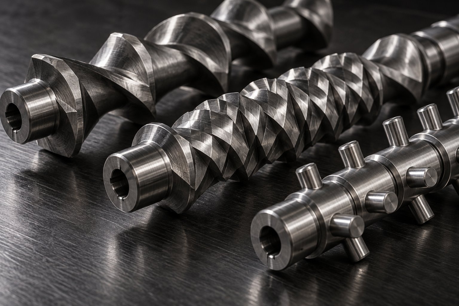
- Maddock (fluted) mixers - These are the workhorses of dispersive mixing on single-screw extruders. The melt enters inlet channels and must pass over a clearance area (the barrier) to reach the outlet channels. That clearance imposes high shear on the melt, breaking apart agglomerates. Newer spiral Maddock designs combine features of the original Maddock and Egan styles, making them the most widely used today. They work well for PP applications requiring aggressive pigment or additive dispersion, but they add melt temperature and pressure drop - a concern for thermally sensitive PP grades.
- Pineapple mixers - These elements divide the melt at varying angles for chaotic mixing, creating convergent flow paths that are exceptionally effective for color masterbatch distribution in PP. They excel in distributive mixing and are a go-to choice when uniform color dispersion is the primary goal.
- Pin mixers - Rows of pins protruding from the screw root divide the melt stream exponentially with each successive row. As extrusion expert Jim Frankland notes, pin mixers minimize the restrictions of laminar flow and can mix materials of substantially varying viscosity by creating an essentially infinite number of layers. Their disadvantage is a potentially substantial pressure drop, which must be factored into the overall screw and die design.
- Blister rings - These simple restrictive elements force the entire melt stream through a narrow annular gap between the screw and barrel wall. They provide moderate dispersive mixing and are often used in combination with other elements rather than as standalone mixers. For lightly filled PP, a blister ring ahead of a distributive mixer can provide adequate dispersion at lower cost and complexity.
For barrier screws processing PP, distributive mixers are usually the better choice downstream of the barrier section. The barrier flight has already completed the melting work, so adding a high-shear dispersive mixer would needlessly increase melt temperature, reduce output due to added pressure drop, and waste energy. A distributive mixer - Saxton, pineapple, or pin style - homogenizes temperature and additive distribution without these penalties. The exception is when specific dispersive work is needed on particles small enough to pass through the barrier section unrefined, such as fine filler agglomerates or nucleating agent clusters.
How PP Fillers and Additives Change Screw Design Requirements
Adding fillers to PP does not just change what the mixing section must do - it changes the entire screw design equation. When you load 20-40% mineral filler into a PP compound, three things happen simultaneously that a screw designer must account for.
First, the effective melt viscosity increases. Fillers like talc and calcium carbonate raise the viscosity of the PP melt, which actually helps pumping stability in the metering zone but also generates more viscous heat. If the screw geometry was designed for neat PP, the additional viscous heating in a filled compound can push melt temperature above the degradation threshold - a problem that manifests as barrel temperature overrides in the middle zones.
Second, the filler does not melt or compress. As Timothy Womer explains, since the filler takes up volume in the screw channels without changing its volume due to temperature, channel depths must account for that fact. For example, unfilled PP typically uses a compression ratio of 3.5:1 to 3.75:1, whereas a 40% talc-filled PP compound works better with a reduced ratio of 2.75:1 to 3.25:1. Ignoring this adjustment leads to excessive compression, overheating, and accelerated wear.
Third, abrasive fillers attack screw surfaces. Mica and glass fiber cause aggressive abrasive wear, particularly in the feed section where the resin is still in pellet form and fillers near the pellet surface rub directly against unprotected steel. Mineral fillers like talc and calcium carbonate are less aggressive but still cause measurable wear over time, especially at high loadings. Flight clearances open up as wear progresses, allowing more leakage flow - which in turn reduces output and mixing effectiveness in a self-reinforcing cycle.
The table below maps common PP additives to their specific effects on screw design. Use it as a quick reference when specifying or evaluating a twin screw barrel or single-screw setup for compounded PP.
| PP Additive | Typical Loading | Primary Mixing Need | Wear Impact | Recommended Mixing Element |
|---|---|---|---|---|
| Talc | 10-40% | Distributive (platelet orientation matters) | Moderate abrasive wear; increases with loading | Pineapple or Saxton mixer; reduced compression ratio |
| Calcium Carbonate | 10-50% | Distributive (uniform spatial distribution) | Mild to moderate abrasive wear | Pin mixer or pineapple mixer; generous barrier flight gap if using barrier screw |
| Glass Fiber | 10-40% | Distributive with minimal fiber breakage | High abrasive wear, especially in feed and transition zones | Low-shear distributive mixer; avoid aggressive dispersive elements that break fibers |
| Color Masterbatch | 1-5% | Distributive (uniform color with no streaks) | Negligible | Pineapple mixer (chaotic mixing excels at color); pin mixer for difficult-to-disperse pigments |
| Nucleating Agents | 0.1-1% | Dispersive first (break agglomerates), then distributive | Negligible | Maddock dispersive mixer followed by distributive element; or spiral Maddock for combined effect |
| UV Stabilizers | 0.1-1% | Distributive (uniform protection requires even distribution) | Negligible | Any distributive mixer; Saxton or pin style adequate at low loadings |
A few critical details deserve emphasis. Glass fiber-reinforced PP presents a unique dilemma: you need enough mixing to separate fiber bundles and distribute them evenly, but excessive shear breaks fibers and destroys the mechanical properties they were added to provide. This is why aggressive dispersive mixers are typically avoided for glass-filled PP. Low-intensity distributive elements that divide and recombine the melt without imposing extreme shear stress are the better path. Twin screw and barrel systems, including used twin screw extruder setups common in compounding operations, inherently provide more gentle and controllable mixing through modular screw element configurations - but on single-screw production lines, the mixing element choice becomes even more critical because you only get one pass.
Nucleating agents represent the opposite challenge. These additives are used at very low concentrations (often below 0.5%), and their effectiveness depends entirely on achieving sub-micron dispersion throughout the PP matrix. Undispersed agglomerates act as defect points rather than nucleation sites. A dispersive mixing element - Maddock style or blister ring - upstream of a distributive mixer provides the two-stage approach these demanding additives require.
The broader lesson is straightforward: an underspecified mixing section is one of the leading causes of poor additive dispersion and inconsistent part quality in filled PP extrusion. Getting the screw geometry right - compression ratio, L/D, zone lengths - is necessary but not sufficient. The mixing section is where additive performance is made or broken, and it must be designed with the same application-specific precision as every other screw parameter.
Mixing elements, fillers, and high throughput all share one consequence: they accelerate wear. And wear changes everything - clearances open, mixing effectiveness drops, output falls, and melt quality deteriorates. The materials your screw and barrel are made from determine how long your carefully specified geometry actually performs to spec, which brings metallurgy and surface engineering squarely into the design conversation.
Screw and Barrel Materials for Long-Life PP Processing
Every geometric parameter discussed so far - compression ratio, flight depth, barrier clearance, mixing element design - performs to specification only as long as the screw and barrel maintain their original dimensions. The moment wear opens up flight-to-barrel clearances, your carefully optimized extruder screw for PP starts behaving like a general-purpose screw with a geometry nobody designed. Output drops, leakage flow increases, mixing effectiveness deteriorates, and melt quality slides. As industry experts note, these changes are usually incremental and go unnoticed until they dramatically impact part quality or productivity.
PP is not the most punishing polymer on screw surfaces - that distinction belongs to glass-fiber-filled engineering plastics. But unfilled PP is far from harmless, and the moment you introduce mineral fillers, glass fiber reinforcement, or recycled feedstock with metal contaminants, the wear equation changes dramatically. Choosing the right base material, surface treatment, and barrel liner is what separates extruder barrels that last years from those that need replacement in months.
Base Material Options for PP Extrusion Screws
The base steel determines the screw's structural integrity, machinability, and compatibility with surface hardening treatments. Three main categories cover the vast majority of PP applications, and the right choice depends almost entirely on what you are feeding into the extruder.
Nitrided alloy steel is the standard workhorse for unfilled and lightly filled PP processing. Steels like 38CrMoAlA (or the equivalent SACM645 and EN41B grades) are specifically formulated for gas nitriding - a thermochemical process that diffuses nitrogen atoms into the steel surface, creating a hardened case typically reaching 55-60 HRC. For processors running neat PP homopolymer, random copolymer, or PP with low concentrations of non-abrasive additives like UV stabilizers or nucleating agents, nitrided screws deliver reliable performance at an economical price point. The nitrided layer also provides moderate corrosion resistance - adequate for standard PP processing but potentially insufficient when acidic additives or flame retardants are involved.
The limitation? Nitriding produces a hardened case that is only a fraction of a millimeter deep. Once abrasive fillers wear through that case, the softer base steel underneath erodes rapidly. If you are running 20%+ talc-filled PP or any glass-fiber-reinforced grade, a nitrided screw will likely reach its wear limit far sooner than the production economics justify.
Bimetallic construction raises the bar significantly. A bimetallic screw uses a standard alloy steel body with a wear-resistant alloy overlay - typically tungsten carbide, nickel-based alloy, or cobalt-based alloy - applied to the flight lands and sometimes the root surfaces. This overlay can achieve hardness levels of 62-70 HRC, far exceeding what nitriding alone can deliver. For mineral-filled PP compounds (talc, calcium carbonate at loadings above 15-20%) and glass-fiber-reinforced PP, bimetallic construction is the practical minimum for acceptable screw life.
The higher initial cost of a bimetallic screw is offset by dramatically longer service intervals. Processors running abrasive PP compounds often find that bimetallic screws last three to five times longer than their nitrided counterparts, reducing total cost of ownership even before you factor in the avoided production downtime for screw changes.
Tool steel and specialty alloys occupy the top tier. Materials like D2, CPM 9V, or powder metallurgy tool steels offer exceptional wear resistance and toughness for the most demanding PP applications - high-loading glass fiber compounds, recycled PP streams with metal contamination, or production environments where screw changes are extremely costly due to machine size or configuration. These materials are typically reserved for screws where the cost of unplanned downtime far exceeds the premium for a high-performance alloy.
Surface Treatments and Coatings That Extend Screw Life
Base material selection sets the foundation. Surface treatments and coatings add another layer of protection - sometimes literally - that can extend the useful life of an extruder barrel and screw set considerably. Here are the primary options and where each fits in PP processing:
- Gas nitriding - The most common and cost-effective treatment. Best suited for unfilled PP, PP with color masterbatch only, or lightly filled PP at moderate throughput rates. Provides good general wear resistance and dimensional stability with minimal distortion of the finished screw geometry.
- Chrome plating - Adds a thin, hard layer that improves corrosion resistance and provides a low-friction surface. Traditionally popular for PP processing where resin release (anti-stick) properties matter - such as PP compounds with high additive loadings that tend to build up on screw surfaces. However, environmental concerns over hexavalent chromium and performance limitations are driving the industry toward alternative coatings.
- HVOF tungsten carbide coatings - High Velocity Oxygen Fuel thermal spray deposits an extremely dense tungsten carbide layer that significantly outperforms chrome plating in both wear resistance and corrosion protection. HVOF coatings are increasingly the preferred solution for PP processors running abrasive compounds who want to avoid the environmental liabilities of chrome while gaining superior surface performance. Ideal for flight lands on screws processing glass-fiber or mineral-filled PP.
- Nickel-based and cobalt-based alloy overlays - Applied by welding or plasma transfer arc (PTA) processes, these overlays provide both abrasion and corrosion resistance. They are the go-to choice for PP lines processing compounds with flame retardants or halogenated additives that release corrosive gases at processing temperatures. The overlay thickness provides a deeper wear reserve than thin-film coatings.
- Titanium nitride (TiN) and similar PVD coatings - These thin-film coatings offer excellent surface hardness and very low friction coefficients. They work well for reducing resin adhesion on screws processing sticky PP copolymer compounds, but their thin profile limits their usefulness in highly abrasive applications.
Corrosion deserves special attention for PP processors who may not expect it. Standard PP homopolymer and copolymer are not corrosive. But PP compounds with certain flame retardants, brominated additives, or acidic stabilizers can release corrosive byproducts at elevated melt temperatures. Corrosion gradually destroys metal surfaces through chemical attack, and once the protective surface layer is compromised, mechanical wear accelerates. If your PP formulations include any potentially corrosive chemistry, specifying corrosion-resistant alloys or overlays is not optional - it is essential for predictable screw life.
The extruder feed barrel and the screw must also be considered as a matched system. A hard-coated screw running inside a softer barrel will eventually wear the barrel preferentially, while a soft screw inside a hard-lined barrel will wear the screw flights. Compatible alloy pairing between the flight hardfacing material and the barrel liner material is critical - incompatible metals increase the risk of adhesive wear (galling), where the surfaces briefly weld together and then fracture, causing accelerated damage to both components.
Barrel liner options follow a similar hierarchy to screw materials. Standard nitrided barrels work well for unfilled PP. Bimetallic barrel liners - centrifugally cast alloys with high tungsten carbide content - provide the long service life that filled PP processing demands. For processors who need application-matched extruder barrels engineered for specific PP grades and production conditions, manufacturers like NANHAIYA supply custom and replacement single screw barrels designed for pipe, film, sheet, pelletizing, recycling, and general-purpose extrusion lines. Working with a manufacturer that understands the metallurgical demands of PP-specific processing ensures that the barrel liner, screw base material, and surface treatment are specified as an integrated system rather than as isolated components.
Investing in the right material combination protects more than just the screw and barrel - it protects the geometry you spent so much effort optimizing. A worn screw is a screw with the wrong compression ratio, the wrong flight clearance, and the wrong metering depth. And those geometry deviations show up in the extrudate as the same defects - unmelted particles, surging, degradation, poor surface quality - that a PP-optimized design was supposed to eliminate. Knowing how to trace those defects back to their root causes, whether geometry, wear, or process settings, is what transforms a reactive troubleshooting approach into a systematic one.
Troubleshooting PP Extrusion Problems Through Screw Design
Your PP line is running. The barrel temperatures look right, the resin lot is consistent, and the downstream equipment checks out fine - yet the extrudate still shows defects. Unmelted specks embedded in the product. Cyclic surging that makes wall thickness wander. Discoloration that was not there last week. Before you start adjusting process settings at random, consider this: the vast majority of persistent PP extrusion defects trace back to a mismatch between screw design and the polymer's processing demands.
The geometry, wear state, and mixing capability of the screw are upstream of everything else. A barrel extruder producing bad PP melt will never be fixed by downstream tuning - you are treating symptoms while the cause sits inside the extrusion barrel, spinning at 60 RPM. This section gives you a structured diagnostic framework that links each common PP defect directly to a screw design cause and a concrete corrective action.
Unmelted Particles and Gels in PP Extrudate
Imagine inspecting a PP film sample and finding small hard specks or translucent gels scattered through the web. You might suspect contamination or a bad resin lot - but if the specks disappear when you slow the screw down and reappear when you speed back up, the screw itself is almost certainly the problem.
Unmelted particles in PP are fundamentally a melting capacity issue. PP's sharp crystalline melting transition means that any solid pellet fragment that does not receive sufficient energy in the compression zone will survive intact into the metering section. Unlike amorphous polymers that gradually soften and eventually dissolve into the surrounding melt, PP crystallites remain stubbornly solid until they absorb enough heat of fusion to collapse their lattice structure. Three screw design factors most commonly allow this to happen:
- Insufficient compression ratio - When the ratio falls below the minimum needed for PP (roughly 2.5:1), the compressive forces in the transition zone are too weak to maintain full contact between the solid bed and the barrel wall. Without that contact, conductive heat transfer from the barrel and shear heating both decline, and melting slows to the point where solids survive.
- Too-short transition zone - Even with an adequate compression ratio, cramming the entire depth reduction into four or five diameters creates an abrupt solid-to-melt conversion that PP cannot handle cleanly. The solid bed fractures before it fully melts, releasing unmelted fragments into the melt pool - the classic solid bed breakup phenomenon.
- Excessive screw speed - Higher RPM pushes material through the barrel faster, reducing the residence time available for melting. On a screw that barely completes PP melting at moderate speed, pushing output by increasing RPM predictably results in unmelted solids at the die.
The fix depends on the root cause. If the screw geometry is the issue, upgrading to a barrier design physically separates solids from melt and eliminates solid bed breakup - even at elevated throughput. If the screw geometry is adequate but worn, measuring flight-to-barrel clearance will reveal whether compression loss is the culprit. A clearance increase of just 0.1-0.2 mm per side can reduce effective compression enough to let unmelted PP through. And if the problem only surfaces at high RPM, extending the transition zone length or adding a mixing section downstream can provide the additional melting and homogenization capacity the process needs.
Melt Temperature Instability and Surging
Surging - the cyclic oscillation of output rate at constant screw speed - is one of the most frustrating PP extrusion defects because its effects propagate everywhere. Wall thickness varies. Die pressure fluctuates. Downstream equipment cannot maintain stable dimensions. Operators chase the problem with temperature adjustments, making it worse.
Mark Spalding's research at Dow demonstrates that the most common root cause for flow surging in smooth-bore extruders is improper temperatures in the solids conveying section. For PP specifically, this means the feed zone of the screw and the feed casing must be at the right temperature to maximize forwarding forces at the barrel wall while minimizing retarding friction at the screw root. When the screw root gets too hot, PP pellets soften prematurely and stick rather than convey forward, creating the intermittent solids delivery that drives output oscillation.
Screw design factors that contribute to PP surging include:
- Improper feed zone design - A feed zone that is too short does not establish stable solids conveying before material enters the compression zone. For PP, the feed section should span at least four to six screw diameters to build a consistent, well-compacted solid bed.
- Incorrect flight depth in the feed zone - Flights that are too deep for the PP pellet size and bulk density create an unstable solid bed that breaks apart and reconsolidates cyclically. Flights that are too shallow starve the compression zone, producing the same oscillating output pattern.
- Worn screw or extrusion barrel clearance - As the flight-to-barrel gap increases through wear, the screw loses pumping efficiency. The metering zone can no longer maintain stable discharge pressure, and the process becomes increasingly sensitive to any upstream variation. When wear changes geometry, melting relocates, and the process becomes unstable even if temperatures stay normal.
A practical first check: feel the feed casing. It should be warm to the touch, not hot. If it is hot, the cooling water channels may be occluded or the flow rate insufficient. Next, verify screw cooling if your extruder uses it - inadequate screw cooling is a documented cause of surging on PP lines where the screw root temperature rises above the pellet softening point. These simple physical checks often solve the problem faster than any PID tuning or barrel profile adjustment.
Surface Defects and Degradation in PP Products
Sharkskin, matte patches, discoloration, and brittleness in PP extrudate all point toward excessive mechanical energy input - usually from a screw that shears the polymer harder than its thermal stability allows. PP is particularly vulnerable because it degrades primarily through oxidative chain scission, a process that accelerates exponentially with temperature. A melt temperature just 10-15 degrees above the optimal window can cut molecular weight enough to measurably reduce impact strength and elongation at break.
Two screw geometry parameters are most frequently responsible:
- Too-tight metering depth - A shallow metering channel generates high shear rates in the gap between the screw root and the barrel wall. For PP, metering depths below approximately 0.04D push shear heating to levels that the polymer cannot tolerate at typical extrusion speeds. The result is localized overheating, which shows up as burn marks, brittle parts, odor, color shift, or black specks.
- Excessive compression ratio - A compression ratio that exceeds what PP needs (beyond 3.5:1 for homopolymer, beyond 3.0:1 for copolymer) concentrates too much mechanical work in the transition zone. The melt temperature spikes locally even though the average temperature reading at the die looks acceptable. These hidden hot spots degrade the polymer before it has a chance to cool in the metering section.
Surface roughness (sharkskin) on PP extrudate deserves a specific note. While sharkskin is often a die exit phenomenon related to wall shear stress, the screw contributes by determining the melt temperature and viscosity arriving at the die. A screw that delivers PP melt at an elevated temperature reduces viscosity and lowers die shear stress - but if that temperature comes from excessive screw shear rather than controlled barrel heating, you are trading sharkskin for degradation. The correct solution is to design the screw geometry so that the melt arrives at the die within PP's optimal viscosity window without relying on excessive mechanical energy input.
The diagnostic table below consolidates these relationships into a quick-reference format. When a defect appears on your PP line, start here to identify the most likely screw-related cause and the recommended corrective action.
| PP Extrusion Problem | Likely Screw Design Cause | Recommended Solution |
|---|---|---|
| Unmelted pellets or nibs in extrudate | Insufficient compression ratio; too-short transition zone; solid bed breakup at high RPM | Increase compression ratio to 2.8-3.5:1 for homopolymer; extend transition zone to 6-10D; upgrade to barrier screw for high-output lines |
| Output surging (cyclic flow variation) | Improper feed zone depth or length; hot screw root in feed section; worn flight-to-barrel clearance | Verify feed casing cooling; check screw cooling adequacy; measure wear and replace if clearance exceeds tolerance; extend feed zone to 4-6D minimum |
| Melt temperature variation (shot to shot or along run) | Inadequate mixing section; worn screw shifting the melt front location; metering zone too short to stabilize temperature | Add or upgrade mixing elements (Maddock or pineapple mixer); inspect screw and extrusion barrels for wear; extend metering zone to 6-10D |
| Surface defects / sharkskin | Melt arriving at die with incorrect viscosity due to screw-generated overheating or underheating | Optimize metering depth to target PP's ideal melt temperature window; adjust compression ratio to reduce excessive shear; verify die gap and land length |
| Degradation / discoloration / reduced properties | Metering depth too shallow (excessive shear); compression ratio too high; excessive residence time from oversized L/D | Increase metering depth to 0.04-0.06D range; reduce compression ratio; verify L/D is appropriate (24-30:1); lower screw RPM and compensate with optimized geometry |
| Poor additive or color dispersion | Missing or inadequate mixing section; wrong mixing element type for the additive; barrier flight clearance preventing additive passage | Add distributive mixer (pineapple or pin type) for color; add dispersive mixer (Maddock) for agglomerated fillers; verify barrier flight gap accommodates additive particle size |
Nearly every persistent PP extrusion defect traces back to one of three screw design factors: geometry that does not match PP's crystalline melting behavior, wear that has altered the original geometry, or a mixing section that is absent or undersized for the formulation being processed.
Notice a pattern in the table: many of the recommended solutions circle back to the same geometry parameters covered earlier in this guide - compression ratio, zone lengths, flight depths, and mixing element selection. That is not a coincidence. It reflects the reality that screw design is the root cause layer beneath most PP processing symptoms. Process settings like barrel temperature and screw speed are adjustment knobs - they can compensate within a narrow range, but they cannot overcome a fundamental geometry mismatch.
The practical value of this diagnostic framework increases when you combine it with regular wear monitoring. A screw that produced perfect PP extrudate when new will gradually drift toward the defect patterns described above as flight clearances open and compression effectiveness declines. Tracking specific output (kg per hour per RPM) over time gives you an early warning signal: when specific output drops by more than 5-10% from baseline, the screw geometry has likely changed enough to affect melt quality, even if the defects are not yet visible in the finished product.
Diagnosing the problem is half the challenge. The other half is deciding what to do about it - whether to retrofit your existing screw, replace it entirely, or specify a new PP-optimized screw and barrel set from scratch. That decision involves not just engineering judgment but also economics: production volume, PP grade diversity, quality requirements, and the expected return on a precision-engineered replacement.
Selecting and Sourcing the Right Extruder Screws and Barrels for PP
You have identified the defect, traced it back to a screw design cause, and know what geometry changes would fix it. The question that remains is purely practical: do you modify what you have, or start fresh with a PP-optimized replacement? That decision hinges on economics as much as engineering - and getting it wrong can mean either overspending on hardware you did not need or under-investing in a screw that never quite solves the problem.
When to Retrofit vs Replace Your Extruder Screw for PP
Retrofitting an existing screw - recutting flights, adding a mixing section, or applying a wear-resistant coating to restore clearances - makes sense when the base geometry is close to what PP demands and the screw body is structurally sound. If your current screw has an appropriate L/D ratio, a compression ratio within the 2.5-3.5:1 PP window, and the transition zone length is reasonably close to the 6-10D target, a retrofit can be the fastest and most cost-effective path to improved performance. Adding a Maddock or pineapple mixing section to a screw that melts well but disperses additives poorly is a classic retrofit success story.
Replacement becomes the smarter investment when the fundamental geometry is wrong for PP - a screw originally designed for PVC or ABS, for example, with a compression ratio below 2.0:1 and a short transition zone. Recutting such a screw to PP specifications often removes so much material that the root diameter weakens structurally. Similarly, if wear has progressed beyond the point where hard-facing or recoating can restore functional clearances, a new screw is the only path to reliable performance.
Consider these cost-benefit factors before deciding:
- Production volume - High-output PP lines recoup the cost of a precision replacement screw quickly through improved yield and reduced scrap. Low-volume operations may justify a retrofit instead.
- PP grade diversity - If you run multiple PP families (homopolymer, copolymer, filled grades), a new screw designed with the right compromise geometry - or a modular design allowing section swaps - provides flexibility that a retrofit cannot match.
- Quality requirements - Film and medical-grade PP applications demand tighter melt uniformity than pipe or recycling lines. The higher the quality bar, the more a purpose-built replacement pays for itself.
- Expected screw lifespan - Retrofitting a screw that is already halfway through its wear life gives you only half the return. A new bimetallic screw with HVOF-coated flights can deliver a decade of service on unfilled PP - manufacturers of PE or PP products may only need to replace screws every 10 years or so under normal operating conditions.
One often-overlooked point: a worn screw paired with a worn barrel is always a replacement scenario. Putting a new screw into a worn extrusion barrel - or vice versa - creates a clearance mismatch that accelerates wear on the new component. Extruder screws and barrels should be evaluated and, when necessary, replaced as a matched set.
Specifying a PP-Optimized Screw and Barrel from a Manufacturer
Whether you are ordering a replacement for a Davis Standard extruder, a retrofit for an aging single-screw line, or a completely new screw and barrel set, the quality of the result depends entirely on the quality of the information you provide. Screw manufacturers cannot optimize what they do not know about. Vague specifications like "we run PP" guarantee a generic design - the exact problem this entire guide exists to prevent.
Prepare the following information before contacting any supplier. This checklist ensures the manufacturer has everything needed to engineer a screw matched to your specific PP application:
- PP grade and MFI range - Specify the exact resin grades you run, including melt flow index values. If you process multiple grades, list them all with their relative production volume percentages so the screw designer can optimize for your primary grade while maintaining acceptable performance across the range.
- Target output rate - State your required throughput in kg/hr at the screw speed range you intend to operate. This directly determines metering zone design and whether a barrier screw is justified.
- Product type - Film, pipe, sheet, fiber, pelletizing, or injection molding. Each application imposes different priorities on the screw profile, as detailed throughout this guide.
- Filler type and loading percentage - Talc at 20% and glass fiber at 30% demand completely different mixing elements, compression ratios, and wear protection strategies. Be specific about every additive in the formulation.
- Existing barrel dimensions - Bore diameter, overall length, feed port location, vent port locations (if applicable), and barrel liner material. For Davis-Standard extruder models or other OEM equipment, provide the machine model number so the manufacturer can reference standard barrel specifications.
- Current screw dimensions - If replacing an existing screw, provide the current geometry (or send the worn screw for measurement) so the manufacturer can identify what needs to change and what is already working.
- Quality requirements and known defects - Describe the specific problems you are trying to solve. A manufacturer who knows you are fighting unmelted gels in PP film will design a very different screw than one told only that you need a "PP screw."
- Downstream equipment constraints - Die type, screen pack configuration, melt pump (if used), and any pressure or temperature limits that the screw design must respect.
This level of detail transforms the ordering process from a commodity purchase into an engineering collaboration. As polymer engineering specialists emphasize, optimized screw design is a consultative approach in which every parameter of the process is evaluated to create a customized solution - turning screw replacement from a routine task into an opportunity to resolve quality issues and extend the next replacement cycle.
For PP processors looking for application-matched components, manufacturers like NANHAIYA specialize in custom and replacement single screw barrels engineered for specific polymer applications. Their product range covers pipe, film, sheet, pelletizing, recycling, and general-purpose extrusion lines - directly matching the PP application categories discussed throughout this guide. Working with a manufacturer that offers this breadth of application-specific experience means your specification checklist translates into a screw and barrel set that reflects real-world PP processing knowledge, not just textbook geometry.
Selecting the right screw and barrel partner is as important as getting the geometry right - custom manufacturing precision determines whether your design specifications translate to real-world performance on the production floor.
The bottom line is straightforward. A PP-optimized extruder screw is not a luxury or an incremental upgrade - it is the foundation that every other process parameter builds on. From the compression ratio that handles PP's crystalline melting behavior to the mixing elements that distribute your fillers, from the surface treatment that protects against wear to the matched barrel liner that keeps clearances tight for years, every decision in this guide connects back to the same goal: turning polypropylene into a consistent, high-quality product, shift after shift. Specify deliberately, source from manufacturers who understand PP's demands, and let the screw do the work it was engineered to do.
Frequently Asked Questions About Extruder Screws for PP
1. What compression ratio is best for a PP extruder screw?
For PP homopolymer, a compression ratio of 2.8:1 to 3.5:1 is generally recommended, while PP random and impact copolymers perform well at 2.5:1 to 3.0:1. The higher crystallinity of homopolymer PP requires more compressive energy to fully collapse the crystalline lattice during melting. Filled PP compounds need adjusted ratios — for example, a 40% talc-filled PP typically works best at 2.75:1 to 3.25:1 because the filler occupies channel volume without compressing. Always pair the compression ratio with an appropriately extended transition zone of 6-10 screw diameters to prevent the abrupt solid-to-melt conversion that causes pressure surging.
2. Why does my PP extruder produce unmelted pellets or gels?
Unmelted particles in PP extrudate almost always stem from insufficient melting capacity in the screw design. PP's sharp crystalline melting point means solid fragments that miss the energy threshold in the compression zone survive intact into the metering section and die. The three most common screw-related causes are a compression ratio below 2.5:1, a transition zone shorter than six screw diameters, and excessive screw speed that reduces residence time below what PP needs to fully melt. Upgrading to a barrier screw design — which physically separates solids from melt using a secondary flight — is the most effective solution for high-output lines where this problem is persistent.
3. Should I use a barrier screw or conventional screw for PP extrusion?
Barrier screws excel on high-output PP lines where melt quality is critical, such as blown film, cast film, sheet, and pressure-rated pipe. They eliminate solid bed breakup by channeling unmelted solids separately from the melt pool, resulting in fewer gels, more stable output pressure, and higher throughput at lower screw speeds. However, conventional screws remain a better fit when you frequently switch between different PP grades, process recycled PP with variable contamination, or operate at moderate output rates. Barrier screw clearances are optimized for a specific melt viscosity range, making them less flexible across widely different MFI grades and more prone to clogging from higher-melting contaminants in recycled feedstock.
4. How do different PP grades affect extruder screw design?
PP homopolymer, random copolymer, and impact copolymer each impose distinct demands on screw geometry. Homopolymer has the highest crystallinity and sharpest melting point, requiring compression ratios at the upper PP range and longer transition zones. Random copolymer melts at a lower temperature over a broader window, allowing slightly shorter transition zones and lower compression ratios — but it demands careful feed zone temperature control to prevent premature softening. Impact copolymer contains a dispersed rubber phase that requires enhanced mixing capability beyond what a standard metering screw provides. Dedicated mixing elements like Maddock or pineapple mixers are essential for ICP to achieve uniform rubber-phase dispersion and consistent impact strength.
5. What screw and barrel materials last longest when extruding filled PP?
For unfilled or lightly filled PP, nitrided alloy steel screws (55-60 HRC surface hardness) paired with nitrided barrels provide reliable, cost-effective service. Once mineral filler loadings exceed 15-20% or glass fiber is introduced, bimetallic screw construction with tungsten carbide or nickel-based alloy overlays (62-70 HRC) becomes the practical minimum for acceptable wear life. HVOF tungsten carbide coatings are increasingly preferred over chrome plating for flight lands on abrasive PP compounds due to superior wear and corrosion resistance. Manufacturers like NANHAIYA (nhyscrews.com) supply custom single screw barrels with application-matched metallurgy for PP pipe, film, sheet, pelletizing, and recycling lines, ensuring the barrel liner and screw materials are specified as a compatible system.
Written by
Nanhaiya Technical Team
Zhoushan Nanhaiya Plastic Machinery Co., Ltd.
The Nanhaiya technical team supports screw and barrel manufacturing projects through application review, technical communication, custom manufacturing coordination, and production and quality control.
Discuss Your Application
Related Articles
More insights on screw barrel technology and plastics processing.

What Nobody Tells You About Screw Barrel For Plastic Machine Design
Oct 10, 2026
Learn how screw barrel for plastic machine design affects melt quality, throughput, and wear life. Covers geometry, resin matching, troubleshooting, and sourcing.
Read Article
Single Screw Extruder for Sheet: Stop Guessing, Start Specifying
Oct 9, 2026
Learn how to specify a single screw extruder for sheet production. Covers screw geometry, resin-specific processing, troubleshooting, and maintenance best practices.
Read Article
PE Pipe Extruder Machine: What Datasheets Won't Tell You
Oct 9, 2026
Learn how a PE pipe extruder machine works, key specs explained, material grade selection, maintenance tips, and buyer guidance beyond the datasheet.
Read ArticleLooking for something else?
Search by material, symptom or product and jump straight to the relevant page.
These are navigation suggestions based on keyword matching — not a quotation, not a delivery commitment, and not a substitute for engineering review. Final specification is confirmed by our engineers against your drawings and processed material.
Need help with screw barrel selection?
Share your machine model, processed material and application. Our team can help with pricing and technical support.