

Why Polyethylene Demands Its Own Extruder Screw Design
When PE film comes out riddled with gels or your pipe line keeps surging, the instinct is to blame the resin. But the real culprit is often hiding in plain sight — spinning inside the barrel. The extruder screw is the heart of every polyethylene processing line, and if its geometry does not match PE's unique behavior, no resin change will save your output quality.
What Is an Extruder Screw for PE
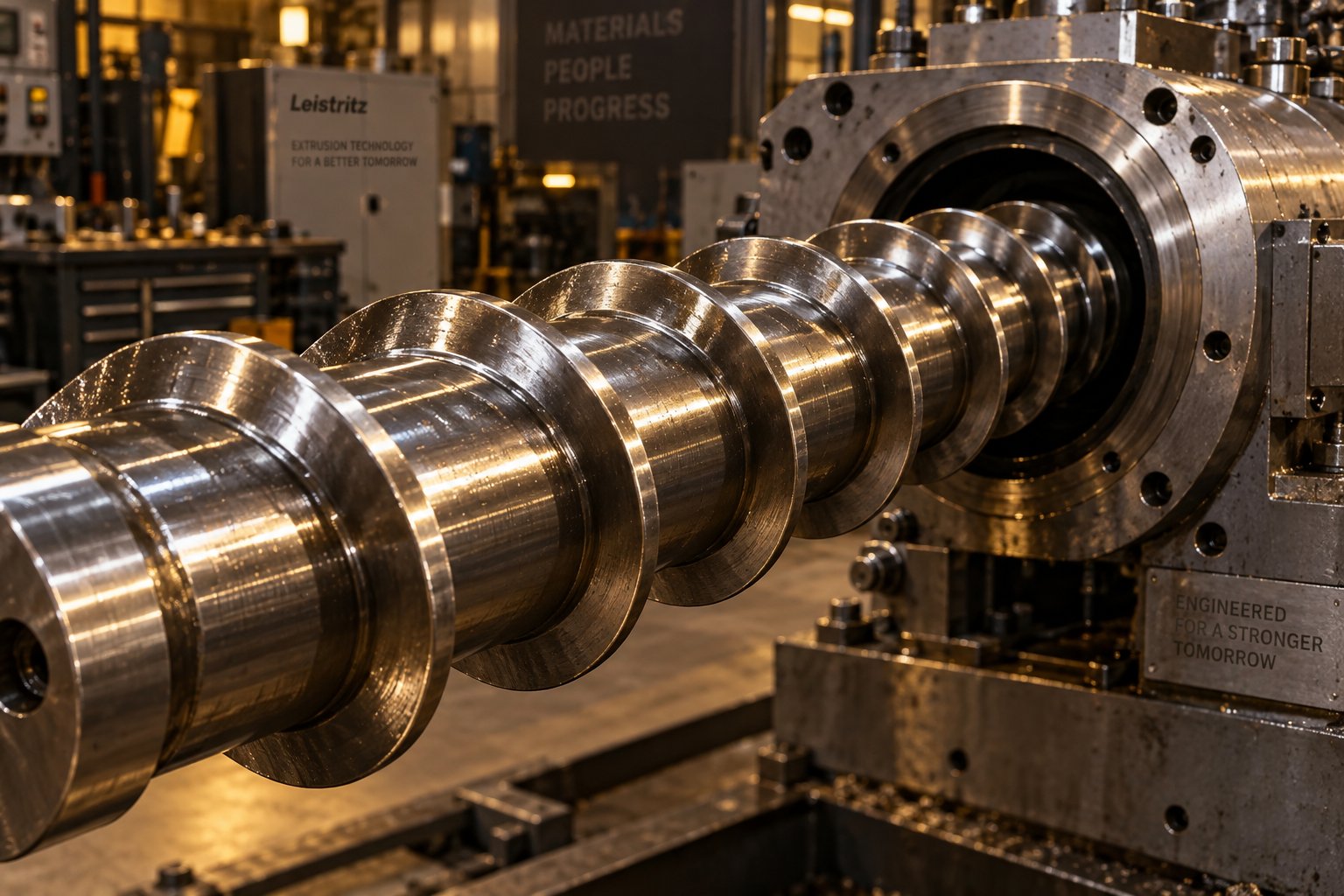
An extruder screw is the helical, rotating shaft housed inside the barrel of a screw extruder. Its job spans four critical functions: conveying raw PE pellets from the hopper, compressing them under increasing pressure, melting the polymer through a combination of shear and conducted heat, and homogenizing the resulting melt into a uniform stream ready for the die. Every extrusion screw is defined by its flight geometry, channel depths, compression ratio, and length-to-diameter ratio — parameters that must be tuned to the specific polymer it processes.
An extruder screw for PE is a precision-engineered rotating component designed to convey, compress, melt, and homogenize polyethylene resin inside the extruder barrel, with geometry optimized for PE's crystalline structure, melt elasticity, and shear sensitivity.
Why PE Requires a Purpose-Built Screw Design
Polyethylene is not a single material — it is a family of resins with wildly different melting behaviors. HDPE, for instance, has a sharp crystalline melting point that demands careful, gradual energy input. Push it too fast and you'll get premature melting, pressure spikes, and surging. LDPE and LLDPE, by contrast, soften over a broader temperature range, but their high melt elasticity makes them prone to melt fracture if shear rates climb too high in the metering zone.
Compare this to other commodity polymers. PVC behaves more like a rubber-like solid during processing and is typically run on double screw extruders with very low shear to avoid thermal decomposition. PE, on the other hand, requires roughly three times the specific energy input of PVC and processes as a true melt that crystallizes upon cooling — a fundamentally different thermodynamic challenge. PP sits closer to PE but tolerates a wider processing window and exhibits lower melt elasticity, meaning a PP-optimized screw will often over-shear or under-compress PE.
These differences are not trivial. Running PE on a general-purpose or polymer-mismatched screw leads to unmelts, inconsistent output, thermal degradation, and surface defects that no downstream adjustment can fix. This article breaks down everything PE processors need to know — from screw geometry and zone-by-zone design to grade-specific matching, advanced barrier and mixing technologies, defect troubleshooting, wear management, and practical selection criteria.
The starting point for all of it? Understanding exactly how each PE grade's molecular structure dictates the screw geometry it needs to perform.
How PE Grade Properties Dictate Screw Geometry
Imagine ordering one pair of shoes for every sport you play — running, hiking, basketball. You would lose performance everywhere. The same logic applies to extruder screws. A single plastic extruder screw geometry cannot serve every polyethylene grade equally, because each PE variant melts, flows, and conveys differently. Grade-specific screw design is the difference between an extrusion line that hums and one that fights you at every turn.
Screw Design Differences for HDPE vs LDPE vs LLDPE
HDPE's highly crystalline molecular structure means it behaves almost like a solid right up to its sharp melting point of roughly 266°F (130°C). It does not gradually soften — it resists, then melts abruptly. This characteristic demands a screw with a more gradual compression zone and deeper feed channels. Why? If the transition zone compresses too aggressively, the solid bed in the channel breaks apart prematurely. Fragments of unmelted HDPE then ride through the metering section and exit the die as visible defects. Research on PE extrusion performance has demonstrated that when the solids conveying rate exceeds the screw's melting capacity — a risk amplified by overly deep feed channels or high compression ratios — solid polymer fragments appear in the extrudate, creating quality failures in pipe, film, and sheet products.
LDPE, with its branched molecular architecture, presents a friendlier melting profile. It softens over a broader temperature range and exhibits the highest melting flux among common polyethylenes at equivalent processing conditions. This means extruder screws designed for LDPE can tolerate a shorter transition section and faster compression without triggering the same solid bed breakup issues that plague HDPE. You'll notice, though, that LDPE's high melt elasticity introduces its own challenge: excessive shear in the metering zone can cause melt fracture and surface roughness.
LLDPE sits in a uniquely demanding position. Its linear molecular chains and narrow molecular weight distribution make it more shear-sensitive than LDPE, yet it does not melt as readily as its branched cousin. Experimental data from a study using five screws with compression ratios from 2.0 to 3.6 found that a compression ratio of approximately 2.8 was optimal for LLDPE pellets with a bulk density of 590 kg/m3. Screws with ratios of 2.0 and 2.4 could not develop adequate channel pressure, especially at low screw speeds, while ratios above 2.8 pushed more solids downstream than the melting capacity could handle at higher speeds. LLDPE also benefits from better mixing capability in the metering section — shallower channels paired with dispersive mixing elements help achieve the melt homogeneity that blown film and cast film applications demand.
Addressing MDPE and Recycled PE Grades
MDPE behaves as a middle ground between HDPE and LDPE in terms of crystallinity and melting behavior. Its moderate crystalline content allows slightly faster compression than HDPE without the same solid bed breakup risk, but it still requires deeper feed channels than a typical LDPE screw provides. For processors running MDPE pipe or geomembrane lines, a screw plastic extruder setup calibrated for HDPE will often work acceptably, though fine-tuning the compression ratio downward can improve melt consistency.
The more pressing challenge for today's PE processors is recycled polyethylene. Whether you're running rHDPE from post-consumer bottles or rLDPE from agricultural film, the feedstock introduces variability that virgin resin simply does not. Melt index can shift from lot to lot. Contaminants — paper residue, adhesive fragments, even small amounts of PVC from label backing — change the material's flow behavior and can chemically attack screw surfaces. Bulk density drops significantly when processing regrind or flake instead of virgin pellets, meaning the feed channel must be deeper to maintain adequate metering section pressure. As extrusion researchers have noted, if a moderate level of film recycle is added to pellets and the bulk density decreases substantially, a standard compression ratio may not keep the metering channel full and pressurized, requiring a redesigned screw with increased feed depth.
Multi-material recycled streams add another layer of complexity. Industry experts caution that when recycling coextruded PE products containing semi-crystalline barrier layers such as PET or nylon, those higher-melting polymers will not soften at normal PE processing temperatures. Barrier screws and tight-clearance mixers can trap these unmelted fragments, causing plugging and flow instability. Screw design for recycled PE must account for these realities from the outset — not as an afterthought.
| PE Grade | Recommended Compression Ratio Range | Feed Channel Depth Guidance | L/D Ratio Considerations | Primary Processing Challenges |
|---|---|---|---|---|
| HDPE | 2.5 - 3.5 (varies by application and MFI; consult resin supplier datasheets) | Deeper feed channels to accommodate high bulk density and sharp melting point | 24:1 to 30:1; longer L/D improves melt quality for pipe and blow molding | Sharp melting point causes solid bed breakup; pressure surges; high torque demand |
| LDPE | 2.5 - 4.0 (broader range tolerated due to gradual melting) | Moderate depth; lower bulk density than HDPE pellets | 24:1 typical; shorter transition section feasible due to high melting flux | High melt elasticity; melt fracture risk at elevated shear; tendency for die drool |
| LLDPE | ~2.8 optimal for pellet feedstock (per experimental data); 2.4 - 3.0 typical range | Moderate to deep; must keep metering zone full and pressurized | 24:1 to 30:1; mixing sections recommended to compensate for narrow MWD | Shear sensitivity; solid polymer fragments at high screw speeds; requires effective mixing |
| MDPE | 2.5 - 3.2 (intermediate between HDPE and LDPE) | Moderate depth; similar to HDPE but slightly reduced | 24:1 to 28:1; standard three-zone designs common | Moderate crystallinity; less forgiving than LDPE but less prone to surging than HDPE |
| Recycled PE (rHDPE, rLDPE) | Higher than virgin equivalent to compensate for lower bulk density of regrind/flake | Deeper feed channels required for lower and variable bulk density feedstock | 26:1 to 32:1; extended length aids melting of inconsistent feedstock | Variable melt index; contamination (PVC, paper, adhesives); inconsistent bulk density; potential for corrosive wear |
Note: Specific numerical values for compression ratio and channel depth should be verified against resin supplier datasheets and engineering references for each application, as they vary with extruder size, target throughput, and product geometry.
These grade-level differences in screw geometry raise a natural question: what exactly happens inside each section of the screw as PE moves from solid pellet to molten stream? The answer lies in a zone-by-zone breakdown of how feed, transition, and metering sections interact with polyethylene's unique melting mechanics.
Feed, Transition, and Metering Zones in PE Extrusion
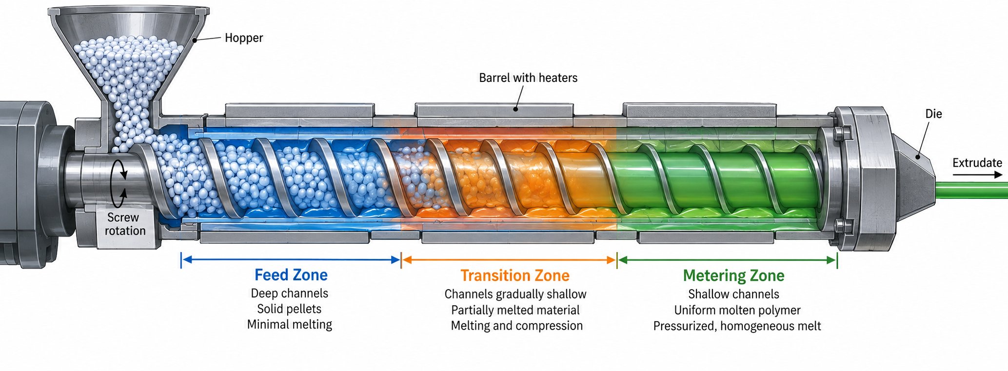
Every extruder screw for PE is really three machines in one. Each zone — feed, transition, and metering — performs a distinct job, and each one interacts with polyethylene differently than it would with PP, PVC, or any other commodity resin. When you understand what happens inside each section at a pellet-by-pellet level, the root causes behind surging, unmelts, and thermal degradation stop being mysteries and start becoming design problems with clear solutions.
Feed Zone Behavior With PE Pellets
The feed zone is where PE pellets first enter the extruder barrel and begin their journey toward the die. Sounds simple? It is anything but. Solids conveying in this zone depends on three physical properties of the pellets: bulk density, coefficient of friction, and pellet geometry. PE pellets — whether cylindrical, spherical, or lenticular — pack differently, and that packing determines how much material the screw can grab per revolution.
Bulk density matters because it defines how much mass fits into each helical channel. HDPE pellets typically have a higher bulk density than LDPE or LLDPE pellets, while recycled PE flake or regrind can drop bulk density by 30% or more. A feed zone designed for dense virgin pellets will starve when running low-density regrind, producing inconsistent output and pressure fluctuations downstream in the extruder process.
The coefficient of friction is equally important — but in a counterintuitive way. Efficient solids conveying requires high friction between the pellets and the barrel wall, combined with low friction between the pellets and the screw root. This friction differential is what propels the solid bed forward. If the screw surface is too "grabby," pellets rotate with the screw instead of advancing, and throughput collapses.
This is exactly where grooved feed barrel technology transforms PE processing. A grooved feed section features longitudinal or helical grooves machined into the extruder feed barrel wall, typically in the first 3 to 5 diameters of barrel length. These grooves mechanically lock the pellets against the barrel surface, dramatically increasing the effective friction coefficient at the barrel wall. The result is a solids conveying rate that is largely independent of the screw surface friction — a major advantage for PE, where pellet slip on smooth barrel walls can limit throughput. There is an important catch, though: grooved feed barrels generate much higher pressures in the feed section, which means the screw must have a lower compression ratio to avoid excessive pressure buildup and potential barrel or screw damage.
Feed throat cooling is another detail that PE processors cannot overlook. PE pellets begin softening at relatively low temperatures, and if heat migrates backward from the barrel into the feed throat, pellets can prematurely soften and bridge across the feed opening. Adequate water cooling of the feed throat and the first barrel zone keeps the extrusion barrel wall temperature below PE's softening point in this critical region, ensuring a steady and uninterrupted flow of solid pellets into the screw channels.
Transition Zone and PE Melting Mechanisms
The transition zone — also called the compression zone — is where the real work begins. Here, the screw channel depth gradually decreases, compressing the solid PE bed against the heated barrel wall and initiating melting. Imagine squeezing a sponge against a hot surface: the contact area increases, and the material at the interface melts first while the interior stays cold.
This analogy captures the core of Tadmor's melting model, which describes how a thin melt film forms at the solid-bed-barrel interface as the polymer contacts the hot barrel wall. As the screw rotates, the advancing flight scrapes this melt film off the barrel surface and collects it in a growing melt pool on one side of the channel. Meanwhile, the solid bed shrinks in width as melting continues. The mechanical energy dissipated through viscous shearing of this thin melt film is actually the primary melting mechanism — not the heat conducted from the barrel heaters.
Here is where PE processing gets tricky. As the solid bed narrows under compression, it eventually becomes so small that it can no longer withstand the internal channel pressure. At that point, the remaining unmelted pellets disperse — or essentially explode — into the surrounding melt pool. This phenomenon, known as solid bed breakup, is present in all conventional screw designs and is a major source of melt quality problems in PE extrusion.
Why is solid bed breakup so damaging? Because once the solid bed fragments, there is no longer a continuous melt film available for efficient viscous heat dissipation. The system becomes dependent on conductive heat transfer to finish melting the dispersed solid fragments — and plastic is an excellent insulator. Those unmelted particles ride through the remaining screw length with very little time or energy to finish melting. The result is unmelts in the final product, elevated and uneven melt temperatures, and in severe cases, visible defects in film, pipe, or sheet.
HDPE is particularly vulnerable to solid bed breakup because of its sharp crystalline melting point. The solid bed remains rigid and intact until very close to the melt temperature, then transitions abruptly. If the compression zone is designed too aggressively — too steep a channel depth reduction over too short a length — the solid bed fractures before the screw has enough length to complete melting. LLDPE faces a related but distinct problem: its higher shear sensitivity means that once solid bed breakup occurs, the unmelted fragments cannot be rescued by simply increasing barrel heat without risking degradation of the already-melted resin.
Metering Zone for PE Melt Homogeneity
By the time PE reaches the metering zone, it should ideally be a fully molten, thermally uniform stream. The metering section's job is to establish a consistent melt pressure and deliver a stable volumetric flow rate to the die. It is the section that determines whether your extrudate has uniform wall thickness, smooth surfaces, and predictable dimensions — or not.
Channel depth in the metering zone is the single most influential geometric parameter here. A shallower metering channel increases the shear rate experienced by the melt, which generates more viscous heat and raises melt temperature. A deeper channel reduces shear and lowers melt temperature but may sacrifice mixing quality. For PE — especially shear-sensitive LLDPE — this tradeoff is critical. Too much shear in the metering zone does not just raise temperature; it can trigger melt fracture, a surface instability that produces rough, uneven extrudate surfaces.
Research on melt flow behavior in single-screw extruders has shown that the velocity profile across the metering channel height is far from uniform — it varies significantly with the polymer's non-Newtonian rheology, the dimensionless flow rate, and the channel geometry. For PE, which exhibits strong shear-thinning behavior, the velocity profile flattens near the channel center where shear rates approach zero. This means viscosity increases sharply in the middle of the channel, creating a plug-like flow core that resists mixing. Proper metering zone design for PE must account for this rheological reality, using channel dimensions that keep shear rates within the optimal range for PE's viscosity curve.
Temperature uniformity across the melt stream at the metering zone exit is equally important. PE's sensitivity to both overheating and under-shearing means the metering zone must walk a narrow line — providing enough mechanical work to homogenize the melt without generating the excess viscous heating that leads to thermal degradation, discoloration, or reduced physical properties in the final product.
- Feed Zone: Conveys solid PE pellets forward using friction differential between the barrel wall and screw surface. For PE, pellet bulk density, coefficient of friction, and feed throat cooling are critical factors. Grooved feed barrels significantly boost solids conveying rates but require screws with reduced compression ratios.
- Transition (Compression) Zone: Compresses the solid bed and melts PE through viscous shear dissipation at the barrel wall interface. Solid bed breakup — the premature fragmentation of the unmelted solid bed — is the primary threat to PE melt quality in this zone, especially for HDPE and LLDPE.
- Metering Zone: Delivers a thermally uniform, fully molten PE stream at consistent pressure to the die. Channel depth governs the shear rate and melt temperature. PE's shear-thinning behavior and sensitivity to viscous overheating make metering zone geometry the final gatekeeper of output quality.
Each of these zones is defined by measurable screw parameters — L/D ratio, compression ratio, channel depth, pitch, and flight clearance. Knowing how to specify those numbers for PE, rather than relying on generic defaults, is what separates a screw that performs from one that merely rotates.
Essential Screw Parameters Every PE Processor Must Know
Specifying an extruder screw for PE is not a matter of picking a catalog number and hoping for the best. Every dimensional choice — from overall length to the depth of the last metering flight — shapes how the polymer melts, mixes, and exits the die. Yet many processors order replacement screws by repeating whatever dimensions came with the machine, never questioning whether those numbers actually suit the PE grade they are running today. That disconnect between screw geometry and resin behavior is where quality problems take root.
If you have ever reviewed an extruder drawing from an OEM, you have seen the maze of dimensions that define a screw. The challenge is knowing which ones matter most for polyethylene and how to think about them in relation to each other.
L/D Ratio and Compression Ratio for PE
The length-to-diameter ratio (L/D) describes the working length of the screw relative to its bore diameter. A 2.5-inch screw that is 60 inches long has an L/D of 24:1 — the most common ratio in single-screw extrusion. Some PE applications push to 30:1 or beyond, while a few older machines run as short as 20:1.
Why does PE typically benefit from a longer screw? Because more length provides more residence time for melting, more barrel surface area for heat transfer, and more channel length for mixing. PE's high specific energy requirement and its vulnerability to solid bed breakup both argue for additional screw length. A longer transition zone can apply compression more gradually, reducing the risk of premature solid bed fragmentation that plagues HDPE. A longer metering section allows shear-sensitive LLDPE melts to homogenize at lower screw speeds, cutting viscous overheating.
The extrusion screw compression ratio — the ratio of the feed channel volume to the metering channel volume — is the other headline parameter. In a constant-pitch screw, it simplifies to the ratio of feed channel depth to metering channel depth. Typical values for PE fall between roughly 2.5:1 and 4:1, though the optimal number depends heavily on the PE grade, pellet bulk density, and whether a grooved or smooth-bore feed section is used. As veteran extrusion engineer Allan Griff notes, compression ratio is a useful descriptor, but it is an indefinite number that cannot properly describe a screw unless at least one channel depth is also known. A 3:1 ratio with a 0.4-inch feed depth behaves very differently from a 3:1 ratio with a 0.25-inch feed depth — even though the ratio is identical.
For HDPE, a moderate compression ratio combined with a gradual transition avoids the abrupt pressure spikes that cause surging. LDPE tolerates higher ratios because its broad melting range absorbs faster compression without solid bed breakup. LLDPE, as discussed earlier, performs best near a 2.8:1 ratio for standard pellet feedstock. And grooved feed barrel systems — which generate their own high solids conveying pressure — demand screws with intentionally reduced compression ratios to prevent over-pressurization.
Channel Depth, Pitch, and Flight Geometry
Channel depth is arguably the most tangible design variable in screw extrusion because it directly controls shear rate, melt temperature, and output capacity. In the feed zone, deeper channels accommodate PE's relatively low bulk density — especially for LDPE pellets and recycled PE flake — ensuring that enough mass enters each screw revolution to keep the metering zone fully pressurized. In the metering zone, channel depth governs the shear rate applied to the melt. Shallow metering channels increase shear and viscous heating; deep channels reduce shear but can compromise mixing and pump efficiency.
The relationship between PE's molecular weight distribution (MWD), melt index (MI), and optimal channel depth is a nuance that most screw specifications overlook. A broad-MWD HDPE with a low melt index is highly viscous and shear-thins aggressively — it can tolerate shallower metering depths without overheating because the high-shear viscosity drops steeply. A narrow-MWD LLDPE with a similar MI, however, does not shear-thin as readily. The same metering depth would generate significantly more viscous heat, pushing melt temperature beyond acceptable limits. This is why melt index alone is never enough to specify a screw — you need to understand the MWD behind that number.
Pitch — the axial distance from one flight to the next — determines how far the polymer advances per screw revolution. Most PE screws use a square pitch, where the pitch equals the screw diameter. This makes it easy to estimate L/D simply by counting turns. Wider pitch increases throughput potential but reduces residence time and can limit melting capacity. Narrower pitch extends residence time, improving melt quality at the cost of reduced output rate.
Flight geometry rounds out the picture. Flight width — the thickness of the helical land — is typically about 10% of the barrel diameter. Wider flights waste effective screw length and generate excessive heat in the flight-to-barrel clearance zone, while narrower flights allow too much melt leakage back over the flight tips. The flight-to-barrel clearance on a new screw typically falls between 0.005 and 0.010 inches (0.125 to 0.25 mm), scaling with extruder size. Tighter clearances would increase manufacturing cost and generate excessive shear heat; looser clearances reduce pumping efficiency and allow back-leakage that hurts output consistency.
- L/D Ratio: Defines the working screw length relative to bore diameter. PE benefits from higher L/D (24:1 to 30:1+) for gradual compression and thorough melting, especially with HDPE and recycled PE grades.
- Compression Ratio: The feed-to-metering channel volume ratio, typically 2.5:1 to 4:1 for PE. Must be matched to PE grade, pellet bulk density, and feed section type (smooth vs. grooved bore).
- Feed Channel Depth: Deeper channels accommodate PE's lower bulk density and ensure adequate mass flow into the metering zone. Critical for recycled PE flake and regrind.
- Metering Channel Depth: Controls shear rate and melt temperature. Must be calibrated to the PE grade's MWD and shear-thinning behavior to avoid viscous overheating.
- Pitch: Axial distance between flights; square pitch (pitch = diameter) is standard for PE. Adjusting pitch trades throughput for residence time.
- Flight Width: Approximately 10% of barrel diameter. Balances effective channel length against leakage flow and shear heat generation at the flight tip.
- Flight Clearance: Typically 0.005 to 0.010 inches on new screws. Affects shear heating, pumping efficiency, and is a primary wear indicator over screw life.
Screw design for PE is always a balance of three competing demands: maximizing throughput, achieving uniform melt quality, and maintaining thermal consistency across the entire melt stream — optimizing one at the expense of the others is a recipe for chronic processing problems.
These parameters do not exist in isolation. They interact with each other and with the extruder's barrel, heaters, and die in complex ways. A perfectly specified metering depth means little if the screw lacks the mixing capability to break up gels or homogenize color concentrates. That is where advanced screw technologies — barrier flights, mixing elements, and grooved feed systems — take over where basic three-zone geometry leaves off.
Advanced Screw Designs That Elevate PE Processing
A standard three-zone metering screw can process polyethylene — the same way a dull knife can cut bread. It gets the job done, but the results are ragged. The parameters discussed so far — L/D ratio, compression ratio, channel depth — define the foundation of screw geometry, yet they cannot overcome the fundamental limitation of a conventional single-flight design: it has no mechanism to prevent solid bed breakup, no dedicated mixing capability, and no way to decouple solids conveying from screw friction. Modern screw technologies address each of these shortcomings directly, and for PE processors chasing tighter tolerances, higher throughput, or recycled-content targets, they are not luxuries — they are necessities.
Barrier Screws and Their Advantage for PE
Picture a conventional screw channel in the transition zone. A solid bed hugs one side while a growing melt pool collects on the other. Nothing physically separates them. As the solid bed thins, it fragments and disperses into the melt — the solid bed breakup phenomenon that generates unmelts, temperature spikes, and surging.
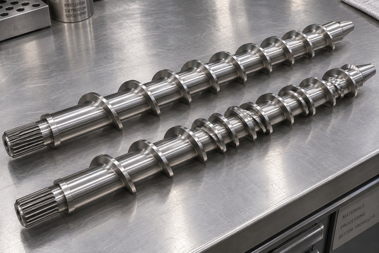
A barrier screw solves this problem with elegant simplicity: it introduces a secondary flight — called the barrier flight — that runs parallel to the main flight through the transition zone. This barrier flight has a slightly smaller diameter than the primary flight, creating a narrow clearance between its tip and the extruder barrel wall. Molten PE can flow over this clearance into a dedicated melt channel on the other side, while solid pellets and compacted resin remain trapped in the solids channel. The solid bed never gets a chance to break apart and contaminate the melt pool because the two phases are physically segregated throughout the melting process.
Why is this especially valuable for PE? Recall that HDPE's sharp crystalline melting point makes its solid bed rigid and prone to abrupt fracture. A barrier screw keeps that solid bed contained and forces it to melt progressively from the barrel-wall interface inward, regardless of how stubbornly it resists softening. LLDPE benefits equally — its shear sensitivity means that unmelted fragments reaching the metering zone cannot simply be "cooked out" with more barrel heat without degrading the surrounding melt. The barrier design ensures those fragments never arrive in the first place.
The performance difference is measurable. Barrier screws typically deliver lower melt temperature variation, fewer gels, and more consistent output pressure compared to conventional metering screws running the same PE grade at the same throughput. For PE pipe, blown film, and blow molding applications where melt homogeneity directly determines product quality, the barrier screw has become essentially standard practice on modern extruder screw barrel assemblies.
Mixing Sections and Grooved Feed Technology
Even a well-designed barrier screw does not inherently mix the melt. It separates solids from liquid — a melting improvement, not a mixing one. When your PE application involves color concentrates, mineral fillers like calcium carbonate or talc, UV stabilizers, or recycled PE with variable melt properties, dedicated mixing elements become essential.
Mixing elements fall into two functional categories, and understanding the distinction matters for specifying the right extruder screw barrel configuration:
- Dispersive mixers apply high shear stress to break apart agglomerates, gels, or poorly melted particles. The Maddock (or LeRoy) mixer is the most common dispersive element in single-screw PE extrusion. It consists of a series of parallel fluted channels separated by barrier lands. Melt is forced over these lands through a tight clearance, subjecting every fluid element to intense shear. As extrusion technology specialists explain, dispersive mixing works by applying internal stress — shear and elongational forces — to break down clusters of solid particles or liquid droplets that would otherwise persist in the matrix resin.
- Distributive mixers focus on spatial rearrangement rather than force. They split, reorient, and recombine melt streams to achieve compositional uniformity without generating excessive shear heat. Pineapple mixers, pin mixers, and blister rings all serve this function. Distributive mixing progresses through repeated division and recombination of flow streams — a process that expands the interfaces between components and produces a more uniform blend.
For PE applications, the choice between dispersive and distributive mixing — or a combination of both — depends on the task. Color concentrate dispersion in HDPE pipe typically requires strong dispersive action to break apart pigment agglomerates. Filled PE compounds with glass fiber demand careful distributive mixing that spreads fibers evenly without excessive breakage. Recycled PE with variable melt index benefits from both: dispersive elements eliminate gels and unmelts, while distributive elements homogenize the inconsistent melt viscosity across the channel.
Grooved feed barrel technology, introduced briefly in the feed zone discussion, deserves a deeper look here because it fundamentally changes how the entire extruder screw barrel system operates. In a smooth-bore extruder, solids conveying depends on the friction differential between the barrel wall and the screw root. This makes throughput sensitive to pellet surface characteristics, temperature, and screw speed — variables that shift unpredictably with PE grade changes.
A grooved feed section eliminates this dependency. The machined grooves — typically 6 to 10 longitudinal channels in the first 3 to 5 diameters of the extruder barrel — mechanically lock PE pellets against the barrel wall. Solids conveying becomes a positive-displacement process driven by barrel geometry rather than friction. Throughput increases dramatically, often by 20% to 40% for PE compared to a smooth bore of the same diameter. Pressure in the feed section climbs correspondingly, which is why grooved feed systems demand specially designed screws with reduced compression ratios — typically in the range of 1.2:1 to 1.8:1, far lower than the 2.5:1 to 4:1 range used in smooth-bore PE processing.
This is not a minor adjustment. Installing a grooved feed barrel on an extruder and leaving the original screw in place is a recipe for excessive barrel pressure, screw deflection, and potential mechanical failure. The screw and barrel must be designed as a matched system. European PE pipe and film producers have widely adopted grooved feed technology for HDPE and LLDPE processing, but its success depends entirely on the extruder screw barrel combination being engineered as a unit.
Even small-scale extrusion setups face similar design tradeoffs. A filabot ex6 filament extruder, for instance, uses a compact single-screw design to produce 3D printing filament from PE and other polymers — and even at that scale, screw geometry, mixing capability, and feed consistency determine whether the filament meets diameter tolerances or produces constant quality problems.
Single-Screw vs Twin-Screw Configurations for PE
Most PE extrusion happens on single-screw machines. Pipe, blown film, cast film, sheet, wire coating, blow molding — all of these are dominated by single-screw extruders because they offer the combination of high output, process stability, and cost efficiency that PE converting demands. A well-designed single-screw extruder with the right barrier screw and mixing elements handles virgin HDPE, LDPE, and LLDPE with excellent melt quality at throughputs that twin-screw machines of the same barrel diameter simply cannot match economically.
Twin-screw extruders carve out their niche in PE compounding, masterbatch production, and filled PE systems. When you need to incorporate 40% calcium carbonate into an HDPE matrix, or blend PE with 15% glass fiber, or produce color masterbatch with precise pigment loading, a twin-screw machine's superior mixing and dispersion capability justifies its higher capital cost. The intermeshing, co-rotating screws generate both high shear for dispersive mixing and complex flow fields for distributive blending — capabilities that a single-screw extruder can only approximate with add-on mixing sections.
Twin-screw extruders also excel at processing recycled PE where the feedstock is contaminated, moisture-laden, or composed of mixed polymer types. Their strong degassing performance allows moisture and volatile contaminants to be extracted through vacuum venting ports, and their higher tolerance for variable input materials keeps the process stable when lot-to-lot consistency is poor. For PE recycling operations aiming at upcycled pellet quality, a two-stage system — single-screw for pre-melting and filtration, twin-screw for degassing and compounding — represents the current best practice.
| Comparison Factor | Single-Screw Extruder for PE | Twin-Screw Extruder for PE |
|---|---|---|
| Dominant PE Applications | Pipe, blown film, cast film, sheet, blow molding, wire coating | Compounding, masterbatch, filled PE, PE recycling and upcycling |
| Mixing Capability | Moderate — enhanced with barrier screws and dedicated mixing elements (Maddock, pineapple, blister ring) | Excellent — inherent dispersive and distributive mixing from intermeshing screw geometry |
| Degassing Performance | Limited — single vent port possible but constrained by screw design | Strong — multiple vacuum vent ports supported; ideal for moisture and volatile removal |
| Throughput per Dollar | High — lower capital cost delivers competitive output rates for PE converting | Lower — higher initial investment; justified by processing capability for complex formulations |
| Feedstock Tolerance | Best with clean, consistent PE pellets; requires screw modification for recycled feedstock | Handles contaminated, blended, and variable PE streams with greater process stability |
| Initial Capital Cost | Lower | 2 to 3 times higher due to gearbox complexity, modular screw elements, and control systems |
| Maintenance Complexity | Simpler — single screw and barrel replacement straightforward | More complex — modular screw elements and tight intermeshing tolerances require specialized service |
| Process Flexibility | Limited — screw must be changed or replaced for significantly different PE grades or applications | High — modular screw configurations can be rearranged for different PE formulations |
The choice between single-screw and twin-screw is rarely ambiguous for PE. If you are converting PE resin into a finished product — pipe, film, sheet, containers — a single-screw extruder with a properly designed screw and barrel remains the workhorse. If you are modifying PE resin itself — compounding, filling, blending, or recycling — a twin-screw extruder delivers the mixing intensity and process control that single-screw machines cannot replicate without significant compromise.
Regardless of which configuration sits on your production floor, neither one is immune to a different kind of failure: when the PE extrudate comes out looking wrong, and the screw geometry is correct, the problem often traces back to subtle interactions between screw design and specific PE defect mechanisms. Gels, melt fracture, sharkskin, surging — each has a screw-related root cause that most troubleshooting guides overlook.
Troubleshooting PE Extrusion Defects Linked to Screw Design
Your extruder is running. The barrel temperatures look right, the hopper is full, and the screw speed matches your process sheet. Yet the film has gels, the pipe surface looks like reptile skin, and the output rate drifts up and down every few minutes. You call the resin supplier. They test a retained sample and report it meets spec. So where does the problem live? More often than not, it lives inside the barrel — in the geometry, condition, or mismatch of the screw itself.
PE extrusion defects are rarely random. Each one traces back to a specific physical cause, and many of those causes originate in how the screw handles the polymer at each stage of the extruder process. Connecting the defect you see at the die to the screw zone responsible for it is the fastest path to a permanent fix.
Gels, Melt Fracture, and Sharkskin in PE Extrusion
Gels are the bane of PE film processors. They appear as tiny, translucent or opaque specks embedded in the film web, and they compromise both appearance and mechanical integrity. While some gels originate in the resin itself — crosslinked particles formed during polymerization — a surprising number are created inside the extruder. The culprit? Excessive residence time in dead spots within the screw channels.
Every screw design has regions where melt velocity drops to near zero: corners at the flight-root intersection, stagnant pockets behind mixing elements, or areas where a worn flight allows melt to circulate without advancing. PE that lingers in these dead zones continues absorbing thermal energy. Over time, it crosslinks or degrades into a gel particle that eventually dislodges and exits through the die. A screw with poorly designed mixing sections, abrupt channel depth transitions, or excessive flight-to-barrel clearance from wear creates more of these dead spots — and more gels.
Melt fracture is a different beast entirely. It manifests as a grossly distorted, wavy, or rough surface on the extrudate and occurs when the shear stress on the melt exceeds a critical threshold. While die geometry plays a role, the screw's metering zone bears significant responsibility. A metering channel that is too shallow for the PE grade being processed drives shear rates above the melt fracture threshold, causing the flow to become unstable before the polymer even reaches the die. LLDPE and HDPE are particularly prone because their molecular structures resist flow alignment under high stress. As melt fracture researchers have documented, the phenomenon involves stick-slip behavior where the melt alternately adheres to and slips along the metal surface, creating cyclical pressure variations that propagate into visible surface distortion.
Sharkskin — fine, regularly spaced ridges on the extrudate surface — is a milder cousin of melt fracture. It originates primarily at the die exit, where the melt surface stretches and tears as it accelerates from the no-slip wall condition to free-surface flow. But here is the connection most troubleshooting guides miss: a poorly mixed, thermally non-uniform melt arriving at the die amplifies sharkskin severity. When the screw delivers melt with temperature gradients across its cross-section — hotter near the barrel wall, cooler at the core — different regions of the melt have different viscosities and different critical stress thresholds. The result is uneven die-exit stretching and worse sharkskin than the same resin would produce with a well-homogenized melt. Better mixing capability in the screw — distributive elements that eliminate thermal gradients — can measurably reduce sharkskin without changing die geometry or adding processing aids.
Output Surging and Unmelts Traced to Screw Design
Few problems frustrate PE processors more than output surging — the rhythmic rise and fall of extruder pressure, throughput, and product dimensions. You'll see it on the pressure gauge as a slow oscillation, often cycling every 20 to 60 seconds, and it translates directly into gauge variation in film, wall thickness fluctuation in pipe, and weight inconsistency in blow-molded containers.
The most common screw-related cause of surging in PE extrusion is solid bed breakup in the transition zone. As described in earlier sections, when the solid bed fragments prematurely, chunks of unmelted PE tumble through the metering section. These chunks temporarily restrict flow, causing extruder pressure to spike, then release, causing pressure to drop. The cycle repeats as each new slug of solid material breaks free. Barrier screws address this directly by physically separating the solid bed from the melt pool, preventing the fragmentation that initiates the surge cycle.
Surging can also originate in the feed zone. Mark Spalding of Dow, one of the foremost authorities on single-screw extrusion, has demonstrated that the most common root cause for flow surging in smooth-bore extruders is improper temperatures in the solids conveying section. If the screw root runs too hot — due to inadequate internal screw cooling or insufficient cooling-hole depth — pellets soften prematurely and lose the friction differential needed for stable solids conveying. The specific rate oscillates wildly, and even a gear pump downstream can only mask, not fix, the problem. In one documented case, extending the screw cooling hole to the full length of the solids conveying section and installing a water pump to improve coolant flow permanently eliminated the surging. A hot or poorly cooled feed casing produces the same effect — if the extrusion controls show cycling screw speed or motor current, check whether the feed casing is warm to the touch before tearing apart the screw.
Unmelts — visible particles of solid PE in the extrudate — point to a different set of screw deficiencies. They signal that the screw's melting capacity is not keeping up with its conveying rate. Common causes include insufficient screw length (L/D too short for the PE grade), inadequate compression ratio that fails to press the solid bed firmly against the barrel wall, or worn flights that have opened the flight-to-barrel clearance beyond its design limit. When clearance increases, melt leaks backward over the flight tips instead of building pressure, and the effective shear in the thin melt film at the barrel wall drops. Less shear means less viscous dissipation, which means less melting energy — and unmelted particles ride through to the die.
Thermal Degradation and Screw Speed Optimization
PE's sensitivity to thermal history makes screw speed selection a balancing act. Higher screw speeds increase throughput and shear rate, but they also increase viscous heating — the frictional energy generated within the melt as it shears between the screw root, flight walls, and barrel surface. This viscous heating is not uniform. It concentrates in high-shear zones: the thin melt film in the transition zone, the flight tip clearance, and the shallow metering channel.
Research into polymer degradation under controlled shear conditions confirms that the combination of high shear rates and elevated temperature accelerates molecular chain breakage in thermoplastics. While the study focused on PP, the underlying mechanism — mechanical stress assisting thermal bond rupture — applies equally to PE. For PE specifically, excessive viscous heating causes chain scission that reduces molecular weight, lowering the melt viscosity and degrading the mechanical properties of the finished product. In severe cases, you'll see yellowing, odor, or brittleness in the extrudate.
The interplay between screw design and barrel temperature settings determines whether viscous heating helps or hurts. A screw with a shallow metering channel running at high speed generates more viscous heat than the barrel's cooling zones can extract. The melt temperature climbs above the set-point temperature — sometimes by 20 to 40 degrees Fahrenheit — a condition known as viscous overheating. Reducing barrel heater temperatures will not fix this, because the heat is being generated mechanically inside the melt, not conducted from outside. The only real solutions are screw design changes (deeper metering channel, optimized flight clearance), lower screw speed, or both.
Barrel heating and cooling zone configurations interact with screw geometry in ways that can either stabilize or destabilize PE melt quality. Tight extruder terminals — where heat zones transition abruptly from high to low setpoints — can create sharp temperature boundaries within the melt channel. PE's shear-thinning behavior means the melt viscosity in those cooler zones jumps suddenly, increasing local shear stress and potentially triggering the very melt fracture or surging that the temperature reduction was intended to prevent. Smooth, gradual thermal profiles that complement the screw's compression profile produce far better results.
- Gels: Likely screw-related causes include dead spots in channel geometry, poorly designed mixing sections, abrupt transitions creating stagnant melt zones, and excessive flight clearance from wear that allows melt to recirculate.
- Melt Fracture: Metering channel too shallow for the PE grade, generating excessive shear stress; poor melt homogeneity amplifying flow instability at the die entrance.
- Sharkskin: Thermally non-uniform melt from inadequate screw mixing capability; temperature gradients across the melt cross-section causing uneven die-exit stretching.
- Output Surging: Solid bed breakup in the transition zone (fix with barrier screw); hot screw root or feed casing in the solids conveying section; improper compression rate in the transition zone.
- Unmelts: Insufficient L/D ratio for the PE grade; compression ratio too low to maintain solid bed contact with barrel wall; worn flights reducing shear and melt film thickness.
- Thermal Degradation: Excessive screw speed generating viscous overheating; metering channel too shallow for the operating speed; barrel temperature profile mismatched to screw compression profile.
- Gauge Variation: Combination of surging and inconsistent melt temperature; often originates from transition zone instability and propagates through the metering section to the die.
Every defect on this list points back to the screw — its geometry, its condition, or its compatibility with the PE grade being processed. But there is a subtler failure mode that does not show up as a sudden defect. It creeps in over months and years as the screw wears, slowly widening clearances, rounding flight edges, and eroding channel surfaces until the screw that once ran perfectly begins producing the very problems listed above. Understanding how PE specifically accelerates different wear mechanisms — and recognizing the warning signs before quality collapses — is the next critical piece of the puzzle.
Screw Wear Mechanisms and Replacement Indicators for PE
A well-designed screw does not stay well-designed forever. From the very first revolution inside the extruder barrel, wear begins — metal surfaces grind, abrasive particles gouge, and corrosive byproducts eat away at flight surfaces and channel roots. The troubling part? Screw wear in PE processing is gradual enough that operators compensate without realizing it: a small bump in screw speed here, a temperature adjustment there. These incremental tweaks mask the degradation until the screw that once delivered flawless melt quality is now the root cause of the gels, surging, and thermal inconsistency covered in the previous section.
PE processing subjects extruder barrels and screws to three distinct wear mechanisms — abrasive, adhesive, and corrosive — and each one maps to specific PE applications and feedstock conditions. Understanding which mechanism is attacking your screw is the first step toward choosing the right metallurgy, coating, and replacement schedule.
Abrasive, Adhesive, and Corrosive Wear in PE Applications
Abrasive wear is the most common form of degradation in PE extrusion, and it accelerates dramatically when mineral fillers enter the picture. Calcium carbonate, talc, and glass fiber are routinely compounded into PE for stiffness, cost reduction, or barrier performance — and every one of these additives is harder than the steel surfaces they contact. As pellets are conveyed and compressed down the screw channel, filler particles act like microscopic sandpaper, removing material from flight lands, channel roots, and barrel walls. Industry experts note that some of the most aggressive fillers can reduce screw and barrel useful life by 50% or more. Larger particles with sharper corners inflict disproportionately more damage than smaller, rounder ones — a reality dictated by the end product's property requirements, not the processor's preference.
Root wear from abrasive fillers deserves special attention. Screw rebuilding specialists have observed that when processing glass-filled or mineral-filled PE, severe wear often appears in the feed section on the forwarding side of the flights, where filler-laden pellets are compressed with limited lubrication from unmelted polymer. Mixing sections and barrier flights also suffer because their function requires resin to flow over undercut flight geometry — as these surfaces erode, dispersion quality and melting efficiency decline progressively.
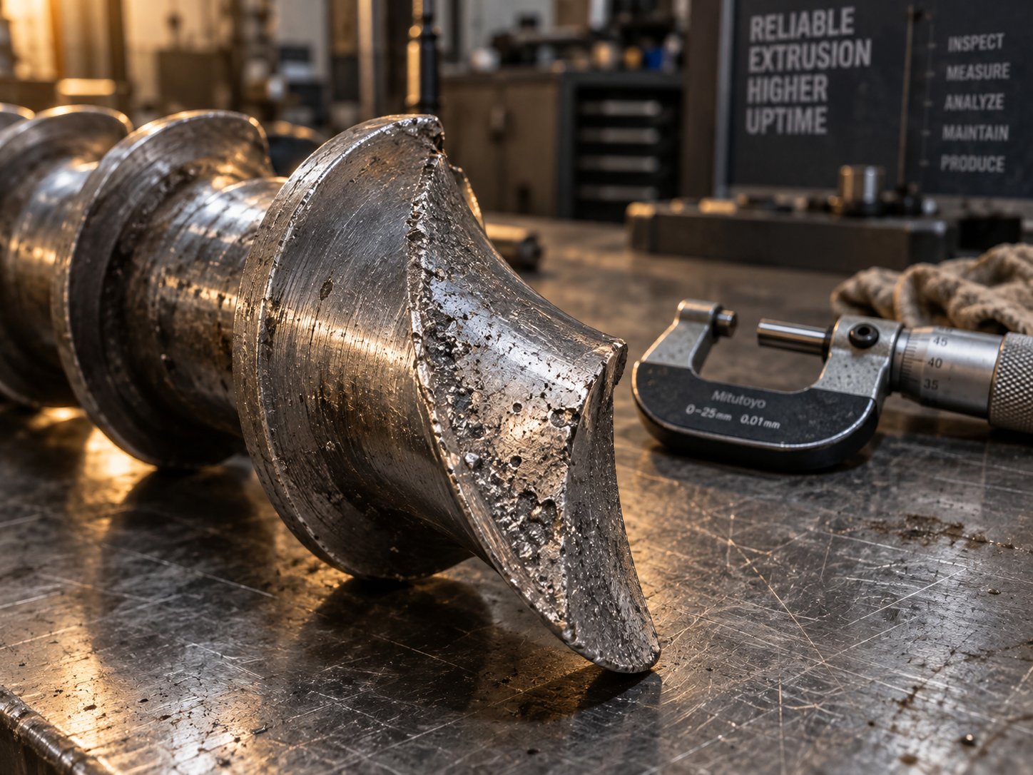
Adhesive wear follows a different mechanism entirely. It occurs when the screw flight lands and the interior barrel surface briefly contact each other under high pressure, momentarily weld together at microscopic asperities, and then fracture apart. Imagine two metal surfaces kissing under extreme load — each time they pull apart, tiny fragments of one surface transfer to the other. You'll recognize adhesive wear by a telltale burr or "rolling over" of the trailing edge of the flight land, or by scoring and galling visible on the barrel bore at the location where the screw damage occurred.
In PE processing, adhesive wear is most problematic with high-MFI (low-viscosity) grades. Why? A high-MFI PE produces a thinner melt film between the flight tip and the barrel wall. That thinner film provides less hydrodynamic separation — less cushion — between the two metal surfaces. Under the high pressures typical of the transition and metering zones, the probability of metal-to-metal contact increases. Processing high-MFI HDPE for injection molding feedstock or thin-wall packaging creates conditions where adhesive wear can progress rapidly, especially if the screw and barrel alloys are metallurgically incompatible.
Corrosive wear rounds out the trio, and it is the mechanism that recycled PE processors can least afford to ignore. Corrosion is the gradual chemical destruction of metal surfaces, and it damages the entire surface rather than just the high-contact points. In PE recycling, the corrosive agents come from unexpected sources: PVC fragments from labels or co-mingled waste streams release hydrochloric acid at PE processing temperatures. Paper residue and adhesive remnants generate organic acids during thermal decomposition. Moisture trapped in poorly dried regrind creates steam pockets that oxidize metal surfaces. Even acidic degradation byproducts from previously overheated PE can attack components with high iron content in their metallurgical matrix.
The insidious aspect of corrosive wear is that it weakens the metal surface, making it far more vulnerable to mechanical abrasion and adhesive damage. A corroded flight surface that would have resisted a mineral filler for thousands of hours crumbles under the same load in a fraction of the time. For extrusion barrels and screws processing post-consumer recycled PE, corrosion is rarely the only wear mechanism — it is the enabler that multiplies the damage from every other source.
Diagnosing Screw Wear and Knowing When to Replace
How do you know when your screw has crossed the line from "still working" to "costing you money"? The answer starts with measurement and ends with economics.
Measuring screw wear requires removing the screw from the barrel extruder, cleaning it thoroughly with brass tools and copper gauze — never steel wire brushes, which damage the surface — and allowing it to cool to room temperature. Davis-Standard's maintenance protocol recommends numbering each flight along the screw length, photographing each section alongside a tape measure for reference, and then using an OD bar micrometer to measure the outside diameter of every flight. These measurements are plotted against the original OEM dimensions to create a visual wear profile that reveals exactly where — and how much — material has been lost.
Channel depth should be checked with the same discipline. Root wear creates pockets and uneven surfaces that trap material and promote degradation, showing up as black specks in your extrudate. In severe cases, root erosion undercuts the flight sidewalls, leaving insufficient substrate to support the hardfacing alloy. The brittle hardface then chips away, contaminating the melt stream and potentially damaging downstream components like screen packs and dies.
Performance symptoms often reveal wear long before a micrometer confirms it. Watch for these signals:
- Reduced output at the same screw speed — as flight clearance increases, melt leaks backward over the flight tips instead of building forward pressure, reducing net throughput.
- Rising melt temperature — operators compensate for lost output by increasing screw speed, which generates more viscous heating. The melt temperature creeps above the process window.
- Poor melt homogeneity — wider flight clearance reduces the effective shear in the thin melt film, leaving the melt under-mixed and thermally uneven.
- Higher energy consumption — the drive motor works harder to maintain throughput as pumping efficiency drops. Energy cost per pound of PE processed rises steadily.
A common rule of thumb considers a flight clearance four times the original tolerance as the cutoff for screw replacement. But viscosity matters: a more viscous PE like low-MFI HDPE will suffer less output loss at a given clearance than a high-MFI PE under the same conditions. Rules of thumb are starting points, not verdicts.
The real decision point is economic. There is a point of diminishing returns where the cumulative cost of higher energy consumption, increased scrap rates, slower cycles, and degraded product quality exceeds the cost of rebuilding or replacing the screw. Identifying that tipping point before you reach it — through baseline data collection, regular wear measurement, and tracking process adjustments over time — is what separates planned maintenance from crisis management. An experienced screw manufacturer can often rebuild a worn screw to like-new condition for a fraction of the cost of a new one, and quality rebuilds can be performed multiple times on the same screw body, extending its useful life across many years of PE production.
| Wear Type | Primary PE Applications Affected | Visible Symptoms | Recommended Screw Material or Coating Solutions |
|---|---|---|---|
| Abrasive Wear | Filled PE compounds (CaCO3, talc, glass fiber); PE with pigment concentrates; recycled PE with grit or contaminants | Reduced flight OD; root erosion on forwarding side of flights; thinning of barrier flight undercuts; progressive loss of mixing element sharpness | High-tungsten-carbide hardfacing alloys (e.g., Colmonoy 56 or equivalent) on flight lands; bimetallic extrusion barrels with centrifugally cast wear-resistant linings; tool steel or PM steel screw bodies for severe applications |
| Adhesive Wear | High-MFI HDPE and LLDPE; thin melt film conditions in metering zone; applications with high extruder pressure and tight clearances | Burring or rolling of trailing flight-land edges; scoring or galling on barrel bore at corresponding screw location; hardfacing material chipped or missing from flight tips | Matched screw and barrel alloy pairs with compatible hardness to minimize galling tendency; high-hardness flight hardfacing with adequate tungsten carbide content; ensure screw straightness and barrel alignment to prevent mechanical deflection |
| Corrosive Wear | Post-consumer recycled PE (rHDPE, rLDPE) containing PVC, paper, adhesives; PE with flame-retardant additives; moisture-contaminated feedstock | Uniform surface pitting across flights and root; generalized roughening of metal surfaces; accelerated mechanical wear in areas weakened by corrosion; discoloration of metal surfaces | Nickel-based alloy barrels and screw coatings with high corrosion resistance; stainless steel screw bodies or nickel-rich bimetallic linings; improved feedstock drying and pre-screening to reduce corrosive contaminant load |
Note: Specific alloy grades and hardness values should be sourced from metallurgical data published by screw and barrel manufacturers for each application. Alloy compatibility between screw hardfacing and barrel lining is critical — softer alloys paired with hard barrel linings increase galling risk.
Wear is inevitable, but its pace and severity are not. The right metallurgy, the right coatings, and the right maintenance schedule can extend screw life dramatically — but only if the screw was designed for PE in the first place. A screw originally cut for PP or PVC that gets repurposed for PE will wear differently, melt differently, and fail differently. Understanding exactly how PE screws differ from their PP and PVC counterparts is what prevents that costly mismatch from ever reaching your production floor.
PE Screws Compared to PP and PVC Screw Designs
Repurposing a screw across polymers is one of the most expensive shortcuts in extrusion. It rarely destroys the machine — it just quietly destroys your margins through higher scrap, slower throughput, and chronic quality complaints that never fully resolve. The previous section showed how wear degrades a screw that was originally correct for PE. Running PE on a screw that was never correct for it accelerates every one of those problems from day one.
PE Screws vs PP Screws
PP and PE are both polyolefins, so many processors assume their screws are interchangeable. They are not. PP has a broader processing window and lower melt elasticity than HDPE, which means a PP-optimized screw typically features a higher compression ratio and a shorter, steeper transition zone. That aggressive compression works fine for PP because its semi-crystalline structure softens more gradually and its melt absorbs shear energy without the same fracture risk.
Drop that same screw into an HDPE line and the steep transition zone overwhelms the solid bed. HDPE's sharp crystalline melting point means the solid bed resists softening until it cracks apart under the rapid compression — triggering the solid bed breakup, surging, and unmelt issues covered earlier. PP screws also tend to have less intensive mixing sections because PP's broader molecular weight distribution provides inherent melt homogeneity that LLDPE, with its narrow MWD, simply cannot achieve without dedicated dispersive or distributive elements.
PE Screws vs PVC Screws
If the PE-versus-PP mismatch is subtle, the PE-versus-PVC mismatch is dramatic. PVC is thermally fragile — it begins degrading at temperatures barely above its processing range, releasing hydrochloric acid that corrodes metal surfaces and contaminates the product. PVC screws are engineered to minimize every possible source of shear heat: very low compression ratios (often 1.5:1 to 2.0:1), shallow channels, and gentle transitions that keep the polymer below its decomposition threshold.
PE needs the opposite approach. Its crystalline structure demands substantial mechanical energy input to melt, and its higher thermal stability allows — and in fact requires — the elevated shear rates that would destroy PVC. Running PE on a PVC screw starves the resin of the energy it needs. The result is a partially melted, poorly homogenized extrudate full of unmelts and surface imperfections. Flip the scenario — run PVC on a PE screw — and the high compression ratio and deep channels generate enough shear heat to thermally decompose the PVC, producing corrosive gas, black specks, and a potentially hazardous processing environment. Even compact systems like a filabot filament extruder or a filabot ex2 filament extruder, designed for prototyping and small-batch work, rely on screw geometry matched to the target polymer. A screw profile calibrated for PE filament will overshear PVC, and a PVC-safe profile will under-process PE.
- Compression ratio: PE screws use moderate ratios (2.5:1 to 4:1) tuned to grade-specific melting behavior. PP screws run higher ratios with steeper transitions. PVC screws use the lowest ratios (1.5:1 to 2.0:1) to limit shear heating.
- Transition zone length: PE — especially HDPE — requires a long, gradual transition to prevent solid bed breakup. PP tolerates shorter transitions. PVC uses gentle, extended transitions for thermal safety rather than melting efficiency.
- Metering channel depth: PE metering depths are calibrated to the grade's shear sensitivity and MWD. PP screws often have shallower metering zones that would overshear LLDPE. PVC metering channels are deliberately shallow and wide to minimize residence time and heat generation.
- Mixing capability: PE screws — particularly for LLDPE, filled PE, and recycled PE — frequently incorporate barrier flights and dedicated dispersive or distributive mixing elements. PP screws may include basic mixing but at lower intensity. PVC screws rarely include high-shear mixing elements to avoid localized degradation.
- Metallurgy and coatings: PE screws processing filled or recycled grades need high-hardness hardfacing and corrosion-resistant alloys. PVC screws prioritize corrosion resistance above all else due to HCl exposure. PP screws face the least aggressive chemical environment among the three.
Polymer-specific screw design is not optional for quality PE processing — a screw borrowed from a PP or PVC line may physically fit the barrel, but it will never deliver the melt quality, throughput, or energy efficiency that PE demands.
These distinctions make one thing clear: selecting the right screw for PE is not a generic purchasing decision. It requires matching screw geometry, metallurgy, and mixing capability to the specific PE grade, application, and feedstock condition. Knowing how to build that specification — and where to source a screw that meets it — is the final step toward putting everything in this article into practice.
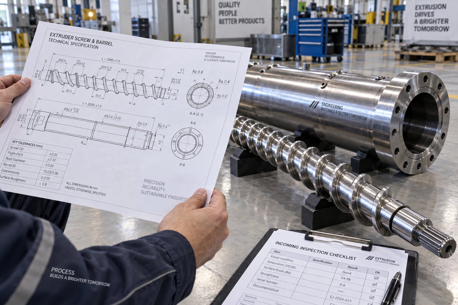
How to Select and Source the Right Screw and Barrel for PE
Every section of this article points to the same conclusion: PE extrusion performance lives or dies in the screw channel. Grade-specific geometry, barrier flight technology, wear-resistant metallurgy, proper mixing capability — none of it matters if the specification you hand to a manufacturer is incomplete or the supplier you choose lacks PE application experience. The gap between knowing what your screw should do and actually getting the right extruder screws and barrels delivered to your plant floor is where many processors stumble.
Think of this final section as the bridge between engineering knowledge and purchasing action. You have the technical foundation. Here is how to turn it into a specification sheet and a supplier relationship that delivers results.
Building Your PE Screw Specification Checklist
Before you contact any manufacturer for a quote, gather every piece of information that shapes screw design. A vague request — "I need a replacement screw for PE" — guarantees a generic response. A detailed specification gets you a screw engineered for your exact process. Here is what to have ready:
- PE grade and melt index (MFI): Specify whether you are running HDPE, LDPE, LLDPE, MDPE, or recycled PE. Include the resin supplier's grade name, the melt flow index, and the density. If you process recycled PE, note the approximate contamination level, bulk density of the feedstock (pellets, regrind, or flake), and whether any filler or additive is present.
- Target application: Pipe, blown film, cast film, sheet, pelletizing, recycling, blow molding, wire coating, or profile extrusion. Each application imposes different requirements for melt pressure, mixing intensity, and output stability — all of which influence screw geometry.
- Extruder make, model, and year: This tells the manufacturer the barrel bore diameter, drive capacity, and mechanical constraints they must work within. Include the gearbox torque rating if available.
- Current screw dimensions: Provide the existing screw's diameter, overall length, L/D ratio, flight count per zone, channel depths in the feed and metering sections, and compression ratio. If you have the original OEM drawing, send it. If not, detailed measurements and photographs — numbered flight-by-flight, as described in the wear diagnosis section — give a competent manufacturer enough to work from.
- Throughput requirements: State the target output rate in kg/h or lb/h, along with the screw speed range you plan to operate within. A screw optimized for 200 kg/h at 80 RPM will not perform identically at 350 kg/h and 120 RPM.
- Special requirements: Does your extruder use a grooved feed barrel? Do you need a vented screw for degassing moisture from recycled PE? Are barrier flights or specific mixing elements (Maddock, pineapple, blister ring) required? Will the screw need to handle color concentrate dispersion or mineral filler distribution? Each of these factors alters the screw design significantly.
- Known processing issues: If your current screw produces gels, surging, unmelts, or thermal degradation, document these problems. A skilled manufacturer uses this information to adjust the replacement screw design rather than simply duplicating the geometry that caused the issues.
- Barrel condition: A new screw installed inside a severely worn barrel will have excessive flight clearance from day one. Measure the barrel bore diameter at multiple points along its length. If wear exceeds the manufacturer's tolerance, replacing the barrel alongside the screw is the only path to restoring proper performance — installing one without the other wastes half the investment.
This checklist is not bureaucratic paperwork. It is the raw material your screw manufacturer needs to do their job properly. Skip any item and you introduce guesswork into a decision that affects every kilogram of PE your line produces.
Finding a Reliable Screw and Barrel Supplier for PE
A screw is only as good as the manufacturer behind it. The PE extrusion market is full of suppliers who can machine a helical flight to the right diameter — but far fewer who understand why HDPE pipe extrusion demands different channel geometry than LLDPE blown film, or why a recycled PE pelletizing line needs corrosion-resistant metallurgy that a virgin PE sheet line does not.
When evaluating potential extruder barrel alignment services suppliers and screw manufacturers, prioritize these capabilities:
- PE application expertise: Can the supplier demonstrate experience designing screws for your specific PE application — not just "plastics" in general? Ask for case studies or reference customers in pipe, film, sheet, recycling, or whichever process you run.
- Custom design capability: A supplier who only offers catalog screws cannot optimize for your PE grade, throughput target, and existing extruder constraints. Look for manufacturers who design screws based on your specification checklist, not from a generic size chart.
- Material and coating options: As the wear section of this article made clear, PE applications — especially filled and recycled PE — demand specific metallurgical solutions. Your supplier should offer nitrided steels, bimetallic barrels, tungsten carbide hardfacing, and corrosion-resistant alloys matched to your feedstock conditions.
- Breadth of application coverage: The best suppliers serve multiple PE end markets because cross-application experience sharpens their design instincts. NANHAIYA, for example, provides custom and replacement single screw barrels spanning pipe, film, sheet, pelletizing, recycling, and general-purpose plastic extrusion lines — a breadth that reflects deep familiarity with how different PE applications stress the screw-barrel system in different ways. That kind of range is a strong signal that a supplier understands PE processing holistically, not just one niche within it.
- Support for both new and replacement components: Your needs will shift over time. Today you may need a new screw optimized for a PE grade change. Next year, you may need a replacement barrel or a screw rebuild. Suppliers who support the full lifecycle — new builds, rebuilds, barrel relining, and wear assessment — become long-term partners rather than one-time vendors.
- Lead time and communication: Downtime while waiting for a screw is lost revenue. Ask about standard lead times, expedite options, and whether the supplier assigns a technical contact who understands your application and can answer process-related questions — not just order-tracking inquiries.
No single supplier is the right fit for every processor, and evaluating multiple options against your specification checklist is sound practice. That said, starting your search with manufacturers who already cover your PE application category — and who can point to a track record of custom screw and barrel work for polyethylene — eliminates the risk of handing your specification to a generalist who treats PE like every other polymer.
The right screw-and-barrel combination is the single most impactful investment a PE processor can make for output quality and efficiency — more consequential than resin selection, die design, or downstream equipment, because every one of those depends on the melt quality that only a properly engineered screw can deliver.
PE extrusion is unforgiving. The resin does not adapt to the screw — the screw must adapt to the resin. Armed with a complete specification checklist, a clear understanding of which screw parameters matter for your PE grade, and a supplier relationship built on application expertise rather than catalog convenience, you stop blaming the resin and start controlling the outcome.
Frequently Asked Questions About Extruder Screws for PE
1. What compression ratio is best for an extruder screw processing polyethylene?
The ideal compression ratio depends on the PE grade and feedstock form. LDPE tolerates a broad range of roughly 2.5:1 to 4.0:1 because of its gradual melting behavior. LLDPE performs best near 2.8:1 for standard pellet feedstock, while HDPE generally falls between 2.5:1 and 3.5:1 with a gradual transition zone to avoid solid bed breakup. Recycled PE flake or regrind typically needs a higher compression ratio than its virgin equivalent to compensate for lower bulk density. Grooved feed barrel systems require significantly reduced ratios — often 1.2:1 to 1.8:1 — because the barrel grooves independently generate high feed-zone pressure. Always cross-reference resin supplier datasheets and consult your screw manufacturer with your specific PE grade, melt index, and extruder configuration before finalizing a ratio.
2. Can I use the same extruder screw for HDPE, LDPE, and LLDPE?
Using a single screw across all PE grades is a common but costly compromise. HDPE's sharp crystalline melting point requires a long, gradual compression zone and deeper feed channels, whereas LDPE melts over a broader range and tolerates faster compression. LLDPE's narrow molecular weight distribution makes it highly shear-sensitive, demanding shallower metering channels paired with dedicated mixing elements. A universal screw may physically run each grade, but it will underperform on at least one — producing unmelts, gels, surface defects, or thermal degradation. Processors who frequently switch PE grades benefit most from having grade-optimized screws that can be swapped, or from selecting a barrier screw design with interchangeable mixing tips that partially bridge the gap between grades.
3. Why does my PE extruder produce output surging and how is it related to screw design?
Output surging in PE extrusion most commonly results from solid bed breakup in the screw's transition zone. When the solid PE bed fragments prematurely, chunks of unmelted resin intermittently block and release flow in the metering section, causing rhythmic pressure and throughput oscillations. Barrier screws address this by physically separating the solid bed from the melt pool with a secondary flight. Surging can also originate in the feed zone if the screw root or feed casing runs too hot, causing pellets to soften prematurely and lose the friction needed for stable conveying. Checking feed throat cooling, screw cooling-hole depth, and barrel zone 1 temperatures should be early diagnostic steps before assuming the screw geometry itself is at fault.
4. How do I know when my PE extruder screw needs replacement?
Key indicators include reduced output at normal screw speeds, rising melt temperatures that barrel adjustments cannot correct, increased gel counts or unmelts in the product, and higher energy consumption per kilogram of PE processed. Physically, you can diagnose wear by removing the screw, measuring every flight's outside diameter with an OD bar micrometer, and comparing the readings against original OEM specs. A widely cited benchmark is that flight clearance exceeding four times the original tolerance warrants replacement, though high-viscosity PE grades like low-MFI HDPE tolerate more clearance than high-MFI grades before output loss becomes significant. Tracking these metrics over time helps you identify the economic tipping point where screw rebuilding or replacement costs less than continuing to run a degraded component.
5. What is the difference between a barrier screw and a standard metering screw for PE extrusion?
A standard metering screw uses a single helical flight with three zones — feed, transition, and metering — but has no physical mechanism to separate the melting solid bed from the surrounding melt pool. This allows solid bed breakup, where unmelted PE fragments disperse into the melt and cause gels, unmelts, and surging. A barrier screw adds a secondary flight in the transition zone that creates separate channels for solids and melt. Molten PE flows over the barrier flight's reduced-diameter tip into the melt channel, while solids remain confined until fully melted. For PE — especially HDPE with its sharp melting point and LLDPE with its shear sensitivity — barrier screws deliver measurably lower melt temperature variation, fewer defects, and more stable output. Suppliers like NANHAIYA offer custom single screw barrel assemblies that can incorporate barrier flight technology matched to specific PE applications such as pipe, film, and recycling lines.
Written by
Nanhaiya Technical Team
Zhoushan Nanhaiya Plastic Machinery Co., Ltd.
The Nanhaiya technical team supports screw and barrel manufacturing projects through application review, technical communication, custom manufacturing coordination, and production and quality control.
Discuss Your Application
Related Articles
More insights on screw barrel technology and plastics processing.

What Nobody Tells You About Screw Barrel For Plastic Machine Design
Oct 10, 2026
Learn how screw barrel for plastic machine design affects melt quality, throughput, and wear life. Covers geometry, resin matching, troubleshooting, and sourcing.
Read Article
Single Screw Extruder for Sheet: Stop Guessing, Start Specifying
Oct 9, 2026
Learn how to specify a single screw extruder for sheet production. Covers screw geometry, resin-specific processing, troubleshooting, and maintenance best practices.
Read Article
PE Pipe Extruder Machine: What Datasheets Won't Tell You
Oct 9, 2026
Learn how a PE pipe extruder machine works, key specs explained, material grade selection, maintenance tips, and buyer guidance beyond the datasheet.
Read ArticleLooking for something else?
Search by material, symptom or product and jump straight to the relevant page.
These are navigation suggestions based on keyword matching — not a quotation, not a delivery commitment, and not a substitute for engineering review. Final specification is confirmed by our engineers against your drawings and processed material.
Need help with screw barrel selection?
Share your machine model, processed material and application. Our team can help with pricing and technical support.