

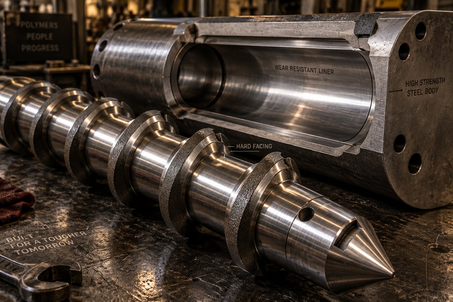
Why Extruder Screw Barrel Material Choices Make or Break Processing Performance
Every extruder screw barrel is, at its core, a consumable. The screw rotates inside the barrel bore under enormous pressure and temperature, gradually wearing down with every production hour. The metallurgy behind these two components — the specific alloys, heat treatments, and coatings applied to each — directly controls how long your equipment lasts, how consistent your output quality remains, and how much you ultimately spend per kilogram of processed resin. Get the material selection wrong, and you'll pay for it in premature replacements, climbing energy costs, and declining part quality for years.
Imagine running a filled nylon compound through a screw extruder built with the wrong steel grade. Within months, flight tips erode, the clearance between screw and barrel grows, and your specific output rate drops. To compensate, you increase screw speed — which raises discharge temperatures and degrades the polymer. Research from plastics processing experts at Plastics Technology demonstrates that even modest wear — a flight clearance increasing from 0.005 in. to 0.016 in. per side — can force rate reductions of 13% or more, directly cutting profitability and production capacity. That is the real cost of a poor material decision.
Why Material Selection Defines Extruder Performance
Here is a distinction most technical resources overlook: extruder screws and barrels serve fundamentally different mechanical roles, and they demand fundamentally different metallurgical properties. A screw rotates under cyclic bending and torsional stress. It needs a tough, fatigue-resistant core combined with a hard, wear-resistant surface. A barrel, on the other hand, is a static pressure vessel. It prioritizes bore surface hardness, chemical inertness, and dimensional stability. Treating both components as if they need the same material is one of the most common — and most expensive — mistakes in plastics processing.
Material selection is not about choosing the "hardest" option available. It is about matching material properties to specific polymers, fillers, and processing conditions. A harder screw in the wrong application can actually accelerate barrel wear and multiply your costs.
What This Resource Covers That Others Do Not
This article is built as a material-science-first guide for anyone responsible for specifying, purchasing, or maintaining extruder screws and barrels. You'll find a systematic breakdown of the three dominant wear mechanisms — abrasive, corrosive, and adhesive — along with how to diagnose which one is destroying your components. From there, you'll explore every major screw material grade, from basic carbon steels to powder metallurgy alloys, and every barrel liner technology, from nitrided bores to centrifugally cast bimetallic liners. Surface treatments, coating technologies, and the critical but often ignored principle of screw-barrel material pairing are all covered in detail. The goal is straightforward: give you the evidence and frameworks to make material decisions that protect your equipment investment and your bottom line.
The starting point for any of these decisions is understanding exactly how and why your components are wearing in the first place — and that begins with the three wear mechanisms that should shape every material choice you make.
Three Wear Mechanisms That Should Drive Every Material Decision
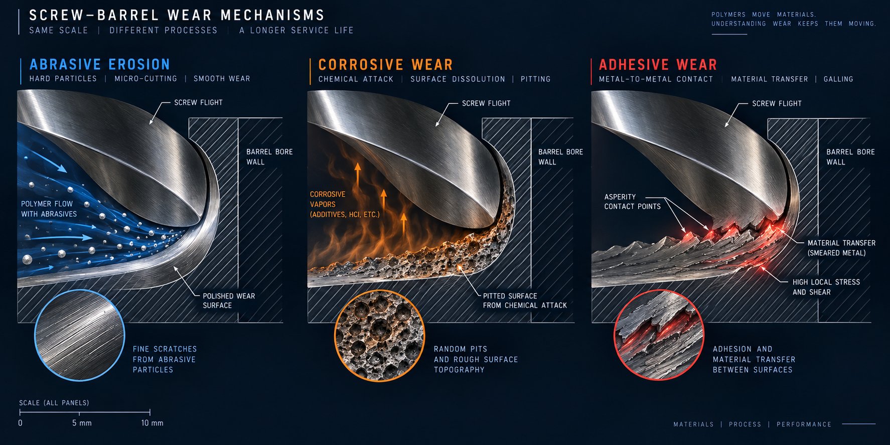
Before you compare steel grades, evaluate coatings, or request quotes on a new screw barrel set, you need to answer one question: what is actually destroying your current components? Wear inside an extruder barrel is not random. It follows predictable patterns driven by three distinct mechanisms — abrasive wear, corrosive wear, and adhesive wear. Each one attacks metal surfaces differently, leaves different forensic evidence on your components, and demands a different metallurgical response. Choosing the right extruder screw barrel material starts here, with an honest diagnosis of which mechanism dominates your specific process.
Most real-world extrusion applications involve some combination of all three. A glass-filled flame-retardant nylon, for example, subjects your extrusion screw barrel to simultaneous abrasive attack from glass fibers and corrosive attack from the flame-retardant chemistry. The key is identifying which mechanism is doing the most damage — because that dominant wear mode should dictate your material priorities.
Abrasive Wear from Fillers and Reinforcements
Abrasive wear is the most common and most visually obvious form of degradation in plastics processing equipment. It occurs when hard particles — glass fibers, mineral fillers like calcium carbonate and talc, titanium dioxide pigments, or even contaminants in recycled feedstock — physically scrape and gouge the metal surfaces of the screw flights and extruder barrel bore. Think of it as sandpaper running continuously against steel at high speeds and pressures.
The damage is mechanical and relentless. As pellets are transported down the screw channel and compressed against the barrel wall, the shearing action generated by screw rotation drags abrasive particles across both surfaces. Glass fibers are particularly aggressive. In twin-screw compounding operations, long glass fibers can entangle at the feed port, and as the screws rotate, these fibers shear into sharp fragments that intensify abrasion throughout the high-wear zones of the extruder. Mineral fillers like calcium carbonate and talc may seem softer than glass, but at high loading percentages — 40% or more — they accumulate enough cumulative contact force to wear through nitrided surfaces far faster than many processors expect.
The result is a gradual, measurable increase in clearance between screw flight tips and the barrel bore. That growing gap reduces shear rate, diminishes melting efficiency, and allows melt to leak backward over the flights, cutting throughput and spiking energy consumption.
How do you know abrasive wear is your dominant problem? Look for these telltale indicators:
- Uniform reduction in screw flight height across the metering section
- Smooth, polished wear surfaces on flight tips — not rough or pitted
- Barrel bore diameter increases that are evenly distributed along the barrel length, particularly in zones where fillers are fully dispersed
- Wear concentrated on the trailing edge of screw flight lands where solid material is compressed hardest against the barrel wall
- Screw root erosion in the rear of the channel, especially in the feed and transition zones where solid pellets and filler particles have not yet wetted into the melt
For applications dominated by abrasive wear, material selection should prioritize surface hardness and carbide content — both on the screw flight tips and within the barrel liner. Standard nitrided steels can handle unfilled or lightly filled resins, but once glass or mineral loadings climb above 20-30%, you'll need harder solutions like bimetallic barrel liners and hardfaced screw flights.
Corrosive Wear from Chemically Aggressive Polymers
Corrosive wear is subtler and often more dangerous than abrasion because it attacks the entire metal surface at the molecular level. Certain polymers release aggressive chemical by-products at processing temperatures — acids, halogens, or reactive gases — that dissolve the iron matrix of standard steel components from the inside out.
PVC is the most well-known offender. At elevated processing temperatures, PVC releases hydrochloric acid (HCl), which aggressively corrodes any component with a high iron content. Fluoropolymers like PTFE and FEP are even worse — they emit hydrofluoric acid (HF), one of the most destructive acids encountered in industrial processing. Acetal resins generate formic acid during thermal decomposition. Flame-retardant compounds, particularly those based on halogenated chemistries, add another layer of corrosive attack on top of whatever abrasive fillers they may contain.
The mechanism works like this: acid by-products chemically break down the protective oxide layer on the steel surface. Once that barrier is compromised, the underlying metal corrodes rapidly. This corrosion weakens the surface, making it far more vulnerable to mechanical wear. In effect, corrosion softens the steel so that even moderate mechanical forces — forces that would normally cause negligible damage — strip away material at an accelerated rate. Industry experts describe this as a synergistic effect where corrosion and mechanical wear amplify each other, reducing component life far more than either mechanism would alone.
Indicators that corrosive wear is dominating your process include:
- Surface pitting on the screw root diameter and barrel bore — small, irregular craters rather than smooth wear patterns
- A rough, etched appearance on metal surfaces that differs visually from the polished look of abrasive wear
- Discoloration or staining on component surfaces, particularly in venting zones where volatile acids concentrate
- Accelerated wear rates that seem disproportionate to the filler content — if your components are wearing faster than expected for the abrasive load, corrosion is likely a contributing factor
- Generalized thinning across broad areas of the barrel bore rather than localized spots
Combating corrosive wear requires a fundamentally different material strategy than fighting abrasion. Hardness alone will not save you. Instead, you need alloys with high nickel, chromium, and molybdenum content that resist chemical attack — materials like nickel-based bimetallic barrel liners and corrosion-resistant hardfacing alloys (such as Colmonoy 56 or Colmonoy 83) on screw surfaces.
Adhesive Wear and Metal-to-Metal Contact
Adhesive wear is the least intuitive of the three mechanisms, but it can cause the most sudden and catastrophic damage. It occurs when the screw flight tips physically contact the barrel bore — and at the microscopic level, the two metal surfaces momentarily weld together under extreme contact stress, then tear apart as the screw continues rotating. Each micro-weld-and-fracture cycle transfers material from one surface to the other, progressively roughening both components and creating a self-accelerating cycle of damage.
Under normal operating conditions, a thin film of polymer melt acts as a lubricating barrier between the screw and barrel. Adhesive wear becomes a problem when that barrier breaks down. Several conditions can trigger this breakdown: screw deflection under high melt pressure (the screw bends and physically touches the barrel wall), poor screw-to-barrel alignment, solids wedging in the transition zone that forces the screw off-center, or running the extruder at very low throughputs where insufficient melt coverage leaves metal surfaces exposed. As plastics processing specialist Jeff Kuhman at Glycon Corp. explains, when a screw designed for one polymer is run on a different resin with a different melting rate, the mismatch can cause solids to plug the channel and generate enough pressure to force the screw against the barrel wall — a condition known as solids wedging.
Signs that adhesive wear is active in your system:
- A visible burr or "rolling over" on the trailing edge of the screw flight land
- Scoring or galling marks on the barrel bore, typically localized to specific axial positions rather than distributed evenly
- Hardfacing material that appears cracked, delaminated, or missing from flight tips
- Smearing or material transfer visible on the screw flight surfaces — one metal deposited onto the other
- Damage that appears suddenly rather than gradually, often after a resin change or process modification
Preventing adhesive wear is as much about material compatibility as it is about hardness. The screw flight hardfacing and barrel liner alloy must be metallurgically compatible — certain combinations have a much greater tendency to gall than others. Alloys with lower tungsten carbide content, for example, may be easier to apply but are more prone to galling when paired with hard bimetallic barrel liners. Selecting materials that work together as a system, rather than specifying each component in isolation, is the only reliable defense against adhesive damage.
In practice, most processing operations face a blend of all three wear mechanisms at varying intensities. A processor running 30% glass-filled PVC, for instance, confronts severe abrasion from the glass, aggressive corrosion from hydrochloric acid, and potential adhesive damage if screw deflection brings flight tips into barrel contact. The material solution for that application looks nothing like the solution for unfilled polyethylene — and that difference is exactly why understanding these mechanisms matters before any material grade enters the conversation.
Screw Material Grades from Basic Steels to Powder Metallurgy
Diagnosing the dominant wear mechanism gives you a target. Selecting the right extruder screw material is how you hit it. But there is a critical engineering constraint that separates screw metallurgy from barrel metallurgy: a screw is not just a wear surface — it is a rotating structural member. Every revolution subjects the screw to cyclic bending loads, torsional stress, and fatigue. A material that is extremely hard on the surface but brittle at its core can crack catastrophically under these loads. That is why extruder screw material selection is always a balancing act between surface hardness for wear resistance and core toughness for mechanical survival.
The good news is that decades of field experience have produced a clear progression of material grades, each step up offering better performance for increasingly demanding applications. Understanding where your process falls on that spectrum — from unfilled commodity resins to heavily filled engineering compounds — determines exactly which grade delivers the best return on investment.
Nitriding Steels and Their Case Depth Limitations
The most widely used extruder screw materials fall into three broad categories of steel, escalating in cost and capability:
- Carbon steels (45# / AISI 1045): These are the entry-level option. With a carbon content around 0.42-0.50% and no significant alloying elements, 1045 steel offers decent machinability and adequate strength for screws processing unfilled polyethylene, polypropylene, and polystyrene. Surface hardness after heat treatment reaches roughly 22-28 HRC — enough for commodity resins with no abrasive fillers. The trade-off? Minimal wear resistance the moment any filler or reinforcement enters the melt stream.
- Alloy steels (40Cr / AISI 5140): Adding chromium improves hardenability and fatigue life. 40Cr steel — equivalent to DIN 41Cr4 (W. Nr. 1.7035) and roughly comparable to SAE 5140 — delivers 28-36 HRC after quenching and tempering and provides better wear resistance than plain carbon steel. Chromium refines carbide distribution, improving both surface hardness and fatigue performance. This grade works well for lightly filled resins and moderate-duty extrusion screws, but it still lacks the surface hardness needed for glass-fiber or mineral-filled compounds.
- Nitriding steels (38CrMoAlA / closest Western equivalents): This is the workhorse of the extrusion screw industry. 38CrMoAlA — a Chinese GB designation with no exact single AISI equivalent, though it shares design intent with specialized nitriding grades like Nitralloy 135M (AMS 6470) — is specifically formulated with aluminum, chromium, and molybdenum to respond exceptionally well to the nitriding process.
How does nitriding work? The process exposes the steel to a nitrogen-rich atmosphere at temperatures typically between 500-570 degrees Celsius. Nitrogen atoms diffuse into the steel surface and react with aluminum and chromium to form extremely hard nitride compounds — aluminum nitride and chromium nitride — creating a wear-resistant case on the outside while leaving the tough, ductile core untouched. Ion/plasma nitriding, as documented by Advanced Heat Treat Corp., can achieve surface hardness exceeding 65-70 HRC equivalent on grades like Nitralloy 135M and H-13 — impressive numbers that explain why nitrided extrusion screws dominate the market.
Here is the catch, though — and it is a significant one. The nitrided case is thin. Typical case depths range from 0.3 mm to 0.7 mm depending on process time and material grade. That hardened layer sits on top of a much softer core, usually around 30-35 HRC. Under abrasive conditions — glass fibers, mineral fillers, contaminated recycled feedstocks — that thin case gradually wears through. When it does, performance does not degrade gradually. It drops off a cliff. The soft core underneath has no meaningful abrasion resistance, and wear rates spike dramatically. Processors often describe this as a screw that "worked great for two years, then fell apart in two months." That sudden failure is not a mystery — it is the nitrided case reaching its end of life.
For unfilled or lightly filled commodity resins, nitrided 38CrMoAlA extruder screws are an excellent and cost-effective choice. For anything with significant abrasive loading, they are a temporary solution with an expiration date built into the physics of the case depth.
Tool Steels and Powder Metallurgy Grades for Demanding Applications
When nitriding steels run out of runway, the next tier of materials offers through-thickness wear resistance rather than relying on a thin surface layer. This is where tool steels and powder metallurgy (PM) grades enter the picture.
- Tool steels (D2 / SKD11 and H13): D2 (Chinese designation Cr12MoV, Japanese SKD11) is a high-carbon, high-chromium cold-work tool steel with a large volume of hard chromium carbides distributed throughout the matrix. After heat treatment, D2 reaches 58-62 HRC with excellent abrasion resistance. Its primary limitation is lower toughness — the very carbides that resist abrasion also create stress concentration points, making D2 more brittle under impact and cyclic fatigue. H13 (Chinese designation 4Cr5MoSiV1) is a hot-work tool steel that trades some of D2's hardness (typically 48-52 HRC after tempering) for significantly better toughness and thermal fatigue resistance. Ion nitrided H13 extruder screws can reach surface hardness exceeding 70 HRC equivalent while retaining a tough core — making H13 an outstanding choice for high-temperature extrusion applications where both wear and thermal cycling are concerns.
- Powder metallurgy grades (CPM 9V, CPM 10V): These represent the premium tier. Powder metallurgy production creates an extremely fine, uniform carbide distribution that conventional steelmaking cannot achieve. CPM 9V contains roughly 9% vanadium carbides and delivers exceptional abrasion resistance at 53-55 HRC while retaining far better toughness than conventional high-carbide tool steels. CPM 10V pushes vanadium content even higher for the most abrasive applications — heavily glass-filled nylons, mineral-loaded polypropylenes, and aggressive recycled feedstocks. The uniform microstructure also means PM grades respond extremely well to nitriding, achieving high surface hardness on top of an already wear-resistant substrate.
- Tungsten carbide hardfacing and Stellite overlays: Rather than upgrading the entire screw, some processors apply premium materials only where they are needed most — the flight tips. Tungsten carbide hardfacing, applied by plasma-transferred arc (PTA) or laser cladding, creates a flight tip surface with hardness exceeding 60 HRC and outstanding abrasion resistance. Stellite 6 and Stellite 12 cobalt-based overlays offer a different advantage: excellent resistance to both corrosion and adhesive wear, with good high-temperature hardness retention. However, as noted in industry research on surface welding for extruder screws, these overlay alloys have comparatively weaker adherence to the base screw material compared to through-hardened options — meaning application quality and process control are critical to long-term performance.
Cross-Referencing Chinese and Western Material Designations
If you source extruder screws globally — and most processors do — you will encounter Chinese GB grade designations alongside Western AISI, DIN, and JIS standards. Misidentifying a material grade during procurement can mean receiving a screw that looks correct on paper but performs dramatically differently in service. The table below bridges the most common designations so you can cross-reference specifications with confidence.
| Material Grade (Chinese / Western) | Typical Hardness After Treatment | Primary Strength | Primary Limitation | Best-Fit Application |
|---|---|---|---|---|
| 45# / AISI 1045 / C45 (DIN) | 22-28 HRC (Q+T) | Low cost, good machinability | Minimal wear resistance | Unfilled commodity resins (PE, PP, PS) |
| 40Cr / AISI 5140 / 41Cr4 (DIN 1.7035) | 28-36 HRC (Q+T) | Improved hardenability and fatigue life | Insufficient for abrasive compounds | Lightly filled resins, moderate-duty screws |
| 38CrMoAlA / Nitralloy 135M (AMS 6470) | 65-72 HRC surface (nitrided); 30-35 HRC core | Excellent surface hardness via nitriding | Thin case depth (0.3-0.7 mm); sharp performance drop when worn through | Unfilled to moderately filled resins; general-purpose extrusion |
| Cr12MoV / AISI D2 / SKD11 (JIS) | 58-62 HRC | High carbide volume for through-thickness abrasion resistance | Lower toughness; brittleness risk under impact | Abrasive filled compounds where fatigue loads are moderate |
| 4Cr5MoSiV1 / AISI H13 / SKD61 (JIS) | 48-52 HRC (tempered); 65-70+ HRC surface (nitrided) | Excellent toughness and thermal fatigue resistance | Lower base hardness than D2 without nitriding | High-temperature extrusion; demanding cyclic load applications |
| CPM 9V (Crucible Industries) | 53-55 HRC | Superior abrasion resistance with good toughness (PM microstructure) | Higher cost; limited global availability | Glass-filled nylons, mineral-loaded compounds |
| CPM 10V (Crucible Industries) | 58-62 HRC | Extreme abrasion resistance (highest vanadium carbide content) | Highest cost; reduced toughness vs. CPM 9V | Heavily glass-filled or mineral-filled engineering resins |
| Stellite 6 / Stellite 12 (overlay) | 39-48 HRC (Stellite 6); 44-49 HRC (Stellite 12) | Corrosion and adhesive wear resistance; retains hardness at high temperatures | Applied as overlay — adhesion quality depends on application process | Flight tip hardfacing for corrosive or high-temperature polymers |
| Tungsten carbide hardfacing (PTA/laser clad) | 60+ HRC | Outstanding abrasion resistance at flight tips | Brittle; not suitable as full-screw material; requires skilled application | Flight tip protection for extreme abrasion (high glass-fiber loadings) |
A few practical notes on reading this table. You'll notice that the progression is not simply "harder is better." CPM 9V at 53-55 HRC outperforms D2 at 58-62 HRC in many abrasive applications because its powder metallurgy microstructure distributes carbides more uniformly, preventing the crack-propagation paths that concentrate in conventionally cast tool steels. Similarly, H13 at a modest 48-52 HRC base hardness becomes a top-tier performer once nitrided — because the combination of a tough core and an extremely hard surface delivers exactly the balance that extruder screws need under cyclic mechanical loads.
The screw, however, is only half the equation. It operates inside a barrel whose bore surface faces its own distinct set of material challenges — challenges that demand a completely different metallurgical approach built around liner alloys, centrifugal casting technology, and chemical resistance rather than core toughness.
Barrel Materials and Liner Alloys for Every Processing Challenge
A screw needs to survive cyclic bending, torsional fatigue, and relentless mechanical stress — all while spinning at hundreds of RPM. A barrel does not. That fundamental difference reshapes the entire material selection conversation when you shift from the rotating component to the stationary one. Extruder barrels are pressure vessels. They sit still, absorb radial loads from melt pressure, and provide a dimensionally stable bore surface against which the screw does its work. The metallurgical priorities flip accordingly: instead of balancing surface hardness with core toughness, extrusion barrel materials must maximize bore surface hardness, chemical inertness, and long-term dimensional stability.
This distinction matters more than most processors realize. A material that excels as a screw alloy can be a poor barrel choice — and vice versa. Understanding what makes extruder barrels unique from a metallurgical standpoint is essential before evaluating the specific liner technologies that protect their bore surfaces.
Why Barrel Material Requirements Differ from Screw Requirements
Think about what a barrel actually experiences during operation. Polymer melt presses outward against the bore wall under pressures that can exceed 5,000 psi. Heater bands cycle temperature across the outer surface. Abrasive fillers grind against the inner bore as the screw conveys material forward. Corrosive by-products from PVC, fluoropolymers, or flame-retardant compounds attack exposed metal surfaces. Through all of this, the barrel must maintain its internal diameter within extremely tight tolerances — typically plus or minus 0.001 inches on finished bore diameter — because any deviation directly affects screw-to-barrel clearance, melt pressure stability, and output quality.
Since barrels are static, they do not face the cyclic fatigue loads that demand a tough, ductile core in screws. This frees barrel design to prioritize properties that would be problematic in a rotating component: extremely hard bore liners that might be too brittle for a screw, corrosion-resistant alloys that lack the fatigue life a screw demands, and thick carbide-loaded layers that would crack under the bending stress a screw experiences every revolution. In short, the barrel can be harder, more chemically resistant, and more metallurgically specialized at its bore surface than any screw material can afford to be.
The base barrel body itself — the thick-walled steel cylinder that provides structural integrity — is typically made from 38CrMoAlA (the same nitriding-grade steel used for screws) or from medium-carbon alloy steels like 40Cr or 42CrMo. When the barrel bore is nitrided directly, 38CrMoAlA provides surface hardness in the 65-70 HRC range — adequate for unfilled commodity resins like polyethylene, polypropylene, and polystyrene. The nitrided case depth on a barrel bore typically reaches 0.4-0.7 mm, the same range discussed for screws.
The problem? That thin nitrided layer faces the same cliff-edge failure risk on a barrel that it does on a screw. Once abrasive fillers or corrosive polymers wear through the case, the soft base metal underneath erodes rapidly. And here is where the consequences are far more severe: replacing a barrel costs significantly more than replacing a screw, involves much longer lead times, and often requires partial machine disassembly. A nitrided-only barrel that fails prematurely under abrasive or corrosive service is one of the most expensive material selection mistakes in plastics processing.
For anything beyond unfilled commodity resins, the industry has developed a better answer: bimetallic barrel technology.
Bimetallic Barrel Liners and the Centrifugal Casting Process
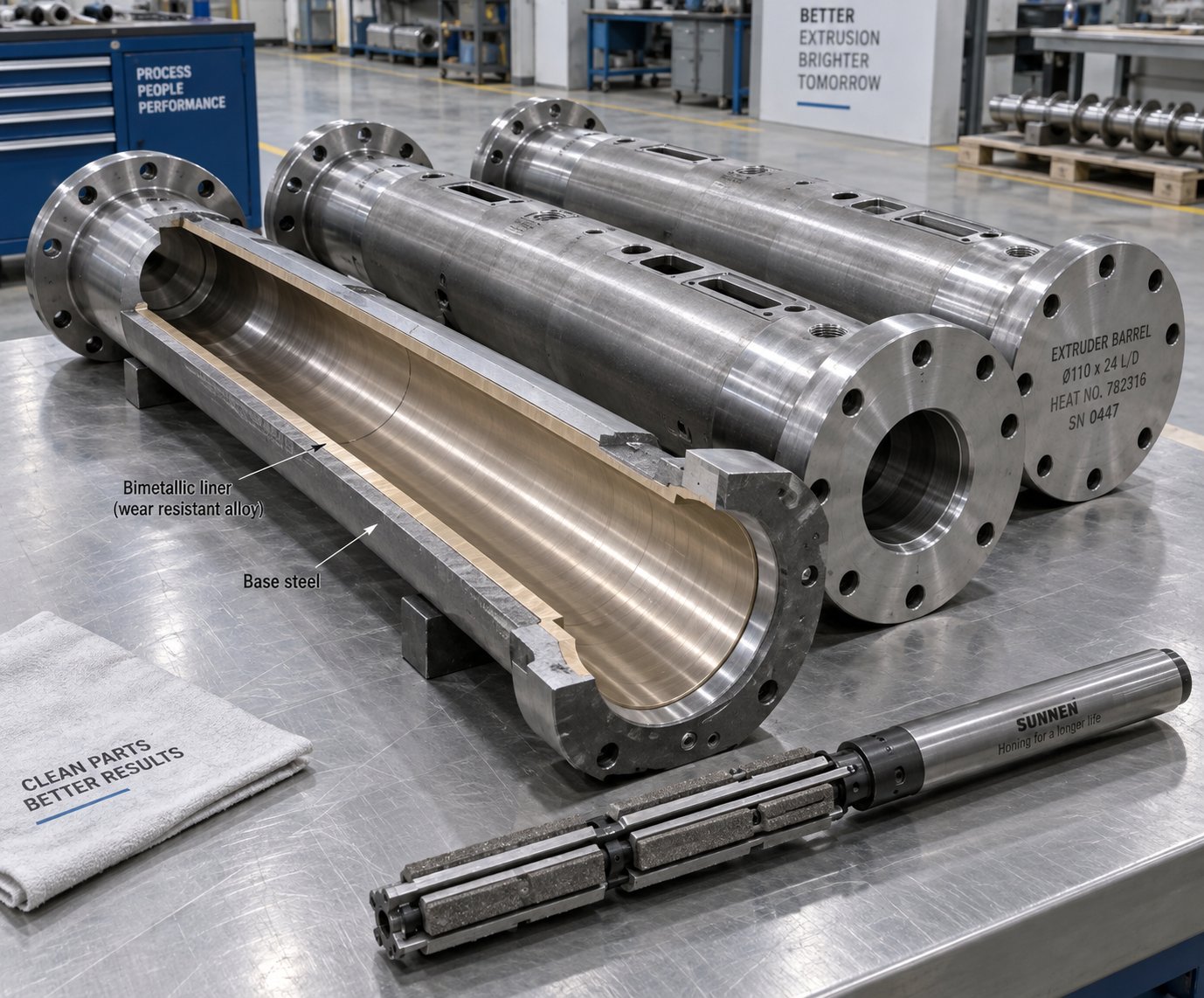
Bimetallic extrusion barrels solve the limitations of nitriding by placing a thick, wear-resistant alloy liner inside the barrel bore — essentially giving the barrel two distinct materials working together. The outer body provides structural strength. The inner liner provides the hardness, chemical resistance, or carbide content needed for the specific processing environment.
How are these liners applied? The dominant manufacturing method is centrifugal casting. The process begins with a solid bar of steel machined into a barrel cylinder. A carefully formulated wear-resistant alloy is heated in a furnace to temperatures above 2,000 degrees Fahrenheit until fully molten. The capped barrel cylinder is then placed onto high-speed casting rollers and spun at rapid rates of rotation. Centrifugal force drives the molten alloy uniformly against the inner bore wall, dispersing it evenly in thickness, hardness, and density. As the barrel cools, the alloy solidifies and metallurgically bonds to the base steel — not merely a mechanical attachment, but an atomic-level fusion between the liner and the barrel body.
After cooling, the bore is precision-honed to its final internal diameter specifications. The finished liner typically measures 0.050 to 0.060 inches thick — roughly 1.3 to 1.5 mm. Compare that to a nitrided case depth of 0.3-0.7 mm, and you can see the immediate advantage: a bimetallic liner offers two to four times the wear-resistant material depth, which translates directly into longer service life before the barrel bore exceeds wear tolerances.
The real power of bimetallic technology lies in the alloy flexibility. By changing the composition of the liner alloy, manufacturers can tailor barrels to resist abrasion, corrosion, or both — matching the barrel's wear resistance profile precisely to the polymers and fillers it will encounter. Three major alloy families cover the vast majority of applications:
- Iron-boron alloys: These are the general-purpose workhorses. Iron-boron liners (designated by trade names like W-666) contain hard iron boride particles dispersed in an iron matrix. They deliver excellent abrasion resistance at a moderate cost and handle most mineral-filled and moderately glass-filled compounds effectively. Hardness typically ranges from 55-65 HRC. Their limitation is corrosion resistance — the iron-rich matrix is vulnerable to chemical attack from PVC, fluoropolymers, and halogenated flame retardants.
- Nickel-based alloys: When corrosion is the dominant threat, nickel-rich liners take over. Alloys with high nickel content — comparable to Hastelloy C-276 equivalents — resist hydrochloric acid from PVC, hydrofluoric acid from fluoropolymers, and the acidic by-products of flame-retardant chemistries. Trade designations such as X-306 and W-555 represent formulations in this family. They sacrifice some abrasion resistance compared to iron-boron liners but provide the chemical inertness that corrosive polymers demand. For environments combining both corrosion and moderate abrasion — rigid PVC with calcium carbonate filler, for example — nickel-rich iron-boron hybrid alloys (like the X-102 designation) balance both properties.
- Tungsten-carbide-loaded alloys: For the most extreme abrasive applications — 40%+ glass-fiber-filled nylons, heavily mineral-loaded engineering compounds, or aggressive recycled feedstocks filled with metal contaminants — tungsten carbide liners represent the top tier. These alloys embed extremely hard tungsten carbide particles within a nickel or cobalt matrix. Spherical carbide formulations offer up to three times the wear resistance of tool steel, with the nickel matrix also providing superior corrosion resistance. Liner thickness in some carbide designs reaches 0.150 inches — roughly three times thicker than standard bimetallic liners — and eliminates weld lines that can cause premature splitting or chipping. Designations like X-800 represent tungsten-carbide-in-nickel formulations that address both extreme abrasion and corrosive conditions simultaneously.
Choosing among these alloy families comes back to the wear mechanism diagnosis covered earlier. If abrasion dominates and corrosion is negligible, iron-boron liners deliver excellent performance per dollar. If corrosion dominates, nickel-based liners are non-negotiable. If both mechanisms are severe — or if glass-fiber loadings push past 30-40% — tungsten carbide liners justify their premium price through dramatically extended barrel life.
Chrome Plating Limitations and Common Substrate Pitfalls
Before leaving the barrel material discussion, there is one common but problematic approach that deserves a direct warning: hard chrome plating on barrel bores. Chrome plating seems appealing on paper — it creates a smooth, hard, corrosion-resistant surface at a lower cost than bimetallic liners. In practice, it carries serious limitations that catch many processors off guard.
Hard chrome plating is an electrochemical process that deposits a thin layer of chromium onto the bore surface. The keyword is thin. Typical chrome plating thickness on barrel bores ranges from 0.003 to 0.010 inches — far thinner than a bimetallic liner's 0.050-0.060 inches. That thin layer wears through quickly under abrasive conditions, leaving the unprotected base metal exposed.
The deeper problem involves adhesion and internal stress. As hard chrome plating specialists note, chrome plating develops internal stress as it is deposited. Attempting to increase thickness beyond the recommended range to extend life actually backfires: thicker deposits suffer from peeling, spalling, microcracks, and delamination as the internal stress overcomes the bond strength between the chrome and the substrate. These failures expose bare steel in patches, creating localized corrosion initiation sites that accelerate barrel degradation rather than prevent it.
Substrate compatibility compounds the issue. Chrome plating on 40Cr (AISI 5140) barrels is particularly problematic. The alloy composition and surface chemistry of 40Cr create adhesion challenges that reduce the reliability of the chrome bond. During thermal cycling — the repeated heating and cooling that every extrusion barrel experiences in normal operation — differential thermal expansion between the chrome layer and the 40Cr substrate can cause flaking and delamination. Processors who specify chrome-plated 40Cr barrels to save money on bimetallic liners often find themselves replacing barrels sooner, not later.
Additionally, hydrogen embrittlement is a real risk. During the electroplating process, hydrogen atoms penetrate the base steel. In high-strength substrates, this absorbed hydrogen weakens the metal from the inside, reducing its structural integrity and increasing the risk of sudden brittle failure — a catastrophic outcome for a pressure-containing component like an extruder barrel.
Chrome plating has a narrow window of legitimate use: low-abrasion, mildly corrosive applications on compatible substrates where the primary goal is surface smoothness and friction reduction rather than heavy wear resistance. For virtually every other scenario, bimetallic liners outperform chrome plating in both longevity and total cost of ownership.
| Barrel Material / Liner Type | Hardness Range | Abrasion Resistance | Corrosion Resistance | Thermal Stability | Cost Tier |
|---|---|---|---|---|---|
| Nitrided 38CrMoAlA (no liner) | 65-70 HRC surface | Low-Moderate | Low | Good | $ (Lowest) |
| Hard Chrome Plated Bore | 66-70 HRC | Low (thin layer) | Moderate | Moderate (adhesion risk during cycling) | $ |
| Iron-Boron Bimetallic (e.g., W-666) | 55-65 HRC | High | Low-Moderate | Good | $$ |
| Nickel-Rich Iron-Boron (e.g., X-102) | 55-62 HRC | Moderate-High | Moderate-High | Good | $$-$$$ |
| Nickel-Based Corrosion Resistant (e.g., X-306) | 48-58 HRC | Moderate | High | Excellent | $$$ |
| Tungsten Carbide in Nickel Matrix (e.g., X-800) | 60-70 HRC | Very High | High | Excellent | $$$$ |
| Full Carbide Liner (Spherical WC) | 65-72 HRC | Extreme (up to 3x tool steel) | High (nickel matrix) | Excellent | $$$$ (Highest) |
This table gives you a quick-reference framework, but keep in mind that the right choice always ties back to your dominant wear mechanism. The most expensive liner is not automatically the best — a nickel-based corrosion-resistant alloy in a purely abrasive application wastes money, just as an iron-boron liner in a PVC extrusion barrel invites premature corrosive failure.
Selecting the right base material and liner alloy gives your barrel a strong foundation. Yet even the best alloy can be further enhanced — or undermined — by the surface treatments and coatings applied on top of it. From nitriding and thin-film PVD coatings to laser-clad weld overlays, these technologies add another critical layer to the extruder screw barrel material decision.
Surface Treatments and Coatings That Extend Plastic Extruder Screw and Barrel Life
Even the best base alloy has limits. A well-chosen steel grade gives you a solid starting point, but surface treatments and coatings are what push performance past what the substrate alone can deliver. Think of it this way: the base material defines your floor — surface engineering raises the ceiling. Whether you are trying to squeeze more months out of a nitrided extrusion screw running glass-filled nylon or protect a barrel extruder bore against hydrochloric acid from PVC, the right treatment technology can double or triple component life. The wrong one? It can peel off, crack, or create a false sense of security that ends in an expensive emergency shutdown.
Surface engineering for extruder components spans four broad process categories, each with its own physics, cost profile, and performance envelope. Understanding where each technology excels — and where it falls short — is essential for making informed decisions rather than defaulting to whatever your supplier happens to offer.
Nitriding Processes and Their Performance Boundaries
Nitriding is the most widely used thermochemical surface treatment for plastic extruder screw components, and for good reason. It creates a hard, wear-resistant case without distorting the part, requires no post-treatment quenching, and works at relatively low temperatures compared to carburizing. Two distinct nitriding methods dominate the extrusion industry: gas nitriding and ion (plasma) nitriding. They share the same fundamental chemistry — diffusing nitrogen into the steel surface to form hard nitride compounds — but differ significantly in process control, equipment requirements, and practical application.
Gas nitriding is the simpler of the two. The screw or barrel is placed in a sealed furnace filled with ammonia gas at temperatures between 500-570 degrees Celsius. At these temperatures, ammonia dissociates on the steel surface, releasing atomic nitrogen that diffuses inward. Nitrogen reacts with alloying elements — primarily aluminum, chromium, and molybdenum — to form extremely hard nitride precipitates. Gas nitriding is straightforward, requires no vacuum equipment, and works well for shorter components. Typical case depths range from 0.3 mm to 0.7 mm depending on treatment time and steel grade, with surface hardness reaching 65-70 HRC on purpose-designed nitriding steels like 38CrMoAlA.
Ion (plasma) nitriding takes a different approach. The component is placed inside a vacuum vessel and acts as the cathode in an electrical circuit, with the vessel wall serving as the anode. A high voltage applied between them ionizes a mixture of nitrogen and hydrogen gas, generating a glowing plasma discharge. High-energy nitrogen ions bombard the component surface, heating it to processing temperature — typically 950-1070 degrees Fahrenheit — and driving nitrogen diffusion. As documented by Advanced Heat Treat Corp., ion nitriding offers a critical advantage for long extruder screws: tall vertical vacuum chambers can process screws exceeding 40 feet (over 12 meters) in length. Equally important, plasma nitriding allows precise masking of surfaces that do not need hardening — drive shanks, bearing surfaces, and other non-wear zones — using simple mechanical masks or even paint.
On steels like AISI 4140 and 4340, ion nitriding produces good results. On premium substrates — Nitralloy 135M, CPM 9V, and H-13 — it reaches surface hardness exceeding 70 HRC equivalent because the alloy chemistry generates a denser, harder nitride layer. The resulting nitrided case contains chromium nitrides (CrN) that are thermally stable at the elevated temperatures used in extrusion, meaning the hardness does not soften during normal processing.
So when is nitriding enough — and when is it not? Here is a practical breakdown:
- Nitriding is sufficient for unfilled commodity resins (PE, PP, PS, ABS), lightly filled compounds with less than 15-20% mineral filler, and non-corrosive polymer systems where abrasion rates are low
- Nitriding is insufficient when glass-fiber loadings exceed 20-30%, when processing PVC or fluoropolymers that chemically attack the steel beneath the nitride layer, or when the extruder runs contaminated recycled feedstocks with unpredictable abrasive content
The core limitation remains unchanged from earlier discussions: nitrided case depth is inherently thin. Once the hardened layer wears through, performance collapses abruptly. For applications that exceed nitriding's capabilities, the next technologies in the toolbox offer protection that extends deeper into — or sits on top of — the substrate.
Hard Chrome Plating: Benefits, Thickness Limits, and Regulatory Pressure
Hard chrome plating has already been discussed in the context of barrel bores, but it deserves mention here as a surface treatment applied to screws as well — particularly for corrosion resistance in PVC and other chemically aggressive environments. The electrochemical process deposits a thin chromium layer (typically 0.003 to 0.010 inches) that provides a smooth, low-friction surface with good chemical inertness against many acids.
- Pros: Low coefficient of friction reduces polymer adhesion and improves melt flow. Good barrier against corrosive attack from HCl and mild acids. Relatively low cost compared to bimetallic solutions.
- Cons: Very thin coating wears through quickly under abrasive conditions. Internal stress in the chrome deposit limits thickness — thicker layers crack, flake, and delaminate. Thermal expansion mismatch with the base steel causes adhesion failures during temperature cycling. Hydrogen embrittlement risk weakens high-strength substrates. Chrome plating on certain alloys like 40Cr has particularly poor adhesion reliability.
- Ideal use cases: Non-abrasive, mildly corrosive resins where the primary goal is surface smoothness and chemical barrier protection — such as unfilled rigid PVC or PMMA.
Beyond these technical limitations, an increasingly important factor is regulatory pressure. Hexavalent chromium (Cr6+), the form used in hard chrome plating baths, is classified as a known carcinogen and faces tightening environmental regulations worldwide. The European Union's REACH regulation has already placed hexavalent chromium compounds under authorization requirements, and similar restrictions are expanding in other markets. This regulatory trajectory is accelerating interest in alternative surface technologies — particularly thin-film coatings — that deliver comparable or superior corrosion protection without the environmental liability.
PVD and CVD Thin-Film Coatings for Corrosive Environments
Thin-film coatings deposited by Physical Vapor Deposition (PVD) or Chemical Vapor Deposition (CVD) represent a different philosophy entirely. Rather than diffusing elements into the substrate (like nitriding) or electroplating a metallic layer (like chrome), these processes deposit ultra-thin ceramic or carbon-based films onto the component surface in a vacuum chamber.
In PVD, a solid source material — titanium, chromium, or a carbon target — is vaporized in a vacuum using an electric arc, sputtering, or electron beam. The vaporized atoms react with nitrogen or carbon-containing gases and condense onto the component surface as a dense, adherent ceramic film. CVD works at higher temperatures, using chemical reactions between gaseous precursors to deposit coatings directly onto the heated substrate. Both processes create coatings with exceptional hardness and chemical resistance, but in extremely thin layers — typically 1 to 5 micrometers (0.001 to 0.005 mm).
The most common thin-film coatings used on plastic extruder screw components include:
- Titanium nitride (TiN): Gold-colored coating with hardness around 2,000-2,500 HV. Good chemical resistance and low friction. Widely available and cost-effective among PVD options.
- Chromium nitride (CrN): Silver-gray coating with excellent corrosion resistance — particularly against HCl and acidic by-products from PVC processing. Slightly lower hardness than TiN (around 1,750-2,100 HV) but superior chemical stability. Increasingly favored as a chrome plating alternative.
- Diamond-like carbon (DLC): Amorphous carbon coating with extremely low friction coefficient and hardness values reaching 2,000-5,000 HV depending on formulation. Excellent for reducing polymer adhesion and sticking. Best suited to lower-temperature applications as DLC can degrade above 350-400 degrees Celsius.
Here is the critical distinction you need to understand about thin-film coatings: they excel at chemical protection but are too thin for heavy abrasive service. A 3-micrometer TiN coating on a screw processing 40% glass-filled nylon will be stripped away within days. The glass fibers are simply too aggressive for a film measured in millionths of a meter. These coatings work best when the dominant threat is corrosive — PVC, fluoropolymers, acetal — and the abrasive load is minimal. In that sweet spot, PVD and CVD coatings outperform chrome plating with none of the environmental baggage.
- Pros: Outstanding chemical resistance. Extremely low friction reduces polymer degradation and sticking. No hydrogen embrittlement risk. Environmentally clean process. Can be applied precisely to specific zones.
- Cons: Very thin (1-5 micrometers) — unsuitable for abrasive applications. Higher process cost per batch than nitriding. Substrate must be hardened first; the coating does not add structural wear depth. Size limitations on some PVD chambers may restrict long screw processing.
- Ideal use cases: Corrosion-dominant applications — unfilled or lightly filled PVC, fluoropolymers, acetal, and other acid-releasing polymers — where surface smoothness and chemical inertness are more critical than abrasion resistance.
Laser Cladding and Weld Overlay for Extreme Wear Zones
When nitriding is too shallow, chrome plating too fragile, and thin-film coatings too thin, weld overlay technologies deliver the heavy-duty protection that the most demanding applications require. Laser cladding and plasma-transferred arc (PTA) welding apply thick deposits of premium wear-resistant alloys directly onto the surfaces that need them most — typically screw flight tips and extruder feed barrel zones.
Plasma-transferred arc (PTA) welding is the established workhorse for applying hardfacing to screw flights. A plasma arc melts a stream of alloy powder — Stellite 6, Stellite 12, or tungsten carbide composite — and deposits it onto the flight tip surface. The process creates a metallurgical bond with the base screw steel and can build up overlay thicknesses of 1-3 mm. PTA is well-suited to cylindrical components and can be automated for consistent deposition along the full screw length.
Laser cladding uses a focused laser beam instead of a plasma arc to melt the overlay powder onto the substrate. The laser's concentrated heat input creates a narrower heat-affected zone and finer microstructure in the deposited layer — which translates into higher hardness and better wear resistance compared to equivalent PTA deposits. Research published in Materials has shown that laser-alloyed Stellite-6 coatings reinforced with tungsten and titanium carbides achieve microhardness values of approximately 950-1000 HV0.05 and deliver nearly a 10-fold increase in frictional wear resistance compared to uncoated steel — demonstrating the dramatic performance improvements possible with optimized composite overlays.
Common overlay alloy choices include:
- Stellite 6: A cobalt-chromium-tungsten alloy with excellent corrosion resistance, good abrasion resistance, and high-temperature hardness retention (39-48 HRC). Best for flight tips in corrosive or high-temperature applications.
- Stellite 12: Higher tungsten content than Stellite 6 for improved abrasion resistance (44-49 HRC). Better suited to abrasive compounds while retaining strong corrosion performance.
- Tungsten carbide composites: WC particles dispersed in a nickel, cobalt, or iron matrix. Hardness exceeds 60 HRC. The ultimate choice for extreme abrasion from high glass-fiber or mineral-filler loadings.
One practical consideration often overlooked: the extruder feed barrel section and corresponding screw feed zone experience a unique wear pattern that differs from the rest of the machine. In the feed zone, solid polymer pellets have not yet melted. There is no lubricating melt film. Instead, cold, rigid pellets grind directly against metal surfaces under high compression. This solid-pellet friction creates aggressive localized wear — particularly on the barrel bore's feed section and the leading edges of the screw flights in that zone. Feed zone wear is often the fastest-developing wear pattern on the entire extruder, and it is the primary reason that weld overlay on feed-section flight tips and abrasion-resistant barrel liners in the feed zone deliver outsized returns on investment.
- Pros of weld overlay: Thick deposits (1-3 mm) provide substantial wear depth. Metallurgical bond ensures adhesion under thermal cycling. Can be applied selectively to high-wear zones — flight tips, feed sections — without treating the entire component. Wide range of alloy choices for abrasion, corrosion, or both.
- Cons: Highest cost among surface treatments. Requires skilled application — poor technique leads to porosity, cracking, or weak bonding. Some overlay alloys (particularly cobalt-based Stellites) have comparatively weaker adherence to certain base steels compared to through-hardened alternatives, making process control critical. Heat input during welding can distort thin screw sections if not managed carefully.
- Ideal use cases: Screw flight tips processing glass-filled or mineral-filled compounds above 20-30% loading. Barrel feed zones handling abrasive feedstocks. High-value applications where extending component life by months or years justifies the upfront treatment cost.
No single surface treatment works for every scenario. Nitriding covers the broadest range of general-purpose applications at the lowest cost. PVD and CVD coatings carve out a niche in corrosion-dominant environments. Weld overlays deliver maximum protection where abrasion is most severe. In many real-world extruder setups, the optimal strategy combines multiple treatments on the same component — a nitrided screw body with tungsten carbide hardfaced flight tips, for example, paired with a bimetallic barrel that has a corrosion-resistant liner in the vent zone and an abrasion-resistant liner in the feed section.
Matching these treatments to the right base material and the right counterpart component is the next critical decision. The screw and barrel do not operate in isolation — they form a system, and how their materials interact at the contact interface determines whether you get years of reliable service or months of escalating problems.
How to Pair Screw and Barrel Materials for Maximum System Life
You have selected a screw material. You have specified a barrel liner alloy. Each component looks strong on paper. But here is the question almost nobody asks until something goes catastrophically wrong: how do these two materials behave when they touch each other?
Over thousands of operating hours, metal-to-metal contact between the screw flight tips and the barrel bore is not a possibility — it is an inevitability. Screw deflection under melt pressure, thermal expansion mismatches, solids wedging in the transition zone, and even normal startup and shutdown cycles all create moments where the polymer melt film separating the two surfaces breaks down. When that happens, the metallurgical relationship between your screw and barrel materials determines whether you experience minor, manageable wear or a ruinously expensive failure. Getting this pairing right is one of the most consequential — and most widely overlooked — decisions in the entire extruder screw barrel material selection process.
The Differential Hardness Principle Explained
Imagine two gears meshing together, both made of the same hardness steel. When they grind against each other, both surfaces suffer equally. Neither gives way preferentially, and the result is unpredictable, accelerated damage to both components. Replace both gears and you have doubled your cost. That same physics applies inside every screw plastic extruder — with one critical difference: a barrel costs far more to replace than a screw.
Barrel replacement involves extended machine downtime, heavy disassembly, precision alignment, and lead times that can stretch into weeks or months. A screw, by contrast, slides out and a replacement slides in — often within a single shift. The cost disparity between replacing a screw versus replacing a barrel typically runs three to five times or more, depending on barrel length and liner alloy.
This economic reality drives the differential hardness principle: the screw should always be softer than the barrel liner. When metal-to-metal contact inevitably occurs, the softer material wears preferentially. By deliberately making the screw the softer — and therefore the sacrificial — component, you protect the far more expensive barrel. The screw wears first, giving you measurable warning signs and time to plan a replacement on your schedule rather than in an emergency.
Always design the screw as the sacrificial wear component in the system. A screw that is harder than the barrel liner does not protect the screw — it destroys the barrel.
Reversing this hierarchy — installing a screw that is harder than the barrel bore surface — flips the damage pattern. The barrel bore wears preferentially, and bore diameter increases are far harder to detect, far more disruptive to correct, and far more expensive to fix. Processors who have made this mistake often describe it as the most costly material decision they have ever made, because by the time bore wear is discovered, the barrel is beyond salvage.
Practical Pairing Examples by Application
How does the differential hardness principle translate into real-world screw and barrel combinations? The right pairing depends on the polymer system, filler type, and dominant wear mechanism — but a few proven pairings cover the majority of production scenarios.
- Glass-filled nylon (PA6-GF30, PA66-GF33): Glass fibers are aggressively abrasive, and nylon processing temperatures run high. A proven pairing uses a nitrided 38CrMoAlA screw (65-70 HRC surface) with an iron-boron bimetallic barrel (55-65 HRC). The barrel liner's thick carbide-loaded layer resists the abrasive grinding of dispersed glass fibers, while the nitrided screw surface handles general abrasion and wears through first when the system eventually reaches its service limit. For heavily loaded grades — 40% glass or higher — upgrading the screw to H13 tool steel (ion nitrided to 70+ HRC surface) and the barrel to a tungsten-carbide-loaded liner pushes both components up the performance ladder while maintaining the differential hardness relationship. As glass-filled nylon processing data confirms, these fibers are abrasive enough to erode even hardened tool steels at gate areas within thousands of cycles — making proper screw and barrel pairing essential for long production runs.
- Mineral-filled polypropylene (PP-TD40, PP-CaCO3): Mineral fillers like talc and calcium carbonate are less aggressive than glass fibers individually, but at high loadings (30-40%+), cumulative abrasion is substantial. A nitrided alloy steel screw paired with an iron-boron bimetallic barrel handles most mineral-filled PP applications effectively. For the most heavily loaded compounds, a D2 tool steel screw (58-62 HRC) paired with a tungsten-carbide-lined barrel provides maximum protection.
- Rigid PVC: Corrosion dominates here, not abrasion. Hydrochloric acid released during processing attacks iron-rich surfaces aggressively. The pairing shifts to a nitrided or chrome-plated screw for surface corrosion protection, combined with a nickel-based bimetallic barrel liner that resists HCl attack. The screw remains the softer, sacrificial component, but the material selection priority changes from hardness to chemical inertness.
- High-performance compounding (glass + flame retardant): These dual-threat applications face simultaneous abrasion and corrosion. The barrel needs a nickel-rich, carbide-loaded liner (such as the X-800 type tungsten-carbide-in-nickel formulation discussed earlier). The screw benefits from a CPM 9V powder metallurgy substrate with Stellite flight tip hardfacing — delivering strong abrasion resistance on the flights with good corrosion resistance from the cobalt-chromium overlay, while remaining softer than the barrel's carbide liner at the contact interface.
Notice the pattern across every example: the barrel liner is always the harder, more chemically resistant partner. The screw is always specified to be capable — but deliberately subordinate at the wear interface. This is not a compromise. It is a strategic design choice that minimizes total system cost over years of operation.
Material Strategies for Recycled and Contaminated Feedstocks
Recycled resins introduce a wild card into material pairing decisions. Unlike virgin polymers with known filler types and consistent loading percentages, recycled feedstocks carry unpredictable contaminants — sand, glass fragments, metal fines, paper char, and traces of incompatible polymers — that create an abrasive environment comparable to or worse than heavily filled virgin compounds. As recycled plastics processing specialists note, contamination-driven abrasion is the dominant screw and barrel wear mechanism in recycled streams, and a standard nitrided screw adequate for clean virgin polymer can wear out in a fraction of the expected service life on contaminated recycled material.
The challenge is that you cannot always predict what contaminants will arrive in the next batch. A post-consumer HDPE stream might contain negligible sand one week and significant glass fragments the next, depending on the collection source. This unpredictability demands more forgiving material combinations — components that can handle worst-case contamination levels rather than average conditions.
Practical guidance for recycled and contaminated feedstocks includes:
- Default to bimetallic barrels. A nitrided-only barrel is a risky choice for any recycled stream with meaningful contamination. The bimetallic liner's greater wear depth provides a buffer against the unpredictable abrasive loads that recycled material delivers.
- Upgrade screw flight surfaces. Hardfaced flight tips — tungsten carbide or Stellite overlay — protect the highest-wear zones against contaminant abrasion. The incremental cost of hardfacing is recovered many times over in extended screw life on contaminated streams.
- Maintain the differential hardness rule. Even with upgraded screw materials, ensure the barrel liner remains the harder partner. An iron-boron or tungsten-carbide bimetallic barrel paired with a hardfaced nitriding-steel screw preserves the sacrificial hierarchy.
- Expect shorter inspection intervals. Contamination loads vary batch to batch. Components processing recycled feedstocks need more frequent wear measurements to catch accelerated degradation before it cascades into barrel damage.
The economics are clear: spending more on wear-resistant construction upfront saves multiples of that cost in avoided emergency replacements. For injection molding screws and barrels processing recycled content, the same logic applies — contamination does not care whether the machine is an extruder or an injection unit. The metallurgical threats are identical, and the pairing strategy follows the same differential hardness framework.
Getting the material pairing right protects your investment over years of production. But the pairing conversation changes shape depending on whether those materials are working inside a single-screw extruder or a twin-screw compounder — two machine architectures that impose very different mechanical demands on the same metallurgical principles.
Twin-Screw vs Single-Screw Extruder Screw Barrel Material Requirements Compared
The differential hardness principle and material pairing logic discussed so far apply universally — but the machine architecture you are working with reshapes how those principles play out in practice. A single-screw extruder and a twin-screw extruder may both process the same glass-filled nylon compound, yet the material demands on their screws and barrels diverge dramatically. Why? Because the mechanical environment inside each machine type is fundamentally different. Intermeshing geometry, segmented barrel construction, higher specific torque, and far more aggressive shearing action all push twin-screw components into a harsher operating regime that standard screw extruders simply do not encounter.
Understanding these architectural differences — and how they translate into material selection decisions — is a gap most technical resources skip entirely. That gap costs processors real money when they apply single-screw material assumptions to twin-screw equipment and watch components fail ahead of schedule.
Why Twin-Screw Extruders Demand Premium Materials
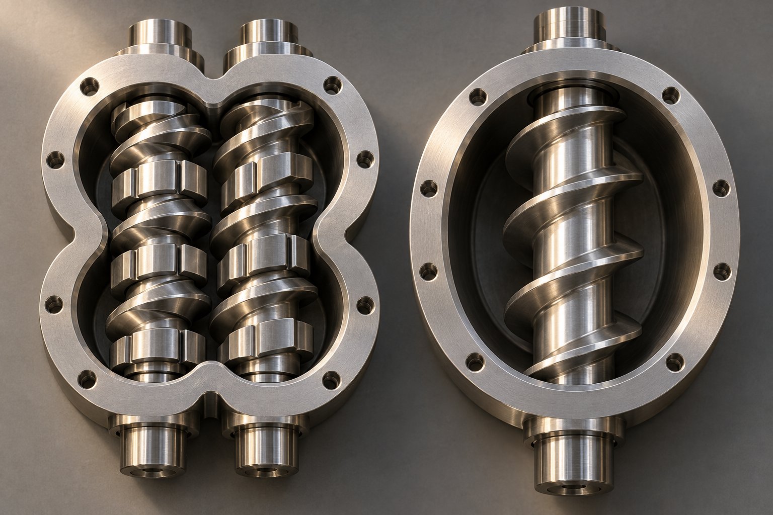
Picture what happens inside a co-rotating twin-screw compounder. Two screws rotate side by side, their flights intermeshing in a figure-eight bore profile. Kneading blocks crash material between lobes at high frequency. Mixing elements shear polymer melt and disperse fillers through narrow intermeshing gaps. The screws do not simply convey material forward the way a single-screw flight does — they actively knead, mix, and compound it under significantly higher specific energy input. That aggressive mixing action translates directly into more severe wear conditions on every metal surface involved.
Several factors compound the material challenge in twin-screw systems:
- Higher specific torque loads: Twin-screw extruders operate at higher torque density relative to their screw diameter. The mechanical stress on each screw element — especially kneading blocks and mixing elements — exceeds what a single-screw flight of comparable diameter experiences. This demands tougher substrates that resist fatigue cracking under repeated high-load cycles.
- Intermeshing contact geometry: In a co-rotating twin-screw barrel, the two screws wipe each other and the barrel wall continuously. The tight clearances between intermeshing flights, between kneading block lobes, and between screw tips and the figure-eight bore create multiple high-shear contact zones — each one a potential site for abrasive, adhesive, or corrosive wear.
- Localized wear concentration: Unlike a single-screw flight that distributes wear relatively evenly along the barrel bore, twin-screw kneading blocks concentrate extreme shear into short axial zones. A five-element kneading block section compounding 40% glass-fiber-filled nylon can experience wear rates several times higher than the conveying elements upstream.
- Modular screw construction: Most twin-screw extruders use a building-block screw design — individual elements (conveying, kneading, mixing, discharge) keyed onto a central shaft. Each element is a separate component that must independently resist the wear conditions in its zone. A conveying element in the feed section faces solid pellet friction, while a kneading block in the compounding zone faces fully dispersed glass fibers at peak shear. One material grade rarely covers all zones optimally.
These demands push twin-screw element materials well beyond standard nitriding steels. For general compounding — color masterbatch, filler masterbatch, unfilled engineering plastics — nitrided tool steels like H13 or D2 provide acceptable service life. For high-filler compounding operations — 30%+ glass fiber, heavy mineral loading, or abrasive recycled streams — powder metallurgy tool steels (CPM 9V, CPM 10V) or even fully sintered tungsten carbide elements become necessary. Some twin-screw compounders processing 60-70% calcium carbonate filler masterbatch run kneading blocks manufactured entirely from tungsten carbide to survive the relentless abrasive environment.
The twin screw barrel itself introduces another layer of material complexity through segmented construction. Rather than a single monolithic cylinder, most twin-screw barrels consist of multiple short barrel sections bolted together end-to-end. Each segment can be individually lined with a different bimetallic alloy matched to the processing conditions in that specific zone. A practical example: a corrosion-resistant nickel-based liner in the venting zone — where volatile acids from flame-retardant decomposition concentrate and attack exposed metal — paired with an abrasion-resistant iron-boron or tungsten-carbide liner in the compounding zone where fillers are being dispersed at maximum shear. This zone-specific liner strategy is unique to twin screw and barrel architecture and allows far more precise material optimization than a single-screw barrel permits.
Single-Screw Material Selection Advantages
Single-screw extruders operate in a comparatively gentler mechanical regime. A single continuous flight wraps helically around one screw shaft, conveying material forward through drag flow against a smooth cylindrical bore. There are no intermeshing elements, no kneading block impact zones, and no figure-eight bore geometry concentrating wear into narrow bands. The continuous flight geometry distributes wear more evenly across the full barrel length, and the lower specific energy input generates less aggressive shearing action on both screw and barrel surfaces.
What does this mean for material selection? It means standard extruder screw barrel material combinations cover a broader application range on single-screw machines than they do on twin-screw equipment:
- Nitrided 38CrMoAlA screws remain viable for a wider variety of resins and moderate filler loadings — applications that would already demand tool steel or PM grades on a twin-screw compounder.
- Standard iron-boron bimetallic barrels handle most filled compounds effectively, because the wear is distributed along the full bore rather than concentrated at specific kneading zones.
- Surface treatments like nitriding and chrome plating retain their usefulness longer because the per-unit-area contact severity is lower than in intermeshing twin-screw geometry.
Single-screw machines also avoid the modular element complexity of twin-screw systems. One screw, one barrel, one material pairing decision — rather than optimizing different element grades for each functional zone along the screw length. This simplicity reduces procurement complexity, spare parts inventory, and the risk of mismatched materials between adjacent components.
The trade-off, of course, is processing capability. Single screw extruders cannot match the dispersive mixing, self-wiping, and devolatilization performance of twin-screw compounders. But for pipe extrusion, sheet extrusion, film blowing, and profile extrusion — where the resin arrives pre-compounded and the extruder's job is primarily to melt and pressurize — a single-screw machine with well-chosen nitriding-grade steel and a bimetallic barrel delivers excellent economics.
| Category | Twin-Screw Extruder | Single-Screw Extruder |
|---|---|---|
| Typical Screw Element Material | Tool steels (H13, D2), powder metallurgy (CPM 9V/10V), or full tungsten carbide for high-filler compounding | Nitriding steels (38CrMoAlA) for general use; tool steels (D2, H13) for filled compounds |
| Barrel Liner Approach | Segmented barrels with zone-specific bimetallic liners (e.g., corrosion-resistant in vent zones, abrasion-resistant in compounding zones) | Single monolithic barrel with uniform bimetallic liner or nitrided bore |
| Dominant Wear Pattern | Concentrated at kneading blocks and mixing elements; figure-eight bore apex zones experience highest abrasion | Distributed more evenly along barrel length; feed zone and metering section show highest wear |
| Screw-to-Barrel Clearance Sensitivity | Extremely tight tolerances required at intermeshing zones; small clearance increases significantly degrade self-wiping and mixing efficiency | Tolerances important but less critical; gradual clearance increase causes progressive (not sudden) performance loss |
| Material Upgrade Flexibility | Modular elements allow upgrading only high-wear zones (e.g., WC kneading blocks) while retaining standard elements elsewhere | Entire screw must be upgraded as a single unit; no zone-specific element replacement |
| Cost Implications | Higher per-component cost; premium materials often necessary even for moderate applications; offset by zone-specific replacement economics | Lower baseline material cost; standard grades viable for wider application range; full screw replacement simpler and faster |
The takeaway is not that twin-screw machines are inherently more expensive to maintain — it is that they demand more precision in material selection. A single-screw extruder can tolerate a "good enough" material choice across a forgiving range of applications. A twin-screw compounder punishes material compromises quickly, concentrating wear in zones where inadequate alloys fail within months rather than years. Matching the right material grade to each functional zone — and maintaining the differential hardness hierarchy between screw elements and barrel liner in every zone — is what separates profitable twin-screw operations from those trapped in a cycle of premature component replacement.
Regardless of which machine type you operate, the ultimate test of any material decision is what happens on the production floor over time. Wear does not announce itself with alarms — it builds silently inside the barrel bore and across screw flight surfaces, gradually degrading output quality and efficiency until the damage becomes impossible to ignore. Knowing how to detect, measure, and interpret that wear before it reaches the costly failure stage is the next essential skill.
Recognizing Material Wear and Failure Before It Costs You
Wear inside an extruder does not send you an alert. There is no warning light on the control panel when your screw flight tips lose 0.003 inches of hardfacing or when your barrel bore drifts out of tolerance. Instead, the damage accumulates silently — shift after shift, batch after batch — hiding behind small process adjustments that mask the real problem. You bump screw speed up a few RPM to hold throughput. You nudge barrel temperatures down to compensate for rising discharge melt temperature. You accept a slight increase in dimensional variation on the extrudate and move on. By the time the symptoms become impossible to ignore, the wear has already progressed far enough to compromise product quality, slash output efficiency, and potentially damage the more expensive component in the system.
Connecting material selection decisions to observable, measurable outcomes on the production floor is the bridge between metallurgical theory and operational reality. Whether you are running a single-screw extrusion line or monitoring injection molding screws in a high-cavitation cell, the physical evidence of wear follows the same patterns — patterns that tell you not just how much wear has occurred, but what type of wear is driving it and whether your current material grade is up to the job.
Barrel Bore Diameter Measurement and Wear Thresholds
The barrel bore is your baseline reference. Every other wear measurement — screw outside diameter, flight clearance, leakage flow — depends on knowing the actual internal diameter of the barrel at multiple points along its length. When the bore wears, the clearance between screw flight tips and the barrel wall increases. That growing gap allows polymer melt to leak backward over the flights instead of being pushed forward, directly reducing pumping efficiency.
How significant is this effect? Consider the data from extrusion research published by Plastics Technology: on a 100-mm diameter screw running 1 MI polyethylene at 150 kg/hr, a flight clearance increase from 0.005 inches to 0.016 inches per side forced the operator to raise screw speed significantly just to maintain rate. Discharge temperature climbed from 236 degrees Celsius toward 246 degrees Celsius — a level too high for blown film. The result was a mandatory rate reduction of about 13%, directly cutting line profitability. That entire cascade of problems originated from bore wear measured in thousandths of an inch.
To measure bore diameter accurately, you need a telescoping gauge or a bore micrometer — not a simple caliper. Measurements should be taken at multiple axial positions along the barrel length and at two perpendicular orientations (0 and 90 degrees) at each position. Oval wear patterns, where one axis wears more than the other, indicate screw deflection or misalignment driving one-sided contact. Uniform increases across the full bore length suggest generalized abrasive wear from dispersed fillers.
What tolerances signal replacement? Industry guidelines for a standard plasticating extruder specify the nominal flight clearance as the screw diameter divided by 1,000. A 3.5-inch extruder, for example, ships with roughly 0.004 inches of clearance per side. Common replacement thresholds include:
- 2x original clearance: Conservative threshold used for critical-duty applications — medical tubing, optical film, tight-tolerance profiles — where even minor output variation is unacceptable
- 4x original clearance: A widely used general guideline for standard extrusion applications, though some non-critical processes like corrugated pipe can tolerate even more
- Complete loss of bimetallic liner or hard facing: At this point, the soft base metal is exposed, and wear rates accelerate exponentially regardless of application criticality
A useful benchmark from field experience: an injection molding barrel or extrusion barrel with an iron-based bimetallic liner will typically last approximately three times the service life of the screw running inside it — assuming the differential hardness principle has been applied correctly. If your barrel is wearing out at the same rate as your screws, something is wrong with your material pairing, alignment, or both.
Reading Screw Flight Wear Patterns to Diagnose Root Causes
Pulling the screw for inspection reveals a physical record of everything that has been happening inside the barrel. Flight surfaces, root diameters, and transition zones each tell a different part of the story — if you know how to read them.
Uniform flight height reduction is the signature of abrasive wear. When you measure the screw outside diameter along its length and find a consistent, gradual decrease in flight height — especially across the metering section where fillers are fully dispersed in the melt — abrasion from glass fibers, minerals, or contaminants is the primary driver. The worn surfaces typically appear smooth and polished rather than rough. This pattern is the most common wear mode in injection molding screws and extrusion screws processing filled compounds, and it tells you that your current flight material or hardfacing is being mechanically eroded faster than your production schedule can tolerate.
Localized pitting on flight tips and screw root surfaces signals corrosive attack. Unlike the smooth, polished appearance of abrasive wear, corrosion leaves a rough, cratered texture — small irregular pits where acid by-products have dissolved the metal surface. You will often notice this pattern most severely in specific zones: near vent ports where volatile acids concentrate, in the compression section where rising temperatures accelerate chemical reactions, and on the trailing side of flights where stagnant melt pockets allow prolonged acid contact. Surface discoloration — dark staining, bluish tinting, or a mottled appearance — frequently accompanies corrosive pitting.
Smearing, galling, and scoring marks indicate adhesive wear from metal-to-metal contact. These look distinctly different from abrasive or corrosive damage. You will see material transfer — one metal smeared onto the other's surface — along with deep scoring lines oriented in the direction of screw rotation. Galling marks tend to appear at specific axial locations rather than distributed evenly, pointing to localized screw deflection or bore misalignment. Hardfacing that appears cracked, delaminated, or ripped off in patches rather than gradually worn down is another hallmark. If you spot these patterns, the root cause is often mechanical — poor alignment, solids wedging, or a screw running at excessive pressure — rather than purely a material deficiency.
The same diagnostic logic applies to an injection screw. Injection molding introduces additional wear complexity from the reciprocating motion and high injection pressures, but the forensic evidence on the flight surfaces follows identical patterns: smooth polish means abrasion, pitting means corrosion, scoring means adhesive contact. Knowing which pattern dominates tells you whether your next replacement screw needs harder hardfacing, more corrosion-resistant alloys, or a geometry redesign to reduce deflection — three very different material solutions for three visually distinct failure signatures.
Building an Inspection Schedule Based on Material Grade
Here is the practical reality: a nitrided 38CrMoAlA screw processing 30% glass-filled nylon will wear through its thin hardened case far sooner than a CPM 9V screw in the same application. A chrome-plated injection molding barrel running PVC will lose its protective layer faster than a nickel-based bimetallic barrel. Different material grades have different service life expectations — and your inspection schedule should reflect those expectations rather than following a one-size-fits-all calendar.
The goal is to catch wear before it crosses the threshold where performance degrades noticeably or — worse — before a worn screw damages the barrel. A structured checklist, tied to material grade and application severity, keeps you ahead of the curve:
- Establish baseline measurements at installation. Record the new screw outside diameter at every flight along its length, the barrel bore diameter at multiple axial positions and orientations, and the as-installed flight clearance. These numbers are your reference for every future comparison.
- Set initial inspection intervals by material grade and application. For nitrided screws processing filled or reinforced resins, inspect every 2,000-4,000 operating hours until you establish a wear trend. For tool steel or PM screws in the same application, intervals of 4,000-6,000 hours are a reasonable starting point. For unfilled commodity resins on nitrided components, annual inspections (roughly 6,000-8,000 hours) are typically adequate. Twin-screw kneading elements in high-filler compounding may need inspection every 3,000-5,000 operating hours regardless of material grade.
- Track wear rate per inspection cycle. Do not just record absolute measurements — calculate the rate of change. A screw losing 0.001 inches of flight height per 1,000 hours has a predictable remaining service life. A sudden acceleration in wear rate signals that the nitrided case has worn through, a coating has failed, or a new contaminant has entered the resin stream.
- Correlate wear measurements with process data. Cross-reference screw and barrel wear against trends in specific rate (output divided by screw speed), discharge melt temperature, motor current, and die pressure stability. A declining specific rate accompanied by rising discharge temperatures is a strong confirmation that flight clearance has increased beyond optimal limits.
- Inspect the barrel bore whenever the screw is pulled. Never pull a screw without measuring the barrel. Bore measurements confirm whether the differential hardness principle is working — the screw should show more wear than the barrel. If both are wearing at comparable rates, your material pairing needs revision.
- Document hardfacing condition separately from base metal wear. On hardfaced screws, check for cracks, delamination, and exposed base metal on flight tips. Industry practice recommends that a screw should never be refurbished more than three times, because repeated weld overlay application deteriorates the base material and increases delamination risk.
- Maintain a spare screw ready for immediate installation. When inspection data shows the current screw approaching its wear limit, the spare goes in without extended downtime. The worn screw is refurbished or replaced on a planned schedule rather than under emergency pressure.
- Adjust inspection frequency based on accumulated trend data. After two or three inspection cycles, you will have enough data to predict remaining service life with confidence. Tighten intervals as components approach end-of-life thresholds. Extend intervals for premium material grades that demonstrate slower-than-expected wear rates.
A disciplined inspection program transforms material wear from a surprise expense into a predictable, budgetable operating cost. It also generates the data you need to evaluate whether your current extruder screw barrel material choices are performing as expected — or whether a material upgrade would pay for itself through extended service intervals and reduced unplanned downtime. That cost-performance analysis, combined with a systematic framework for making the upgrade decision, is the final piece of the material selection puzzle.
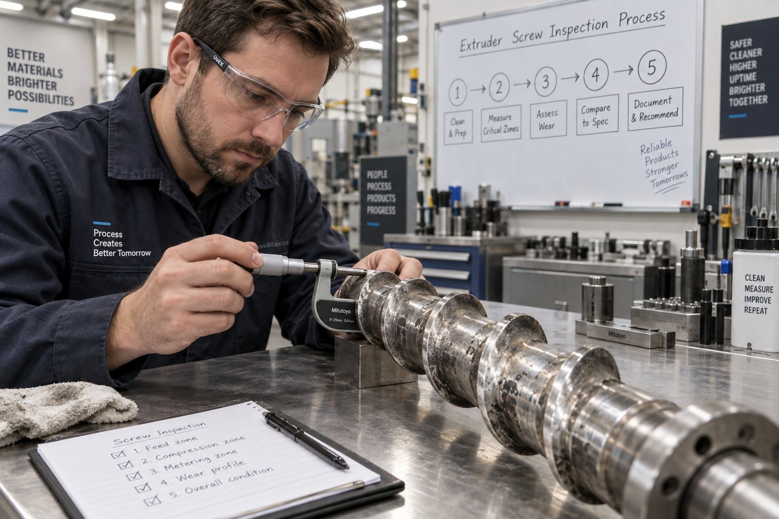
Selecting the Right Extruder Screw Barrel Material with a Systematic Framework
Inspection data tells you what is happening inside the machine. A systematic framework tells you what to do about it. Every material grade, liner alloy, surface treatment, and pairing strategy discussed throughout this article collapses into a repeatable decision process — one that replaces guesswork with engineering logic. Whether you are specifying components for a new extrusion line, replacing worn screws on a davis standard extruder, or upgrading barrel liners on us extruders running recycled feedstocks, the same five-step sequence applies.
A Five-Step Material Selection Framework
Think of this as a diagnostic flowchart. Each step narrows the field of viable options until you arrive at a material pairing matched to your specific processing reality — not a generic recommendation from a catalog.
- Identify your polymer and filler system completely. List the base resin, every filler and reinforcement (type and loading percentage), all additives including flame retardants and colorants, and whether recycled or contaminated feedstocks are part of the mix. A 30% glass-filled PA66 with a halogenated flame retardant package is a fundamentally different material challenge than 30% glass-filled PA66 without it — the first demands simultaneous abrasion and corrosion resistance, while the second is primarily an abrasion problem.
- Diagnose the dominant wear mechanism. Use the forensic indicators covered earlier — smooth polished wear for abrasion, pitting and discoloration for corrosion, scoring and galling for adhesive contact. If you are specifying materials for a new application with no wear history, base the diagnosis on the polymer chemistry and filler characteristics. PVC means corrosion leads. Glass fiber above 20% means abrasion leads. Recycled streams with unknown contaminants mean you plan for worst-case abrasion.
- Select barrel liner material first. The barrel is the more expensive and harder-to-replace component, so it sets the performance ceiling. Match the liner alloy family to the dominant wear mechanism: iron-boron for abrasion-dominant applications, nickel-based alloys for corrosion-dominant environments, and tungsten-carbide-loaded liners for extreme abrasion or dual-threat conditions. For twin-screw compounders, specify zone-specific liners where processing conditions vary along the barrel length.
- Select screw material using the differential hardness principle. The screw must be softer than the barrel liner at the contact interface — always. Choose a screw substrate and surface treatment that delivers adequate wear resistance for the application while remaining the sacrificial partner. A nitrided 38CrMoAlA screw pairs well with an iron-boron bimetallic barrel. A CPM 9V powder metallurgy screw with Stellite hardfacing pairs with a tungsten-carbide-lined barrel. Never reverse the hardness hierarchy.
- Specify surface treatments for critical zones. The feed section deserves special attention — solid pellet friction creates the fastest-developing wear pattern on most extruders. Hardfaced flight tips in the feed zone, combined with an abrasion-resistant barrel liner in that section, deliver outsized returns. For corrosive resins, PVD coatings (CrN or TiN) on the screw body add chemical protection without adding thickness that could affect clearances. Layer these treatments strategically rather than applying a single treatment uniformly.
Material selection is a system-level decision. Screw geometry, barrel design, material grade, and surface treatment must all be considered together — not in isolation. Optimizing one variable while ignoring the others leaves performance and money on the table.
Building the Cost-Performance Case for Material Upgrades
Procurement teams and plant managers often resist premium material specifications because they see only the higher purchase price on the quote. The job of the process engineer is to reframe the conversation around total cost of ownership — and the numbers almost always favor the upgrade.
Consider a real-world comparison. A nitrided 38CrMoAlA screw processing 30% glass-filled nylon might last 8,000-10,000 hours before flight clearance forces replacement. An H13 tool steel screw, ion nitrided and hardfaced with tungsten carbide on the flight tips, costs roughly 40-60% more upfront — but delivers 20,000-25,000 hours or more in the same application. The upgraded screw eliminates one full replacement cycle, saves the associated downtime (typically 8-16 hours per screw change including cooldown, removal, installation, and restart), and avoids the scrap and quality losses that accumulate as the nitrided screw's thin case wears through. As experts in optimized screw replacement confirm, properly designed replacement screws have paid for themselves within months — one documented case achieved a 30% reduction in additive costs alone, recovering the screw and barrel investment in under a year.
Build your cost-performance case around these quantifiable metrics:
- Cost per kilogram of processed output: Divide total component cost (purchase price plus installation downtime cost) by the kilograms of acceptable product produced before replacement. Premium materials almost always deliver a lower cost-per-kilogram despite their higher purchase price.
- Avoided downtime value: Multiply the hours saved from fewer replacements by your line's hourly production value. A davis-standard extruder producing $500/hour in finished product loses $4,000-$8,000 per screw change — costs that disappear when the replacement interval doubles.
- Quality consistency: Worn components produce wider process variation. The cost of off-spec material, customer complaints, and rework often exceeds the component cost itself but rarely appears on the same budget line. Quantifying this hidden cost strengthens the upgrade justification significantly.
- Barrel protection value: Every month of additional screw life — achieved through better screw materials — is also a month of reduced risk to the far more expensive barrel. A screw upgrade that costs $3,000 more but prevents a $15,000 barrel replacement pays for itself five times over.
When to Partner with a Material Selection Specialist
The five-step framework works well for straightforward applications where the polymer system is well-characterized and the wear mechanism is clear. Real-world processing, though, is rarely that simple. Dual-threat compounds combining abrasive fillers with corrosive chemistries, recycled feedstocks with unpredictable contamination profiles, and high-performance engineering resins pushing temperature and pressure limits all create material selection puzzles that benefit from specialized metallurgical and processing expertise.
This is where working with a knowledgeable design partner pays dividends. NANHAIYA's Custom Screw Design Services help plastic processing companies navigate exactly these complexities — matching screw geometry, barrel design, material selection, and surface treatment to specific polymers, output targets, and production requirements. Rather than selecting each variable in isolation, NANHAIYA evaluates the full system holistically: base material, liner alloy, surface engineering, screw geometry, and processing conditions are all optimized together so that no single decision undermines the others.
The value of this approach is not just technical precision — it is risk reduction. A material recommendation backed by application-specific analysis eliminates the trial-and-error cycle that costs processors thousands in premature replacements before they land on the right combination. For any operation where the stakes are high — expensive barrel liners, demanding filler loadings, tight product tolerances, or aggressive production schedules — investing in expert material selection guidance upfront is one of the highest-return decisions you can make.
Extruder screw barrel material selection is ultimately a bet on the future. Every hour your equipment runs, the materials you chose are either earning their keep or quietly accumulating costs that will arrive on your desk months or years from now. A systematic, evidence-based approach — grounded in wear mechanism diagnosis, metallurgical science, and total cost of ownership thinking — is the only reliable way to make sure that bet pays off.
Frequently Asked Questions About Extruder Screw Barrel Materials
1. What is the best material for an extruder screw and barrel?
There is no single best material — the right choice depends on your polymer, filler type, and dominant wear mechanism. For unfilled commodity resins like PE and PP, nitrided 38CrMoAlA steel offers cost-effective performance. For glass-filled nylons or mineral-loaded compounds, tool steels such as H13 or powder metallurgy grades like CPM 9V paired with bimetallic barrel liners provide superior service life. For corrosive resins like PVC, nickel-based barrel liners and corrosion-resistant screw coatings are essential. A specialist like NANHAIYA can evaluate your full processing environment — resin chemistry, filler loading, output targets — and recommend a matched screw geometry, barrel liner, and surface treatment combination through their Custom Screw Design Services (https://www.nhyscrews.com/services/custom-screw-design).
2. Why does the extruder screw wear faster than the barrel?
This is intentional, not a defect. Engineers apply the differential hardness principle, deliberately specifying the screw to be softer than the barrel liner. When inevitable metal-to-metal contact occurs — from screw deflection, thermal expansion, or solids wedging — the softer screw wears preferentially. Since screws are significantly cheaper and faster to replace than barrels (often three to five times less costly), designing the screw as the sacrificial component minimizes total system replacement costs over the equipment's lifespan. If both components wear at comparable rates, the material pairing is incorrect and should be revised.
3. How often should extruder screws and barrels be inspected for wear?
Inspection frequency should be tied to material grade and application severity rather than a fixed calendar. Nitrided screws processing filled or reinforced resins warrant inspection every 2,000 to 4,000 operating hours. Tool steel or powder metallurgy screws in similar applications can extend to 4,000 to 6,000 hours. Unfilled commodity resins on nitrided components typically need annual checks at around 6,000 to 8,000 hours. Twin-screw kneading elements in high-filler compounding may need inspection every 3,000 to 5,000 hours. Always measure both the screw outside diameter and barrel bore diameter at multiple axial positions, and track the rate of change between cycles to predict remaining service life.
4. What is a bimetallic extruder barrel and when do you need one?
A bimetallic barrel features a wear-resistant alloy liner centrifugally cast inside the barrel bore, metallurgically bonded to the base steel body. The liner — typically 1.3 to 1.5 mm thick — provides two to four times the wear-resistant depth of a nitrided surface. You need a bimetallic barrel whenever you process filled or reinforced polymers above roughly 15 to 20 percent loading, corrosive resins like PVC or fluoropolymers, or recycled feedstocks with unpredictable contaminants. Iron-boron liners handle general abrasion, nickel-based liners resist corrosive chemistries, and tungsten-carbide-loaded liners address extreme abrasion from high glass-fiber content.
5. How do twin-screw extruder material requirements differ from single-screw extruders?
Twin-screw extruders impose significantly harsher material demands due to intermeshing element geometry, higher specific torque, and concentrated shear at kneading blocks. Standard nitriding steels that work well in single-screw applications often wear out prematurely in twin-screw compounders, which frequently require tool steels (H13, D2), powder metallurgy grades (CPM 9V, CPM 10V), or even full tungsten carbide elements for high-filler operations. Twin-screw barrels also benefit from segmented construction allowing zone-specific liners — for example, a corrosion-resistant liner at vent ports and an abrasion-resistant liner in compounding zones. Single-screw machines distribute wear more evenly, making standard bimetallic liners and nitrided screws viable across a wider application range.
Written by
Nanhaiya Technical Team
Zhoushan Nanhaiya Plastic Machinery Co., Ltd.
The Nanhaiya technical team supports screw and barrel manufacturing projects through application review, technical communication, custom manufacturing coordination, and production and quality control.
Discuss Your Application
Related Articles
More insights on screw barrel technology and plastics processing.

What Nobody Tells You About Screw Barrel For Plastic Machine Design
Oct 10, 2026
Learn how screw barrel for plastic machine design affects melt quality, throughput, and wear life. Covers geometry, resin matching, troubleshooting, and sourcing.
Read Article
Single Screw Extruder for Sheet: Stop Guessing, Start Specifying
Oct 9, 2026
Learn how to specify a single screw extruder for sheet production. Covers screw geometry, resin-specific processing, troubleshooting, and maintenance best practices.
Read Article
PE Pipe Extruder Machine: What Datasheets Won't Tell You
Oct 9, 2026
Learn how a PE pipe extruder machine works, key specs explained, material grade selection, maintenance tips, and buyer guidance beyond the datasheet.
Read ArticleLooking for something else?
Search by material, symptom or product and jump straight to the relevant page.
These are navigation suggestions based on keyword matching — not a quotation, not a delivery commitment, and not a substitute for engineering review. Final specification is confirmed by our engineers against your drawings and processed material.
Need help with screw barrel selection?
Share your machine model, processed material and application. Our team can help with pricing and technical support.