

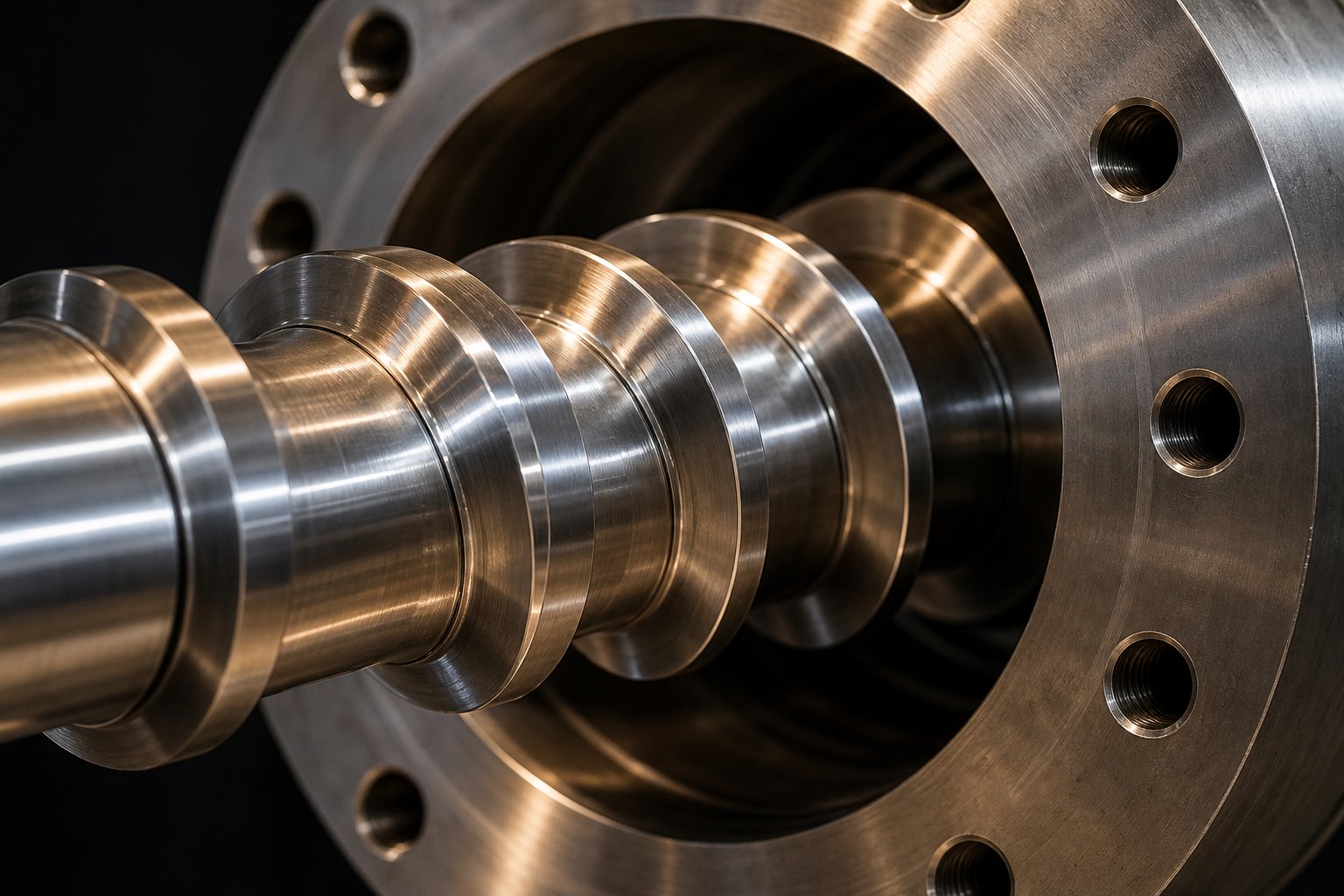
What Is an Extruder Screw Barrel and Why It Matters
An extruder screw barrel is the two-component assembly at the core of every plasticating process. It consists of a helical screw rotating inside a precision-bored barrel, working together to convey, compress, melt, and meter polymer into a die or mold. Think of it as the engine of any extrusion or injection molding machine - without it, raw plastic pellets have no way of becoming a finished product.
The screw's helical flights create channels that drag material forward, while the barrel provides containment, heat transfer surfaces, and a wear-resistant bore. Together, they transform solid resin into a homogeneous, pressurized melt ready for shaping. Whether you are a plastic processor running production, an equipment builder designing a new line, or a maintenance team keeping machines healthy, understanding how extruder screws and barrels function is not optional - it is foundational.
What an Extruder Screw Barrel Actually Does
Every extruder screw performs three jobs across its length: it feeds solid pellets from the hopper, melts them through a combination of shear heating and conducted barrel heat, and then meters the molten polymer at stable pressure toward the die. The barrel, far from being a passive tube, actively participates. Its heated zones supply thermal energy, its cooled sections prevent premature melting, and its bore surface creates the friction needed to move solids forward. The running clearance between the screw flight tips and barrel bore - typically just the screw diameter divided by 1,000 per side - is what makes the entire pumping mechanism work.
Why This Component Demands Attention
Here is the reality most processors underestimate: output rate, melt quality, energy efficiency, and part-to-part consistency all trace directly back to the condition and design of the screw and barrel.
The screw barrel assembly accounts for the majority of energy input and thermal management in any extrusion or injection molding process.
A worn or poorly matched extruder screw does not just reduce throughput - it raises melt temperatures, introduces quality defects, and drives up energy costs. Yet many plants treat these components as generic spare parts, swapping in whatever fits the bore diameter without considering geometry, metallurgy, or resin compatibility.
That gap between how critical this system is and how casually it gets treated is exactly what this article addresses. In the sections ahead, you will find a lifecycle approach that covers selection, design, operation, wear diagnosis, and replacement - because each stage shapes the next, and treating them in isolation is where most processors go wrong.
How the Screw and Barrel Work Together as a System
Most processors think about the screw and the barrel as two separate purchases - one rotates, one stays still, and they happen to share the same machine. That mindset leads to mismatched replacements, overlooked wear patterns, and process problems that seem mysterious but are actually predictable. The barrel and screw form a single integrated system, and every meaningful process outcome - from output stability to melt quality - depends on how well these two components interact.
The Functional Relationship Between Screw and Barrel
Imagine trying to pump water through a pipe with a loose-fitting piston. No matter how hard you push, fluid leaks backward and efficiency collapses. The same principle applies inside an extruder barrel. The barrel provides containment, heat transfer surfaces, and a wear-resistant bore. The screw, rotating within that bore, provides mechanical work through two flow mechanisms: drag flow and pressure flow.
Drag flow is the primary mechanism that moves material forward. The rotating screw flights act like a conveyor, pulling polymer along the barrel wall toward the die. Pressure flow works in the opposite direction - as resistance builds at the die end, material tries to flow backward through the screw channels. The net output of any extruder is the difference between these two flows, and both depend entirely on how the screw and barrel interact as a matched pair.
The clearance between the screw flight outer diameter and the barrel inner diameter is where this relationship becomes critical. On new equipment, this gap typically falls between 0.005 and 0.010 inches (0.125 to 0.25 mm), scaled slightly for very small or very large machines. That tight tolerance is not arbitrary. It controls leakage flow - the third and least desirable flow pattern, where material escapes backward over the flight tips instead of moving toward the die. As veteran extrusion engineer Allan Griff notes, some wear beyond original clearances is usually harmless and may even be helpful, but processors should confirm a real problem exists - such as overheating because the screw must run faster for the same output - before committing to rebuilding or replacing.
Beyond clearance, the barrel's inner surface finish and the screw's flight geometry must be matched for effective solids conveying, melting, and metering. A barrel bore that is too smooth in the feed section will not grip pellets effectively. A screw with mismatched flight depths relative to the barrel's thermal profile will melt too early, too late, or unevenly. These components are designed as a system, and treating them as interchangeable parts from different suppliers or specifications often introduces the very inconsistencies processors blame on resin quality or operator error.
How Clearance, Surface Finish, and Thermal Transfer Interact
Three variables govern the barrel-to-screw relationship at a fundamental level, and they do not operate independently. Clearance, surface finish, and thermal pathways interact continuously along the entire length of the extruder feed barrel and beyond.
Start with clearance. As the gap between the flight lands and barrel bore increases - whether from wear or manufacturing tolerance - leakage flow rises. Material that should be moving forward instead slips backward over the flight tips, reducing net throughput and generating excess shear heat in the process. You will notice declining output at constant screw speed, rising melt temperatures, and eventually, visible quality problems in the finished product. A tighter-than-necessary fit creates its own issues: excessive heat generation in the clearance zone and accelerated wear on both surfaces.
Surface finish plays a less obvious but equally important role. In the feed section, the extruder barrel needs a rougher internal surface to grip solid pellets and push them forward. The screw root, by contrast, benefits from a smoother finish - even chrome plating in some cases - to prevent pellets from sticking and rotating with the screw instead of advancing along the channel. This differential friction principle is what drives solids conveying: high friction on the barrel wall, low friction on the screw surface. Research into solid conveying behavior in single-screw extruders confirms that friction conditions between the inner barrel wall and the conveyed material decisively influence throughput. Grooved feed zones take this concept further by machining axial or helical grooves into the barrel bore to mechanically lock pellets against rotation, significantly boosting conveying rates for slippery materials like high-density polyethylene.
Thermal transfer ties everything together. The barrel conducts heat from external heater bands into the polymer melt, supplying the thermal energy needed for melting and maintaining target viscosity. Simultaneously, cooling channels - particularly around the feed throat - remove excess heat to prevent premature pellet softening and bridging. The screw itself acts as a thermal element too: depending on design, it can function as a heat sink that draws energy from the melt or, in screws with internal cooling passages, a controlled thermal regulator. Oil-heated screw cores are sometimes used for rigid PVC processing to hold the screw tip near 300 degrees Fahrenheit and prevent thermal degradation at that critical zone.
Here is how these three interaction points break down in practice:
- Clearance effects: Controls leakage flow magnitude, shear heating intensity, and pumping efficiency. Worn clearances degrade output before any other symptom appears.
- Surface finish roles: Barrel roughness in the feed zone creates the differential friction needed for solids conveying. Screw root smoothness prevents material from co-rotating with the screw instead of advancing forward.
- Thermal pathways: The barrel transfers conducted heat inward from heater bands and removes excess shear heat through cooling channels. The screw absorbs or releases heat depending on its design, influencing melt temperature uniformity across the entire channel cross-section.
When any one of these variables drifts - a barrel bore worn oval, a feed section polished smooth by abrasive filler, or a blocked cooling line raising feed throat temperature - the other two shift in response. A worn barrel and screw pair does not just lose clearance tolerance; it changes the thermal profile, alters friction dynamics, and forces operators to compensate with speed or temperature adjustments that introduce new problems.
This interconnectedness is precisely why experienced processors evaluate the barrel and screw together during inspections, not as isolated components. Understanding these relationships also shapes how screw geometry - the specific dimensions of flight depth, channel length, and compression ratio - translates into real processing performance, which varies far more than most specification sheets suggest.
L/D Ratio, Compression Ratio, and Flight Depth Explained
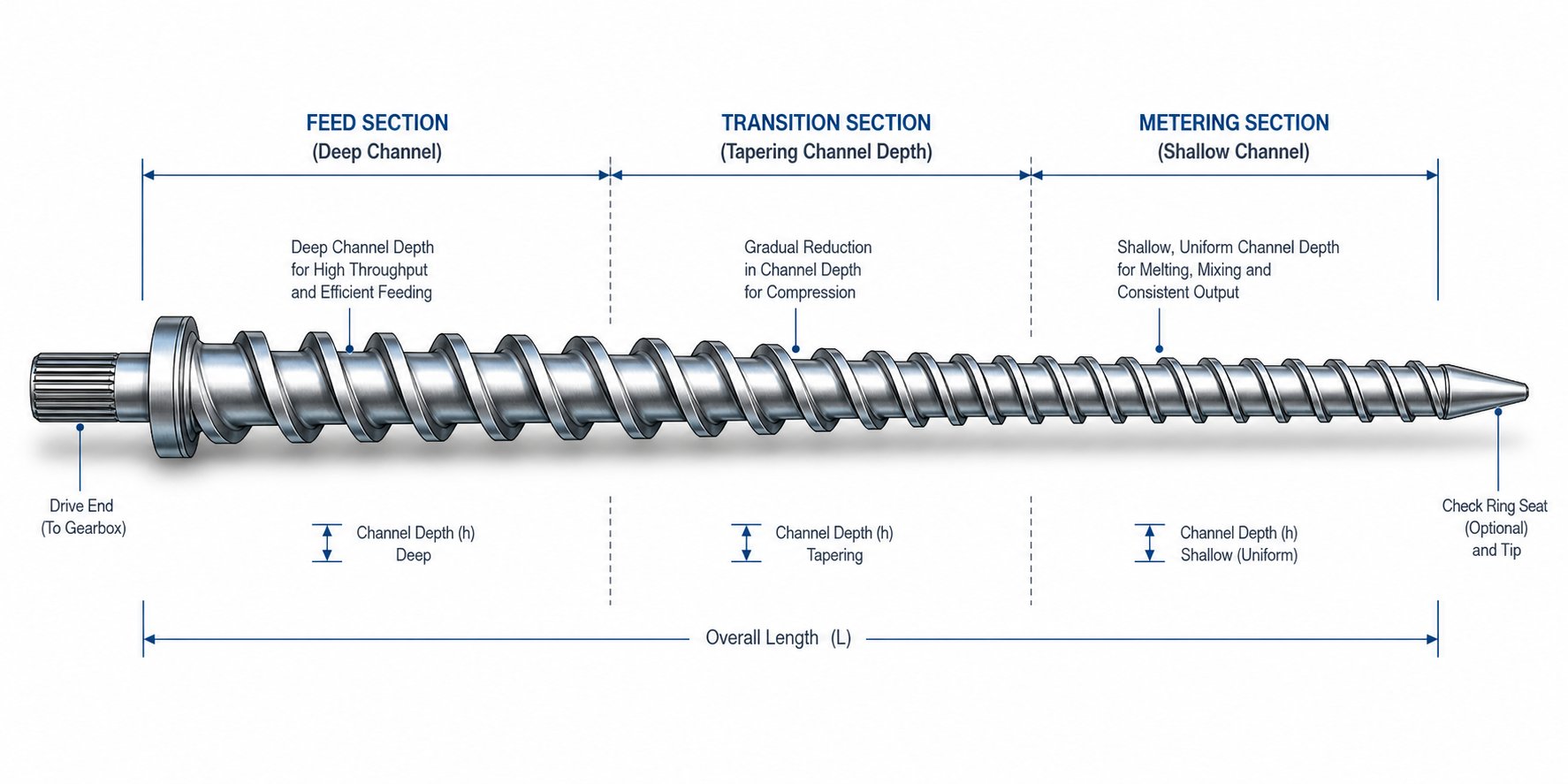
Screw geometry specifications show up on every equipment datasheet, yet most processors treat them as abstract numbers rather than levers that directly control melt quality, throughput, and energy consumption. Three parameters matter most: the length-to-diameter ratio (L/D), the compression ratio, and the metering flight depth. Each one shapes a different aspect of how polymer behaves inside the extruder screw barrel - and misunderstanding even one of them leads to process compromises that no amount of temperature adjustment can fix.
L/D Ratio and Its Effect on Melt Quality
The L/D ratio is exactly what it sounds like: the working length of the extrusion screw divided by its outer diameter. A screw that measures 90 mm in diameter and 2,700 mm in flighted length has an L/D of 30:1. Simple math, but the processing implications run deep.
Residence time is the first thing L/D controls. A longer screw keeps polymer inside the barrel for more revolutions, exposing it to more mechanical shear work and conducted heat from the barrel zones. For most single-screw extrusion applications, L/D values fall between 24:1 and 30:1, though high-performance lines - particularly those running engineering resins or demanding tight melt homogeneity - push to 32:1 or even 36:1. On the shorter end, 20:1 screws still appear in some older machines or specialty applications where minimal residence time prevents thermal degradation of heat-sensitive materials.
More length generally means better mixing and a more uniform melt temperature profile. The tradeoff? Longer screws demand higher torque from the drive motor, increase barrel heating and cooling complexity, and raise equipment cost. They also increase the opportunity for shear-sensitive polymers to degrade if screw speed is not adjusted accordingly. In practice, choosing an L/D ratio is a balancing act between melt quality and mechanical or thermal limits of the machine.
Here is a useful way to think about it: if your downstream process - whether a sheet die, blown film ring, or injection mold - consistently reveals temperature variation or unmelted particles, insufficient L/D is often a contributing factor. Conversely, if you are seeing degradation marks or yellowing on heat-sensitive resins, an excessively long residence time may be part of the problem.
Compression Ratio and Flight Depth in Practice
The compression ratio of a plastic extrusion screw defines how aggressively the channel volume decreases from the feed zone to the metering zone. It is calculated as the ratio of the feed section channel depth (H1) divided by the metering section channel depth (H2). A screw with a 10 mm deep feed channel and a 3.3 mm deep metering channel has a compression ratio of approximately 3:1.
This ratio is not just about feeding enough solid pellets into the screw. As plastics engineering references emphasize, the compression ratio also determines how much shear heating the polymer receives as it transitions from solid to melt. Every polymer has a different energy requirement for complete melting, and the compression ratio must account for viscosity behavior at varying shear rates, specific heat, and ideal exit temperature.
Higher compression ratios - in the range of 3.0:1 to 4.5:1 - deliver more mechanical energy and suit semi-crystalline polymers like polyethylene and nylon that need significant energy input to break through their crystalline melt points. Lower ratios, typically 1.5:1 to 2.5:1, are essential for heat-sensitive materials like PVC, where excessive shear generates destructive temperatures and risks HCl release.
The compression ratio injection molding screw follows the same principle but with an added consideration: the screw must also function as a reciprocating plunger during injection. This dual role often drives injection molding screws toward moderate compression ratios that balance melting efficiency with consistent shot-to-shot plasticating behavior.
Flight depth in the metering zone - the H2 value in the compression ratio equation - is equally important on its own. A deeper metering channel increases throughput capacity because more material occupies the channel per revolution. However, deeper channels also reduce the shear rate the polymer experiences, which can compromise mixing and melt temperature uniformity. Shallower metering depths boost shear intensity and improve homogeneity but limit how much material the screw can push through per turn.
To see how the shear rate calculation plays out in practice, consider a 90 mm extruder running at 60 RPM with a metering flight depth of 4.5 mm. Using the two-plates model approximation, the apparent shear rate in that zone reaches roughly 188 s-1. Cut that flight depth in half to 2.25 mm, and the shear rate doubles - fundamentally changing how the polymer behaves before it reaches the die.
The table below ties these three parameters together and maps them to practical processing outcomes:
| Parameter | Typical Range | Effect on Processing | Best Suited Resins |
|---|---|---|---|
| L/D Ratio | 20:1 to 36:1 | Controls residence time, energy input, and mixing quality. Higher L/D improves melt homogeneity but increases torque demand and risk of thermal degradation. | 24:1-30:1 for commodity polyolefins and general screw extrusion; 30:1-36:1 for engineering resins, compounds requiring intensive mixing, and high-output lines. |
| Compression Ratio (H1/H2) | 1.5:1 to 4.5:1 | Determines shear heating intensity and solids-to-melt transition rate. Higher ratios deliver more energy per unit output; lower ratios protect heat-sensitive polymers. | 3.0:1-4.5:1 for HDPE, PP, nylon, and other semi-crystalline resins; 1.5:1-2.5:1 for PVC, PVDF, and thermally sensitive materials. |
| Metering Flight Depth | 1.5 mm to 8.0 mm (varies with screw diameter) | Sets throughput capacity and shear rate. Deeper channels increase output volume but reduce shear intensity and mixing quality. Shallower channels improve homogeneity at lower throughput. | Shallower depths for color-critical or high-mixing applications; deeper channels for high-output commodity production where moderate mixing is acceptable. |
What makes these three parameters especially tricky is that they do not act alone. A high compression ratio paired with a shallow metering depth on a long L/D screw concentrates enormous shear energy into the polymer - ideal for tough-to-melt crystalline resins, potentially catastrophic for PVC. The best screw geometry always reflects a deliberate balance among all three values, matched to the specific resin family and processing platform.
That resin-specific matching extends beyond geometry into metallurgy. The same crystalline polymers that demand aggressive compression ratios often arrive loaded with glass fibers or mineral fillers that attack screw flight surfaces and barrel bores - a challenge that screw geometry alone cannot solve.
Types of Extruder Screws Compared by Application
Geometry parameters like L/D ratio and compression ratio define what a screw can do with polymer - but the overall design architecture determines what kind of processing challenge the screw is built to solve. A screw plastic extruder designed for high-speed blown film production looks nothing like one engineered for color-critical injection molded parts, even if both share identical diameters. The differences lie in flight configuration, mixing element selection, and how the design handles the transition from solid pellets to uniform melt. Yet most processors default to whatever screw came with the machine, never questioning whether a different design type would eliminate persistent quality issues or unlock higher throughput.
General-Purpose, Barrier, and Mixing Screw Designs
Three screw architectures dominate plastics processing, and each addresses a distinct set of melting and mixing requirements.
General-purpose (GP) metering screws are the workhorses of the industry. They feature the classic three-zone layout: a deep-channeled feed section that accepts solid pellets, a tapered transition or compression zone where channel depth gradually decreases to compact and melt the material, and a shallow metering zone that homogenizes the melt and builds pressure for delivery to the die. In most standard designs, each zone occupies roughly one-third of the total screw length. GP screws handle a broad range of commodity resins - polyethylene, polypropylene, polystyrene - and their simplicity makes them cost-effective and easy to maintain. The tradeoff is limited melting efficiency at high speeds, where unmelted pellets can reach the discharge end and contaminate the melt stream.
Barrier screws solve this exact problem. A secondary barrier flight begins partway through the transition zone, creating two separate channels: one for the remaining solid bed and one for the growing melt pool. The clearance between the barrier flight and barrel wall is deliberately tight - only molten polymer can pass over it into the melt channel, while solid pellets remain trapped until fully melted. This functional separation delivers more uniform melt temperatures, reduces the risk of unmelted particles, and allows higher screw speeds without sacrificing quality. Barrier designs are the go-to upgrade when a GP screw hits its melting capacity limit.
Mixing screws incorporate specialized elements - typically added at or near the end of the metering zone - to improve the homogeneity of the final melt. These elements fall into two categories. Dispersive mixers, like the widely used Maddock or LeRoy style, force the melt through narrow shear gaps ("shear dams") that break down agglomerates, pigment clusters, and gel particles. Distributive mixers, such as pineapple or pin-type elements, split and recombine melt streams repeatedly to achieve uniform temperature and composition without applying excessive shear. When you are blending color concentrates, dispersing additives, or processing recycled material with inconsistent melt viscosity, mixing elements are often the difference between acceptable parts and rejects.
The table below maps these three design types against their features, applications, and limitations:
| Screw Type | Design Feature | Primary Application | Advantages | Limitations | Ideal Resin Types |
|---|---|---|---|---|---|
| General-Purpose (GP) | Three-zone layout (feed / transition / metering) with single flight | Standard extrusion and injection molding of commodity plastics | Versatile across resin families; low cost; easy to source and replace | Limited melting efficiency at high speeds; poor mixing for color or additive blending | PP, PE, PS, ABS, and other unfilled commodity resins |
| Barrier | Secondary barrier flight separating solid bed from melt pool in the transition zone | High-output extrusion; applications demanding consistent melt temperature | Superior melting uniformity; allows higher screw speeds; virtually eliminates unmelted particles | Higher cost; must be properly matched to resin melt behavior to avoid excessive shear | Engineering resins (PA, PC, PET); high-speed polyolefin applications |
| Mixing (Dispersive) | Maddock, LeRoy, or fluted mixer elements with shear dams at the metering zone end | Processing with pigment concentrates, filled compounds, or recycled material | Breaks down agglomerates and gels; improves color dispersion and melt consistency | Increases back pressure; risk of degradation in heat-sensitive materials if shear gaps are too tight | Color-critical molding; glass-filled compounds; recycled resins |
| Mixing (Distributive) | Pineapple, pin, or cavity-transfer elements that split and recombine melt streams | Heat-sensitive blending; temperature homogenization without high shear | Uniform melt temperature and composition with minimal thermal stress | Less effective at breaking hard agglomerates; may not eliminate large solid particles | PVC; temperature-sensitive elastomers; multi-component blends |
Choosing the right architecture is not always an either/or decision. Many modern extruder screws combine barrier geometry with a mixing element at the discharge end, capturing the melting advantages of a barrier design and the homogenization benefits of a mixer in a single screw.
Single-Screw vs. Twin-Screw vs. Injection Molding Screws
Beyond flight architecture, the processing platform itself imposes fundamentally different design requirements on the screw. A single extruder screw, a twin screw barrel assembly, and an injection molding screw may share similar metallurgy and basic helical geometry, but each serves a distinct mechanical and rheological purpose.
Single-screw extruders prioritize steady-state output and melt consistency. The screw extruder operates in continuous rotation, relying on drag flow along the barrel wall to convey material from hopper to die. Because the process runs continuously, the screw design focuses on stable pressure generation, uniform melting, and consistent volumetric output. Most profile, pipe, sheet, and film extrusion lines use single-screw platforms, and the GP, barrier, and mixing designs described above all apply primarily here.
Twin-screw extruders - available in co-rotating (screws turning the same direction) and counter-rotating (screws turning in opposite directions) configurations - operate on a different principle entirely. As expert comparisons note, twin-screw systems use intermeshing screws for positive displacement, physically pumping material forward regardless of friction conditions. This makes them far superior for compounding, devolatilization, and reactive extrusion - processes where intense mixing, precise residence time control, and multi-stage processing (feeding fillers, venting moisture, adding liquid additives) are critical. The twin screw barrel arrangement also enables modular screw element configurations, allowing processors to rearrange kneading blocks, conveying elements, and mixing zones for different formulations without replacing the entire screw.
Injection molding screws face a unique challenge that no extrusion screw encounters: reciprocating motion. During plasticating, the injection molding screw rotates to melt and accumulate a shot in front of the screw tip, building material ahead of a non-return valve (check ring). Then, during injection, the screw stops rotating and plunges forward like a ram, pushing that accumulated melt into the mold cavity at pressures that can exceed 20,000 psi. This dual role - continuous-rotation plastication followed by linear injection - means the screw must deliver consistent melt quality across varying shot sizes while the non-return valve must seal reliably under extreme pressure to prevent backflow. Check-ring integration, screw tip geometry, and the ability to withstand axial thrust loads all factor into injection screw design in ways that do not apply to any screw plastic extruder configuration.
When should you choose each platform? Processing goals drive the decision:
- Choose a single-screw extruder when your process requires continuous, high-volume output of a consistent product - pipe, film, sheet, profile - using one or two well-characterized resin types. The simpler drive system, lower capital cost, and straightforward maintenance make it the default for dedicated production lines.
- Choose a twin-screw extruder when the process demands intensive mixing, multi-component compounding, devolatilization, or reactive processing. If you are incorporating high filler loadings, blending incompatible polymers, or processing moisture-sensitive feedstocks that need in-barrel venting, the positive-displacement conveying and modular screw configuration of a twin-screw are difficult to replicate on a single-screw platform.
- Choose an injection molding screw matched to your dominant resin family and shot-size range. Because injection screws must plasticize and inject, they benefit from moderate compression ratios and integrated mixing elements that ensure shot-to-shot consistency. Switching between dramatically different resins on the same injection screw often requires compromises - material-specific screws deliver better results for dedicated applications.
What unites all three platforms is a shared dependency: regardless of screw type, the materials used to build the screw and line the barrel must withstand the specific wear and corrosion challenges of the resins being processed. A perfectly designed barrier screw running glass-filled nylon will erode in months if built from the wrong steel. A twin-screw element processing PVC will corrode rapidly without proper alloy protection. Getting the design right is only half the equation - the other half is metallurgy.
Barrel and Screw Material Selection for Every Resin Family
A perfectly engineered screw geometry running the wrong metallurgy is a countdown to failure. Glass fibers chew through soft steel like sandpaper. PVC releases hydrochloric acid that eats unprotected alloys from the inside out. Flame-retardant compounds combine both attacks simultaneously. Yet processors routinely spec screws and barrels based on dimensional fit alone, ignoring whether the materials underneath can survive the resin they are actually running. The result is premature wear, unplanned downtime, and replacement costs that dwarf what proper material selection would have added upfront.
Screw and Barrel Metallurgy for Every Processing Challenge
The material options for injection molding screws and barrels - and extrusion equivalents - fall into three broad tiers, each matched to a different level of processing severity.
Nitrided steel is the baseline. Steels like 4140, 4340, or the widely used 38CrMoAlA are treated in a nitrogen-rich atmosphere to form a hard surface case roughly 0.4 to 0.7 mm deep, reaching surface hardness levels around 900 to 1000 HV. For clean, unfilled commodity resins - natural PP, PE, PS, ABS - this diffused case handles everyday sliding wear at a fraction of bimetallic cost. The thin hard layer resists moderate abrasion and maintains screw flight integrity for thousands of operating hours. Where nitriding falls short is durability against anything aggressive. Once glass fibers, mineral fillers, or corrosive off-gases start attacking, that thin case erodes through to the softer core steel underneath, and wear accelerates dramatically.
Through-hardened tool steels step up when abrasion resistance needs to extend deeper than a surface case. Steels like D2 (a high-chromium, high-carbon tool steel) and CPM 9V (a powder metallurgy vanadium-carbide steel reaching 65 to 68 HRC) offer hardness that runs through the entire cross-section, not just a surface skin. These are the go-to choices for screws processing heavily glass-filled engineering plastics, wood-plastic composites, or ceramic-loaded compounds where surface-level nitriding simply cannot keep up. The cost is higher, and machinability is more difficult, but the service life justifies it when filler loadings exceed 15 to 20 percent.
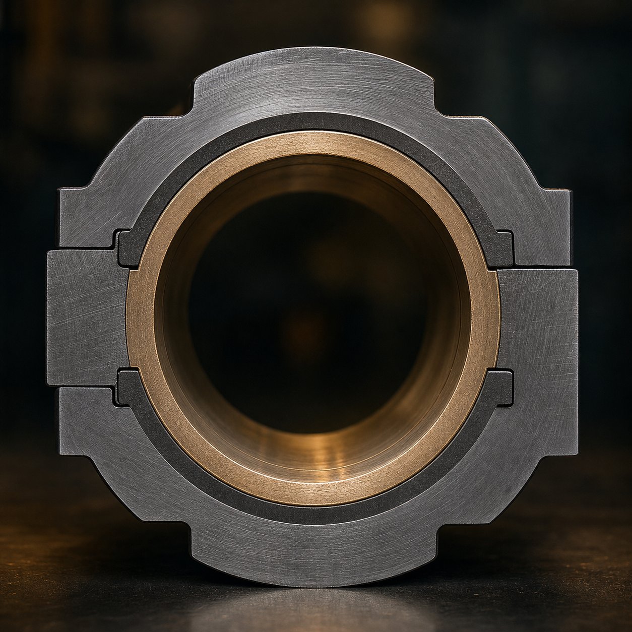
Bimetallic constructions represent the top tier. On the barrel side, centrifugal casting bonds a dense alloy lining - typically 2.0 to 3.0 mm thick - to the bore surface. Nickel-chromium-boron alloys (similar to Colmonoy-type compositions) provide corrosion resistance for chemically aggressive melts like PVC. Tungsten carbide-bearing alloys push abrasion resistance to the highest available levels, handling extreme filler loadings and operating temperatures up to 600 degrees Celsius. On the screw side, plasma transferred arc (PTA) welding deposits hardfacing alloys onto the flight lands in layers of about 1.0 to 1.5 mm. Colmonoy 56 offers a strong balance of wear and corrosion resistance. Colmonoy 83, loaded with embedded tungsten carbide particles, delivers the highest abrasion resistance even though its bulk hardness number appears lower - the carbides do the cutting resistance work, not the matrix hardness alone.
Why does PVC processing deserve special attention? When PVC degrades thermally - even slightly - it releases hydrogen chloride (HCl) gas. This acidic byproduct attacks standard carbon steels through intergranular corrosion, creating pitting and surface craters that accelerate wear and contaminate the melt with metallic particles. A twin screw and barrel assembly running rigid PVC compounds requires corrosion-resistant barrel linings (nickel-cobalt-chromium alloys) paired with screw hardfacing that prioritizes chemical resistance over pure hardness. Glass-filled engineering plastics, by contrast, present an abrasion-dominant challenge where tungsten carbide-bearing alloys on both screw and barrel earn their premium through dramatically extended service intervals.
Matching Materials to Resin Families
Sounds like a lot of variables? It is - but the decision simplifies considerably when you map your actual processing scenario to the right material combination. The table below covers the most common situations processors face, based on established plastics engineering principles and SPE technical frameworks:
| Processing Scenario | Recommended Screw Material | Recommended Barrel Lining | Key Reason |
|---|---|---|---|
| Commodity polyolefins (PE, PP, PS, ABS) - unfilled | Nitrided 4140 or 38CrMoAlA | Nitrided bore (standard) | Clean melt with no abrasive or corrosive attack; nitriding delivers adequate wear life at lowest cost |
| Rigid and flexible PVC | Corrosion-resistant hardfacing (Ni60 or Colmonoy 56 via PTA welding) | Nickel-chromium-cobalt bimetallic lining (corrosion-grade) | HCl released during processing causes aggressive corrosive attack on unprotected steel; corrosion resistance takes priority over abrasion resistance |
| Glass-filled engineering plastics (PA, PBT, PET with 15-50% GF) | Colmonoy 83 (tungsten carbide-bearing) or CPM 9V tool steel | Tungsten carbide bimetallic lining (high-wear grade) | Glass fibers act as continuous abrasive, rapidly eroding nitrided surfaces; tungsten carbide provides maximum abrasion resistance in both screw flights and barrel bore |
| Flame-retardant compounds (brominated or halogenated additives) | Colmonoy 56 or Ni60 hardfacing for combined wear and corrosion resistance | Balanced wear/corrosion bimetallic lining (e.g., nickel-chromium-cobalt-vanadium alloy) | Halogenated flame retardants release HBr and other corrosive gases while often containing abrasive mineral synergists - dual attack requires dual protection |
| Food-grade applications (FDA/EU compliance) | Stainless steel (440C or 17-4 PH, hardened martensitic grades) | Stainless steel bore or chrome-plated lining | Regulatory compliance requires non-contaminating contact surfaces; stainless alloys prevent metallic leaching into the polymer melt |
| Recycled and post-consumer feed (contaminated regrind) | Colmonoy 83 tungsten carbide hardfacing | High-wear bimetallic lining (tungsten carbide-bearing) | Contaminated regrind contains grit, metal fines, and inconsistent melt quality; abrasive protection is critical because filler content is unpredictable |
A few patterns emerge from this table. Corrosion-driven scenarios like PVC and flame-retardant processing always prioritize chemical resistance in the alloy selection, even if it means accepting slightly lower hardness numbers. Abrasion-driven scenarios - glass-filled resins, recycled material - push toward tungsten carbide on both surfaces. And clean commodity processing rarely justifies the cost premium of bimetallic construction, making nitrided screws and barrels the smart economic choice for those applications.
Material mismatch between the screw, barrel lining, and the resin being processed is one of the leading causes of premature screw barrel failure - and one of the most preventable.
The takeaway is straightforward: you would never run the wrong resin for a product's end-use requirements, so why run the wrong alloy for that resin's processing demands? A nitrided screw on a glass-filled nylon line will wear through its protective case and degrade to bare steel far sooner than a bimetallic alternative, turning what looked like a cost saving into a cycle of frequent replacements and lost production hours. The inverse applies too - specifying a premium tungsten carbide hardfacing for clean polyethylene is overpaying for protection the duty never calls on.
Getting the metallurgy right protects the screw and barrel from the resin. But the barrel itself faces an equally critical challenge that metallurgy alone cannot solve: managing the thermal energy that drives the entire melting and metering process. How heat enters, distributes, and exits along the barrel length determines whether that carefully selected alloy surface encounters polymer under controlled conditions - or under destructive thermal stress.
Barrel Heating and Cooling Zone Configurations
You can select the perfect screw geometry and pair it with exactly the right metallurgy - and still produce inconsistent melt if the barrel's thermal management is off. Temperature control along the length of an extrusion barrel is not a single setpoint. It is a carefully segmented profile, zone by zone, where each section plays a distinct role in how polymer transitions from solid pellets to a uniform, pressurized melt. Yet in many plants, barrel zone temperatures get set once during commissioning and never revisited - even when resins change, throughput targets shift, or wear alters the thermal landscape inside the machine.
Zone-by-Zone Temperature Profiling
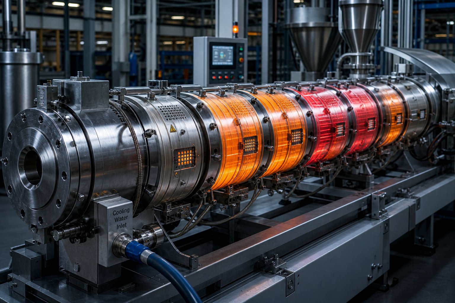
Modern extruder barrels divide into multiple independent heating zones, each controlled by its own PID-regulated heater band and thermocouple. A typical single-screw extruder with a 24:1 to 30:1 L/D ratio might have four to six barrel zones plus a die zone, while longer machines - 36:1 and above - can feature eight or more independently managed sections. This segmentation exists for a practical reason: the polymer's thermal needs change dramatically from one end of the barrel extruder to the other, and a single temperature cannot serve them all.
Feed zone. This is the one section where you often want less heat, not more. The feed zone's job is to grip solid pellets against the barrel wall and convey them forward through differential friction. If the barrel surface gets too hot here, pellets soften prematurely, smear across the wall, and bridge - blocking material flow entirely. As Graham Engineering's feed section analysis emphasizes, excessive heat in the feed throat causes partially melted material to clump against the walls, restricting or completely blocking flow into the screw channels. Removing a bridged feed throat means significant downtime, and in severe cases, safety hazards. That is why the feed zone is typically cooled rather than heated, with set temperatures running between 20 degrees C and 60 degrees C for most commodity thermoplastics - well below the polymer's softening point.
Transition zone. This is where the heavy lifting happens. As the screw channel depth decreases through the compression section, mechanical shear intensifies and the polymer begins to melt. The barrel heaters in this zone supply supplemental thermal energy to assist the melting process, and heat demand here peaks relative to any other section. Extrusion engineering guidelines recommend setting the first zone behind the feed area above the polymer's softening or crystalline melting temperature, parameterized to maximize motor load and make full use of available dissipation power. The intermediate zones between the first heated section and the die are then interpolated - stepped up in roughly uniform increments toward the target processing temperature.
Metering zone. By the time polymer reaches the metering section, it should be fully molten. The barrel's role here shifts from energy input to temperature stabilization. Even small variations in melt temperature at the metering zone translate directly into viscosity fluctuations, which cause output surging, dimensional inconsistency in the final product, and uneven die flow. The target temperature in this section generally aligns with the polymer manufacturer's recommended processing temperature. For semi-crystalline materials, that typically runs 50 to 75 degrees C above the melting point; for amorphous resins, roughly 100 degrees C above the glass transition temperature.
One detail that catches many operators off guard: the temperature displayed on the controller does not always reflect the actual melt temperature inside the channel. Thermocouple position - whether it sits in the barrel wall, at the bore surface, or in a melt-immersion probe - dramatically influences the reading. Real melt temperature is usually higher than the setpoint because of viscous shear heating that the barrel sensors cannot fully capture. Experienced processors account for this offset by applying intentional negative corrections to their zone setpoints, particularly in the metering and die zones.
The Role of Barrel Cooling Channels
Heating gets most of the attention in extrusion discussions, but cooling is equally critical to process stability - and far more often neglected. Extruder barrels use cooling in two distinct ways: feed throat cooling to prevent pellet agglomeration, and downstream cooling to remove excess shear-generated heat that would otherwise push the melt past its target temperature.
Feed throat cooling is non-negotiable for most polymers. The cast feed section design used on the vast majority of single-screw extruders in North America incorporates water-cooled passages molded directly into the casting in close proximity to the feed opening. This acts as a thermal barrier between the heated barrel and the gear reducer, keeping the throat surface cool enough to prevent low-melting-point pellets from sticking to the walls. For grooved feed zones, precise throat cooling is even more critical - the mechanical interlocking that drives high-output conveying only works if pellets remain solid and rigid as they pass through the grooves.
Downstream along the barrel, two cooling methods are common. Air cooling uses blower-driven fans mounted above the heater bands, activated by the PID controller when the zone temperature exceeds the setpoint. It is simpler to install, requires no plumbing, and provides adequate cooling for moderate shear-heat conditions. Liquid cooling circulates water or oil through channels cast or drilled into the barrel wall, delivering faster and more precise heat removal. Liquid-cooled extrusion barrels are preferred for high-speed lines, large-diameter machines, and shear-sensitive resins where even brief temperature overshoots cause degradation. The tradeoff is higher complexity, maintenance of seals and flow circuits, and the risk of channel fouling over time.
When thermal management goes wrong, the symptoms ripple through every downstream quality metric. Here are the most common problems and what they do to your process:
- Hot spots from failed heater bands or poor barrel-to-heater contact: Create localized overheating that degrades polymer, produces black specks, and causes inconsistent melt viscosity across the channel cross-section.
- Inadequate feed throat cooling: Leads to premature pellet softening, feed bridging, and output interruptions. Low-melting-point polymers like LDPE and EVA are especially vulnerable.
- Temperature overshoot in transition or metering zones: Indicates that shear heating exceeds the cooling system's capacity. The result is elevated melt temperature, reduced viscosity, potential thermal degradation, and dimensional instability in the extruded product.
- Blocked or fouled cooling channels: Reduce heat removal capacity silently over time. Processors compensate by lowering setpoints or reducing screw speed, losing throughput without realizing the root cause is a maintenance issue, not a process limitation.
- Thermocouple drift or misplacement: Causes the PID controller to regulate against inaccurate readings, creating a gap between displayed and actual barrel temperatures that compounds with every zone affected.
Proper zone configuration ties directly back to melt homogeneity and output quality. As Bausano's thermal management analysis notes, temperature directly impacts viscosity, additive mixing uniformity, surface finish, and dimensional stability of the finished product - and poor thermal control can compromise the entire production cycle. Every zone matters, but no zone operates in isolation. A feed section running too warm forces the transition zone to handle partially melted material instead of compacted solids, changing the melting mechanism and shifting energy demand downstream. An overheated metering zone cannot be corrected by cooling the die - the thermal damage is already embedded in the melt.
Getting thermal management right protects your metallurgy investment, stabilizes your melt, and extends component life. But even perfectly configured heating and cooling cannot prevent the gradual, inevitable reality that every extruder screw barrel system faces: wear. The mechanisms that erode screw flights and enlarge barrel bores often begin at the very thermal boundaries where temperature control breaks down - and recognizing those wear patterns early is what separates planned maintenance from emergency shutdowns.
Wear Mechanisms and Failure Modes in Screw Barrel Systems
Every extruder screw and barrel assembly is wearing right now. Not dramatically, not visibly - but measurably. Metal is leaving flight surfaces, barrel bores are growing wider by fractions of a thousandth of an inch per operating hour, and the tight clearances that make the pumping mechanism work are slowly opening up. The question is never whether wear is happening. It is whether you recognize what type of wear is attacking your system, how fast it is progressing, and when the economics demand action.
Most processors notice wear only when symptoms become impossible to ignore - declining output, rising melt temperature, or visible quality problems in finished parts. By that point, significant damage has already occurred, and the repair bill is far larger than it needed to be. A problem-solving approach starts earlier, with understanding the three distinct mechanisms that destroy screw and barrel surfaces and learning to read the warning signs each one produces.
Adhesive, Abrasive, and Corrosive Wear Patterns
Wear inside an extruder screw barrel is not a single phenomenon. Three fundamentally different mechanisms operate - sometimes individually, often in combination - and each one demands a different metallurgical and operational response. Treating all wear as the same generic problem is one of the most expensive mistakes a processor can make.
Abrasive wear is the most common culprit, and it behaves exactly like sandpaper against metal. Glass fibers, mineral fillers (calcium carbonate, talc, silica), and even high-concentration pigments act as hard particles that continuously scrape across screw flight lands and the barrel bore. Every revolution of the screw drags these abrasive particles through the narrow clearance zone, removing micro-layers of metal from both surfaces. The sharp, machined edges of screw flights and kneading elements gradually become rounded, smooth, and occasionally polished - a telltale visual signature that distinguishes abrasion from other wear types.
Abrasive wear rates depend on three factors: the hardness and concentration of filler particles, the screw speed and throughput rate, and the metallurgy of the screw and barrel surfaces. A 30% glass-filled nylon compound, for example, can wear through a nitrided screw's protective case in a fraction of the time it takes unfilled polyethylene to produce any measurable change. Importantly, abrasive wear correlates with the amount of material processed rather than simple operating time - a machine running filled compounds at high throughput for one shift can accumulate more wear than another running unfilled resin for three shifts.
Where does abrasion concentrate? Typically in the transition zone - where solids are compacting and large side forces push the screw against the barrel wall - and at the entry to mixing elements, where solid particles can momentarily jam in the channel and create localized pressure spikes. As extrusion troubleshooting experts note, if high levels of solids occur at the end of the melting section or at the entry to some mixers, the solids can cause momentary blockages that generate large side forces pushing the screw into the barrel wall, accelerating wear far beyond what filler abrasion alone would produce.
Corrosive wear attacks through chemistry rather than mechanical erosion. When certain polymers degrade thermally - even in small, localized hotspots - they release acidic off-gases that react with metal surfaces. PVC is the most notorious example: thermal decomposition liberates hydrogen chloride (HCl) gas, which attacks unprotected carbon steel through intergranular corrosion. The surface appears dimpled or pitted rather than smoothly worn - a visual distinction that immediately tells an experienced maintenance technician the problem is chemical, not mechanical.
Flame-retardant compounds containing brominated additives release hydrogen bromide (HBr) during processing, creating a similar corrosive environment. Fluoropolymers like PTFE and PVDF generate hydrofluoric acid (HF) at elevated temperatures - one of the most aggressively corrosive gases any injection molding barrel and screw will encounter. The damage from corrosive wear is insidious because it undermines the protective surface treatments that processors rely on. Nitrided cases and even some bimetallic linings lose integrity when acid attack eats through them from underneath, exposing the softer base metal to accelerated erosion.
Adhesive wear - often called galling - occurs when metal contacts metal directly, without the lubricating film of molten polymer that normally separates the screw flight tips from the barrel bore. Under high pressure and temperature, protective oxide layers on the metal surfaces break down, allowing the base metals to cold-weld momentarily at microscopic contact points. As the screw continues to rotate, those micro-welds tear apart, pulling material from one surface and transferring it to the other. The result is score marks on the barrel wall and flattened outer diameters on screw flights - damage patterns that look distinctly different from the polished rounding of abrasive wear.
What triggers adhesive wear? Insufficient lubrication between screw and barrel - which in practical terms means running the screw without enough molten polymer in the clearance gap. This happens when screws rotate at high speed between production runs with no resin being fed, when barrel alignment is off and forces one side of the screw into continuous contact with the bore, or when unfilled polyolefins are processed at excessive speeds where the thin melt film in the clearance zone breaks down. Adhesive wear is the most preventable of the three mechanisms because its root causes - alignment, operating procedures, and startup protocols - are entirely within the processor's control.
In real-world processing, these mechanisms rarely act alone. A glass-filled PVC compound delivers simultaneous abrasive and corrosive attack. A misaligned barrel running mineral-filled resin combines adhesive and abrasive wear on the same screw. Recognizing which mechanism dominates - by examining the surface appearance, identifying the resin type, and reviewing operating conditions - is the first step toward choosing the right corrective action.
Recognizing Wear Symptoms Before Failure
Wear does not announce itself with a single dramatic failure. It announces itself through a sequence of progressively worsening process symptoms - each one a signal that clearances are opening and pumping efficiency is declining. Catching these symptoms early is the difference between a planned screw change during a scheduled shutdown and an emergency teardown that costs days of lost production.
The progression follows a predictable pattern. As the gap between screw flight tips and barrel bore increases, leakage flow - material slipping backward over the flight lands instead of moving forward - grows proportionally. This leakage directly reduces the extruder's specific rate (output per screw revolution), which is the single most reliable indicator of wear progression. A new screw might produce 12 pounds per hour per RPM. As wear progresses, that number drops to 11, then 10, then lower - even though nothing else about the process has changed.
Here are the warning signs in order of severity, from earliest detectable to imminent failure:
- Gradual decline in specific rate: Output per RPM decreases over weeks or months. The operator compensates by increasing screw speed to maintain throughput, often without realizing why the adjustment was necessary.
- Rising melt temperature at constant output: Higher screw speeds combined with increased leakage flow over worn clearances generate additional shear heat. Discharge temperature increases because the film thickness on the barrel wall grows as flight clearance widens, reducing the heat-transfer coefficient and trapping more shear energy in the melt.
- Increased energy consumption: The drive motor works harder to push the same amount of material as pumping efficiency drops. Monthly energy cost per pound of output creeps upward.
- Melt pressure instability and output surging: Worn clearances create uneven flow conditions in the metering zone. The die sees pressure fluctuations that translate to dimensional variation in the finished product - gauge bands in film, wall thickness variation in pipe, or weight inconsistency in injection molded parts.
- Visible surface degradation on screw components: When the screw is pulled for inspection, flight tips appear rounded (abrasive wear), pitted (corrosive wear), or scored and galled (adhesive wear). Hardfacing may be partially or completely worn through, exposing softer base metal underneath.
- Unacceptable part quality despite process adjustments: At advanced wear levels, no combination of temperature, speed, or backpressure settings can compensate for the lost pumping efficiency and degraded melt quality. This is the point where many processors finally recognize the problem - but the economic damage of reduced rates and scrap has been accumulating for months.
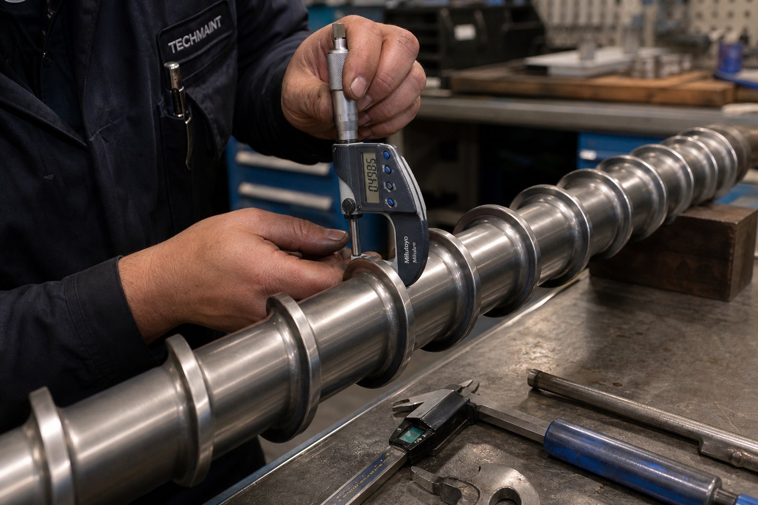
Quantifying wear requires measurement, not guesswork. For the screw, a micrometer measures the outer diameter across the flight tips at multiple points along the screw length. A parallel test bar spanning two flights provides accurate outside diameter readings that can be compared against original specifications. For the barrel, a bore gauge inserted from each end measures the internal diameter as far down the bore as the tool can reach. Comparing both sets of measurements against baseline values reveals exactly where wear is concentrated and how much clearance has been lost.
How much wear is too much? The answer depends on the application. Industry guidelines suggest that when flight clearance reaches four times the original value, most applications will show measurable performance degradation. Critical-duty processes - medical tubing, optical film, tight-tolerance injection molding screws - may demand screw replacement at just twice the original clearance. Noncritical applications like corrugated pipe can sometimes tolerate significantly greater wear before product quality suffers. As a general guideline for screw elements, replacement is typically warranted when the outside diameter has decreased by approximately 5% from the starting diameter over three-quarters of the element's length, while barrel liners warrant attention when bore diameter has increased by 5% over a length of one diameter.
One additional consideration shapes replacement economics: barrel liners with iron-based bimetallic construction typically last about three times the service life of a screw. This means a processor running a demanding application might go through three screw replacements or refurbishments before the barrel itself needs attention. Tracking both measurements in parallel prevents the costly mistake of installing a new screw into a worn barrel - which simply accelerates wear on the new component.
Establish baseline diameter measurements for both screw flights and barrel bore at the time of installation - without that reference point, no subsequent measurement can tell you how much wear has actually occurred or how fast it is progressing.
A spare screw kept in storage eliminates the extended downtime that turns a routine replacement into a production crisis. When the current screw reaches its wear limit, the spare goes in immediately and the worn screw goes out for evaluation. It can often be refurbished - hardfacing reapplied, flights rebuilt to original dimensions - though a screw should never be refurbished more than three times, because repeated welding deteriorates the base material and increases the risk of hardfacing delamination during operation.
Catching wear early, measuring it accurately, and acting on the data before process quality deteriorates - that is the maintenance discipline that separates plants running at peak efficiency from those constantly chasing unexplained output losses. But measurement and diagnosis are only part of the equation. How the screw and barrel are installed and aligned in the first place, and how consistently they are monitored afterward, determines whether wear progresses at its natural minimum rate or gets artificially accelerated by preventable mechanical stresses.
Installation, Alignment, and Preventive Maintenance for Your Screw and Barrel
Diagnosing wear accurately only pays off if the screw and barrel were installed correctly in the first place. A misaligned assembly accelerates every wear mechanism covered above - abrasive, corrosive, and adhesive - by forcing the screw into sustained contact with one side of the barrel bore. The result is lopsided wear patterns, bent screws, heater band damage, and drive loads that climb for reasons nobody can trace until the machine is torn down. Davis-Standard's alignment guidance documents real-world consequences including premature wear, broken screws, unstable barrels, and thermocouple shearing - all from improper alignment that went unchecked after commissioning.
Proper Alignment and Assembly Procedures
Alignment starts at the drive end, not the die end. The barrel must be aligned to the drive quill of the gearbox - no exceptions. Trying to align by leveling is inaccurate because it only addresses the vertical plane and tells you nothing about the actual centerline of the rotating drive shaft. The correct procedure uses an optical or laser alignment scope inserted into the drive quill. With the quill rotated, the barrel and feed throat are adjusted to match a fixed centerline using barrel supports or feed throat mounting faces.
Here is where thermal expansion catches processors off guard. Steel expands at roughly 0.000006 inches per inch per degree Fahrenheit. A 4.5-inch, 36:1 barrel heated uniformly to 450 degrees F grows approximately 0.320 inches longer compared to room temperature. If barrel supports prevent free axial expansion, the barrel bends - destroying alignment and creating the exact metal-to-metal contact that drives adhesive wear. Proper support systems must allow the screw tube to slide freely as temperature changes, use non-corrosive joint materials like brass to prevent freezing, and remain rigid enough to maintain position without tipping as the barrel grows.
Before reassembly, verify screw straightness by rolling on V-blocks or using dial indicators. Inspect the barrel bore with a bore gauge at multiple points, recording dimensions against baseline values. Follow proper torque sequences for barrel bolting, and after the first heat-up, place dial indicators at 90-degree angles on the discharge flange to check for deflection. Noticeable movement signals a support malfunction, burned-out heater bands creating unbalanced heating, or structural weakness in the base.
Preventive Maintenance and Wear Monitoring
Installation is a single event. Maintenance is what keeps that initial alignment and tight clearance working for years instead of months. The processors who avoid emergency shutdowns are not running better equipment - they are tracking the same measurements at regular intervals and acting before trends become failures.
A practical plastic extruder screw maintenance program follows this sequence:
- Record baseline dimensions at installation: Measure and log screw flight OD at multiple locations along the screw length, barrel bore ID from both ends, and the date and operating hours at installation. Without this reference, no future measurement has context.
- Monitor process indicators weekly: Track specific rate (output per RPM), discharge melt temperature, drive amperage, and melt pressure stability at a standard recipe. Upward trends in temperature and amperage or downward trends in specific rate signal progressing wear.
- Inspect heater bands and thermocouples monthly: Check resistance values on all heater bands, verify thermocouple readings against a calibrated reference, and look for signs of band migration or poor barrel contact. Temperature drift above plus or minus 3 degrees C is an early warning of heater or sensor problems that compound thermal management issues.
- Perform bore and flight measurements every 500 to 1,000 operating hours: Pull the screw and measure flight tip diameters with a micrometer. Gauge the barrel bore at matching locations. Compare against baselines and previous readings to calculate wear rate per operating hour.
- Conduct a full screw pull and visual inspection annually or at 4,000 to 6,000 hours: Clean the screw using non-destructive tools - brass scrapers and copper gauze, never aggressive steel brushes that score polished surfaces and create new hang-up zones. Document wear patterns, photograph damaged areas, and assess whether the screw and barrel remain within serviceable tolerances.
- Plot wear trends and project replacement windows: With three or more measurement intervals logged, wear rate per thousand hours becomes predictable. Use that rate to schedule replacement during planned downtime rather than reacting to a quality crisis mid-run.
When measurements confirm that clearances have reached replacement thresholds, sourcing matters as much as timing. A replacement screw and barrel must match - or improve upon - the original geometry, metallurgy, and tolerance specifications for the specific machine and resin application. Specialized screw barrel manufacturers like NANHAIYA engineer custom-fit replacements to match original or upgraded specifications across extrusion and injection molding platforms, ensuring that the new components restore the tight clearances and material compatibility the process demands rather than introducing new variables.
The discipline of consistent measurement, documented baselines, and proactive replacement scheduling transforms maintenance from an unpredictable cost center into a managed investment. But knowing when to replace is only part of the decision. Knowing what to replace it with - and how to evaluate the supplier providing it - is where the lifecycle approach comes full circle.
Choosing and Sourcing the Right Screw Barrel Solution
Replacement timing is settled, wear patterns are understood, and baseline measurements confirm the need for new components. The next question - what exactly should you buy, and from whom - is where every preceding decision converges into a single purchasing moment. Get it right and the new screw barrel restores peak performance for years. Get it wrong and you repeat the same wear cycle, sometimes faster than before.
Matching Screw Barrel Specifications to Your Process
Think of specification as a decision tree with three branches. Your resin dictates metallurgy. Your product geometry and output target dictate L/D ratio and compression ratio. Your processing platform - single-screw extrusion, twin-screw compounding, or injection molding - dictates the screw design type. Every chapter in this article has fed one of those branches, and the table below consolidates them into a single reference for US extruders and global operations alike:
| Decision Factor | Key Considerations | Recommended Action |
|---|---|---|
| Resin compatibility and metallurgy | Abrasive fillers demand tungsten carbide hardfacing; corrosive resins (PVC, flame-retardant compounds) require nickel-alloy barrel linings; clean commodity polymers perform well on nitrided surfaces | Match the alloy to the actual resin threat - not the cheapest option or the most expensive one. Review the material selection table in the metallurgy section before finalizing any order. |
| Geometry match (L/D, compression ratio, flight depth) | Output rate, melt quality, and energy efficiency all trace to these three parameters. A mismatch causes problems no temperature adjustment can fix. | Specify geometry based on your dominant resin family and throughput target. If upgrading from the original OEM design, ensure the new geometry is validated for your barrel thermal profile. |
| Processing platform | Single-screw extrusion screws prioritize steady-state output; twin-screw elements handle compounding, devolatilization, and reactive processing; injection molding screws must integrate non-return valves and handle reciprocating motion | Confirm the supplier can engineer for your specific platform. A vendor that only builds single-screw components may not understand the modular element configurations a twin-screw line requires. |
| Tolerance and clearance standards | Flight-to-bore clearance controls leakage flow and pumping efficiency. Loose tolerances on replacement parts negate the investment immediately. | Request documented dimensional inspection reports with every shipment. Compare delivered dimensions against baseline specs before installation. |
| OEM vs. upgraded replacement | OEM-equivalent replacements restore original performance; upgraded specifications (barrier flights, improved metallurgy, optimized compression ratio) can exceed it | Evaluate whether the original design was actually optimal. Many processors discover that a spec upgrade during replacement delivers measurable gains in output or quality. |
Processors who acquire used single screw extruders or pick up a used twin screw extruder for sale on the secondary market face an additional layer of complexity: the screw and barrel that ship with used equipment are almost always partially worn. Baseline measurements on arrival are essential, and in many cases, ordering replacement components sized to the actual barrel bore - rather than assuming nominal dimensions - prevents the clearance mismatch that undermines performance from day one. The same logic applies when sourcing a Davis-Standard extruder for sale or any other pre-owned machine from established OEMs. Assume nothing about component condition until you have measured it.
What to Look for in a Screw Barrel Supplier
Not every supplier that offers screws and barrels actually engineers them. The market includes full-service manufacturers with in-house metallurgical capability and trading companies that resell components from unknown workshops with no traceability. The difference shows up in service life, dimensional accuracy, and what happens when something does not fit. Here are the qualifications that separate a genuine engineering partner from a parts broker:
- Custom engineering capability: The supplier should design screw geometry and select materials based on your resin, throughput, and quality requirements - not just replicate a drawing.
- Material and metallurgy options: Look for in-house nitriding, bimetallic barrel casting, PTA hardfacing, and tool steel machining. A supplier limited to one material tier cannot serve diverse applications.
- Documented tolerance standards: Every screw and barrel should ship with dimensional inspection data - flight OD, bore ID, straightness, and concentricity measurements - traceable to calibrated instruments.
- Cross-platform support: Your facility may run single-screw extruders, twin-screw compounders, and injection molding machines. A supplier that covers all three platforms simplifies procurement and ensures consistent quality across your operation.
- Lead time and inventory depth: Unplanned replacements happen. A supplier with stocking programs or rapid manufacturing capability minimizes the production gap between failure and fix.
- OEM and replacement experience: The best suppliers serve both equipment builders and end-user processors, understanding both original specification requirements and the real-world upgrade opportunities that come with replacement cycles.
For processors evaluating custom or replacement options, NANHAIYA's product center offers screw and barrel configurations across single-screw, twin-screw, and injection molding platforms - built specifically for plastic processors, equipment manufacturers, and maintenance teams seeking components engineered to match their exact application requirements.
The screw barrel sits at the intersection of every variable that determines extrusion and molding success: resin behavior, thermal management, mechanical wear, and process economics. Treating it as a commodity purchase - grabbing whatever fits the bore - ignores the engineering that makes the difference between a machine that runs and one that performs. Specify deliberately, source from manufacturers who understand the application, measure what you receive, and maintain what you install. That lifecycle discipline is what most processors get wrong - and what separates consistent, profitable operations from the ones constantly chasing unexplained problems.
Frequently Asked Questions About Extruder Screw Barrels
1. What is the typical clearance between an extruder screw and barrel?
On new equipment, the radial clearance between the screw flight outer diameter and the barrel inner diameter generally falls between 0.005 and 0.010 inches (0.125 to 0.25 mm) per side, scaled slightly for very small or very large machines. This tight gap controls leakage flow - polymer slipping backward over the flight tips instead of advancing toward the die. When wear doubles or quadruples this original clearance, pumping efficiency drops noticeably, melt temperature rises, and output per screw revolution declines. Processors should record baseline clearance at installation and track changes over time using bore gauges and flight-tip micrometers to schedule replacements proactively.
2. How do I know when my extruder screw and barrel need replacement?
Several progressive symptoms signal advancing wear. The earliest indicator is a declining specific rate - lower output per RPM at constant conditions. Next, melt temperature climbs even without setpoint changes because increased leakage flow generates extra shear heat. Drive amperage rises as the motor compensates for lost efficiency, and melt pressure becomes unstable, causing dimensional variation in finished products. Quantitatively, industry guidelines suggest replacement when flight clearance reaches roughly four times the original value, or when screw flight OD has decreased by about 5% over three-quarters of its length. Specialized manufacturers like NANHAIYA (nhyscrew.com/products) can engineer exact-fit replacements matched to your barrel bore and resin requirements.
3. What is the best screw compression ratio for PVC extrusion?
PVC processing typically requires a low compression ratio in the range of 1.5:1 to 2.5:1. The reason is thermal sensitivity - PVC degrades quickly under excessive shear, releasing corrosive hydrogen chloride gas that damages both the screw and barrel. A lower compression ratio reduces the mechanical energy input per unit of output, keeping melt temperatures within the safe processing window. In contrast, semi-crystalline polymers like HDPE and nylon need higher compression ratios (3.0:1 to 4.5:1) to supply the energy required to break through their crystalline melt points. Always pair the correct compression ratio with corrosion-resistant metallurgy when running PVC.
4. What causes premature wear in extruder screw barrels?
Three distinct mechanisms drive premature wear. Abrasive wear comes from glass fibers, mineral fillers, and pigments physically eroding screw flights and barrel bore surfaces - it correlates with material throughput rather than simple operating time. Corrosive wear results from acidic off-gases released by resins like PVC (HCl) and flame-retardant compounds (HBr), which attack unprotected metal through chemical pitting. Adhesive wear, or galling, occurs when metal-to-metal contact happens without adequate polymer lubrication in the clearance zone, often caused by barrel misalignment or dry-running the screw. Mismatched metallurgy - such as using a standard nitrided screw for glass-filled nylon - dramatically accelerates all three mechanisms.
5. What is the difference between a barrier screw and a general-purpose screw?
A general-purpose (GP) screw uses a classic three-zone layout with a single flight: a deep feed section, a tapered transition zone, and a shallow metering zone. It handles a wide range of commodity resins at moderate speeds but can allow unmelted particles to reach the discharge end at higher throughputs. A barrier screw adds a secondary flight in the transition zone that physically separates the remaining solid bed from the growing melt pool. Only fully molten polymer can pass over the barrier flight into the melt channel, virtually eliminating unmelted particles and producing more uniform melt temperatures. Barrier screws cost more and must be carefully matched to the resin's melt behavior, but they unlock higher screw speeds without sacrificing quality - making them the preferred upgrade when a GP screw reaches its melting capacity limit.
Written by
Nanhaiya Technical Team
Zhoushan Nanhaiya Plastic Machinery Co., Ltd.
The Nanhaiya technical team supports screw and barrel manufacturing projects through application review, technical communication, custom manufacturing coordination, and production and quality control.
Discuss Your Application
Related Articles
More insights on screw barrel technology and plastics processing.

What Nobody Tells You About Screw Barrel For Plastic Machine Design
Oct 10, 2026
Learn how screw barrel for plastic machine design affects melt quality, throughput, and wear life. Covers geometry, resin matching, troubleshooting, and sourcing.
Read Article
Single Screw Extruder for Sheet: Stop Guessing, Start Specifying
Oct 9, 2026
Learn how to specify a single screw extruder for sheet production. Covers screw geometry, resin-specific processing, troubleshooting, and maintenance best practices.
Read Article
PE Pipe Extruder Machine: What Datasheets Won't Tell You
Oct 9, 2026
Learn how a PE pipe extruder machine works, key specs explained, material grade selection, maintenance tips, and buyer guidance beyond the datasheet.
Read ArticleLooking for something else?
Search by material, symptom or product and jump straight to the relevant page.
These are navigation suggestions based on keyword matching — not a quotation, not a delivery commitment, and not a substitute for engineering review. Final specification is confirmed by our engineers against your drawings and processed material.
Need help with screw barrel selection?
Share your machine model, processed material and application. Our team can help with pricing and technical support.