

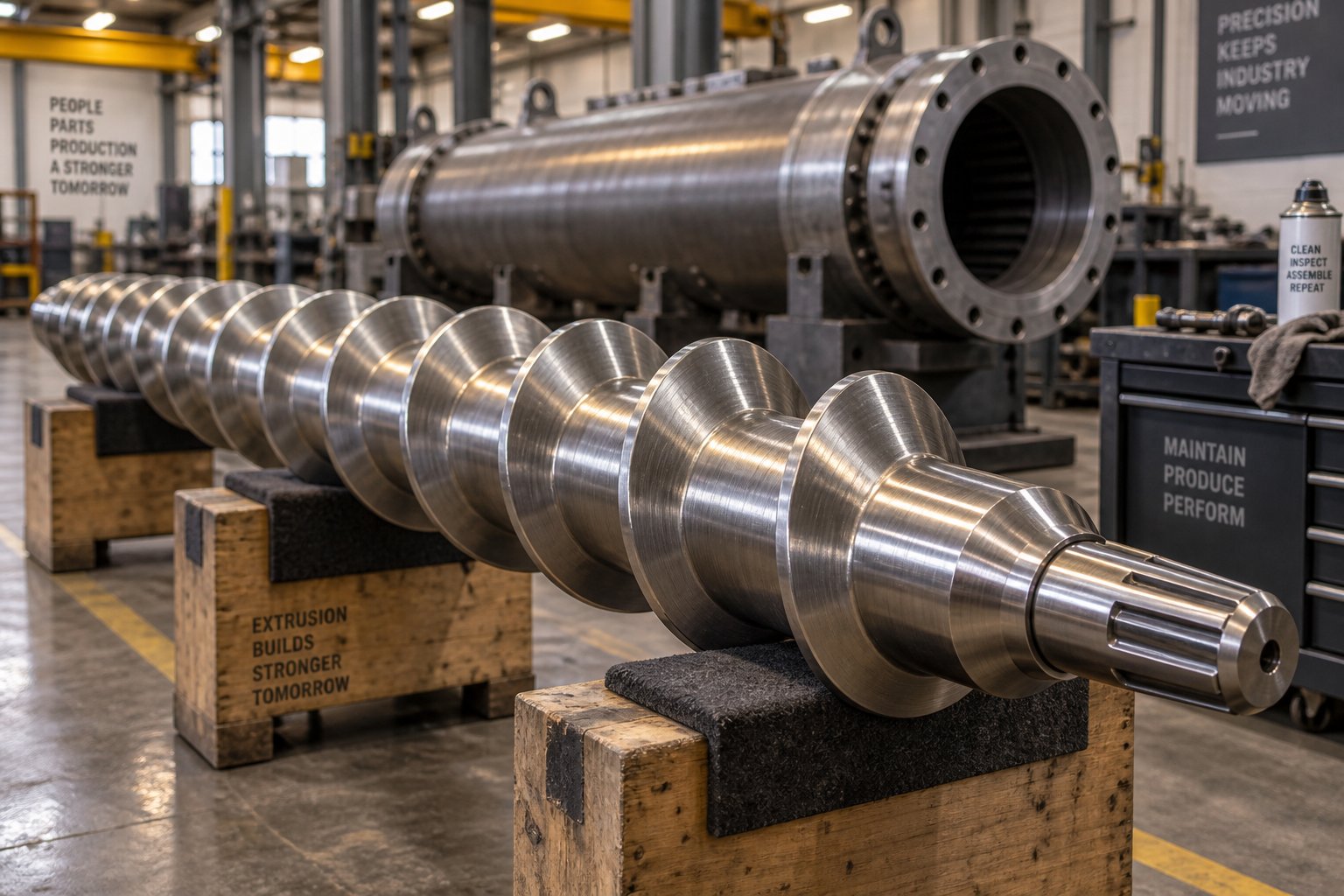
Understanding Extruder Screw and Barrel Replacement
Imagine your extrusion line gradually losing throughput, melt quality slipping shift by shift, and energy bills creeping upward with no obvious cause. You bump screw speed a little higher, nudge barrel temperatures, maybe accept a slightly higher scrap rate. These small compensations feel manageable — until the day they aren't. That tipping point is where extruder screw and barrel replacement enters the conversation, and getting it right can mean the difference between a line that pays for itself and one that quietly drains profitability.
What Extruder Screw and Barrel Replacement Actually Involves
At its core, extruder screw and barrel replacement is the process of removing worn plasticating components from an extrusion line and installing new or remanufactured parts to restore output quality, throughput, and energy efficiency. It applies to both single-screw and twin-screw configurations — from straightforward metering screws to complex segmented twin-screw element sets and their matching barrel sections.
The screw and barrel form the heart of any plasticating unit. They are responsible for conveying, melting, mixing, and pressurizing polymer material. Over time, the critical clearances between the screw flight outside diameter and the barrel bore increase due to wear. For perspective, a new screw typically maintains a flight clearance of roughly the nominal diameter divided by 1,000 per side — about 0.004 inches on a 3.5-inch extruder. Every thousandth of an inch beyond that erodes melting efficiency, heat transfer, and pressure stability. Replacement restores those tolerances and, with them, the performance your downstream process depends on.
This isn't limited to catastrophic failure scenarios. In fact, the most costly replacements are the ones triggered by emergencies. A structured approach — treating this as a planned lifecycle event rather than a crisis response — consistently delivers better outcomes for maintenance managers, plant operators, and equipment builders alike.
Why This Process Deserves a Structured Approach
Unlike swapping a heater band or replacing a thermocouple, screw and barrel replacement touches nearly every operational function in your plant. Production scheduling has to account for downtime. Capital budgets need to absorb component and labor costs. Engineering must specify the correct metallurgy, geometry, and tolerances. And quality assurance has to validate that the new components actually deliver the expected performance improvement.
When any of these elements is handled ad hoc, the costs multiply. A misspecified screw delays the project by weeks. An unplanned shutdown during peak demand sacrifices revenue that dwarfs the price of the components themselves. Even a successful replacement can underperform if the opportunity to upgrade screw design or barrel liner material is overlooked.
Extruder screw and barrel replacement is not just a maintenance event — it is an operational decision that directly impacts product quality, energy consumption, and profitability.
The economics reinforce this point. As industry practitioners have documented, operators often compensate for wear by increasing screw speed, adjusting barrel temperatures, or raising backpressure — incremental changes that consume more energy and quietly degrade part quality until they reach a point of diminishing returns. By then, the cumulative cost of running worn components may have already exceeded what a planned replacement would have cost months earlier.
This guide covers the full lifecycle: recognizing when replacement is needed, choosing between repair and full replacement, specifying the right components, executing the swap step by step, managing downtime strategically, and building a business case that justifies the investment. Whether you're running a single-screw film line or maintaining a fleet of twin-screw compounding extruders, the framework ahead will help you turn every replacement into a measurable return.
The first question, of course, is knowing exactly when your screw and barrel have crossed from "wearing normally" to "costing you money every hour they keep running."
Recognizing When Your Extruder Screw and Barrel Need Replacement
Every extruder screw and barrel wears from the moment they first turn. The real challenge isn't acknowledging that wear exists — it's distinguishing the point where normal, tolerable wear becomes a performance and profit problem. A reliable diagnostic framework combines two complementary approaches: monitoring process performance for telltale symptoms and physically measuring components against known tolerance limits.
Performance Symptoms That Signal Worn Components
You'll often notice signs of worn extruder screw and barrel components in process data before you ever pull the screw. The most reliable early indicator is a declining specific rate — the output (lb/hr or kg/hr) divided by screw speed (RPM). When clearances between the screw flights and barrel bore widen, polymer leaks backward over the flights instead of being conveyed forward efficiently. To maintain the same throughput, operators instinctively bump screw speed higher, which drives discharge temperatures upward even without any changes to barrel heat settings.
That temperature rise isn't trivial. In a blown film application, for example, a screw with just 0.011 inches of additional wear can push discharge temperatures roughly 10°C higher at the same rate — enough to force a throughput reduction of around 13%, directly cutting line profitability and capacity. Other symptoms that map back to worn components include:
- Inconsistent melt pressure readings — wider flight clearances create unstable pressure profiles, especially in the metering zone.
- Visible extrudate defects — gels, streaks, unmelts, and voids often reflect poor melting uniformity caused by degraded screw geometry.
- Rising energy consumption — higher screw speeds and compensating backpressure adjustments consume more motor power for the same (or lower) output.
- Increasing scrap and rework rates — as industry experts have noted, operators often make incremental process adjustments that mask wear until quality falls off a cliff.
Each of these symptoms can have other root causes, of course. But when two or more appear simultaneously on a line that previously ran well, worn plasticating components deserve top priority in your troubleshooting.
Physical Inspection Indicators for Screws and Barrels
Process symptoms tell you something is wrong. Physical measurement tells you exactly how bad it is — and whether you're looking at a screw problem, a barrel problem, or both.
To measure extruder screw wear accurately, remove the screw and place it on a clean, flat surface. Using a micrometer with a parallel test bar spanning two flights, measure the outer diameter (flight OD) at multiple points along the screw length. Compare these readings against the original specification. Also measure root diameter to check for erosion of the screw channel itself — a condition common when processing glass-fiber-reinforced resins. Visually inspect for scoring, pitting, hardfacing delamination, and any bowing or bending by rolling the screw on a granite surface table.
For barrels, use a bore gauge inserted from each end, recording measurements at several depths. The standard guideline is that new flight clearance equals roughly the nominal screw diameter divided by 1,000 per side. Any clearance significantly beyond that original specification represents wear. A common rule of thumb: when flight clearance reaches four times the original value (4x), replacement planning should be well underway — though critical-duty processes like medical extrusion may warrant action at just 2x the original clearance.
The table below connects observable symptoms to the most likely worn component and a recommended response:
| Symptom or Finding | Likely Worn Component | Recommended Action |
|---|---|---|
| Declining specific rate (output per RPM) | Screw (flight OD wear) | Plan replacement |
| Rising discharge temperature at constant rate | Screw (flight clearance increase) | Plan replacement |
| Inconsistent melt pressure / surging | Screw, barrel, or both | Inspect and measure both |
| Visible scoring or galling on screw flights | Screw and barrel (adhesive wear) | Measure barrel bore; plan replacement |
| Barrel bore diameter exceeds tolerance at multiple points | Barrel | Plan barrel replacement |
| Hardfacing delamination or missing flight tips | Screw | Urgent replacement |
| Corrosion pitting on screw root or barrel liner | Both (corrosive wear) | Urgent replacement; review metallurgy |
| Extrudate gels, streaks, or unmelts | Screw (worn metering/mixing section) | Monitor; measure at next opportunity |
| Energy consumption rising with no process change | Screw, barrel, or both | Monitor; schedule inspection |
Recording these measurements at regular intervals creates a wear profile over time, which transforms reactive troubleshooting into predictable maintenance planning. The SPI Dimensional Guidelines provide a useful reference for determining when a component has exceeded serviceable wear limits.
How Processed Materials Accelerate Wear
Not all extruders wear at the same rate, and the single biggest variable is what you're running through them. Understanding how your specific materials affect screw and barrel life is essential for realistic replacement planning.
Abrasive fillers are the most common accelerators. Calcium carbonate, talc, silica, and especially glass fibers act like fine sandpaper grinding against flight tips and barrel walls. The wear concentrates in zones where solid pellets are still being conveyed and compressed — primarily the feed and transition sections. Extruder screw wear from abrasive fillers can reduce useful component life by 50% or more compared to running unfilled resin, as documented by plasticating specialists. Glass-fiber-reinforced compounds are particularly aggressive, often eroding the screw root in the rear of the channel before the fibers wet out and disperse into the melt.
Corrosive resins create a different damage pattern. PVC and fluoropolymers release acidic byproducts during processing that chemically attack iron-based metallurgies. This corrosive wear weakens the surface layer, making it vulnerable to mechanical erosion that follows. You'll see widespread pitting rather than the localized grooves typical of abrasive wear.
Combined abrasion and corrosion — think flame-retardant compounds with mineral fillers — delivers the worst of both mechanisms simultaneously. These applications demand the highest-grade barrel liners and screw hardfacing alloys, and they compress replacement intervals dramatically.
Recognizing which wear mechanism dominates your application shapes every downstream decision: how aggressively to monitor, what metallurgies to specify for replacement components, and whether repair can deliver acceptable life or full replacement with upgraded materials is the only sensible path forward.
Repair vs. Refurbish vs. Replace: A Decision Framework
Knowing that your screw or barrel has crossed the wear threshold is only half the equation. The harder question — the one that lands on the maintenance manager's desk — is what to do about it. Should you repair the existing component, invest in refurbishment, or order a brand-new replacement? Each path carries different cost implications, turnaround times, and performance outcomes. Choosing the wrong one doesn't just waste money; it can put you right back in the same situation six months later.
The smart approach is to treat this as a structured decision rather than a gut call. Here's how to evaluate each option based on the actual condition of your components, the severity of wear, and the economics of your specific production environment.
When Repair Makes Sense
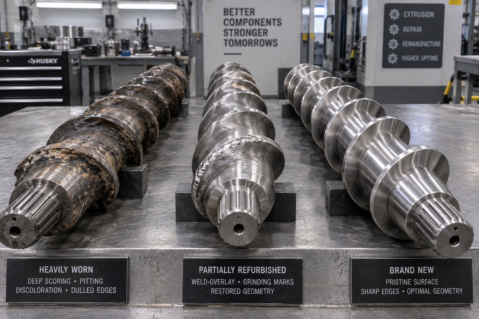
Repair is the most targeted — and typically the lowest-cost — intervention. It involves localized corrections to specific wear zones rather than reconditioning the entire component. Common screw repair techniques include weld-overlay (hardfacing) on worn flight tips, where a wear-resistant alloy containing elements like chromium, tungsten, cobalt, and boron is deposited 1 to 2 mm thick and then ground back to the required diameter. For barrels, localized repair might mean boring out a heavily worn section — often the homogenizing zone, typically 5 to 7D in length — and fitting a nitrided alloy steel bushing.
Repair makes sense when:
- Wear is caught early and confined to one or two zones (feed section, metering zone, or a specific barrel segment).
- The screw's base metal and core geometry remain structurally sound.
- The barrel's nitriding layer is still largely intact outside the worn area.
- Production schedules demand a fast turnaround with minimal capital outlay.
The limitation? Repaired components rarely match the dimensional precision, surface finish, or service life of new parts. Weld-overlay, for instance, can introduce minor distortion or hardness inconsistencies that reduce longevity. Hard chrome plating — another common repair method — offers good corrosion and wear resistance but is prone to flaking under the mechanical stresses of extrusion. Think of repair as buying time, not resetting the clock.
When Refurbishment Is the Right Call
Refurbishment sits between repair and full replacement in both scope and cost. It involves reconditioning the entire component — not just patching a worn spot. Typical screw refurbishment includes thermal spraying the full flight surface with a wear-resistant alloy and grinding the entire screw back to specification. For barrels, refurbishment might mean boring the full length of the inner diameter to a new, larger dimension and then re-casting with a bimetallic alloy liner 1 to 2 mm thick, followed by precision finishing.
Extruder screw refurbishment vs replacement becomes a meaningful comparison when these conditions are met:
- The base material (substrate steel) is metallurgically sound — no deep corrosion, cracking, or fatigue damage.
- Dimensional loss is within reclaimable tolerances. For screws, the flight OD can be rebuilt, and the root diameter hasn't eroded past engineering minimums. For barrels, the bore can be opened up and re-lined without exceeding the structural wall thickness limits.
- The component hasn't already been refurbished once. Repeated thermal cycles from welding and grinding degrade base metal properties, making a second refurbishment risky.
- The original screw design still matches your current processing requirements — if you need a geometry change, refurbishment to the old spec wastes the opportunity.
Cost-effective refurbishment options like thermal spraying are generally processed by professional spraying factories at relatively low cost, while full weld-overlay reconditioning commands higher fees due to the specialized alloys and precision grinding involved. The resulting service life typically falls between that of a repaired component and a new one — a reasonable trade-off when your budget doesn't support full replacement but your wear severity exceeds what a patch repair can address.
When Full Replacement Is Unavoidable
Sometimes the math — and the metallurgy — simply don't support anything less than new components. When to replace instead of repair an extruder screw comes down to a handful of clear-cut indicators:
- Barrel bore out of tolerance beyond re-lining limits. Every barrel has a maximum bore diameter that its wall thickness can safely support. Once wear pushes past that, no liner can restore it.
- Screw core diameter reduced past engineering minimums. If the root diameter has eroded significantly — common with glass-fiber-reinforced compounds — the screw loses torsional strength and risks catastrophic failure under load.
- Corrosion damage to the base metal. Deep pitting from processing PVC, fluoropolymers, or flame-retardant compounds undermines the substrate that any repair or refurbishment would build upon. Welding over corroded steel is building on a weak foundation.
- The component has already been refurbished once. Each repair cycle introduces heat-affected zones and cumulative stress. A second refurbishment often delivers diminishing returns and shorter service intervals.
- Design requirements have changed. If your resin portfolio, throughput targets, or quality standards have evolved since the original screw was specified, replacing with an upgraded design delivers far more value than refurbishing back to an outdated geometry.
Full replacement carries the highest upfront cost, but it also resets the performance clock completely. New components deliver original-specification clearances, full metallurgical integrity, and the opportunity to upgrade screw geometry or barrel liner material — an advantage we'll explore in depth later in this article.
As the reference guidance from industry practitioners emphasizes, the real economic comparison isn't simply repair cost vs. replacement cost. It's the ratio of each option's cost to the usable service life it delivers. A repair costing 30% of a new component's price sounds attractive — until it only lasts 20% as long.
The most economical choice is the one with the lowest ratio of total cost to expected service life — not the one with the smallest invoice.
The following table puts all three options side by side to help you compare them systematically:
| Criteria | Repair | Refurbishment | Full Replacement |
|---|---|---|---|
| Typical cost relative to new component | Lowest (roughly 15-30%) | Moderate (roughly 40-60%) | Highest (100%) |
| Expected service life extension | Short — typically 25-50% of original life | Moderate — typically 50-75% of original life | Full original service life (or better with upgrades) |
| Applicable wear severity | Mild, localized wear in one or two zones | Moderate, distributed wear with sound base metal | Severe, widespread, or corrosion-compromised |
| Turnaround time | Shortest (days to a few weeks) | Moderate (weeks) | Longest (weeks to months for custom components) |
| Design upgrade opportunity | None — restores original geometry only | Limited — geometry changes possible but constrained | Full — screw design and barrel metallurgy can be optimized |
| Risk of repeat failure | Higher — root cause may not be fully addressed | Moderate — depends on base metal condition | Lowest — fresh metallurgy and full dimensional accuracy |
| Best suited for | Budget-constrained, low-criticality lines; interim fix while awaiting new parts | Mid-life components with sound substrates; stable process requirements | End-of-life components; lines processing abrasive or corrosive materials; design upgrades needed |
In practice, many maintenance teams use repair as a bridge strategy — extending a worn screw's life just long enough to source and receive a new replacement without emergency downtime. That hybrid approach works well, provided you've already initiated the specification and ordering process for the new component. Speaking of which, knowing exactly how to specify replacement screws and barrels is the step that separates a smooth swap from a drawn-out procurement headache.
How to Specify Replacement Screws and Barrels Correctly
A perfect decision to replace means nothing if the replacement part shows up and doesn't fit — or fits physically but performs poorly because a critical detail was missed in the specification. Surprisingly, this happens more often than most plant teams admit. Incomplete or inaccurate specs are one of the top causes of delayed projects, return shipments, and frustrating rework cycles. Knowing how to specify a replacement extruder screw or barrel with precision is the single most practical skill you can bring to this process.
Critical Measurements and Documentation to Gather
Before you contact any supplier, gather every dimensional and design detail you can. For the screw, you'll need to document these core parameters:
- Screw outer diameter (flight OD) — the nominal size that defines your extruder class. Standard serialized diameters range from 30 mm up through 200 mm, with 65–150 mm being the most common in production environments.
- Root diameter — measured in each functional zone (feed, transition, metering), since channel depth varies by section and directly determines the compression ratio.
- Overall length and L/D ratio — the ratio of effective screw length to diameter is a fundamental design parameter. Common L/D ratios run from 20:1 to 36:1, with values up to 43:1 in specialized applications.
- Flight pitch — the distance between adjacent flights, typically equal to the screw diameter (S = D) for standard single-flight designs.
- Number of flights — usually one for general-purpose screws, but barrier screws and some mixing geometries use two or more.
- Compression ratio — the volume ratio between the first groove in the feed section and the last groove in the metering section. This value is material-dependent. For example, rigid PVC granules typically call for a ratio around 2.5, while polyethylene film screws may require ratios above 4.0.
- Shank configuration and drive-end details — the spline, key, or coupling geometry that connects the screw to the gearbox. Getting this wrong means the screw physically cannot be installed.
For barrels, you need an equally thorough set of data points: bore diameter, overall length, flange dimensions and bolt patterns, feed-port geometry (size, shape, location), thermocouple port positions, heater-band zone locations, cooling channel layout, and liner material specification.
Your starting point should always be OEM documentation — original drawings, specification sheets, or machine manuals. But what if those documents are unavailable? This is common with older equipment. As engineering teams specializing in OEM replacement projects confirm, a used barrel or screw sample is often the most valuable reference when drawings are missing. Engineers can perform CMM (coordinate measuring machine) inspection and CAD reconstruction to reverse-engineer the original geometry — provided the sample's unworn reference features are still intact. Photographs, machine nameplates, and any maintenance records you've kept also help fill the gaps.
What Information Your Supplier Needs
Even if you've gathered perfect dimensional data, your supplier needs context beyond the geometry to manufacture or source the correct part. Imagine ordering a screw with the right diameter and length but the wrong metallurgy for your resin — it could wear out in half the expected time. Here's the complete checklist of what information a screw barrel supplier needs to quote and produce accurately:
- Machine make, model, and year — helps the manufacturer cross-reference known configurations and identify potential compatibility issues.
- Original component dimensions — all the measurements outlined above, ideally with tolerances noted.
- Material being processed — the polymer type, filler content, reinforcement type, and any additives. This drives every metallurgy and surface-treatment decision.
- Operating temperatures and pressures — barrel zone setpoints and typical melt pressure ranges.
- Required metallurgy or surface treatments — nitriding depth requirements, bimetallic liner alloy preferences, hardfacing alloys for screw flights, or carbide coatings for extreme wear applications.
- Screw design details — barrier flight geometry, mixing section type and location, vent port locations (for vented barrel configurations), and any proprietary design features.
- Matching component information — if you're replacing only the screw, provide the barrel's current bore diameter. If replacing only the barrel, supply the screw's current flight OD. Proper clearance between the two is critical.
- Any desired design modifications — perhaps you want to add a mixing section, change the compression ratio for a new resin, or upgrade to a barrier screw design.
- Special requirements — such as material certifications, hardness test reports, dimensional inspection reports, or specific delivery timelines.
Incomplete specifications are the single biggest source of costly delays and misfitting parts in replacement projects. A supplier can't compensate for information you didn't provide — and assumptions made to fill gaps rarely match your actual requirements. Take the time to assemble a complete data package before requesting quotes, and you'll avoid the frustrating back-and-forth that stretches lead times by weeks.
Specifying Barrels with Equal Rigor
Screws tend to get most of the attention during replacement planning, partly because they're more visually accessible and partly because screw design has a more obvious connection to processing performance. But barrel specification deserves equal rigor — and neglecting it is a mistake that can undermine the entire replacement investment.
The most consequential barrel specification decision is extruder barrel liner material selection. The liner is the working surface that contacts the polymer melt, and its composition must be matched to your processing environment. Three main categories cover the vast majority of applications:
- Nitrided steel — the baseline option. A gas or plasma nitriding process creates a hardened case approximately 0.4–0.6 mm deep with surface hardness of 950–1100 HV on nitriding-grade alloy steel (typically 38CrMoAlA or equivalent). This is cost-effective and fully adequate for clean, unfilled polyolefins and standard PVC at moderate throughput. The key limitation: once abrasive wear penetrates that thin hardened case, the soft core is exposed and wear accelerates rapidly.
- Bimetallic alloy liners (centrifugally cast) — a wear-resistant alloy is centrifugally cast inside the barrel shell at approximately 1100°C, creating a metallurgical bond with a liner thickness of 1.5–3.0 mm. Liner composition is tailored to the dominant wear mode. Iron-based (Fe-Cr-B) alloys at 58–62 HRC suit general abrasion from fillers like calcium carbonate and talc. Nickel-based (Ni-Cr-B-W) alloys at 60–65 HRC handle corrosive compounds such as PVC and halogenated flame retardants. Tungsten-carbide-rich liners at 65–70 HRC are designed for severe abrasion from glass fiber and mineral-filled engineering plastics.
- HVOF tungsten carbide coatings — the most extreme option, reaching 70–75 HRC, reserved for the harshest abrasive environments like high-percentage glass fiber compounding or silicon carbide processing.
Your processed material dictates the appropriate choice. Running clean HDPE through a bimetallic barrel is over-engineering — you'll spend roughly 2–3 times the cost of a nitrided barrel with no meaningful service life benefit. But running a 30% glass-fiber-reinforced PA66 through a nitrided barrel is under-engineering — field data shows nitrided barrels failing in as few as 6–8 months in that application, while a WC-rich bimetallic liner can deliver 3–5 years of service. The upfront premium pays for itself many times over through avoided replacements and uninterrupted production.
Also specify replacement screw dimensions and tolerances for the barrel's bore roughness (Ra ≤ 0.4 µm after honing is a widely accepted standard), bore straightness (≤ 0.015 mm/m), and the required metallurgical documentation — hardness profiles, bonding integrity verification for bimetallic liners, and dimensional inspection reports. These quality records are your assurance that the barrel you receive will actually deliver the performance its specification promises.
With both screw and barrel fully specified, the next variable that shapes your replacement project is the type of extruder itself — because the complexity, component count, and tolerance demands differ substantially between single-screw and twin-screw configurations.
Single-Screw vs. Twin-Screw Extruder Replacement Differences
A screw is a screw, right? Not when it comes to replacement planning. The gap between swapping components on a single-screw extruder and doing the same on a twin-screw system is enormous — in part count, specification complexity, lead time, and cost. Understanding these differences before you start the project prevents surprises that blow budgets and stretch downtime well past the original window.
Single-Screw Extruder Replacement Considerations
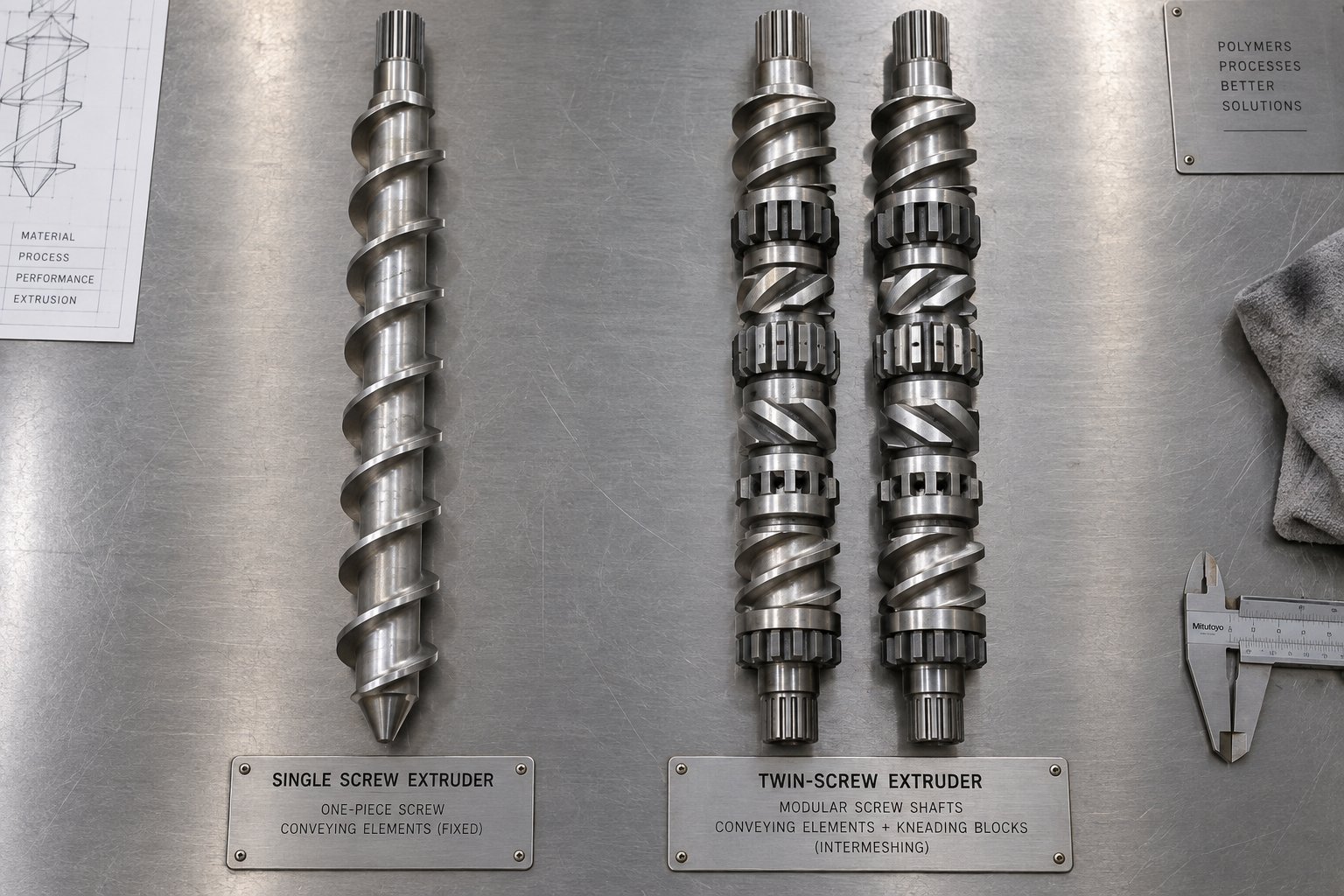
Single-screw replacements are, relatively speaking, the simpler scenario. You're dealing with one screw and one barrel — two primary components with a one-to-one relationship. Most general-purpose single-screw extruders use a solid, one-piece screw design, meaning you specify a single part number, confirm its dimensional and metallurgical details, and install it as a unit.
That simplicity, though, doesn't mean you can treat the project casually. Several design variants raise the specification bar considerably:
- Barrier screws — these use a secondary flight to separate the melt pool from the solid bed. Replacement demands tighter tolerances on the barrier flight clearance than a conventional metering screw, because the gap between the barrier flight tip and the barrel wall controls how melt flows from the solids channel to the melt channel. As industry analysis has documented, barrier flights wear in service just like primary flights, and as the undercut wears, the screw loses melting capacity and efficiency. A replacement barrier screw specified with the wrong clearance — even by a few thousandths of an inch — can underperform from day one.
- Mixing sections — dispersive and distributive mixing elements (Maddock, pineapple, blister ring, etc.) are integral to many single-screw designs. These features rely on precise undercut geometry to generate the shear forces that produce a homogeneous melt. When you're specifying a replacement, every mixing element dimension matters.
- Vented configurations — vented (two-stage) screws require a decompression zone aligned with a barrel vent port. The screw geometry in this zone must match the barrel's vent location exactly, or you'll get either vent flooding (polymer exiting through the vent port) or inadequate devolatilization.
- Grooved-feed sections — some extruders use a grooved feed bushing in the barrel's feed zone to improve solids conveying. The replacement screw's feed-section geometry must be compatible with the grooved liner, which affects channel depth and compression ratio specifications.
Despite these nuances, the core advantage of single-screw replacement is straightforward logistics. One screw, one barrel, a well-defined set of dimensions. Lead times for standard-dimension single screws are typically shorter, and sourcing is more flexible because there's no need to match paired elements or maintain intermesh geometry.
Twin-Screw Extruder Replacement Complexities
Twin-screw systems introduce an entirely different level of complexity. Instead of one monolithic screw, you're often working with a segmented screw configuration — individual elements stacked on splined shafts, each with a specific function (conveying, kneading, mixing, discharge). Replacing segmented twin-screw elements means specifying each element type, pitch, stagger angle, and position along the shaft. A single co-rotating twin-screw extruder can easily contain 30 to 60+ individual screw elements per shaft — and you have two shafts to configure.
Manufacturers like ENTEK produce segmented twin-screw elements ranging from 25 mm to 250 mm in various metallurgies specifically because of this replacement demand. The modularity of segmented designs is actually a double-edged sword: you can replace only the worn elements rather than the entire screw assembly, which reduces cost per replacement event. But you also need to track wear on every individual element, maintain a detailed screw layout diagram, and ensure that replacement elements are dimensionally identical to the originals — or intentionally redesigned with documented changes.
Barrel replacement on twin-screw systems is equally segmented. Most twin-screw extruders use modular barrel sections bolted together in sequence, each with its own heating and cooling zones. Twin screw extruder barrel segment replacement lets you swap only the worn sections — typically the high-shear kneading zones and the discharge end — without pulling the entire barrel assembly. This is a significant advantage over single-screw barrels, which are usually one-piece and must be replaced in full.
The critical geometric challenge unique to twin-screw replacement is intermesh clearance. In co-rotating twin-screw extruders, the two screws mesh together with tight clearances that govern self-wiping behavior, mixing intensity, and conveying efficiency. If replacement screw elements don't maintain the correct intermesh profile — the precise relationship between one element's flight and the other's channel — you risk contact, excessive wear, or even seizure. Counter-rotating twin-screw systems face similar constraints, with the added complexity that many counter-rotating designs use conical screw and barrel geometries.
Conical twin-screw barrel replacement deserves special mention. Unlike parallel twin-screw barrels, which have a constant bore diameter along their length, conical barrels taper from a larger diameter at the feed end to a smaller diameter at the discharge. This geometry makes each barrel a unique, non-interchangeable component. Replacement requires exact replication of the taper angle, bore dimensions at both ends, and the figure-eight bore profile. Stock availability for conical twin-screw components is typically far more limited than for parallel systems, which means longer lead times and higher dependence on the original manufacturer or a supplier with reverse-engineering capability.
How Replacement Scope and Cost Differ
The practical differences between single-screw and twin-screw replacement projects become stark when you lay them side by side. The table below summarizes the key dimensions that shape planning, budgeting, and execution:
| Comparison Dimension | Single-Screw Extruder | Twin-Screw Extruder |
|---|---|---|
| Typical number of components per replacement | 1 screw + 1 barrel (2 primary components) | 30-60+ screw elements per shaft (x2 shafts) + multiple barrel segments |
| Specification complexity | Moderate — one set of dimensions per component, though barrier and vented designs add detail | High — each element type, position, metallurgy, and stagger angle must be individually specified; screw layout diagrams required |
| Partial replacement feasible? | Generally no — screw and barrel are one-piece units replaced in full (barrel liners sometimes replaceable) | Yes — individual screw elements and barrel segments can be replaced independently |
| Intermesh / clearance criticality | Flight-to-barrel clearance only | Flight-to-barrel and screw-to-screw intermesh clearance must both be maintained |
| Lead time considerations | Shorter — standard single screws may ship in days to weeks; custom designs in weeks | Longer — matched element sets and custom barrel segments may require weeks to months, especially for conical configurations |
| Relative component cost | Lower per replacement event — one screw and one barrel | Higher per full replacement — complete twin-screw element sets can range from $20,000 to $100,000+ depending on size and metallurgy; barrel segment sets add further cost |
| Inventory strategy | Keep one complete spare screw per critical line | Keep spare sets of high-wear elements (kneading blocks, discharge elements) plus critical barrel segments; full shaft spares for high-utilization lines |
One important nuance: while twin-screw replacement costs are higher in absolute terms, the modularity of segmented designs can actually reduce cost per replacement event compared to replacing the entire assembly. If you know that your kneading blocks wear three times faster than your conveying elements — a common pattern — you can stockpile just those high-wear elements and swap them at targeted intervals. This precision is unavailable in most single-screw systems, where the entire screw must come out even if only the metering section is worn.
Regardless of which configuration you're working with, the physical process of removing the old components and installing the new ones follows a logical sequence — but the details, safety precautions, and validation steps matter far more than most operators realize.
Step-by-Step Extruder Screw and Barrel Replacement Procedure
You've diagnosed the wear, chosen between repair and replacement, specified the correct components, and accounted for your extruder type. The new parts are on-site and inspected. What happens next is the part that most guides skip entirely — the actual physical process of how to remove an extruder screw and barrel and install the replacements without damaging precision components or creating safety hazards. Getting this sequence right protects equipment worth tens of thousands of dollars and keeps your team safe around hot, heavy machinery.
Pre-Replacement Preparation
Most of the difficulty — and most of the risk — in a screw and barrel swap is decided before anyone picks up a tool. Rushing past preparation is how screws get stuck, flights get bent, and people get burned.
Start with safety lockout/tagout (LOTO). Electrically isolate the extruder drive motor, all barrel heater circuits, and any hydraulic or pneumatic systems connected to the machine. Verify zero energy with a meter, not just a visual check of the breaker panel. This is a hot, heavy job involving burns, crush hazards, and electrical exposure — treat it accordingly.
Before isolating power, though, you need the machine hot and purged. Purging before pulling the screw dramatically improves extraction ease, because residual material is the primary culprit that "glues" a screw into its barrel as temperatures drop. Run the extruder at low RPM with a commercial purge compound until the discharge runs clean, then shut down the drive. Keep barrel heaters energized at or near processing temperature during preparation — you'll lock out only when you're ready to begin physical disassembly.
While the machine is heat-soaking, complete these parallel tasks:
- Disconnect downstream equipment (die, adapter, melt pipe) and move it clear of the work area.
- Rig lifting equipment — an overhead crane, chain hoist, or screw extractor — rated for the screw's weight. Long screws can weigh hundreds of pounds and will bend under their own weight if unsupported during extraction.
- Prepare padded supports (wooden V-blocks or rubber-lined cradles) to receive the screw once it's out. Never set a precision screw on bare concrete or steel.
- Lay out brass scrapers, brass wire brushes, copper gauze, and cotton rags for cleaning. Steel tools are strictly off-limits — they gouge flight surfaces and barrel bores, creating permanent flow disruptions.
- Unbox and visually inspect the replacement screw and barrel. Verify flight OD, overall length, and shank configuration against the specification sheet before you're committed to the swap.
Also disconnect screw-cooling rotary unions and any instrumentation wiring that will interfere with screw withdrawal. If the barrel is also being replaced, tag and photograph every heater band connection, thermocouple wire, and cooling line so reassembly goes back together correctly. These few minutes of documentation save hours of troubleshooting later.
Disassembly Sequence for Screw and Barrel
With preparation complete, the extruder screw removal procedure step by step follows a consistent, logical order. Deviating from this sequence — especially trying to force a cold screw out or skipping the purge — is where most component damage occurs.
- Confirm the machine is purged, hot, and locked out. Material evacuated, barrel still at processing temperature, all energy sources isolated and verified, front end (die, adapter, breaker plate) removed and clear.
- Mark alignment positions. Before disconnecting the screw from the drive, scribe or paint reference marks on the coupling, screw shank, and gearbox output shaft. Record the orientation so reassembly goes back the same way. This step seems minor until you're staring at an unmarked coupling during installation.
- Disconnect the screw from the drive. Unbolt the coupling or disengage the gearbox connection at the screw shank. On splined drive connections, note the key or spline orientation.
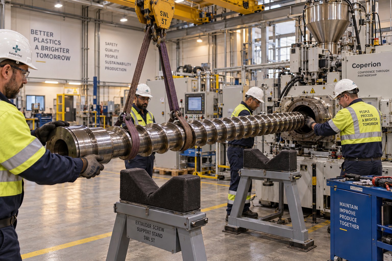
- Push the screw forward from the shank end. Screws are normally pushed out the discharge end, not pulled from the front. Use the machine's built-in screw extractor mechanism or a hydraulic pushing device positioned at the shank end. Apply steady, even pressure — never hammering or impact force. If the screw resists, stop. Re-apply barrel heat evenly with the band heaters, allow time for the residual material to soften, and try again with steady hydraulic pressure. Rotate the screw slowly while pushing if it remains stubborn.
- Support the screw as it emerges. As the first flights exit the barrel, attach the lifting equipment. Continue pushing while supporting the screw's weight to prevent bending or dropping. For long screws, an assistant guiding the emerging end is essential.
- Set the screw on padded supports. Transfer the screw to the prepared V-blocks or cradles immediately. Clean it while still warm using brass tools and copper gauze — resin hardens quickly on cooling surfaces.
- If replacing the barrel: disconnect all heater wiring, thermocouple leads, and cooling lines. Remove the barrel mounting bolts, then use the crane to withdraw the barrel from the machine frame. Barrel removal typically requires sliding the barrel forward or backward depending on the machine design — consult your OEM manual for the correct direction.
One critical warning deserves its own emphasis: never use an acetylene torch on the screw. Localized flame destroys the metallurgical properties of the steel and permanently warps tolerances that are measured in thousandths of an inch. A blowtorch alters the grain structure of the steel, weakening it and making it susceptible to bending and fatigue failure. Even barrel heat — applied slowly and uniformly through the machine's own band heaters — is the only safe thermal approach for a stuck screw.
Installation and Post-Installation Validation
Installation reverses the disassembly sequence, but carries its own set of precision requirements — particularly around extruder screw installation and alignment.
If you're installing a new barrel, slide it into position on the machine frame and bolt it down according to the manufacturer's torque specifications. Before inserting the screw, verify barrel-to-gearbox alignment. The center of the barrel bore at the discharge end must be coincident with the gearbox output shaft axis. Misalignment causes side-loading on the screw, accelerating wear on one side of the barrel bore and reducing component life from the very first revolution. On long-barreled extruders, even small angular misalignment at the gearbox translates to significant offset at the far end. Reconnect all heater bands, thermocouples, and cooling lines using the photos and tags you created during disassembly.
For first-time screw installation into a new barrel, insert the screw at room temperature into a room-temperature barrel. This is a critical check: at ambient temperature, the barrel bore is at its smallest dimension. If the screw slides in smoothly, you've confirmed that both components are within specification. A screw with a manufacturing defect — an oversized OD or a micro-bend — might slide into a thermally expanded hot barrel yet seize as temperatures equalize, potentially destroying both parts. Cold-into-cold eliminates this risk on the first fit. Subsequent installations of the same proven screw can safely go cold-screw-into-hot-barrel.
If the screw doesn't slide in smoothly, stop immediately. Do not force it. Industry experience includes cautionary examples of crews using forklifts to ram screws into position, only to discover binding caused by a burr, a high spot on the shank, or a drive-key tolerance issue — problems that could have been easily corrected with machinist's blue dye and a hand file if caught early. Pull the screw back out, investigate the interference, correct it, and try again.
Once the screw is seated and coupled to the gearbox drive:
- Reconnect and verify all instrumentation. Confirm that every thermocouple reads correctly, every heater zone responds to the controller, and screw-cooling flow is established.
- Perform initial heat-up. Bring the barrel to processing temperature gradually, following the OEM heat-up profile. Allow adequate soak time — typically 30 to 60 minutes after all zones reach setpoint — to ensure thermal equilibrium through the barrel wall and screw.
- Run empty at low speed. Engage the screw drive at minimum RPM with no material feed. Listen for unusual sounds, watch the motor load (amp draw should be minimal), and check for any vibration. Smooth, quiet rotation at low speed confirms proper fit and alignment.
- Introduce material gradually. Start feeding resin at reduced rate and low screw speed. Monitor melt pressure, melt temperature, and motor load as you ramp toward normal operating conditions. Bring the line up incrementally rather than jumping straight to production speed.
Post replacement validation for an extruder screw involves confirming that the new components actually deliver the performance improvement you paid for. The key metrics to track during the first hours and days of operation include:
| Validation Metric | What to Compare Against | What It Confirms |
|---|---|---|
| Specific rate (output per RPM) | Pre-replacement baseline and original OEM data | Conveying efficiency restored; flight clearances correct |
| Melt temperature at constant throughput | Pre-replacement readings and target setpoint | Shear heating normalized; no excessive clearance-driven leakage |
| Melt pressure stability | Pressure variation range before replacement | Consistent metering; no surging from worn geometry |
| Motor load (amps or kW) | Historical data at same RPM and material | Energy efficiency restored; no mechanical binding |
| Extrudate quality (visual and dimensional) | Product specifications and pre-replacement defect rate | Gels, streaks, unmelts, and voids eliminated or reduced |
| Scrap rate | Production records from prior months | Overall process capability recovered |
Document all of these readings as your new baseline. They become the reference point against which you'll track future wear progression — closing the loop on the diagnostic framework from earlier and feeding directly into your next replacement planning cycle.
A successful replacement validates the technical work. But the full payoff depends on how well the project was planned around your production schedule, lead times, and spare parts strategy — factors that separate a smooth, cost-controlled swap from an expensive scramble.
Replacement Planning and Downtime Management
A flawless installation means little if the project itself forced a week of unplanned production loss during your busiest month. The technical steps covered earlier — diagnosis, specification, extraction, validation — all happen within a broader operational context that determines whether the swap feels like a routine maintenance event or an emergency fire drill. Planning extruder downtime for screw replacement is where maintenance discipline meets production reality, and the gap between the two is where money disappears.
Lead Times for Custom vs. Stock Replacement Components
The single biggest variable in your project timeline isn't the physical swap — that typically takes one to three days for a single-screw extruder and two to five days for a twin-screw system. The real schedule driver is how long it takes to get the replacement parts in your hands.
Stock or standard-dimension screws and barrels — common sizes with popular metallurgies — may ship in as few as five to ten business days from suppliers who maintain finished inventory. Custom-engineered components tell a very different story. A bimetallic barrel with a specific alloy liner, a barrier screw with proprietary mixing geometry, or a matched set of twin-screw elements in a specialized carbide grade can require six to twelve weeks of manufacturing time, sometimes longer during periods of high industry demand.
Understanding the extruder screw barrel replacement lead time for your specific components is non-negotiable for realistic planning. The practical implication? By the time physical inspection confirms replacement is needed, you may already be weeks behind on procurement. This is precisely why the wear-monitoring framework from earlier in this article exists — catching progressive wear trends early buys you the lead time your supplier needs to manufacture parts before the situation becomes critical.
Scheduling Replacement During Planned Downtime
The ideal replacement happens inside a window that was already blocked for maintenance, a product changeover, or a seasonal production slowdown. Aligning screw and barrel work with these natural gaps transforms the project economics entirely — you're using downtime that was already "paid for" rather than creating new production losses.
To make this work, estimate total downtime realistically. Factor in the physical replacement procedure itself (one to five days depending on extruder type and scope), plus buffer time for complications — a stuck screw that needs extra heat cycles, a barrel alignment issue, or an instrumentation problem discovered during reassembly. A good rule of thumb is to add 30-50% buffer to your best-case swap estimate. Structured maintenance scheduling that accounts for screw and barrel condition monitoring makes it far easier to slot replacement into the right window rather than scrambling when wear reaches an urgent threshold.
Seasonal patterns deserve attention too. If your facility runs lighter schedules during specific quarters — summer shutdowns, holiday slowdowns, or periods between major customer contracts — those are natural candidates for the longer downtime windows that twin-screw element swaps or full barrel replacements demand. The key is working backward from those windows: if your target replacement date is four months away and lead time for your custom barrel is ten weeks, the order needs to go in within the first few weeks of identifying the need.
Product changeovers offer another underused opportunity. When you're already purging the extruder, disconnecting the die, and resetting process parameters for a new resin, much of the preparation work for a screw swap overlaps. Combining the two events collapses incremental downtime to a fraction of what a standalone replacement would require.
Managing Spare Parts Inventory to Prevent Emergency Stops
Even the best-planned replacement schedule can be blindsided by a catastrophic event — a metal contaminant seizing in the barrel, a broken flight from a foreign object, or accelerated corrosion from a bad resin batch. For high-utilization lines where every hour of unplanned downtime carries significant financial consequences, spare extruder screw inventory management is a strategic insurance policy, not an idle investment sitting on a shelf.
The cost math is straightforward. If your extrusion line generates several thousand dollars per hour in output value, and an emergency component order adds four to eight weeks of lead time on top of the days needed for the physical swap, the production loss dwarfs the carrying cost of a spare screw and critical barrel sections stored on-site. Industry best practices for twin-screw operations specifically recommend establishing a reasonable inventory of wearing parts — screw elements, liners, heaters, and seals — to enable quick replacement and minimize downtime.
Here's how to minimize extruder replacement downtime through a disciplined inventory approach:
- Keep at least one complete spare screw for each critical extruder line — especially lines processing abrasive fillers or corrosive compounds where wear is accelerated and predictable intervals are shorter.
- Stock high-wear twin-screw elements separately — kneading blocks and discharge elements wear far faster than conveying elements. Maintaining targeted spares of just the high-wear items provides fast turnaround without the cost of full duplicate element sets.
- Store spares properly to prevent corrosion — coat exposed metal surfaces with a rust-preventive oil, wrap in VCI (vapor corrosion inhibitor) paper, and store in a climate-controlled area. A spare screw pitted with storage corrosion is a spare screw that can't be used.
- Document every spare's full specification for fast reorder — dimensions, metallurgy, supplier, purchase date, and any design modifications. When a spare goes into service, the reorder should happen the same day, not weeks later when someone notices the shelf is empty.
- Establish relationships with suppliers who can deliver on shortened lead times — knowing which manufacturers maintain semi-finished stock or offer expedited production options can shave weeks off emergency orders.
The investment in spares is modest compared to the exposure it covers. Think of it this way: the cost of one spare screw is a known, fixed, one-time expense. The cost of running without one is an unknown, potentially massive, recurring risk every time a wear event progresses faster than expected or a foreign object incident happens without warning.
Smart planning, realistic lead-time awareness, and disciplined inventory management turn extruder screw and barrel replacement from a reactive scramble into a controlled, predictable maintenance event. Yet even a perfectly timed swap only restores what you had before. The real opportunity — one most maintenance teams overlook entirely — is using the replacement moment to upgrade performance beyond the original baseline.
Turning Replacement Into a Performance Upgrade
Here's a question most maintenance teams never ask: why put back exactly what you had? When a worn screw comes out and a new one goes in, the default instinct is to order a like-for-like duplicate — same geometry, same metallurgy, same design that may have been specified a decade or more ago. That instinct feels safe. It's also a missed opportunity worth real money.
Your extrusion process almost certainly isn't running the same resins, fillers, throughput targets, or quality standards it was when the original screw was designed. Materials evolve. Product specifications tighten. Customer expectations shift. A replacement event is the one moment when upgrading the extruder screw design during replacement costs you almost nothing in additional downtime — the machine is already open, the old screw is already out, and the production window is already scheduled. The only added cost is the engineering thought that goes into specifying something better rather than something identical.
Upgrading Screw Design During Replacement
Think of the original screw as a snapshot of your process requirements at the time the extruder was purchased. If you've since shifted from running neat HDPE to a 20% calcium-carbonate-filled compound, the original general-purpose metering screw is doing a job it was never designed for. If throughput demands have climbed 15% since installation, the original compression ratio and channel depths may be choking the very capacity you need.
Improving extruder output with a screw upgrade during replacement can take several practical forms:
- Adding or improving mixing elements — a Maddock-style dispersive mixer or a spiral distributive mixer added to the metering zone can dramatically improve melt homogeneity, color dispersion, and additive incorporation. Industry case studies document that optimized replacement screws have doubled output in real-world applications — one extruder originally designed for 4.5 tons per shift, which had degraded to 3.5 tons with worn screws, jumped to 8.5 tons after installing a replacement with an optimized design.
- Optimizing compression ratio for current materials — if your resin portfolio has changed, the compression ratio should change with it. A screw designed for rigid PVC granules (compression ratio around 2.5) performs poorly when asked to process LLDPE (which may benefit from ratios above 3.5). Matching the ratio to today's materials improves melting uniformity and reduces the energy wasted fighting an inappropriate geometry.
- Incorporating barrier flight designs — barrier screws separate the solid bed from the melt pool using a secondary flight, producing more consistent melting and higher throughput stability. For processors running polyolefins or other semi-crystalline resins at high rates, a barrier design can meaningfully improve melt quality while reducing discharge temperature variability.
- Adding vented capability for moisture-sensitive resins — if you've transitioned to hygroscopic materials like nylon or PET, a two-stage vented screw design paired with a vented barrel section can eliminate the need for a separate drying system — or at least provide a safety net that prevents splay and hydrolytic degradation. One documented example showed that eliminating one unnecessary vent port (because the replacement location had lower humidity than the original installation site) increased output by 35%.
The principle behind all of these upgrades is the same: screw replacement is a design decision, not just a procurement task. An optimized design tailored to your current application can reduce wear by 50 to 60 percent compared to a generic geometry, because it eliminates the sudden pressure spikes and melt turbulence that cause the most damage. That alone extends the interval before the next replacement, compounding the return on the upgrade investment.
Upgrading Barrel Metallurgy for Extended Service Life
The same logic applies to the barrel — and arguably even more so, because barrel upgrades are almost invisible in terms of added project complexity. You're already pulling the old barrel (or you're ordering a new one to pair with the new screw). The dimensional envelope stays the same. The only variable you're changing is what the bore is made of.
A bimetallic barrel liner upgrade for an extruder is one of the highest-ROI decisions you can make during a replacement event, especially if your original equipment came with a standard nitrided barrel. The numbers tell the story clearly. A nitrided barrel processing 30% glass-fiber-reinforced nylon may last 6 to 8 months before clearances blow past acceptable limits. A bimetallic barrel with a centrifugally cast alloy liner — approximately 1.5 mm thick, with hardness in the 950 to 1,100 HV range — can deliver three to five years in the same application. That's a potential 5x to 8x extension of service life for a component cost increase of roughly two to three times.
The liner material itself should be matched to your dominant wear mechanism:
- Iron-based alloys (Fe-Cr-B) — effective against general abrasion from calcium carbonate, talc, and similar mineral fillers.
- Nickel-based alloys (Ni-Cr-B-W) — designed for corrosive environments like PVC, fluoropolymers, and halogenated flame retardants, where chemical attack weakens the surface ahead of mechanical erosion.
- Tungsten-carbide-bearing alloys — the premium choice for severe abrasive environments, including high-percentage glass fiber compounding, where standard alloys can't keep up with the wear rate.
Importantly, this upgrade doesn't just extend service life — it changes the economics of every subsequent replacement cycle. Fewer replacements mean fewer downtime events, fewer procurement cycles, and a lower total cost of ownership over the extruder's remaining productive life. For lines processing demanding materials, upgrading barrel metallurgy during a scheduled replacement is one of the few maintenance decisions that genuinely pays for itself through avoided future costs.
Working with a Custom Extruder Screw Replacement Supplier
Capturing these upgrade opportunities requires something that a catalog-only supplier can't provide: engineering capability. A like-for-like replacement is a straightforward transaction — you send dimensions, you receive parts. A performance upgrade requires a supplier who can evaluate your application, recommend design modifications, specify appropriate metallurgies, and manufacture components to those custom specifications with the dimensional precision that extrusion demands.
When evaluating potential partners for a replacement project, look for these capabilities:
- Application engineering support — the ability to discuss your resin, filler, throughput targets, and quality requirements and translate those into screw geometry and barrel metallurgy recommendations.
- Custom manufacturing flexibility — not just standard sizes, but the capacity to produce modified compression ratios, barrier flights, mixing elements, and specialized liner alloys.
- Experience across extruder types — single-screw, parallel twin-screw, and conical twin-screw configurations each demand different manufacturing competencies. A supplier fluent in all three reduces your vendor complexity.
- Factory-direct pricing transparency — since the component cost, while not the largest portion of total replacement expense, still matters. Direct-source relationships eliminate middlemen and keep pricing aligned with actual manufacturing costs.
For processors, equipment builders, and maintenance teams looking for this combination of custom engineering and direct-source economics, NANHAIYA is one manufacturer worth evaluating. As a factory-direct supplier of custom and replacement screw barrels for extrusion and injection molding applications, NANHAIYA supports both standard replacements and custom-engineered solutions — the kind of dual capability this section recommends. Their product range covers the full spectrum of configurations that plastics processors encounter, from single-screw extrusion barrels to twin-screw element sets, with the metallurgical options needed to match demanding processing environments.
The broader point holds regardless of which supplier you choose: the moment you open the machine is the moment to think beyond restoration. Every replacement is a chance to upgrade screw design, barrel metallurgy, or both — capturing performance gains that compound over years of production. The real question is whether the economics justify the investment, and that requires a clear-eyed cost-benefit analysis that accounts for far more than just the price of the components themselves.
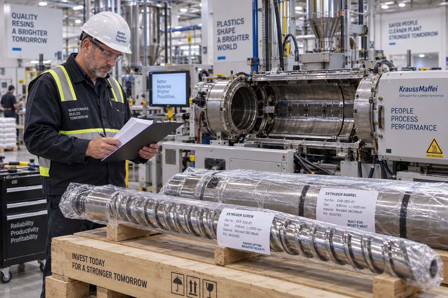
Cost-Benefit Analysis of Screw and Barrel Replacement
Most plant teams can recite the price of a new screw from memory. Far fewer can tell you what a worn screw actually costs them every week it keeps turning. That blind spot — treating the component invoice as the replacement cost rather than one line item in a much larger equation — is what keeps maintenance budgets stuck in a reactive cycle. A rigorous extruder screw and barrel replacement cost analysis flips the conversation from "Can we afford to replace?" to "Can we afford not to?"
Total Cost of Replacement Beyond the Component Price
Imagine you've approved a $12,000 purchase order for a new bimetallic screw. That feels like the cost of replacement. It isn't — not even close. The component itself is often the smallest portion of the total cost of an extruder barrel replacement or screw swap. The real expense is everything that surrounds it.
Here's the full picture, broken into every cost category you need to account for:
- Component cost — the screw, barrel, or both, including any metallurgical upgrades, surface treatments, and quality documentation packages.
- Shipping and expediting premiums — standard freight is modest, but if you're ordering emergency air freight on a 200-pound barrel from overseas, the logistics cost can rival the component cost itself.
- Labor hours for the replacement procedure — skilled maintenance labor for a single-screw swap typically runs 4 to 8 hours; twin-screw systems can demand 16 to 40+ hours depending on scope. At loaded labor rates of $85 to $150 per hour for industrial maintenance technicians in North America, labor alone adds $340 to $6,000+ per event before accounting for supporting crew.
- Production downtime cost — this is the dominant number. A continuous extrusion line producing $1,500 to $5,000 of product per hour loses $12,000 to $40,000 during a single 8-hour maintenance shutdown in lost output value. Twin-screw changeovers stretching across multiple days multiply that figure dramatically.
- Startup scrap and quality losses during run-in — new components need a break-in period. The first hours of production after a swap typically generate off-spec material as the team dials in temperatures, speeds, and pressures. On precision compounding lines, this transition scrap can represent several thousand dollars of wasted resin and additives.
- Peripheral costs — crane rental, tooling, purge compound, replacement heater bands or thermocouples discovered during disassembly, and engineering time spent on specification and validation.
When you add these up, the component price — that $12,000 screw — might represent only 15% to 30% of the total replacement event cost. The rest is dominated by downtime and labor. This realization has a powerful practical implication: minimizing downtime is the primary economic lever, not minimizing component price. Saving $2,000 on a cheaper screw that takes two extra weeks to arrive, forcing an unplanned shutdown during peak demand, is a financial disaster disguised as a procurement win.
Quantifying the Cost of Running Worn Components
The total cost of a replacement event is real and measurable. But here's what makes the business case compelling: the cost of not replacing is almost always higher — it's just harder to see because it accumulates gradually rather than arriving as a single invoice.
Every hour a worn screw and barrel keep turning, they quietly drain profitability through multiple channels:
Increased energy consumption. As flight clearance widens, the screw loses forward-pumping efficiency. Operators compensate by increasing RPM, which raises motor load. Documented studies show a 6% to 12% increase in specific energy consumption (kWh/kg) as screw clearance grows from the original 0.1 mm to just 0.5 mm in a 90 mm single-screw extruder. On a line running 24/7, that energy penalty alone can represent thousands of dollars per month in excess electricity cost — silently inflating your operating budget with no corresponding increase in output.
Reduced throughput. Wider clearances mean more polymer leaks backward over the flights instead of being conveyed forward. You're running the motor harder to produce less. Predictive maintenance data confirms that output at rated RPM dropping below 85% of baseline is a clear signal that wear has crossed into economically damaging territory. That 15%+ throughput deficit, sustained over weeks or months, represents output you simply never produced — revenue that vanished without a purchase order to point to.
Scrap, rework, and additive waste. Inconsistent melt quality from worn geometry produces defects — gels, streaks, voids, and dimensional variation. Some of that material gets scrapped outright. Some gets reworked at additional cost. And as process engineers have documented, operators frequently compensate for worn screws by increasing additive dosages rather than replacing the screw — a Band-Aid that inflates formulation costs (often the largest cost category in compounding) by 20% to 30% while masking the root cause. One real-world case showed that replacing both screws and barrel allowed additive reduction from 1.3% to less than 1%, a 30% savings that paid for the replacement in under a year.
Risk of catastrophic failure. This is the tail risk that makes the entire cost equation asymmetric. A worn screw that seizes, a barrel that develops a stress crack, or a broken flight that damages the bore can turn a planned $30,000 replacement into an unplanned $80,000+ emergency — including expedited parts, overtime labor, lost production, and customer order disruption. The financial difference between a planned screw pull and a catastrophic seizure event can reach $100,000 or more on a single high-output line.
These hidden costs are cumulative and progressive. A screw that's "just a little worn" today will be measurably more worn next month, and each increment of additional clearance accelerates the performance degradation. The cost curve isn't linear — it steepens as wear progresses, because each thousandth of an inch of additional clearance represents a larger percentage increase in leakage flow over the flights.
Making the Business Case for Proactive Replacement
Pulling these threads together creates a decision framework that removes the guesswork from replacement timing and justifies the expenditure in terms any financial stakeholder can understand.
The optimal replacement point is when the cumulative cost of degraded performance — energy waste, lost throughput, scrap, additive overuse, and catastrophic failure risk — exceeds the total cost of a planned replacement event.
In practice, that crossover point arrives far earlier than most teams expect. Consider a quantified example from a 75 mm twin-screw compounding line processing 40% glass-filled PA66: a standard nitrided screw set costing $8,500 lasted roughly 4,000 hours, requiring approximately 6.6 replacement events over a 36-month production horizon. Including downtime at $18,000 per event, labor, and repeat component purchases, the 36-month total cost of ownership reached $182,820. A premium bimetallic screw set costing $34,000 — four times the upfront price — lasted 20,000 hours, requiring only 1.3 replacement events over the same period. Total 36-month cost: $69,160. The "expensive" option delivered a 62% reduction in total operating cost.
That example illustrates two principles that apply across nearly every replacement scenario:
- The cheapest component to buy is almost never the cheapest component to own. Purchase price is one variable in a multi-variable equation where downtime, labor, quality losses, and energy penalties all carry larger weight.
- Proactive, planned replacement during scheduled downtime costs a fraction of reactive, emergency replacement. The physical work is identical. The financial context is completely different.
To justify extruder screw replacement expense to budget decision-makers, present the comparison in total-cost-of-ownership terms over a defined horizon — typically 24 to 36 months. Include every cost category itemized earlier, and contrast the cost of planned replacement against the documented and projected cost of continued operation with worn components. When the numbers are laid out honestly, the replacement almost always pays for itself — often within the first avoided emergency shutdown.
On the component-cost side of the equation specifically, sourcing strategy matters. Factory-direct suppliers who manufacture in-house rather than reselling through distribution layers can meaningfully reduce the per-unit price of screws and barrels without sacrificing quality. NANHAIYA, for example, offers factory-direct pricing on custom and replacement screw barrels for extrusion and injection molding — a sourcing model that compresses the component-cost portion of total replacement expense while still delivering the metallurgical options and dimensional precision that demanding applications require. When every dollar saved on the component is a dollar that improves your overall TCO calculation, the sourcing channel you choose is a legitimate economic lever.
Ultimately, extruder screw and barrel replacement isn't an expense you manage — it's an investment you optimize. The plants that treat it as a structured, data-driven lifecycle event, rather than an unwelcome surprise, consistently spend less over time while running tighter tolerances, higher throughput, and more reliable quality. The components wear out no matter what. How you plan for that reality determines whether the replacement pays for itself or simply costs you twice.
Frequently Asked Questions About Extruder Screw and Barrel Replacement
1. How often should extruder screws and barrels be replaced?
Replacement frequency depends heavily on the materials being processed. Extruders running clean, unfilled polyolefins may go several years between replacements, while lines processing glass-fiber-reinforced compounds or corrosive resins like PVC can wear through components in as few as 6 to 12 months. Rather than relying on fixed schedules, the most reliable approach is tracking specific rate (output per RPM) and measuring flight clearance at regular intervals. When clearance reaches approximately four times the original specification, replacement planning should be underway. Partnering with a factory-direct supplier like NANHAIYA (nhyscrews.com) ensures faster turnaround when the time comes.
2. What are the signs that an extruder screw or barrel is worn out?
The most telling performance indicators include declining throughput at the same screw speed, rising melt temperatures without process changes, inconsistent melt pressure or surging, visible extrudate defects such as gels and streaks, and increasing energy consumption. Physical signs include reduced screw flight outer diameter, enlarged barrel bore diameter beyond tolerance, scoring or galling marks on flight surfaces, corrosion pitting, and hardfacing delamination. When two or more of these symptoms appear simultaneously on a previously stable line, worn plasticating components should be the top suspect in your troubleshooting process.
3. Is it better to repair or replace a worn extruder screw?
The answer depends on wear severity and location. Localized repair through weld-overlay or hard chrome plating makes sense when wear is caught early and confined to one or two zones, with the base metal still structurally sound. However, repaired components typically deliver only 25-50% of original service life. Refurbishment suits moderate, distributed wear and can restore 50-75% of original life. Full replacement is unavoidable when the barrel bore exceeds re-lining limits, screw core diameter drops below engineering minimums, corrosion has compromised the base metal, or the component has already been refurbished once. The most economical choice has the lowest ratio of total cost to expected service life, not the smallest invoice.
4. What information does a supplier need to manufacture a replacement extruder screw or barrel?
A complete specification package should include: machine make, model, and year; screw outer diameter, root diameter, overall length, L/D ratio, flight pitch, compression ratio, and shank configuration; barrel bore diameter, flange dimensions, feed-port geometry, and liner material; the polymer type, filler content, and operating temperatures being processed; required metallurgy or surface treatments such as nitriding or bimetallic liners; and any desired design modifications. If OEM drawings are unavailable, sending a used component sample for reverse engineering via CMM inspection is the next best option. Incomplete specs are the top cause of delays and misfitting parts in replacement projects.
5. How much does extruder screw and barrel replacement cost in total?
The component price, which can range from several thousand to over $100,000 for complete twin-screw element sets, is often only 15-30% of the total replacement cost. The full expense includes shipping and expediting fees, labor at $85-$150 per hour for industrial maintenance crews, production downtime valued at $1,500-$5,000+ per hour of lost output, startup scrap during run-in, and peripheral costs like crane rental and purge compound. This makes downtime minimization the primary economic lever. Factory-direct sourcing from manufacturers like NANHAIYA can reduce the component-cost portion, while proactive scheduling during planned downtime dramatically cuts the overall expense compared to emergency replacement scenarios.
Written by
Nanhaiya Technical Team
Zhoushan Nanhaiya Plastic Machinery Co., Ltd.
The Nanhaiya technical team supports screw and barrel manufacturing projects through application review, technical communication, custom manufacturing coordination, and production and quality control.
Discuss Your Application
Related Articles
More insights on screw barrel technology and plastics processing.
What Your Single Screw Extruder Manufacturer Won't Tell You
Oct 10, 2026
Learn how to evaluate single screw extruder manufacturers with this buyer-focused guide covering specs, configurations, material matching, and a ready-to-use selection checklist.
Read Article
Plastic Extruder Screw Price Demystified: From Steel To Sticker
Oct 10, 2026
What drives plastic extruder screw price? This independent guide breaks down diameter, L/D ratio, metallurgy, order volume, and total cost of ownership factors.
Read Article
What No Supplier Tells You About WPC Decking Making Machines
Oct 6, 2026
Learn how a WPC decking making machine works, compare extruder types, formulations, and production methods, plus get a buyer checklist to evaluate any supplier.
Read ArticleLooking for something else?
Search by material, symptom or product and jump straight to the relevant page.
These are navigation suggestions based on keyword matching — not a quotation, not a delivery commitment, and not a substitute for engineering review. Final specification is confirmed by our engineers against your drawings and processed material.
Need help with screw barrel selection?
Share your machine model, processed material and application. Our team can help with pricing and technical support.