

What Is an Extruder Screw and How Does It Work
Every plastic product you touch — from water bottles to automotive trim — began as raw pellets pushed, squeezed, and melted by a single rotating component. If that component is worn, poorly designed, or mismatched to your material, you're bleeding output without realizing it.
Defining the Extruder Screw and Its Function
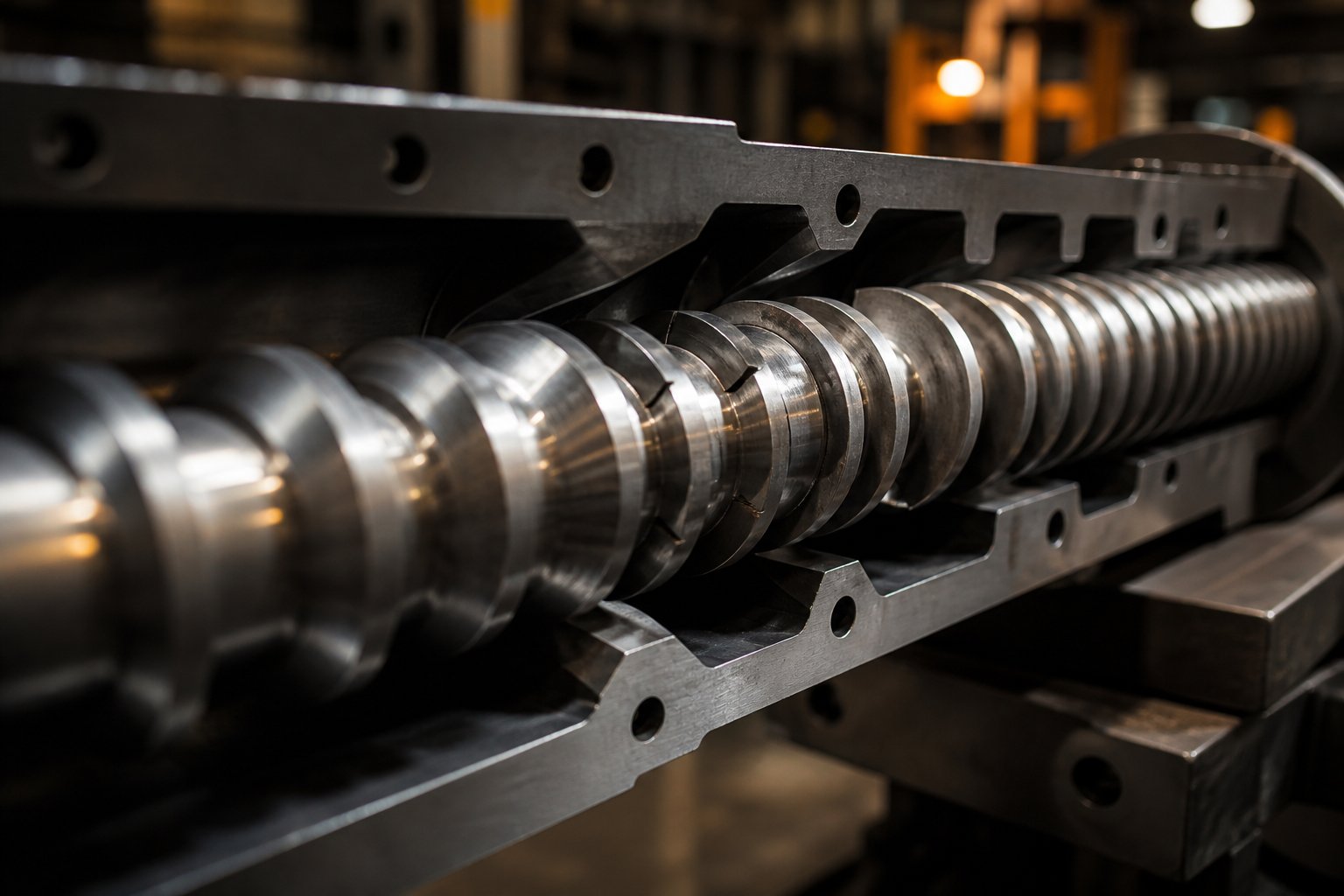
An extruder screw is a helical, precision-machined rotating shaft housed inside a heated barrel that conveys, compresses, melts, and homogenizes polymer material, then forces the resulting melt through a die to form a continuous profile.
Think of it as the engine of any extrusion line. The screw's rotation creates two competing forces that together determine how much material exits the die. Drag flow is the forward movement generated by friction between the rotating screw and the stationary barrel wall — imagine pulling taffy by rolling it between your hands. Pressure flow works in the opposite direction, driven by resistance at the die end, pushing melt back toward the feed. The net output of a screw extruder is always the balance between these two flows, and every geometric decision in screw design shifts that balance.
The Three Functional Zones of an Extruder Screw
A standard extrusion screw divides its length into three distinct zones, each with a specific job:
- Feed zone: The deepest channel section, where solid pellets or powder enter from the hopper. Constant flight depth here allows the screw to grab and convey material forward while trapping air between particles.
- Transition (compression) zone: The channel gradually becomes shallower, compressing the material. This shrinking space builds pressure that prevents air from traveling downstream and generates frictional heat that begins melting the polymer.
- Metering zone: A shallow, constant-depth section where the plastic is nearly fully molten. This zone mixes the melt to thermal uniformity and pumps it at a steady rate toward the die.
The ratio of each zone's length, combined with the depth change from feed to metering, is what gives every extrusion screw its processing character. Get those proportions wrong for your resin, and you'll fight surging, unmelts, or degradation on every run.
From Desktop to Industrial Scale
Here's what surprises many newcomers: these same three-zone principles govern screws across the entire scale spectrum. A hobbyist running a filabot filament extruder to recycle plastic into 3D-printing filament relies on the same drag-flow-versus-pressure-flow physics as an operator managing a 6-inch production line. Even compact systems like the filabot ex2 use a carefully proportioned screw with feed, compression, and metering sections — just miniaturized. The diameter changes, the motor shrinks, but the underlying design logic stays identical.
That universality is precisely why understanding screw geometry matters so much. Whether you're scaling up from a benchtop unit or troubleshooting a high-volume line, the parameters that control melt quality and throughput are the same — and when they're off, the symptoms show up in identical ways. The question, then, is which geometric variables you should be watching and how they interact.
Extruder Screw Geometry Parameters Explained
Knowing that three zones exist is one thing. Knowing the exact dimensions that define those zones — and how changing one dimension ripples through everything else — is where real process control begins. Every extruder screw is governed by a handful of geometric parameters, and each one pulls a specific lever on melt quality, throughput, and energy consumption.
Key Geometric Parameters Every Engineer Should Know
Imagine unwinding the helical channel of an extruder screw and laying it flat. You'd see a long, shallow trough defined by a series of measurable features: how deep the trough is, how wide, how steeply it spirals, and how long it stretches relative to the screw's diameter. These measurements — individually simple — interact in complex ways once the screw is spinning inside an extruder screw barrel under heat and pressure.
The table below consolidates every critical parameter, its definition, the range you'll typically encounter, and the performance lever it controls. Bookmark it — you'll reference it often.
| Parameter | Definition | Typical Range | Primary Effect on Performance |
|---|---|---|---|
| L/D Ratio | Ratio of the screw's functional length to its outer diameter | 20:1 to 36:1 | Residence time, mixing quality, melt homogeneity |
| Compression Ratio | Feed zone channel depth divided by metering zone channel depth | 1.5:1 to 4.5:1 | Melt densification, shear intensity, plasticization quality |
| Helix Angle | Angle between the screw flight and a plane perpendicular to the screw axis | 15° to 30° | Forward conveying rate, shear input, volumetric output |
| Feed Zone Flight Depth | Distance from flight tip to root diameter in the feed section | 0.10D to 0.15D | Solids intake capacity, conveying volume |
| Metering Zone Flight Depth | Distance from flight tip to root diameter in the metering section | 0.03D to 0.07D | Shear rate in the melt, pumping stability |
| Flight Width | Thickness of the screw flight measured along the screw axis | ~0.1D | Leakage flow over flights, structural strength |
| Channel Width | Open space between adjacent flights, measured perpendicular to the flight | Varies with pitch | Material volume per turn, mixing opportunity |
| Pitch | Axial distance between corresponding points on adjacent flights | Often equal to D (square pitch) | Conveying speed, helix angle, output per revolution |
| Root Diameter | Diameter of the screw body at the base of the channels | Increases from feed to metering | Channel depth (and therefore compression ratio) |
How L/D Ratio and Compression Ratio Shape Performance
Of all the numbers on that table, two dominate almost every design conversation: L/D ratio and compression ratio.
L/D ratio controls how long the polymer stays inside the barrel. A longer screw — say 30:1 instead of 24:1 — gives the material more time to absorb heat, mix uniformly, and develop a stable melt. That extra residence time is invaluable for hard-to-melt resins or formulations loaded with additives. The trade-off? Higher power consumption, tighter manufacturing tolerances, and increased risk of shaft deflection on smaller-diameter extruder screws. For thermally sensitive polymers like PVC, a shorter L/D ratio is often deliberately chosen to minimize heat exposure and prevent degradation.
Compression ratio determines how aggressively the screw squeezes material as it moves from the deep feed channel to the shallow metering channel. A higher compression ratio facilitates thorough plasticization and densification — essential for polyolefins that arrive as low-bulk-density pellets. Drop it too low for those materials, and you'll see unmelts in your extrudate. Crank it too high for a shear-sensitive resin like rigid PVC, and frictional heat will degrade the polymer before it ever reaches the die. The sweet spot is always material-dependent, which is why a single extruder screw designed for polyethylene can cause quality disasters when someone bolts it in to run nylon.
These two parameters are also deeply linked. Increasing the L/D ratio at a fixed compression ratio spreads the compression more gradually across a longer transition zone, reducing the shear spike at any single point. Conversely, a short screw with a high compression ratio creates an abrupt squeeze that can generate excessive localized shear and heat.
Flight Depth, Channel Width, and Their Effect on Output
Flight depth is the silent throughput governor. In the feed section, a deep groove enhances the screw's ability to convey material — more volume per revolution means more polymer moving forward. But there's a structural ceiling: excessively deep channels weaken the screw root, raising the risk of shear failure under high torque. They also make it harder to distribute heat evenly across all the material in the channel, leading to pockets of under-processed resin.
In the metering zone, shallow channels serve a different purpose entirely. The thin melt layer between the root and barrel wall experiences high shear rates, which promotes heat transfer, mixing, and a uniform melt temperature. Reduce that depth too far, though, and you choke output — the screw simply can't push enough volume through to the die.
Channel width plays a complementary role. Widening the channel (by narrowing the flight) increases the volume available for material and, as a bonus, reduces rotational friction, lowering power consumption. The cost is a thinner flight that wears faster and permits more leakage flow over the flight tip — that small stream of melt that slips backward between the flight crest and barrel wall without being pushed forward.
Here's the conceptual takeaway that ties everything together: throughput from any screw is ultimately the product of channel geometry, rotational speed, and material viscosity. A wider, deeper channel spun faster moves more material, but it also changes shear rates and residence time. A high-viscosity resin resists flow, amplifying pressure buildup and shifting the drag-flow-versus-pressure-flow balance discussed earlier. No single parameter operates in isolation — adjusting one always nudges several others, which is exactly why swapping extruder screws without recalculating the full geometric picture so often leads to unexpected output losses.
Geometry, however, is only half the story. The same screw design performs very differently depending on whether it's working alone inside a single barrel or alongside a partner in a twin-screw configuration — a distinction that reshapes mixing capability, shear generation, and application fit from the ground up.
Single-Screw vs Twin-Screw Extruder Comparison
A single screw spinning inside a barrel can do remarkable work — but it can't do every job. Some processes demand mixing intensity, modular flexibility, or independent speed-versus-output control that a lone screw simply can't deliver. Understanding where each configuration excels (and where it falls short) prevents the costly mistake of forcing the wrong machine into the wrong application.
Single-Screw Extruders and Where They Excel
Single-screw extruders remain the workhorses of profile extrusion, pipe production, film blowing, and sheet lines. Why? They're mechanically straightforward — one screw, one barrel, minimal alignment concerns — which translates to lower upfront cost, simpler maintenance, and decades of well-understood process behavior. For pumping a consistent, pre-compounded resin through a die at steady rates, a well-designed single screw is hard to beat.
These machines have also evolved far beyond the simple constant-pitch designs of the 1930s. Modern single-screw extruders routinely incorporate barrier screw geometries, grooved feed sections, and specialized mixing heads that dramatically improve melting efficiency and output uniformity compared to their ancestors. That evolution keeps used single screw extruders highly relevant on the secondary market — a well-maintained machine with an upgraded screw design can outperform a newer unit running a basic general-purpose geometry.
The limitation? Single-screw machines rely on drag flow for conveying, which means output and screw speed are tightly coupled. They also lack the self-wiping capability needed for rapid material or color changes, and their distributive mixing ability is inherently limited unless dedicated mixing sections are added.
Twin-Screw Co-Rotating vs Counter-Rotating Configurations
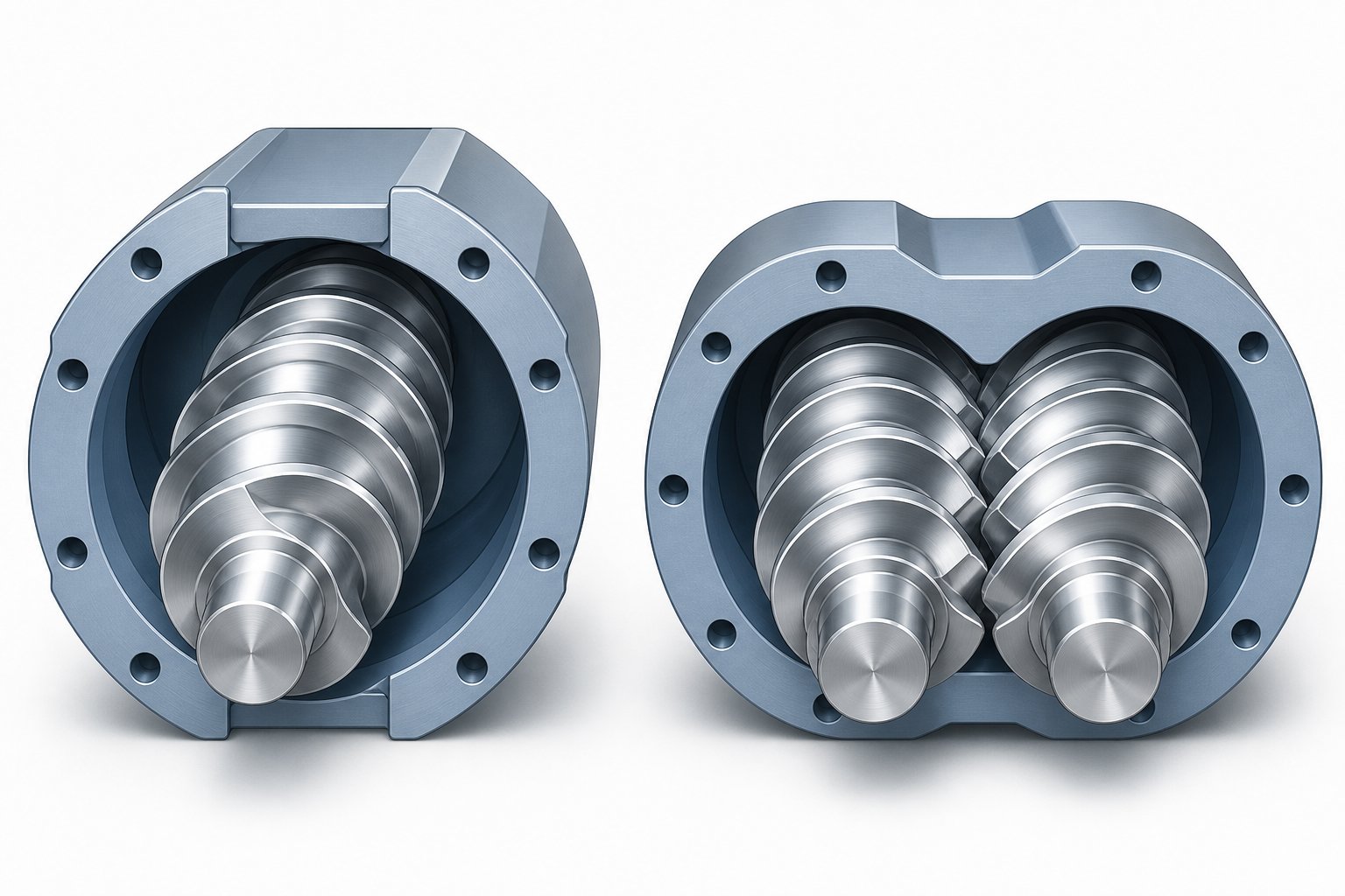
Twin-screw extruders place two screws inside the same twin screw barrel, and the direction those screws turn changes everything about how material behaves between them.
Co-rotating twin screws spin in the same direction. At the intermeshing zone, one screw pulls material into the gap while the other pushes it out, creating a figure-eight material path and extremely high shear at the nip point. This gives co-rotating designs excellent self-cleaning behavior — material doesn't stagnate on the screws, so heat-sensitive polymers avoid localized degradation. They use metered starve feeding, which decouples throughput from screw speed and makes process optimization far more flexible. That's precisely why co-rotating configurations dominate compounding, reactive extrusion, and devolatilization.
Counter-rotating twin screws turn in opposite directions, creating a calendering action that generates high pressure with comparatively lower shear. This gentler approach makes them ideal for processing shear-sensitive materials — rigid PVC pipe and profile extrusion is the classic example. The intermeshing counter-rotating design excels at pressure buildup and positive displacement conveying, but at lower maximum speeds than co-rotating machines.
A defining advantage of both twin-screw types is their modular screw and barrel architecture. Rather than a single monolithic shaft, a twin screw and barrel system is assembled from interchangeable conveying elements, kneading blocks, and mixing discs on a splined shaft. Engineers can rearrange these building blocks to fine-tune shear intensity, residence time, and venting locations for each specific formulation — a level of customization that monolithic single-screw designs can't match without fabricating an entirely new screw.
Choosing the Right Screw Type for Your Application
The table below compares all three configurations across the six dimensions that matter most when selecting equipment — whether you're specifying a new line or evaluating a used twin screw extruder on the secondary market.
| Dimension | Single-Screw | Co-Rotating Twin-Screw | Counter-Rotating Twin-Screw |
|---|---|---|---|
| Mixing Capability | Moderate — relies on added mixing sections for distributive/dispersive mixing | Excellent — interchangeable kneading blocks provide precise control of both mixing types | Good — effective distributive mixing with lower dispersive intensity |
| Throughput Capacity | High for pumping pre-compounded resin; output tied to screw speed | High — throughput set independently via feeder rate, not screw RPM | Moderate — limited by lower permissible screw speeds |
| Shear Generation | Low to moderate — adjustable with barrier or mixing screw designs | High — opposing velocity vectors at mesh zone create intense shear | Low to moderate — calendering action limits peak shear |
| Equipment Cost | Lowest — simpler drive, bearings, and barrel design | Highest — complex gearbox, segmented screws, precision barrel alignment | Moderate to high — simpler than co-rotating but more complex than single-screw |
| Maintenance Complexity | Low — fewer wear components, straightforward screw removal | Higher — modular elements require periodic inspection and reassembly; gearbox servicing | Moderate — less element reconfiguration than co-rotating, but dual-screw alignment needed |
| Typical Applications | Film blowing, pipe extrusion, profile extrusion, sheet lines | Compounding, masterbatch, reactive extrusion, devolatilization, recycling | PVC pipe and profile, low-shear compounding, specialty extrusion |
Notice the pattern: single-screw machines win on cost and simplicity when the job is steady-state pumping of a uniform melt. Co-rotating twins win when you need to blend, react, or devolatilize — tasks that require intense, controllable mixing and independent throughput adjustment. Counter-rotating twins carve out a niche where gentle shear and high pressure matter more than mixing intensity.
Selecting the right configuration, however, is only the first decision. Even the ideal screw type underperforms if it operates in isolation from the rest of the extrusion system — the barrel heating zones, the feed throat, the screen pack, and the die all shape how that screw actually behaves under real production conditions.
How the Extruder Screw Fits Into the Complete Extrusion System
An extruder screw never works alone. It spins inside a barrel surrounded by heater bands and cooling fans, receives pellets through a feed throat shaped to prevent bridging, and pushes melt through a screen pack and die that resist its forward push. Change any one of these surrounding components and the screw's output, melt quality, and energy consumption shift — sometimes dramatically. Treating the screw in isolation is one of the most common reasons processors chase the wrong fix when output drops or defects appear.
Screw and Barrel Interaction in the Melt Process
The extruder barrel is divided into multiple independently controlled heating and cooling zones — typically three to five along its length. Each zone's temperature setpoint works with the screw geometry in that region to control how fast the polymer melts and how uniform the resulting melt becomes.
Here's what catches most operators off guard: in a properly running barrel extruder at production speed, the heater bands in the compression and metering zones are frequently off. The polymer generates so much frictional heat from being dragged and sheared against the barrel wall that cooling fans or water jackets kick in to remove excess energy. As industry training resources note, the heaters do the heavy lifting during startup, but once the system reaches equilibrium they often spend more time cooling than heating.
This means the barrel temperature profile is not simply dictating melt temperature — it's moderating the shear heat the screw generates. Set the rear zones too high, and pellets soften prematurely before the screw can grip them. Set the front zones too low, and the melt viscosity rises, spiking back pressure and robbing output. The screw barrel pairing must be tuned as a unit: geometry determines shear input, and the temperature profile determines how much of that shear energy stays in the polymer versus gets rejected to the surroundings.
Precision matters here more than many operators realize. Even slight temperature fluctuations across the extruder barrel can produce inconsistent melt viscosity, die buildup, or reduced product strength. That's why production-grade machines use closed-loop heating systems with ceramic band heaters and calibrated thermocouples on every zone to maintain stability within a few degrees.
Feed Throat Design and Its Impact on Screw Performance
Before the screw can compress, melt, or meter anything, it has to grab pellets — and the feed throat is where that handoff happens. This short, water-cooled section connecting the hopper to the barrel is easy to overlook but surprisingly powerful in its influence on overall output.
The extruder feed barrel throat is deliberately kept cool for a counterintuitive reason: if the throat overheats, pellets soften on the wall, stick together, and form an arch that starves the screw downstream. Operators sometimes blame surging on screw design when the real cause is a feed throat running just 10 degrees too hot. Consistent cooling at the throat ensures pellets drop freely and pack into a dense solid plug within the first few screw flights.
Grooved feed sections take this concept further. By machining axial grooves into the feed bore — typically 8 to 18 evenly spaced grooves on a 3.5-inch machine — the barrel wall grips pellets more aggressively. With many polymers, grooved-feed extruders produce 20 to 40 percent higher output per RPM than the same diameter machine with a smooth feed bore, because the enhanced solids conveying reduces the energy put into the polymer and lowers melt temperature. The grooves are intensively water-cooled to prevent resin from melting inside them, and screws paired with grooved feeds use shallower channels — roughly half the depth of smooth-bore screws — to maintain high forward force and consistent compression entering the heated barrel.
The trade-off is flexibility. Smooth-feed extruders handle a wider variety of polymers and regrind particle sizes without adjustment. Grooved feeds perform best on dedicated lines running one or two polyolefins at high rates, where the output and energy benefits justify the narrower processing window.
Breaker Plates, Screen Packs, and Die Resistance
Everything the screw builds — pressure, melt uniformity, forward momentum — encounters resistance at the barrel's discharge end. That resistance comes from two components sitting between the screw tip and the die: the breaker plate and the screen pack.
The breaker plate is a thick steel disc drilled with dozens of holes. The screen pack — usually a stack of wire-mesh filters layered coarse-fine-fine-coarse — sits just upstream. Together, they perform three critical functions:
- Filtration: Charred polymer, pellet fines, and occasional metal fragments get trapped before they reach the die and ruin the product surface.
- Flow conversion: Melt leaving the screw carries a strong rotational velocity component from the helical channel. The breaker plate's straight holes convert that spiral motion into parallel axial flow, which the die requires for uniform profile dimensions.
- Back pressure generation: This is the function most operators underestimate. The resistance created by the screen pack and breaker plate forces the screw to push harder, which improves melting and mixing in the compression and metering sections. A clean line with no screen pack often produces under-melted, poorly mixed output — the screw simply doesn't encounter enough resistance to do its job properly.
Screen mesh selection is a direct trade-off: finer mesh catches smaller contaminants but raises the pressure drop, generates more heat at the screen, and clogs faster. Most production runs start at a moderate mesh and schedule changes when head pressure climbs roughly 30 percent above its clean baseline.
The die itself adds the final layer of resistance. As the melt squeezes through narrowing die channels, viscous resistance generates additional shear heat and fights against the screw's forward push. This back pressure directly affects the drag-flow-versus-pressure-flow balance in the metering zone discussed earlier. Increase die resistance — by switching to a finer screen, a more restrictive die geometry, or a cooler die temperature — and pressure flow (the backward leakage) increases relative to drag flow, reducing net output at a given screw speed. Decrease it, and the screw pushes more volume forward but with less mixing and potentially incomplete melting.
Screw speed adds another layer. Increasing RPM raises both drag flow and shear rate, boosting output but also increasing residence-time variability and shear heating. In smooth-bore machines, higher screw speed also demands higher die pressure to maintain melt quality, creating a feedback loop where energy consumption climbs faster than output. Grooved-feed systems partially decouple this relationship because solids conveying is governed by groove geometry rather than friction alone — but even there, limits exist.
The takeaway is straightforward: every component surrounding the screw — from the cooled feed throat to the heated barrel zones to the screen pack and die — forms a coupled system. Changing any single element shifts the operating point of the entire line. An extruder screw that delivers perfect melt quality at one set of system conditions can produce surging, unmelts, or degradation when paired with a different screen pack density, a misaligned barrel temperature profile, or a restrictive die. Diagnosing output problems starts not with the screw alone, but with understanding where the system balance has shifted — and that understanding becomes especially critical when different polymer families demand fundamentally different screw geometries and system setpoints.
Matching Extruder Screw Design to Polymer Type
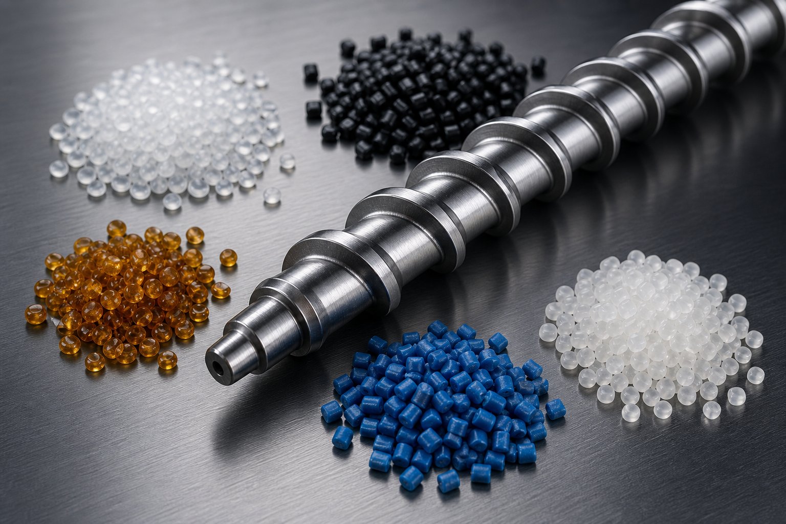
A plastic extruder screw designed for polyethylene will wreck a PVC run. A screw that handles nylon beautifully will choke on polystyrene. This isn't intuition — it's physics. Every polymer family melts differently, tolerates different shear levels, and arrives at the feed throat in a different physical form. Ignoring those differences when specifying a plastic extrusion screw is the single fastest way to sabotage output and quality on an otherwise capable line.
Why Different Polymers Demand Different Screw Designs
The root of the problem lies in two material properties that vary enormously across polymer families: melting behavior and shear sensitivity.
Semi-crystalline polymers — polyethylene (PE), polypropylene (PP), polyamide (PA), and PET — have a sharp melting point. They exist as hard solids one moment and transition to a fluid melt over a narrow temperature range. Processing these resins requires enough compressive energy to push through that phase change quickly and completely. A screw plastic extruder running HDPE, for example, needs a relatively high compression ratio to densify the low-bulk-density pellets and deliver enough shear heat to drive the crystalline phase transition. Fall short on compression, and you'll find unmelted pellets embedded in your extrudate.
Amorphous polymers — polystyrene (PS), ABS, polycarbonate (PC) — behave differently. They soften gradually over a broad temperature range with no distinct melting point. This progressive softening means they're generally more forgiving of moderate compression ratios but can overheat quickly if shear gets too aggressive, since they lack the latent heat "sink" that crystalline melting provides.
Then there's PVC, a category unto itself. Rigid PVC is extraordinarily shear-sensitive — excessive frictional heat triggers rapid thermal degradation, releasing hydrochloric acid that corrodes the extrusion barrel and contaminates the product. That's why rigid PVC screws use deliberately low compression ratios and shorter L/D ratios: the goal is to melt the material gently, with minimal residence time, before degradation chemistry can gain a foothold. The form of the feedstock matters too. PVC powder has lower bulk density than PVC granules, which shifts the ideal compression ratio upward to account for the additional trapped air that must be expelled during plasticization.
Compression Ratio Selection for Common Plastics
The table below maps major polymer families to recommended screw parameters. Use it as a starting framework — actual specifications should always account for your specific feedstock form, additive package, and downstream equipment.
| Polymer Family | Compression Ratio | Typical L/D Range | Screw Design Notes |
|---|---|---|---|
| PE (HDPE/LDPE) | 3:1 to 4:1 | 24:1 to 30:1 | High compression needed for low-bulk-density pellets; barrier screw designs improve melting consistency |
| PP | 2.5:1 to 4:1 | 24:1 to 30:1 | Similar to PE; slightly broader range depending on melt flow index and additive loading |
| Rigid PVC (granules) | 2:1 to 3:1 | 20:1 to 24:1 | Low compression, short residence time to prevent degradation; corrosion-resistant barrel and screw materials essential |
| Rigid PVC (powder) | 3:1 to 4:1 | 20:1 to 24:1 | Higher compression than granules to expel trapped air from powder; still requires gentle shear profile |
| PS | 2:1 to 4:1 | 24:1 to 30:1 | Amorphous — softens gradually; moderate compression sufficient; overheating risk at high RPM |
| ABS | 1.6:1 to 2.5:1 | 24:1 to 30:1 | Low to moderate compression; shear sensitivity increases with rubber content |
| PA (Nylon 6, 66) | 3:1 to 3.7:1 | 24:1 to 30:1 | High compression for sharp crystalline melt point; vented/two-stage screw recommended for moisture removal |
| PET | 3:1 to 3.7:1 | 24:1 to 30:1 | Hygroscopic — requires thorough pre-drying or vented screw; barrier designs improve melt uniformity |
| Recycled Blends / PCR | 2.5:1 to 3.5:1 | 28:1 to 36:1 | Variable bulk density and contamination; two-stage vented screw strongly recommended for devolatilization |
Notice the wide range for some polymers — that isn't vagueness. A PP homopolymer pellet with a narrow molecular weight distribution and a PP random copolymer powder loaded with 40% calcium carbonate filler are both "PP," but they need meaningfully different screw geometries. The compression ratio values in this table reflect well-established industry guidelines for common forms of each resin, but your specific formulation and feedstock form should always drive the final specification.
Screw Geometry for Shear-Sensitive and Recycled Materials
Two categories of materials deserve special attention because they're increasingly common on production floors and almost universally underserved by generic screw designs: shear-sensitive polymers and recycled plastics.
Shear-sensitive resins — rigid PVC, certain medical-grade TPUs, and PVDF, among others — degrade not from excessive temperature alone but from the combination of heat and mechanical shear history. For these materials, the screw must deliver just enough energy to plasticize without crossing the degradation threshold. Practically, that means lower compression ratios (often below 2.5:1), reduced L/D ratios to minimize residence time, and sometimes variable-pitch screw designs that spread compression more gradually than variable-depth designs. Counter-rotating twin-screw extruders are frequently the right choice here, since their calendering action develops pressure with relatively gentle shear.
Recycled and post-consumer resin (PCR) introduces a completely different challenge: volatile contamination. Recycled pellets carry residual moisture, printing inks, adhesive residues, and trace organic compounds from their previous life as consumer packaging. Feed them through a standard single-stage screw, and those volatiles produce bubbles, surface defects, and noxious off-gassing at the die.
This is where vented and two-stage screw designs become essential — a topic that's conspicuously absent from most extrusion guides despite its growing practical importance.
A two-stage screw divides the extrusion process into two sequential melt-and-pump cycles separated by a decompression zone. In the first stage, polymer melts and builds pressure just like a standard screw. The melt then enters a sudden deep-channel decompression zone where the channel volume expands dramatically, dropping pressure to near atmospheric levels. At this decompression point, a vent port in the extrusion barrel — often connected to a vacuum pump pulling 15 to 25 inches of mercury — allows trapped moisture, volatiles, and decomposition gases to escape from the exposed melt surface. The second stage then recompresses and meters the now-devolatilized melt toward the die.
The engineering challenge, as extrusion expert Jim Frankland explains, is balancing the output between stages. The second stage must convey more polymer than the first stage delivers — otherwise, melt floods the vent port and devolatilization stops entirely. Since both stages share a single shaft rotating at the same speed, designers achieve this balance by making the second-stage flights deeper, increasing drag flow capacity. But deeper channels also amplify sensitivity to head pressure: pressure flow scales with the cube of channel depth, so even moderate changes in downstream resistance from screen packs or die geometry can throw the stage balance off and cause vent flooding.
When does a two-stage vented screw make more sense than simply pre-drying the resin? Consider these scenarios:
- Post-consumer recycled streams with variable and unpredictable contamination levels — pre-drying removes moisture but not printing inks, adhesive residues, or low-molecular-weight decomposition products.
- Hygroscopic engineering resins like PA and PET being processed in high-humidity environments where maintaining dew-point-controlled drying consistently is impractical or cost-prohibitive.
- Regrind-heavy operations where multiple heat histories have generated volatile degradation byproducts that only vacuum extraction can remove.
For processors running significant volumes of PCR — and that number is growing rapidly as the industry moves toward a circular economy — converting to a vented extruder is often not optional. The additional melt filtration these applications demand further raises head pressure, which makes accurate second-stage design even more critical. Getting this balance wrong doesn't just waste material at the vent port; it produces exactly the kind of volatile-contaminated, bubble-riddled extrudate the system was supposed to eliminate.
Matching screw design to polymer type is ultimately about respecting what each material needs: the right compression for its melting behavior, the right shear for its degradation threshold, and the right venting for its volatile profile. But even a perfectly matched screw geometry delivers inconsistent results if the melt isn't properly mixed — and mixing, it turns out, comes in two fundamentally different varieties that demand very different screw section designs.
Mixing Elements and Specialized Screw Sections
Those two varieties — distributive and dispersive — aren't interchangeable, and confusing them is one of the most common reasons color streaks, filler clumps, and additive inconsistency persist even after operators have exhausted every temperature and speed adjustment on the control panel. A general-purpose screw has minimal built-in mixing capability. When the process demands more, the answer isn't cranking up the RPM — it's adding the right mixing section to the screw design.
Distributive vs Dispersive Mixing Principles
Imagine dumping a handful of sand into a bucket of wet concrete. You need two things to happen: the sand clumps need to break apart into individual grains (that's dispersive mixing), and those grains need to spread evenly throughout the entire bucket (that's distributive mixing). In screw extrusion, the same two tasks apply to colorants, fillers, stabilizers, and blowing agents — but each task requires a fundamentally different mechanical action.
Dispersive mixing applies intense shear stress to break down agglomerates — clumps of pigment particles, undispersed filler bundles, or gels of partially crosslinked polymer. The melt is forced through a narrow gap or over a restrictive barrier, and the high shear in that gap tears agglomerates apart. Think of it as a brute-force operation: high energy, concentrated on a small volume of material at a time.
Distributive mixing takes a different approach. Instead of applying intense force, it repeatedly splits, reorients, and recombines the melt stream so that every minor component gets spread uniformly throughout the bulk. No extreme shear is needed — just a geometry that divides the flow into many sub-streams and reassembles them in new arrangements. As NC State Extension research explains, distributive mixing evenly spreads the dispersed phase without breaking down particles, while dispersive mixing breaks down clumps by applying strong shear stress.
Why does this distinction matter so much in practice? Because choosing the wrong type causes new problems. A dispersive mixer on a shear-sensitive PVC compound generates localized overheating and degradation. A distributive mixer asked to break up tightly bonded pigment agglomerates simply shuffles the clumps around without splitting them — you get an evenly distributed pattern of streaks instead of a uniform color.
Single-Screw Mixing Elements and Their Applications
Twin-screw extruders get most of the attention when mixing is discussed, thanks to their modular kneading blocks and screw-element libraries. But single-screw machines — which still dominate film, pipe, profile, and sheet production — also have a rich toolkit of mixing sections that can be integrated into the screw and barrel system. The challenge unique to single-screw designs, as extrusion authority Jim Frankland notes in Plastics Technology, is that all shearing force originates from the barrel wall. Shear stress is highest at the barrel surface and drops to nearly zero at the screw root. Any effective mixer must therefore "turn the melt over" — forcing material from the bottom of the channel to the top — so the entire melt volume sees comparable shear history.
Here are the four most important single-screw mixing element types, each with a distinct geometry and mixing character:
- Maddock (Fluted) Mixer: Also called the Union Carbide or LeRoy mixer. This section features alternating in-flow and out-flow flutes separated by a barrier rib. Polymer enters one set of flutes, is forced over the narrow barrier clearance under high shear, and exits through the adjacent flutes. The barrier rib ensures every bit of melt passes through the high-shear gap, making the Maddock an excellent dispersive mixer. It excels at breaking up pigment agglomerates, destroying gels, and serving as a final melting check — nothing unmelted can cross the barrier. Best for polyolefin film lines with masterbatch letdown, or any application where hard agglomerates must be eliminated.
- Pin Mixing Section: Rows of cylindrical pins protrude from the screw root into the melt channel. As the screw rotates, these pins repeatedly divide the melt stream into sub-streams that recombine downstream. Pins are primarily distributive mixers — they spread additives evenly with relatively low additional shear. Because they generate minimal extra heat, pin mixers are the go-to choice for shear-sensitive materials like rigid PVC or thermally unstable formulations where a Maddock would risk degradation.
- Pineapple Mixer: Named for its surface pattern, this element features a diamond or cross-hatched array of intersecting slots cut into a cylindrical section. Melt flows through these crisscrossing channels, splitting and recombining in multiple planes. The pineapple mixer delivers moderate shear — stronger than pin mixing but gentler than a Maddock — placing it squarely in the distributive-with-moderate-dispersive category. It's a versatile middle-ground option for general-purpose blending where both some agglomerate reduction and good spatial uniformity are needed.
- Dulmage Mixing Head: This design uses a series of slotted ring sections arranged in groups along the screw tip, with alternating offset slots that force the melt to change direction repeatedly. Each ring divides the flow, and the offset arrangement recombines sub-streams from different radial positions. Dulmage heads provide distributive mixing through repeated flow splitting. However, as Frankland observes, designs like the Dulmage that apply all shearing force from the same side without rolling the melt over tend to produce less uniform results than designs that actively redirect material from the channel bottom to the barrel surface.
Selecting the Right Mixing Section for Your Process
When should you add a mixing section to a general-purpose screw? The trigger is almost always a visible quality problem: color streaks in extruded film, uneven filler distribution showing up as surface roughness, or inconsistent additive performance across the product cross-section. A standard three-zone screw has no dedicated mixing geometry — any blending that occurs happens incidentally as material shears against the barrel wall in the metering zone. For a single-resin, no-additive extrusion, that incidental mixing is often sufficient. The moment you introduce masterbatch, liquid color, mineral fillers, or recycled content, it usually isn't.
The choice between mixer types ties directly back to the material-matching logic covered earlier:
| Processing Challenge | Recommended Mixer Type | Why It Works |
|---|---|---|
| Hard pigment agglomerates or gels in PE/PP film | Maddock (fluted) | High-shear barrier gap breaks down tightly bonded particles; polyolefins tolerate the extra shear |
| Color or additive distribution in rigid PVC | Pin mixer | Low additional shear avoids thermal degradation of heat-sensitive PVC |
| General blending of masterbatch in PS or ABS | Pineapple mixer | Moderate shear handles most colorant dispersion without overheating amorphous resins |
| Filler distribution in filled PP compounds | Pin or pineapple | Distributive action spreads mineral filler uniformly without breaking reinforcing fibers |
| Final melt homogenization on barrier screw | Pin or pineapple (distributive) | Barrier already handles melting — adding a dispersive Maddock would risk over-shearing |
That last row deserves emphasis. When a barrel and screw system already incorporates a barrier flight for melting, pairing it with a dispersive Maddock mixer risks pushing total shear input beyond what the polymer can tolerate. Industry practice confirms that distributive mixers are usually the better complement to barrier screws, since the barrier already provides aggressive melting and adding high-shear dispersion on top of it invites degradation.
One practical note that catches many processors by surprise: mixing sections almost always create a pressure drop along the screw. The narrow flutes, pins, or slots restrict flow relative to the open channels upstream. The preceding metering flights must generate enough pressure to push melt through the mixer at the required rate. If the mixer is oversized relative to the screw's pumping capacity, output drops — sometimes significantly. Proper sizing means matching the mixer's flow cross-section to the throughput the flighted sections can deliver, so the mixer improves quality without becoming a bottleneck.
Even the best-matched mixing section, however, can't fix problems that originate elsewhere in the screw's geometry. Color streaks might signal inadequate mixing — or they might signal incomplete melting, inconsistent solids conveying, or wear-related clearance loss that allows unmixed melt to bypass the mixing zone entirely. Separating mixing deficiencies from other screw-related defects requires a systematic troubleshooting approach that connects each visible problem to its root cause in screw geometry.
Troubleshooting Extrusion Problems Through Screw Design
Knowing which mixer to add — or which compression ratio to specify — only matters if you can connect visible product defects to the screw geometry feature that's causing them. Most extrusion guides stop at describing ideal design parameters. They rarely tell you what goes wrong when those parameters are off, or what to change when defects appear. That gap costs processors thousands of hours of trial-and-error adjustments on the control panel when the real fix lives inside the barrel.
Common Extrusion Defects Linked to Screw Design
Five defect categories dominate the troubleshooting logs of extrusion lines worldwide: output surging, unmelts, poor color or additive dispersion, thermal degradation, and melt fracture. Each one looks different at the die — but trace the cause backward through the extruder barrels and into the screw channel, and you'll find a geometry mismatch almost every time.
Here's the critical insight that separates productive troubleshooting from expensive guesswork: most extrusion defects are not temperature problems or speed problems — they're screw design problems that operators try to compensate for with temperature and speed. Turning heater zones up to chase unmelts, dropping RPM to reduce surging, raising back pressure to improve dispersion — these band-aid adjustments mask the root cause while dragging output down. The table below maps each common defect to its most likely screw-related cause and the geometry modification that actually resolves it.
| Defect | Symptoms | Likely Screw-Related Cause | Recommended Geometry Modification |
|---|---|---|---|
| Output Surging | Cyclic pressure oscillation at the die; dimensional drift; weight variation in cut lengths | Inconsistent solids conveying in the feed zone — often caused by improper screw or feed casing temperature, a smooth-bore feed section with insufficient grip, or compression zone geometry mismatched to the resin | Grooved feed section for improved solids grip; barrier screw design to stabilize the solid bed; internal screw cooling to prevent premature softening at the root |
| Unmelts (Unmolten Particles) | Visible gels, specks, or hard spots in the extrudate; rough surface finish; inconsistent melt viscosity | Insufficient melting energy — compression ratio too low for the resin, transition zone too short, or worn flights that have reduced the effective compression and shifted the melt front downstream | Increase compression ratio to match the polymer's melting characteristics; extend the transition zone length (higher L/D); add a barrier flight to separate solid and melt fractions; install a dispersive Maddock mixer as a final unmelt screen |
| Poor Color / Additive Dispersion | Streaks, swirls, uneven surface color; inconsistent additive performance (e.g., UV stability varies across part) | Limited mixing in the metering zone — insufficient distributive or dispersive mixing capability in a general-purpose screw without a dedicated mixing section; back pressure too low | Add a distributive mixing element (pin mixer or pineapple mixer) for uniform spreading; add a dispersive mixer (Maddock/fluted) for agglomerate breakup; increase mixing section length proportional to additive loading |
| Thermal Degradation | Brown or black specks; burn marks; brittleness; off-gassing or odor at the die; discoloration | Excessive shear energy input — compression ratio too high for shear-sensitive material; metering channel too shallow; screw design mismatched to the polymer's thermal limits; dead spots creating stagnant residence time | Reduce compression ratio; increase metering channel depth to lower shear rate; shorten L/D ratio to reduce total residence time; switch to variable-pitch design that spreads compression more gradually |
| Melt Fracture | Sharkskin surface roughness; irregular wavy distortion at the die exit; surface cracking on the extrudate | Excessive shear stress at the die land — often amplified by a metering zone that overpressurizes the melt or creates large melt temperature non-uniformity entering the die | Deepen the metering channel slightly to reduce melt pressure at the screw tip; add a distributive mixing section upstream of the die to homogenize melt temperature; adjust flight geometry to lower peak shear rates in the final screw flights |
Diagnosing Output Surging and Melt Quality Issues
Of all five defects, output surging is both the most common and the most frequently misdiagnosed. Operators see cyclic pressure swings and instinctively adjust barrel temperatures or screw speed. But as extrusion specialist Mark Spalding of Dow explains, the most common root cause for flow surging in smooth-bore extruders is improper temperatures in the solids conveying section — specifically, a feed casing or screw root that is too hot. When the screw surface overheats, pellets soften and stick rather than being conveyed forward, starving downstream zones and creating cyclic pressure oscillations that ripple all the way to the die.
Imagine the feed zone of your screw as a conveyor belt. When it's cool and pellets grip the barrel wall, solids march forward in a dense, stable plug. When it's hot, pellets slip, the plug breaks apart, and delivery becomes intermittent. No amount of downstream temperature tuning fixes a starving feed zone — the problem must be addressed at its source. Spalding's documented cases show that extending the screw's internal cooling bore to the end of the solids conveying section and ensuring adequate water flow to the feed casing eliminated surging entirely on lines that had struggled for months.
Unmelts present the opposite diagnosis path. When unmolten particles survive to the die, the screw isn't delivering enough energy to complete the phase transition. Shear heating — not barrel heaters — is responsible for the majority of melt formation inside the screw. If the compression zone doesn't build sufficient pressure to deform and shear the solid bed, conduction from the barrel alone can't compensate. The fix is geometric: raise the compression ratio, lengthen the transition zone, or add a barrier flight that physically prevents solid material from entering the melt channel until it has fully melted.
Screw Geometry Modifications That Solve Processing Problems
The most powerful insight from the table above is the pattern of solutions. Nearly every defect traces back to one of four geometry levers:
- Compression ratio: Too high causes degradation; too low causes unmelts. The right value is always polymer-specific.
- Channel depth in the metering zone: Shallower channels raise shear — helpful for mixing and melting, but dangerous for heat-sensitive resins.
- Mixing section type and placement: Dispersive elements eliminate agglomerates; distributive elements spread components uniformly. Choosing wrong creates new problems.
- Feed zone design: Grooved feeds, proper cooling, and barrier screws stabilize solids conveying and eliminate the upstream instability that cascades into surging, pressure drift, and inconsistent melt quality.
What these levers share is that they're all permanent, physical characteristics of the extruder screws and barrels — not process setpoints. Adjusting temperatures, speeds, and back pressures can sometimes compensate for a geometry mismatch, but always at the cost of output, energy efficiency, or both. A screw with the wrong compression ratio for your resin is fundamentally doing the wrong thing to the polymer millions of times per minute. No control panel setting changes that.
This is also why defect troubleshooting must always start with a geometry inspection, not a settings review. A processing engineer who checks screw dimensions before touching the HMI will solve problems faster and more permanently than one who spends weeks iterating through barrel temperature profiles hoping the defect disappears.
Of course, there's a scenario where the original geometry was correct but no longer is — where the screw that ran perfectly two years ago now produces the same defects discussed here. That scenario points not to a design mismatch, but to progressive wear that has quietly altered flight clearances, compression ratios, and channel depths beneath the surface of seemingly stable operation.
Extruder Screw Wear Diagnosis, Maintenance, and Replacement
Progressive wear is a silent thief. The geometry that once delivered perfect melt quality gradually shifts — flight tips lose material, barrel bores widen, compression ratios drift from their design values — and because the change happens over thousands of operating hours, operators adapt without realizing it. They bump screw speed up a few RPM here, nudge a barrel zone temperature there, and the line keeps running. But the output has dropped, energy consumption has climbed, and the defects creeping into the product look exactly like the design mismatches covered in the previous sections. The difference? This time, the screw started right and wore wrong.
How to Measure and Diagnose Extruder Screw Wear
Wear measurement begins with knowing what the extruder screw and barrel dimensions were when new. As a widely used guideline, flight clearance on a new screw is typically the nominal diameter divided by 1,000. A 3.5-inch screw, for example, starts life with roughly 0.0035 inches of clearance per side between the flight tip and barrel wall. Any clearance beyond that baseline represents wear — and even small increases have outsized consequences.
Why? Because leakage flow over the flight tip scales disproportionately with clearance. A modest doubling of the gap doesn't just double the backward leakage — it can reduce net forward output by a much larger percentage, especially in the metering zone where pumping precision matters most. To maintain the same throughput, operators increase screw speed, which drives discharge temperatures higher. Documented cases on a 100-mm screw running 1 MI polyethylene show that as wear progresses, maintaining a constant 150 kg/hr rate eventually requires screw speeds high enough to push discharge temperatures nearly 10 degrees Celsius above the design point — a margin that can make the difference between a stable blown film bubble and one that won't hold shape.
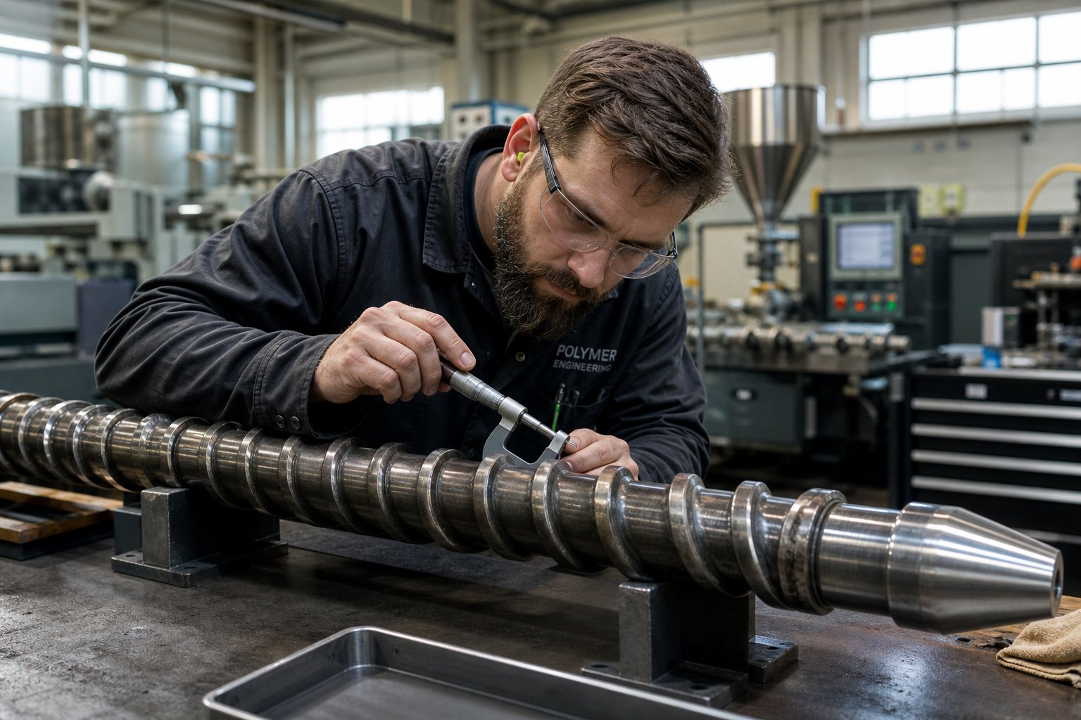
Measuring accurately requires the right tools and preparation. Davis-Standard's maintenance guidelines recommend using an OD bar micrometer — a standard outside-diameter micrometer modified with a bar that spans across the screw flights — to measure the outer diameter at multiple points along the screw length. Before any measurement, all solidified polymer residue must be removed using brass tools and copper gauze. Steel wire brushes or aggressive abrasives will damage the flight surfaces and produce false readings.
Measurements should be taken at regular intervals along the screw — every 2 to 3 diameters of length — and recorded against a reference map of the screw's original dimensions. Pay special attention to the transition zone and the entry to any mixing section, where solids wedging and high side forces create localized wear that can be far more severe than the average along the screw's length. When the screw is pulled, measure the barrel bore as well using an inside micrometer or ultrasonic thickness gauge at the feed, transition, and metering zones. An iron-based bimetallic barrel liner typically lasts about three times the service life of a screw, but abrasive materials or misalignment can shorten that dramatically.
Screw Materials, Coatings, and Surface Treatments
The base metal and surface treatment of your screws and barrels determine how fast wear progresses — and which wear mechanism dominates. Choosing the right combination for your application is as important as specifying the correct geometry.
| Material / Treatment | Typical Hardness | Best Application | Key Limitation |
|---|---|---|---|
| Nitrided Steel (4140/4150) | 50-55 HRC surface | General-purpose extrusion of unfilled polyolefins, PS — moderate-wear environments | Thin hardened case (0.010-0.020 in.) wears through relatively quickly with abrasive fillers |
| Tool Steels (D2, H13, CPM) | 58-62 HRC | Higher-wear applications; glass-filled resins; screws needing toughness and wear resistance together | Higher cost; limited corrosion resistance without additional surface treatment |
| Chrome Plating | 68-72 HRC surface | Corrosive resin processing (PVC, fluoropolymers); release-critical applications | Thin layer (typically 0.002-0.005 in.) can chip under impact or high side forces; does not resist abrasive wear well |
| Nickel-Boron Alloy Coatings | 55-62 HRC | Combined corrosion and moderate abrasion resistance; PVC and flame-retardant compounds | Moderate cost premium; less abrasion-resistant than carbide options |
| Tungsten Carbide Coatings / Stellite Hard-Facing | 55-70+ HRC | Highly abrasive materials — glass-filled PA, mineral-filled PP, recycled streams with contaminants | Highest cost; hard-facing on flight tips typically 0.060 in. thick and must be reapplied during refurbishment |
| Bimetallic Barrels | 55-68 HRC liner | Any application requiring extended barrel life; standard on production-grade extrusion and injection molding barrel and screw assemblies | Liner thickness (typically 0.060 in.) sets the total reline-able life; once worn through, full barrel replacement is required |
The same material-selection logic applies to injection molding screws, where abrasive glass-filled engineering resins and corrosive flame-retardant compounds impose identical wear demands on the plasticating unit. Whether you're running an extrusion line or an injection press, matching the screw surface treatment to the resin's wear profile is the single most effective way to extend service intervals.
Processing abrasive or corrosive materials accelerates every wear mechanism. Common abrasive fillers — glass fibers, silica, and calcium carbonate — concentrate their damage where channels have high levels of solids, particularly at the end of the melting section and the entry to mixers. Corrosive polymers like PVC and PVDF release acidic byproducts at processing temperatures, attacking unprotected steel surfaces between and beneath the flights. For these materials, a bimetallic barrel paired with a hard-faced or chrome-plated screw isn't a premium upgrade — it's the minimum viable specification.
When to Repair vs. Replace Your Extruder Screw and Barrel
This is the decision that separates cost-conscious maintenance from penny-wise waste. Refurbishment — typically welding new hard-facing onto worn flight tips and re-machining to original dimensions — costs significantly less than a new screw. But it isn't always the right call.
Here's a practical checklist. If any of these indicators apply, replacement is likely the better economic decision:
- Flight clearance has reached or exceeded four times (4x) the clearance when new — for a 3.5-inch screw, that means roughly 0.014 inches per side
- Hard-facing on the flight tips is completely worn through to the base metal
- The screw has already been refurbished three times — repeated welding deteriorates the base material and increases the risk of hard-facing delamination during operation
- Wear is concentrated in localized areas (transition zone entry, mixer inlet) severe enough that re-machining would compromise the screw root's structural integrity
- The rate reduction and discharge temperature increase caused by wear have reached a level where the line's profitability is materially impacted — some lines lose 10 to 15 percent of output capacity before the screw gets pulled
- Barrel bore measurements show the bimetallic liner has worn through or expanded beyond reline-able limits (typically greater than 0.20 mm increase from nominal)
Conversely, repair makes sense when wear is moderate, the screw has been refurbished fewer than three times, and the base metal remains sound. A properly refurbished screw with fresh hard-facing can deliver performance close to a new unit — at roughly 40 to 60 percent of replacement cost.
Keep a spare screw in storage so the worn unit can be pulled and sent for evaluation without shutting down the line for extended periods. Industry best practice is to have the replacement ready to install the same day the worn screw is removed, minimizing lost production time. For processors, equipment manufacturers, and maintenance teams sourcing custom or replacement screws and barrels — whether for extrusion lines or injection molding screws and barrels — NANHAIYA's screw barrel product center offers a practical starting point for evaluating options matched to your specific diameter, geometry, material grade, and surface treatment requirements.
The economics of this decision hinge on application criticality. Noncritical applications like corrugated pipe can tolerate screws with very high wear levels and still produce acceptable product. A medical-grade extrusion line, by contrast, may need replacement after the flight clearance reaches just 2x the original value because melt uniformity standards are far tighter. The right replacement threshold is always process-specific — defined by how much output loss, temperature rise, and quality variation your product and your margins can absorb.
Knowing when to replace, however, is only part of the equation. Knowing what to specify on the replacement order — understanding the numbers, codes, and tolerance classes on a screw specification sheet — is what ensures the new unit actually solves the problem the old one revealed.
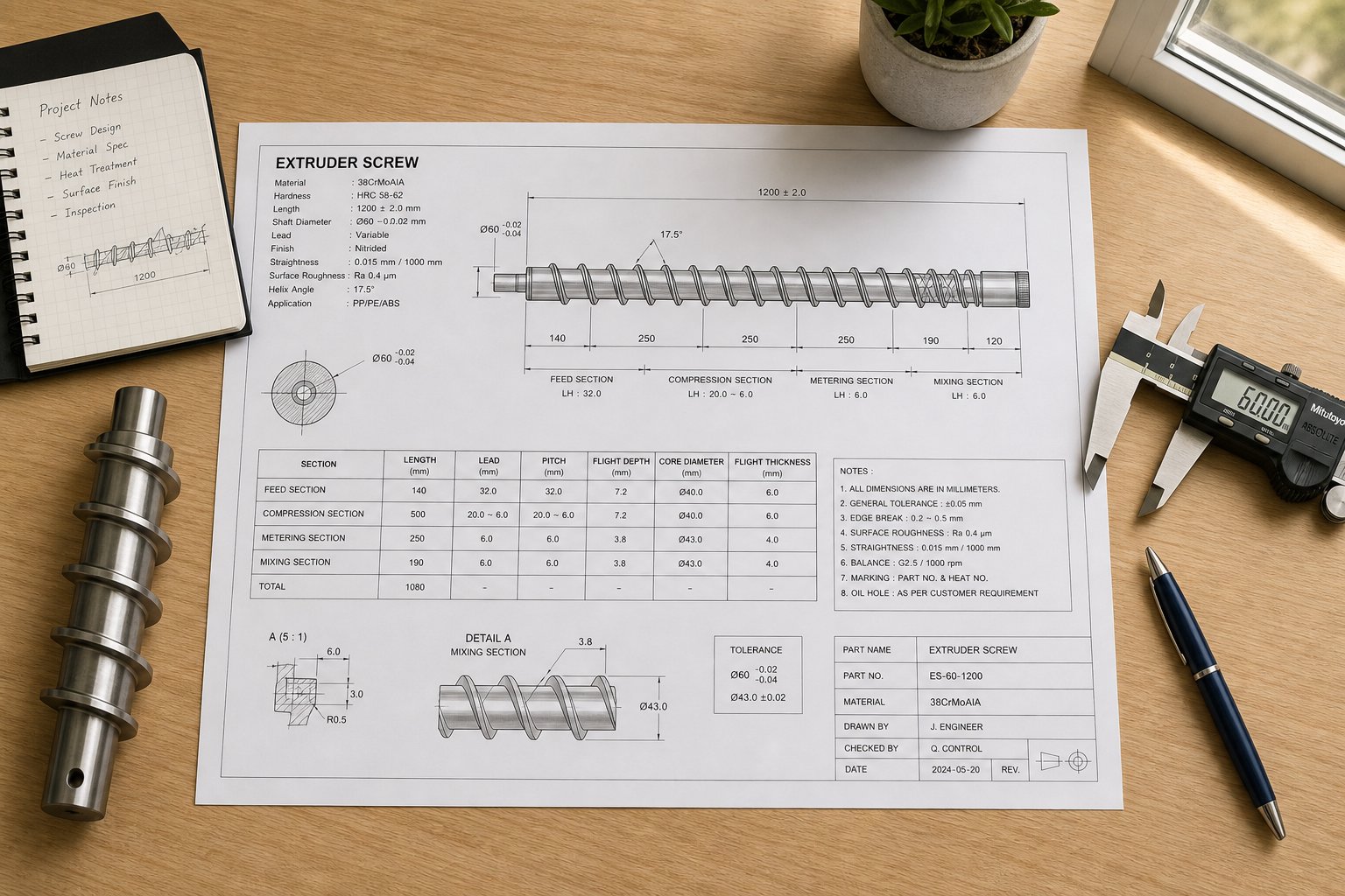
How to Read Extruder Screw Specifications and Choose Wisely
A specification sheet for an extruder screw can look like alphabet soup the first time you encounter one — diameter codes, L/D designations, material grades, coating abbreviations, and tolerance classes packed into a single-line description. But every character on that sheet maps directly to the geometry, metallurgy, and performance characteristics discussed throughout this article. Decoding those numbers is the difference between ordering a screw that solves your problem and ordering one that recreates it.
Reading an Extruder Screw Specification Sheet
Whether you're sourcing a replacement for a davis-standard extruder, evaluating used extruders on the secondary market, or specifying a new custom build, the datasheet follows a consistent structure. Here's how to work through it systematically:
- Identify the nominal diameter and L/D ratio. A designation like "90/30" means a 90 mm outer flight diameter with an L/D of 30:1 — giving a functional flighted length of 2,700 mm. Confirm that the diameter matches your barrel bore within the manufacturer's stated tolerance class. Even a fraction of a millimeter mismatch creates excessive clearance or, worse, metal-to-metal contact.
- Check the compression ratio. This will appear as a ratio (e.g., 3.2:1) or as separate feed and metering channel depth dimensions. Cross-reference against the polymer-specific recommendations from your process engineering data — a ratio optimized for HDPE will cause degradation if you're running rigid PVC.
- Verify the zone proportions. The spec sheet should break the screw length into feed, transition, and metering percentages or absolute lengths. A screw with a 50% feed zone behaves very differently from one with a 30% feed zone, even at the same L/D and compression ratio.
- Review the base material and surface treatment codes. Common designations include 4140 (nitrided steel), D2 or CPM (tool steel), "CrP" (chrome plated), and "WC" or "Stellite" (tungsten carbide or cobalt alloy hard-facing). Match these to your resin's abrasion and corrosion profile — the materials table from the wear section is your guide here.
- Confirm mixing section details. If the screw includes a Maddock, pin, or pineapple mixer, the spec should note its type, length in diameters, and position along the screw. Verify the mixer type aligns with your mixing needs — dispersive for agglomerate breakup, distributive for uniform blending.
- Check tolerance class and runout specifications. Flight OD tolerance, concentricity, and total indicated runout (TIR) define how precisely the screw was manufactured. Tighter tolerances cost more but deliver more consistent clearance and longer wear life. For critical applications, request documented inspection reports with actual measured values.
Key Specifications That Affect Performance and Cost
One of the most frequent questions processors ask is how much do screws cost — and the honest answer is that pricing varies enormously based on five primary drivers. Diameter and length set the baseline: a 150 mm screw requires exponentially more raw material and machining time than a 45 mm unit. Material grade is the next major lever — a nitrided 4140 steel screw costs a fraction of a bimetallic build with tungsten carbide hard-facing. Surface treatments like chrome plating or nickel-boron alloy coatings add cost but dramatically extend service life in corrosive environments. Custom geometry — barrier flights, specialized mixing sections, or non-standard compression profiles — increases engineering and programming time. Finally, tolerance class matters: a screw held to tight runout specifications requires more careful machining, inspection, and quality documentation.
Understanding these cost drivers helps you avoid two common purchasing mistakes. The first is over-specifying — ordering a tungsten-carbide-coated, barrier-flight screw with a Maddock mixer for a line that runs unfilled LDPE at moderate rates. The second, and more expensive in the long run, is under-specifying — choosing the cheapest general-purpose screw for a line processing glass-filled nylon, then replacing it every few months when wear destroys the geometry. General-purpose screws serve their role well on lines running a range of unfilled commodity resins at moderate output. Application-specific designs earn their premium on dedicated lines where material demands, throughput targets, or quality standards exceed what a standard three-zone geometry can deliver.
For processors evaluating US extruders — whether new lines or a used twin screw extruder for sale — the screw specification is the single most important document in the transaction. A davis standard extruder for sale at an attractive price becomes far less attractive if the screw inside it was designed for a completely different resin than what you plan to run. Always request the full screw specification and compare it against your process requirements before committing.
Making Confident Screw Selection Decisions
The knowledge built across this article — from zone functions and geometry parameters through polymer matching, mixing selection, troubleshooting, and wear diagnosis — converges at this point. Every line on a specification sheet corresponds to a design decision that affects melt quality, throughput, energy consumption, and service life. Reading those lines with comprehension transforms the purchasing process from guesswork into engineering.
Understanding every parameter on your extruder screw specification sheet — diameter, L/D, compression ratio, material grade, surface treatment, and tolerance class — is the single most effective way to ensure longer service life, fewer processing defects, and a better return on every screw you purchase.
When you're ready to translate that specification knowledge into an actionable sourcing step — whether for a custom new build, an OEM replacement, or a retrofit upgrade — NANHAIYA's screw barrel product center provides a practical resource for exploring options across diameters, geometries, material grades, and surface treatments for both extrusion and injection molding equipment. Matching what you've learned here to what's available ensures the next screw you install isn't just a replacement — it's an upgrade.
Frequently Asked Questions About Extruder Screws
1. What are the three zones of an extruder screw and what does each one do?
Every standard extruder screw is divided into a feed zone, a transition (compression) zone, and a metering zone. The feed zone has the deepest channel and conveys solid pellets forward from the hopper. The transition zone features a progressively shallower channel that compresses material, expels trapped air, and generates frictional heat to begin melting the polymer. The metering zone maintains a constant shallow depth to homogenize the melt thermally and pump it at a steady, uniform rate toward the die. The length proportion and depth change across these three zones define the screw's processing character for any given resin.
2. How do I choose the right compression ratio for my polymer?
Compression ratio selection depends primarily on the polymer's melting behavior and shear sensitivity. Semi-crystalline resins like HDPE and PP need higher compression ratios (typically 3:1 to 4:1) because their low bulk density and sharp melting point require aggressive compaction and energy input. Shear-sensitive materials like rigid PVC require much lower ratios (2:1 to 3:1) to avoid thermal degradation from excessive frictional heat. Amorphous resins such as PS and ABS generally tolerate a moderate range. Feedstock form also matters — PVC powder needs a higher ratio than PVC granules due to greater trapped air volume. Always cross-reference your specific formulation and additive loading against established industry guidelines before finalizing the ratio.
3. What is the difference between single-screw and twin-screw extruders?
Single-screw extruders use one rotating screw inside a barrel and excel at steady-state pumping of pre-compounded resins for applications like film blowing, pipe, and profile extrusion. They offer lower cost, simpler maintenance, and well-understood process behavior. Twin-screw extruders use two intermeshing screws and come in co-rotating or counter-rotating configurations. Co-rotating twins deliver intense, controllable mixing and are preferred for compounding, reactive extrusion, and devolatilization. Counter-rotating twins generate high pressure with gentler shear, making them ideal for rigid PVC processing. Twin-screw systems also feature modular screw elements that can be rearranged for different formulations, unlike the monolithic design of single-screw units.
4. How do I know when my extruder screw needs replacement instead of repair?
Key indicators that favor replacement over refurbishment include flight clearance exceeding four times the original new-screw clearance, hard-facing worn completely through to the base metal, the screw having already been refurbished three or more times, severe localized wear that compromises root structural integrity, and measurable output loss or discharge temperature increases that impact line profitability. If wear is moderate, the base metal is sound, and fewer than three rebuilds have been performed, refurbishment with fresh hard-facing can restore near-new performance at roughly 40 to 60 percent of the replacement cost. For sourcing custom or replacement screw and barrel solutions, NANHAIYA's product center at https://www.nhyscrew.com/products serves both extrusion and injection molding equipment needs.
5. Why does my extruder have output surging even after adjusting barrel temperatures?
Output surging is most commonly caused by inconsistent solids conveying in the feed zone rather than by downstream temperature imbalances. When the feed casing or screw root runs too hot, pellets soften prematurely, stick together, and form intermittent plugs that starve the compression and metering zones. This creates cyclic pressure oscillations that propagate to the die. Adjusting barrel temperatures in the heated zones downstream cannot fix a feed-zone problem. Effective solutions include ensuring adequate water cooling to the feed throat, extending the screw's internal cooling bore to cover the full solids conveying section, or upgrading to a grooved feed barrel that mechanically grips pellets regardless of surface temperature. Barrier screw designs also stabilize the solid bed and reduce surging tendencies.
Written by
Nanhaiya Technical Team
Zhoushan Nanhaiya Plastic Machinery Co., Ltd.
The Nanhaiya technical team supports screw and barrel manufacturing projects through application review, technical communication, custom manufacturing coordination, and production and quality control.
Discuss Your Application
Related Articles
More insights on screw barrel technology and plastics processing.

What Nobody Tells You About Screw Barrel For Plastic Machine Design
Oct 10, 2026
Learn how screw barrel for plastic machine design affects melt quality, throughput, and wear life. Covers geometry, resin matching, troubleshooting, and sourcing.
Read Article
Single Screw Extruder for Sheet: Stop Guessing, Start Specifying
Oct 9, 2026
Learn how to specify a single screw extruder for sheet production. Covers screw geometry, resin-specific processing, troubleshooting, and maintenance best practices.
Read Article
PE Pipe Extruder Machine: What Datasheets Won't Tell You
Oct 9, 2026
Learn how a PE pipe extruder machine works, key specs explained, material grade selection, maintenance tips, and buyer guidance beyond the datasheet.
Read ArticleLooking for something else?
Search by material, symptom or product and jump straight to the relevant page.
These are navigation suggestions based on keyword matching — not a quotation, not a delivery commitment, and not a substitute for engineering review. Final specification is confirmed by our engineers against your drawings and processed material.
Need help with screw barrel selection?
Share your machine model, processed material and application. Our team can help with pricing and technical support.