

What Are Extruder Parts and Why Every Component Matters
Your slicer settings look perfect. Your bed is leveled. Your filament is fresh out of the bag. And yet, the print fails — under-extrusion on one layer, stringing on the next, or a mysterious clog that kills the job halfway through. Sound familiar? Before you spend another hour tweaking retraction values, consider this: the problem might not be software at all. It might be your extruder parts.
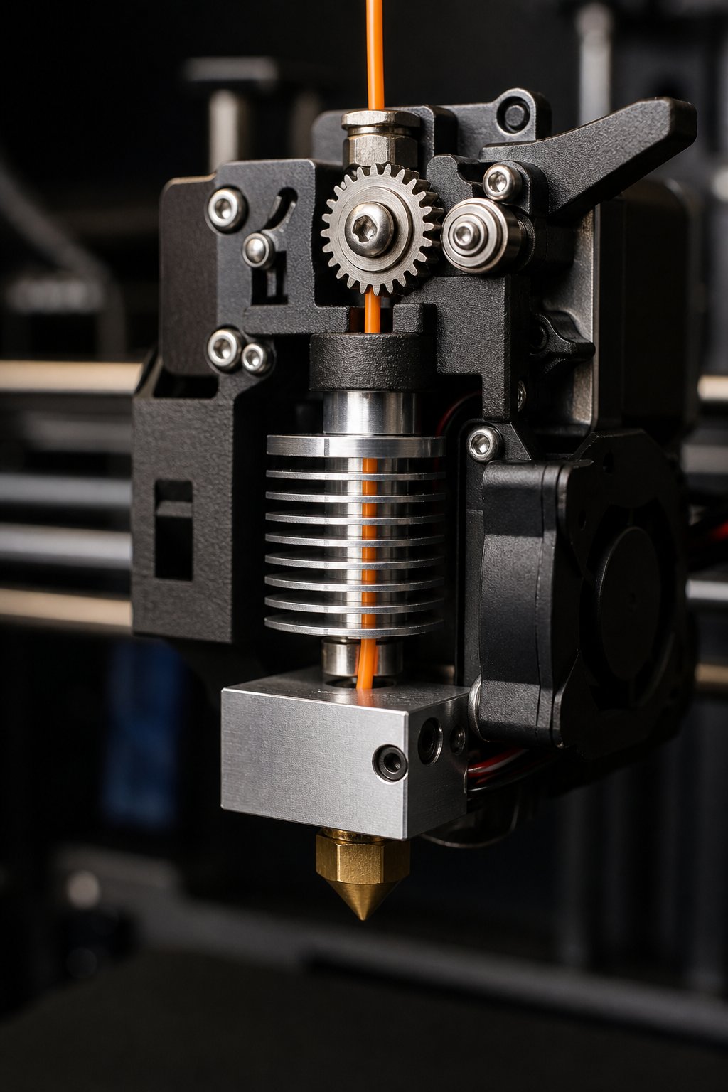
Extruder parts are the collection of mechanical and thermal components inside your 3D printer extruder that work together to grip, guide, melt, and deposit filament material layer by layer. They include everything from the drive gears that push plastic forward to the nozzle tip that shapes each deposited line. Together, these components form a finely tuned system — and when even one element falls out of spec, print quality suffers in ways that no slicer adjustment can fix.
Think of this guide as a mechanic's manual for your extruder. Rather than skimming definitions, you'll follow a strand of filament on its complete journey — from the spool all the way to the printed layer — meeting each part of a 3D printer extruder in the exact sequence it encounters them. By the end, you'll understand not just what each component does, but how it fails, what it's made of, and when to replace it.
What Exactly Are Extruder Parts
So, what is an extruder on a 3D printer in practical terms? It's a system of interdependent components organized into three functional categories: the feeding mechanism (which grips and advances the filament), the thermal system (which manages heat to melt it at precisely the right point), and the deposition system (which shapes and places the molten material). Every part within these categories must work in harmony — the drive gears must push filament at a rate the heater can melt, and the nozzle must deposit it at a diameter the slicer expects.
Here's a scannable overview of the primary extruder parts you'll encounter throughout this article:
- Drive gears — grip the filament and push it forward using a stepper motor
- Idler bearing/tensioner — applies pressure against the drive gear to maintain consistent grip
- Filament path tubes (PTFE) — guide the filament from the feeder to the hotend with minimal friction
- Heatsink — dissipates heat to prevent premature softening above the melt zone
- Heatbreak — creates a sharp thermal transition between cool and hot zones
- Heat block — houses the heater cartridge and thermistor, forming the primary melt chamber
- Thermistor — measures temperature for precise thermal regulation
- Heater cartridge — converts electrical energy into the heat needed to melt filament
- Nozzle — shapes and extrudes molten material at a specific diameter
Each of these components has a direct influence on whether your printer produces clean, dimensionally accurate parts — or generates a pile of spaghetti.
Why Every Part Matters for Print Quality
Understanding what is extruder in 3D printing goes far beyond knowing it "melts plastic." Every single component in the extruder operates within specific tolerances. A drive gear with rounded teeth loses its grip and grinds filament into dust. A worn PTFE tube introduces wobble in the filament path, causing inconsistent extrusion. A degraded thermistor feeds inaccurate temperature data to the firmware, leading to under-heated or overheated plastic. The result? Under-extrusion, stringing, clogs, poor layer adhesion — problems that look like slicer bugs but are actually hardware failures.
The critical insight here is that these components are interdependent. A partially clogged nozzle doesn't just reduce flow — it creates back-pressure that causes the drive gear to grind filament, which produces debris that contaminates the filament path, which accelerates wear on the PTFE tube. One failing part cascades into system-wide degradation.
Understanding your extruder parts transforms reactive troubleshooting into proactive maintenance — catching a worn component before it ruins a print is always cheaper and faster than diagnosing failures after the fact.
This guide takes that mechanic's-manual approach for every component. You'll learn each part's function, its common failure modes, the materials it's made from and why, and practical guidance on inspection and replacement. Whether you're running a single desktop machine or managing a fleet of printers in a production environment, the filament journey ahead will change how you think about every extrusion problem you encounter.
The journey starts where the filament does — at the spool, where it first makes contact with the drive mechanism and begins its transformation from a rigid strand into a precisely deposited layer.
The Complete Filament Path From Spool to Printed Layer
Imagine holding a single strand of filament between your fingers. It's rigid, room-temperature plastic — nothing more than a long, thin rod wound around a spool. Over the next few seconds of printing, that strand will be gripped, pushed, guided, heated past its glass transition temperature, liquefied, and squeezed through a tiny opening to form a precise bead of material. Every extruder part it encounters along the way plays a specific role in that transformation. Miss one step, and the entire chain breaks down.
Walking through this path in sequence — the exact order filament travels from spool to printed layer — is the single most useful mental model for diagnosing 3D printer extrusion problems. If you know what should be happening to the material at each stage, you can pinpoint exactly where things go wrong.
From Spool to Drive Gear and Into the Filament Path
The filament's journey begins the moment it leaves the spool holder and enters the extruder feeder system. This is the first point of mechanical contact, and it's deceptively important.
A spring-loaded idler arm (or tensioner) presses the filament firmly against a drive gear — a small, toothed wheel typically mounted directly on a stepper motor shaft. The teeth on this gear bite into the filament surface just enough to grip it without deforming it. When the stepper motor turns, the gear pushes the filament forward at a controlled, firmware-determined rate. Some systems use a single drive gear paired with a smooth idler bearing, while dual-drive designs use two interlocking toothed gears for symmetrical grip on both sides of the filament. Dual-gear setups deliver noticeably more consistent feeding, especially with softer or flexible materials that tend to compress under one-sided pressure.
The tension setting here matters more than most users realize. Too little spring pressure and the gear slips, causing under-extrusion. Too much, and the teeth dig too deeply — deforming the filament and shaving off tiny plastic curls that accumulate as debris inside the feeder. Those shavings eventually migrate downstream, contributing to partial clogs that are frustratingly hard to trace back to their source.
After clearing the drive gear, the filament enters a guide channel or a PTFE (polytetrafluoroethylene) tube that routes it toward the hotend. The characteristics of this tube segment vary dramatically depending on the extruder architecture. In a direct drive 3D printer extruder, the path is extremely short — often under 30 millimeters — because the motor and gear assembly sits directly on top of the hotend. In a Bowden system, however, filament may travel through 300 to 600 millimeters of PTFE tubing before reaching the melt zone. That difference in path length directly affects friction, retraction responsiveness, and how well the printer handles flexible filaments. Regardless of architecture, the inner diameter of this tube must be smooth and consistent. Even minor internal roughness or diameter variations introduce drag that the drive gear must overcome, and that drag shows up as inconsistent extrusion width on the printed part.
Through the Hotend and Out the Nozzle Tip
The real transformation begins once the filament enters the hotend — the thermal heart of the extruder in a 3D printer. Here, a carefully engineered sequence of components controls exactly where and how heat is applied.
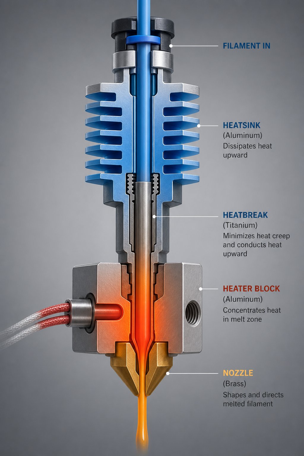
First, the filament passes through the heatsink, a finned metal structure (usually aluminum) with an active cooling fan blowing air across it. The heatsink's job is counterintuitive — it keeps filament cool in a zone that sits just millimeters away from a 200°C+ melt chamber. Without effective heat dissipation here, thermal energy creeps upward through the assembly, softening the filament too early. This phenomenon, known as heat creep, causes the partially softened plastic to swell and jam inside the narrow filament path — one of the most common and frustrating failure modes in FDM printing.
Directly below the heatsink sits the heatbreak — a thin-walled metal tube that serves as the thermal transition zone between the cool upper section and the hot lower section. The heatbreak is engineered to conduct as little heat as possible upward while still providing a smooth internal bore for the filament to slide through. This is why heatbreaks are typically made from stainless steel or titanium alloy — metals with relatively low thermal conductivity compared to aluminum or copper. In PTFE-lined hotends, a section of tube extends down through the heatbreak to the top of the melt zone. In all-metal designs, the filament contacts bare metal throughout, which allows printing at temperatures above 240-260°C where PTFE begins to degrade.
The filament then enters the heat block — a solid metal block (commonly aluminum) that houses two critical components: the heater cartridge and the thermistor. The heater cartridge is a resistive heating element, typically rated at 30-50 watts for standard desktop printers, that converts electrical energy into the thermal energy required to melt the filament. The thermistor sits in a separate bore within the same block, continuously measuring the block's temperature and feeding that data back to the printer's control board. This closed-loop feedback system maintains the target temperature within a few degrees — essential because even a 10°C deviation can mean the difference between smooth extrusion and a partial clog.
Inside the heat block, the filament transitions from solid to molten over a span of just a few millimeters. This melt zone is surprisingly small, and its effectiveness depends entirely on the heater cartridge delivering enough wattage to keep up with the rate at which the drive gear pushes cold filament in. Print too fast without enough thermal capacity, and the plastic exits the nozzle only partially melted — producing weak layers with poor adhesion.
Finally, the molten material reaches the nozzle — a small, precisely machined component threaded into the bottom of the heat block. The nozzle tapers the filament path down from the internal bore diameter (typically around 2mm) to the outlet diameter, most commonly 0.4mm. This constriction shapes the extruded bead to a consistent width and creates the back-pressure needed to control material flow. The nozzle is the last extruder part the filament touches before it becomes a printed layer on the build surface.
Here's a quick-reference summary of the entire 3D print extruder path, from start to finish:
- Spool holder — filament unwinds and feeds toward the extruder feeder
- Drive gear and idler — stepper motor-driven teeth grip the filament and push it forward at a controlled rate
- Filament guide or PTFE tube — channels the filament from the feeder toward the hotend with minimal friction
- Heatsink — actively cooled fins dissipate heat to prevent premature filament softening
- Heatbreak — a narrow thermal bridge that isolates the cool zone from the melt zone
- Heat block — houses the heater cartridge and thermistor, creating the primary melt chamber
- Nozzle — constricts and deposits the molten filament at a precise diameter onto the build surface
This seven-stage path is universal across virtually every FDM printer on the market. The specific parts may differ in size, material, or arrangement, but the sequence remains the same. And that's precisely what makes this mental model so powerful for troubleshooting: if you're seeing under-extrusion, you can mentally walk the filament path and ask — is the drive gear gripping properly? Is the PTFE tube clear? Is the heatsink fan running? Is the heatbreak clogged? Is the heater reaching temperature? Is the nozzle worn?
Each question points to a specific component, and each component can be inspected individually. You're no longer guessing — you're diagnosing.
Of course, where each of these parts physically sits relative to one another depends heavily on whether your printer uses a direct drive or Bowden architecture — two fundamentally different approaches to arranging the same set of components, each with its own strengths and trade-offs.
Bowden vs Direct Drive Extruder Systems and Their Unique Parts
The same set of extruder parts — drive gears, PTFE tubes, heatsinks, heatbreaks, nozzles — appears in virtually every FDM printer. But where those parts sit relative to each other changes everything about how the system performs. Two dominant architectures have emerged in the 3D printing extruders landscape: direct drive and Bowden. Each arranges the same core components differently, and that arrangement dictates filament path length, retraction behavior, print speed potential, and which materials your machine can reliably handle.
Understanding the physical layout of each system isn't just academic. It determines which replacement components you need, how you troubleshoot feeding issues, and whether a particular upgrade is even compatible with your setup.
How Direct Drive Extruder Parts Are Arranged
In a direct drive 3D printer extruder, the stepper motor and drive gear assembly mount directly on top of the hotend. The filament travels just 1 to 3 millimeters from the point where the gear teeth grip it to the entrance of the melt zone. Some designs include a short PTFE liner of roughly 30 to 40 millimeters inside the hotend, while others — particularly all-metal configurations — eliminate the tube entirely.
This ultra-short filament path is the defining advantage. Because there's almost no distance between the drive gear and the melt zone, the extruder 3D printer responds almost instantly when the firmware commands a push or pull. Retraction distances drop dramatically — typically 0.5 to 1.5 millimeters compared to 4 to 7 millimeters on Bowden setups. That responsiveness is critical for flexible filaments like TPU, which tend to buckle and wrap around the drive gear when forced through a long tube. A 3D printer with direct drive extruder can reliably feed materials as soft as Shore 75A to 85A, while most Bowden systems struggle below Shore 95A.
The parts unique to or optimized for direct drive reflect the need to minimize print head weight:
- Compact or pancake stepper motors — NEMA 14 or shortened NEMA 17 motors (42-25 or 42-20 variants) that weigh 140 to 220 grams instead of the standard 280 grams
- Lightweight extruder housings — often CNC-machined aluminum or reinforced polymer to keep total assembly mass low
- High-ratio geared drive systems — designs like the Orbiter V2 (7.5:1 gear ratio at just 140 grams including motor) multiply torque so a smaller, lighter motor can deliver strong filament grip
- Short-path heatbreaks — optimized for the minimal distance between the drive gear and melt zone
- Integrated cooling solutions — combined heatsink and fan assemblies designed to fit within the compact direct drive footprint
The tradeoff? All that motor and gearbox mass rides on the print head. A typical direct drive assembly adds 100 to 250 grams compared to a Bowden hotend alone. That extra weight limits how aggressively the printer can accelerate and decelerate the carriage before ringing — visible ghosting artifacts — appears on printed surfaces. On bed-slinger machines with a single Z lead screw, the added weight can even cause the X gantry to sag on the unsupported side, producing a subtly tilted first layer.
How Bowden Systems Relocate Key Parts
A Bowden extruder takes a fundamentally different approach: it separates the drive mechanism from the hotend entirely. The stepper motor and drive gear assembly mount on the printer's frame — often near the top or rear — while the hotend sits on the moving carriage. Filament bridges the gap through a long PTFE tube, typically 300 to 600 millimeters in length, held in place at each end by pneumatic push-fit couplers.
This separation introduces a set of parts you won't find on a direct drive system:
- Long PTFE tubes — the defining component of the Bowden architecture, these must have a consistent inner diameter and smooth bore to minimize friction over the extended path
- Pneumatic couplers (push-fit connectors) — secure the PTFE tube at the extruder end and the hotend end; these are a common failure point when the internal teeth wear and the tube slips under retraction force
- Lightweight hotend assemblies — because the motor stays on the frame, the carriage carries only the hotend, cooling fans, and part-cooling duct
The primary advantage is speed. With the heavy stepper motor removed from the carriage, moving mass drops to 250 to 350 grams, allowing higher accelerations — often 1,500 to 3,000 mm/s² — without introducing ringing artifacts. For printers that run primarily PLA and PETG, a well-tuned Bowden setup delivers excellent results at faster travel speeds.
The cost of that speed shows up in filament control. Pushing plastic through 400+ millimeters of tube is, mechanically, like pushing a rope. The filament column inside the tube compresses slightly under pressure, creating a delay between when the stepper motor moves and when material actually exits the nozzle. This elasticity effect means retraction distances must be significantly longer — 4 to 7 millimeters — to pull the filament back far enough to prevent oozing. Even then, a tiny gap between the PTFE tube end and the nozzle can trap molten material, producing persistent stringing that no retraction setting fully eliminates.
Flexible filaments amplify every one of these issues. Soft materials like TPU compress more inside the tube, buckle at the pneumatic couplers, and resist the long retractions that Bowden systems require. If you're printing anything below Shore 95A hardness, a Bowden setup will fight you at every step.
Here's a side-by-side comparison of how these two architectures differ across the dimensions that matter most for everyday printing:
| Dimension | Direct Drive | Bowden |
|---|---|---|
| Filament Path Length | 1-40 mm | 300-600 mm |
| Typical Retraction Distance | 0.5-1.5 mm | 4-7 mm |
| Moving Print Head Mass | 350-550 g | 250-350 g |
| Flexible Filament Compatibility | Excellent (Shore 75A+) | Limited (Shore 95A+ only) |
| Maximum Acceleration (Bed-Slinger) | 500-1,500 mm/s² | 1,500-3,000 mm/s² |
| Stringing Tendency | Lower | Higher (PTFE gap ooze) |
| Maintenance Complexity | Moderate (heavier assembly to remove) | Higher (tube wear, coupler failure, longer path to inspect) |
| Key Unique Parts | Compact stepper, geared drive, integrated cooling | Long PTFE tube, pneumatic couplers, frame-mounted feeder |
So which architecture should you choose? The answer depends entirely on what you print most often. If your workflow revolves around PLA and PETG at moderate to high speeds, a Bowden system's lighter carriage and faster acceleration deliver real productivity gains. If you regularly work with flexible filaments, abrasive composites, or materials demanding precise retraction control, a direct drive setup eliminates entire categories of feeding problems. And for large-format bed-slinger printers where carriage weight directly impacts print quality, the lighter Bowden hotend often wins on pure output quality at speed — unless you invest in an ultralight geared extruder specifically designed to minimize the direct drive weight penalty.
Whichever system your printer uses, the individual components within it — gears, tubes, heatbreaks, nozzles — are all made from specific materials chosen for very particular reasons. Those material choices quietly determine how long each part lasts, which filaments it can handle, and when it'll need replacing.
Extruder Part Materials and How They Affect Performance
You wouldn't install brake pads made of plastic on a car and expect them to survive highway speeds. The same logic applies to every component in your 3D printing extruder — the material each part is made from directly determines how well it conducts heat, how long it resists wear, and which filaments it can handle before failing. Yet most users never consider why their nozzle is brass, why their heatbreak is stainless steel, or why a premium PTFE tube costs five times more than a generic one. These aren't arbitrary manufacturing choices. They're engineering decisions that shape every print you make.
Understanding what your 3d printer extruder parts are made of — and why — gives you the knowledge to choose replacements that actually match your printing needs instead of grabbing whatever shows up first in a search result.
Nozzle Materials From Brass to Ruby-Tipped
The nozzle sits at the very end of the extrusion head, directly shaping every line of molten plastic your printer deposits. It endures constant thermal cycling, abrasive particle contact, and mechanical stress from bed-leveling mishaps. The material it's made from determines how efficiently it transfers heat into the filament, how quickly it wears under abrasive conditions, and ultimately how many hours of printing you'll get before it needs replacing.
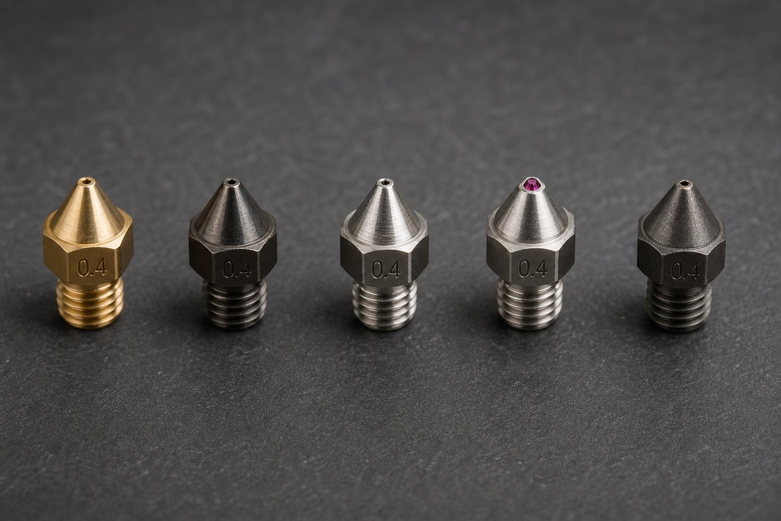
Brass is the industry default, and for good reason. With a thermal conductivity of roughly 120 W/m·K, brass transfers heat from the heat block into the filament extremely efficiently, ensuring consistent melt quality even at higher print speeds. It's also inexpensive — typically $0.50 to $2 per nozzle — and easy to machine to tight tolerances. For non-abrasive filaments like PLA, PETG, and TPU, a brass nozzle can last six to twelve months of regular use before the bore widens enough to affect extrusion accuracy.
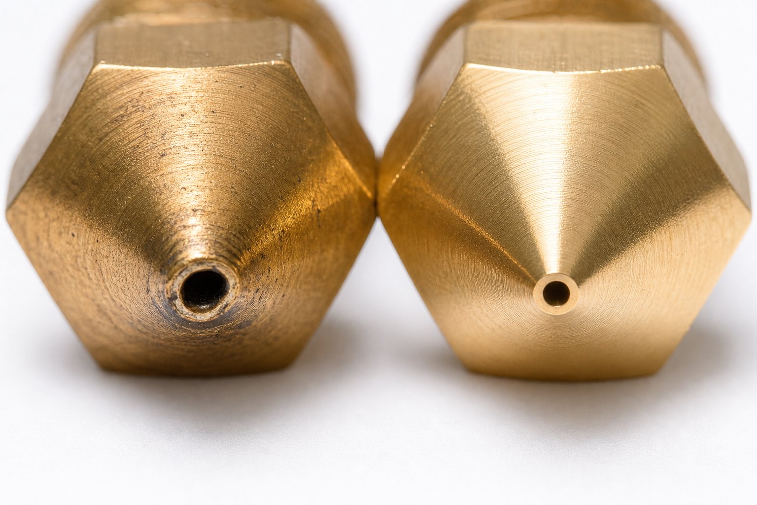
The problem appears the moment you introduce abrasive materials. Carbon fiber-filled, glass fiber-filled, and even glow-in-the-dark PLA contain hard particles that erode brass rapidly. A nozzle comparison study found that a brass nozzle's bore can widen from 0.4mm to over 0.6mm after just one to three prints with carbon fiber filament — the exit hole becoming visibly oval. At that point, your slicer expects 0.4mm extrusion lines, but the nozzle delivers something wider and less controlled. Layer adhesion suffers, dimensional accuracy drops, and you're chasing a software fix for a hardware problem.
Hardened steel nozzles solve the wear problem but introduce a tradeoff. Their thermal conductivity falls to approximately 20-30 W/m·K — roughly four times lower than brass. That means the nozzle transfers heat into the filament more slowly. A hardened steel nozzle reading 210°C at the thermistor may deliver only around 195°C to the actual melt zone. You'll need to increase your temperature setpoint by 5 to 10°C to compensate and should run a PID autotune after switching materials. The payoff is durability: expect six to twelve months of life even with abrasive composites.
Stainless steel occupies a middle ground. Its wear resistance sits between brass and hardened steel, and its lower thermal conductivity (around 15 W/m·K) requires temperature offsets of 7 to 12°C. Where stainless steel shines is in food-safe or medical-adjacent applications where material purity matters and brass's lead content is unacceptable.
Ruby-tipped nozzles take a clever hybrid approach: a brass body for excellent thermal conductivity paired with a synthetic ruby insert at the orifice for extreme wear resistance. You get brass-like heat transfer with a tip that can survive thousands of hours of abrasive filament. The catch? They're brittle. A nozzle crash into the bed can chip the ruby, instantly destroying a $60-100 component. Only install these on printers with reliable bed-leveling systems.
Tungsten carbide nozzles offer the best all-around combination of properties: thermal conductivity of 80-110 W/m·K (not far from brass), extreme hardness, and multi-year lifespans with abrasive materials. They require minimal temperature compensation and resist chipping better than ruby. The trade-off is price — $30 to $60 per nozzle — which makes them a better fit for production environments than casual hobbyist use.
| Nozzle Material | Thermal Conductivity (W/m·K) | Abrasion Resistance | Ideal Filament Types | Approximate Lifespan (Non-Abrasive / Abrasive) | Price Range |
|---|---|---|---|---|---|
| Brass | ~120 | Low | PLA, PETG, TPU, ABS | 6-12 months / 1-3 prints | $0.50-$2 |
| Hardened Steel | 20-30 | High | CF, GF composites, glow PLA | 2+ years / 6-12 months | $5-$15 |
| Stainless Steel | ~15 | Medium | Food-safe applications, mild abrasives | 2+ years / 6-12 months | $3-$8 |
| Ruby-Tipped | ~120 (brass body) | Extreme | High-abrasion composites on reliable machines | 3+ years / 3+ years | $60-$100 |
| Tungsten Carbide | 80-110 | Extreme | All materials, production environments | 5+ years / 5+ years | $30-$60 |
Heatbreak and Drive Gear Material Considerations
While nozzle material tends to grab most of the attention, the heatbreak and drive gears are equally material-sensitive — they just fail more quietly.
The heatbreak's entire purpose is to limit how much heat migrates from the melt zone upward into the cold zone. Its material determines how sharp that thermal transition is. Most heatbreaks ship in stainless steel, which has a thermal conductivity around 15 W/m·K — low enough to create a reasonable barrier between the 200°C+ heat block and the cooled heatsink above it. For standard PLA and PETG printing, stainless steel heatbreaks work reliably.
Titanium alloy heatbreaks push this further. Titanium's thermal conductivity drops to roughly 7 W/m·K — about half that of stainless steel — creating a much steeper thermal gradient across the same physical length. That sharper transition means the filament stays solid longer as it approaches the melt zone, significantly reducing the risk of heat creep. For users printing high-temperature engineering polymers like polycarbonate or nylon — materials that require hotend temperatures of 260-300°C — a titanium heatbreak can mean the difference between reliable multi-hour prints and recurring mid-print jams caused by premature filament softening in the cold zone.
Drive gears face a different material challenge: they need to grip filament firmly enough to push it forward without wearing down under constant friction. Hardened steel is the standard choice for the gear teeth. Its surface hardness maintains sharp tooth profiles through thousands of hours of continuous feeding. Softer metals — or poorly hardened steel variants found in some budget printers — develop rounded teeth over time, especially when running abrasive composite filaments. Once the teeth lose their edge, the gear slips instead of gripping, producing the classic symptom of filament grinding without extrusion.
Dual-gear systems, where both the drive gear and the idler have teeth, distribute the gripping force across twice the filament surface area. This matters for material longevity as well — each individual tooth engages the filament with less force, reducing the wear rate on both the gears and the filament itself.
Finally, there's the often-overlooked PTFE tube. Standard-grade PTFE tubes work well at typical PLA printing temperatures (190-220°C), but they begin to soften and degrade at sustained temperatures above 240°C. This is why PTFE-lined hotends have a hard ceiling for filament temperature — push past it, and the tube deforms internally, narrowing the filament path and eventually causing jams. Premium PTFE variants, like Capricorn XS tubes, are manufactured with tighter tolerances and higher temperature resistance than generic options, extending that ceiling to approximately 250-260°C. They also offer lower friction and more consistent inner diameter, which directly reduces the feeding resistance — a particularly meaningful improvement in Bowden systems where the filament travels through 300+ millimeters of tube.
Even so, premium PTFE has limits. For any additive manufacturing extruder running polycarbonate, nylon, or other filaments above 260°C, an all-metal heatbreak that eliminates the PTFE liner entirely is not optional — it's mandatory. The PTFE simply cannot survive those temperatures without degrading, releasing fumes, and contaminating the filament path.
Knowing what each component is made from — and why that material was chosen — shifts your approach from guessing at replacements to selecting them with purpose. A brass nozzle isn't "cheap"; it's thermally optimal for non-abrasive materials. A titanium heatbreak isn't "premium for the sake of it"; it's an engineering solution to a specific thermal management problem. Every material choice is a performance decision, and the right combination of materials across your nozzle, heatbreak, drive gears, and PTFE tube should match the filaments and temperatures you actually print with.
Material selection becomes even more nuanced when you factor in nozzle diameter — another variable that most users treat as a fixed default rather than a tunable parameter with profound effects on speed, detail, and filament compatibility.
Nozzle Sizes and Their Impact on Print Quality and Speed
Most 3D printers ship with a 0.4mm nozzle installed, and most users never swap it out. According to a Prusa Research survey, only about 20% of users have ever tried a different nozzle diameter. That means 80% of the printing community is leaving significant performance on the table — printing slower than necessary for large parts, or accepting less detail than they could achieve on small ones. The extruder nozzle is one of the most affordable and easiest components to change, yet it's one of the most ignored.
Nozzle diameter isn't just a number stamped on a tiny brass cone. It determines how wide each deposited line can be, which sets the minimum feature size your printer can resolve horizontally. It dictates how tall each layer can safely go, affecting vertical resolution and print speed simultaneously. And it interacts directly with other extruder parts — particularly the heater cartridge and heat block — in ways that can make or break high-speed printing. Choosing the right nozzle size for your application is one of the highest-leverage decisions you can make without spending more than a few dollars.
Standard Nozzle Sizes and What Each Delivers
Five nozzle diameters cover the vast majority of extrusion 3D printer use cases. Each occupies a distinct niche along the speed-versus-detail spectrum, and understanding where each one excels helps you match hardware to the job instead of forcing every print through the same 0.4mm opening.
0.2mm — The precision specialist. This nozzle produces extrusion lines as narrow as 0.24mm, capturing fine text, thin walls, and delicate geometry that larger nozzles simply blur over. It's ideal for jewelry prototypes, miniature figurines, and parts with embossed logos. The tradeoff is speed: print times can easily triple or quadruple compared to a 0.4mm nozzle on the same model. There's also a higher clogging risk, since the tiny bore is less forgiving of contaminants or filament particles larger than about 80 microns.
0.4mm — The industry default. This diameter strikes the best overall balance between detail, speed, and reliability. It handles layer heights from 0.1mm to 0.32mm, supports volumetric flow rates around 30 mm³/s on a properly tuned hotend, and works with nearly every filament type. If you only ever own one nozzle, this is the one — and it's the benchmark that all slicer profiles are built around.
0.6mm — The quiet productivity booster. Stepping up from 0.4mm to 0.6mm can cut print times nearly in half while sacrificing surprisingly little visible quality on most objects. Flower pots, enclosures, brackets, and cosplay props all look nearly identical whether printed with a 0.4mm or 0.6mm nozzle, yet the time savings are dramatic. Impact testing has also shown that objects printed with a 0.6mm nozzle absorb up to 25.6% more energy than those printed with a 0.4mm nozzle — the wider extrusion lines create greater bonding surface between layers, producing tougher parts.
0.8mm — Built for rapid prototyping and structural components. At this diameter, layer heights of 0.4mm to 0.64mm are practical, and prints that took eight hours with a 0.4mm nozzle can finish in two to three. Surface detail is visibly reduced — you'll see layer lines clearly on curved surfaces — but for functional prototypes, jigs, fixtures, and test-fit parts, the speed gain far outweighs the cosmetic loss.
1.0mm — Maximum throughput for large functional parts. A 1.0mm nozzle can achieve up to five times the speed of a 0.4mm nozzle. Layer heights of 0.5mm or higher produce a distinctive ribbed texture that's actually desirable for certain applications — children's toys benefit from naturally rounded edges, and transparent PETG prints refract light in striking patterns. The nozzle is also virtually clog-proof due to the wide bore.
The fundamental relationship to remember: nozzle diameter controls horizontal resolution (X/Y plane), while layer height controls vertical resolution (Z axis). These are independent variables — you can print a 0.05mm layer height through a 0.6mm nozzle if you want smooth vertical surfaces without sacrificing horizontal speed. Treating them as separate levers unlocks much more flexible print strategies.
| Nozzle Size | Recommended Layer Height Range | Typical Print Speed | Detail Level | Best Use Cases |
|---|---|---|---|---|
| 0.2mm | 0.05 - 0.15mm | 15 - 30 mm/s | Ultra-fine | Miniatures, jewelry, embossed text, logos |
| 0.4mm | 0.10 - 0.32mm | 40 - 80 mm/s | Standard | General-purpose printing, balanced prototypes |
| 0.6mm | 0.15 - 0.48mm | 50 - 100 mm/s | Moderate | Enclosures, holders, vases, functional parts |
| 0.8mm | 0.20 - 0.64mm | 50 - 100 mm/s | Low | Rapid prototyping, jigs, structural components |
| 1.0mm | 0.25 - 0.75mm | 40 - 80 mm/s | Coarse | Large functional parts, draft prints, toys |
Matching Nozzle Size to Filament and Application
Picking a nozzle diameter isn't just about speed and detail — it also has to match your filament, your hotend's thermal capacity, and your printer's thread standard. Get any of these wrong, and you'll introduce problems that no amount of slicer tuning can resolve.
The practical rule for layer height is straightforward: stay between 25% and 75% of your nozzle diameter. For a 0.4mm nozzle, that means 0.1mm to 0.3mm layers. Drop below 25%, and the nozzle squishes material so flat that layer adhesion suffers and surface quality actually degrades. Exceed 75%, and the bead doesn't flatten enough to bond properly with the layer below — you'll see gaps, weak walls, and delamination. A good starting point is 50% of nozzle diameter (0.2mm layers for a 0.4mm nozzle), then fine-tune from there based on your specific project goals.
Larger nozzles introduce a thermal demand that many users overlook. When you jump from a 0.4mm to a 0.8mm nozzle, the volume of plastic passing through the melt zone per second doesn't just double — it roughly quadruples, since flow scales with cross-sectional area. Your heater cartridge now has to melt significantly more material in the same timeframe. A standard 30W heater cartridge that keeps up easily at 0.4mm may struggle to maintain target temperature at 0.8mm during fast infill passes. The thermistor reads a temperature drop, the firmware ramps up heating, but if the wattage ceiling is too low, the filament exits partially molten. The result is weak layers and poor inter-layer adhesion — a problem that looks like a slicer flow issue but is actually a thermal bottleneck in the heat block. This is a perfect example of how extruder parts are interdependent: the nozzle size you choose must be supported by adequate heater cartridge wattage.
Filament diameter interacts with nozzle selection as well. Most consumer printers — especially any extruder for 1.75mm 3D printer systems — use 1.75mm filament, while some machines (particularly older or industrial models) run 2.85mm stock. The nozzle bore must be significantly smaller than the filament diameter to create back-pressure for controlled extrusion, so you won't find 1.0mm nozzles commonly used on 1.75mm systems without high-flow hotend modifications. On 2.85mm systems, larger nozzles integrate more naturally because the greater filament volume entering the melt zone supports higher flow rates.
Specialty filaments add another constraint. Materials containing particles or fibers — carbon fiber, glass fiber, wood fill, metal fill — require minimum nozzle diameters to prevent clogging. As a general rule, any filled filament needs at least a 0.6mm nozzle, though some manufacturers recommend 0.8mm for heavily loaded composites. Even with a pellet head extruder designed for industrial throughput, nozzle bore diameter must exceed the largest particle size in the feedstock by a comfortable margin, or jams become inevitable.
Finally, verify thread compatibility before purchasing any replacement nozzle. The M6 x 1.0mm thread standard dominates consumer hotends — both V6-style and MK8-style nozzles use it, though they differ slightly in thread length and hex head size. Some proprietary printers use non-standard threading entirely. Installing a nozzle with the wrong thread pitch or length can cross-thread the heat block, damage the sealing surface, or leave a gap between the nozzle and heatbreak that leaks molten filament internally. Always check your printer's documentation or measure the original nozzle's thread before ordering replacements.
Selecting the right nozzle size is one of the simplest upgrades you can make — but it only delivers its full benefit when the component is in good condition. Worn nozzles, degraded drive gears, and heat-damaged PTFE tubes can silently undermine even the most carefully chosen diameter, making it critical to know how to spot wear before it derails a print.
How to Spot Worn Extruder Parts Before They Cause Failures
A nozzle doesn't fail all at once. Neither does a drive gear, a PTFE tube, or a thermistor. These components degrade gradually — millimeter by millimeter, print by print — until the accumulated wear crosses a threshold and your output quality falls off a cliff. The frustrating part? By the time you notice the bad print, you've already wasted hours of machine time, filament, and patience. The solution isn't better slicer settings. It's learning to read the physical signs your extruder parts display before they reach the failure point.
Visual inspection is the cheapest and most effective diagnostic tool you have. A two-minute check during routine maintenance can catch a problem that would otherwise cost you a twenty-hour print. The trick is knowing exactly what to look for on each component — and understanding that some symptoms point to a completely different part than the one showing the damage.
Visual Signs of Drive Gear and PTFE Tube Degradation
The drive gear is your first checkpoint. Pull the filament out, release the idler tension, and look closely at the gear teeth — ideally with a magnifying glass or phone camera zoomed in. Fresh, sharp teeth have well-defined triangular profiles with clean, crisp edges. Worn teeth look rounded, almost polished smooth, with flattened peaks that no longer bite into the filament surface effectively. If you run a fingertip across the teeth and they feel dull rather than slightly grabby, the gear is losing its ability to grip.
Equally telling is what's around the gear. A small amount of filament dust is normal — the teeth are designed to bite into plastic, and a tiny amount of shaving is expected. But excessive filament shavings piling up around the 3D printer extruder gear area, especially fine powder coating the idler bearing and spring mechanism, signal a problem. Either the tension is set too high (the gear is gouging instead of gripping), or — and this is the critical diagnostic insight — there's a blockage downstream that the gear is fighting against.
This distinction matters enormously. When filament grinding appears at the drive gear, most users immediately assume the gear itself is the problem. In reality, the extruder gear on a 3D printer acts as a symptom indicator for the entire system. A partially clogged nozzle, a swollen heatbreak, or a deformed PTFE tube all create back-pressure that the drive gear can't overcome. The motor keeps turning, the teeth keep spinning against filament that can't move forward, and the result is a chewed-up strand and a pile of plastic dust. Before replacing the gear, always check for obstructions further down the filament path. If you find yourself unable to feed filament into the extruder even with a fresh, sharp gear installed, the blockage is almost certainly in the hotend — not the feeder.
PTFE tube degradation is subtler but just as consequential. A healthy PTFE tube is bright white with a smooth, glossy inner bore. Pull the tube out and hold it up to light. Discoloration — yellowing at the ends, brownish tinting, or dark spots — indicates thermal degradation. This happens when the tube's hotend end sits too close to the heat block for extended periods at temperatures above 240°C, or when heat creep gradually raises temperatures in the cold zone beyond what the PTFE can tolerate.
Check the inner diameter by inserting a piece of filament and sliding it through. In a healthy tube, the filament moves freely with minimal wobble — there should be only about 0.1 to 0.15mm of clearance on each side. A worn tube with an enlarged inner diameter lets the filament rattle around loosely inside, which introduces inconsistency in the feed path and can cause the molten end to curl backward instead of feeding straight into the melt zone. Also inspect the tube ends where they seat into pneumatic couplers or press into the hotend. Deformed, mushroomed, or angled tube ends create gaps where molten filament pools and carbonizes, leading to persistent partial clogs that come and go unpredictably.
Heatbreak, Nozzle, and Heater Cartridge Warning Signs
Moving deeper into the hotend, the nozzle is the component most exposed to wear — and fortunately, one of the easiest to inspect. The clearest warning sign is increasing stringing despite well-calibrated retraction settings. When your printer used to extrude and retract cleanly with 1mm of retraction at 40 mm/s and now produces thin whiskers between travel moves even at 2mm retraction, the nozzle bore has likely widened. A 0.4mm orifice that's worn to 0.48mm still extrudes, but the larger opening allows molten material to ooze during retractions that were previously sufficient. No slicer adjustment can compensate for a physically oversized hole.
Inconsistent first layers are another red flag. If your first layer suddenly shows thin spots or uneven bead width despite a well-leveled bed and unchanged Z-offset, inspect the nozzle tip. Look at it from below with a flashlight. The opening should be perfectly round and centered. An oval or asymmetric opening indicates erosion — common after hundreds of hours with standard brass nozzles, or just a few prints with abrasive composites. As maintenance research notes, printing a single-wall calibration object and measuring its thickness with calipers is a reliable way to quantify nozzle wear: if a 0.4mm nozzle produces a 0.5mm wall, replacement is overdue.
Heatbreak issues are harder to see but produce distinctive symptoms. The hallmark of a heatbreak clog is partial extrusion — the printer pushes some material, but flow is restricted and inconsistent. You'll often hear clicking sounds from the stepper motor as the drive gear skips steps against filament that can't advance. If you perform a retraction and pull the filament out entirely, examine the tip. A healthy retracted filament tip tapers smoothly to a point. A filament tip that comes back with a bulged, mushroom-shaped, or deformed end tells you the material softened and expanded inside the heatbreak — a classic indicator of heat creep or internal contamination narrowing the bore. This is what happens when the extrude and retract cycle on a 3D printer encounters a passage that's no longer smooth enough for clean material flow.
Thermistor and heater cartridge failures often announce themselves through the printer's own error system before you see visible damage. Temperature fluctuations of more than 5°C during steady-state printing — where the target is 210°C but the display bounces between 205°C and 218°C — suggest either a failing thermistor with degraded contact to the heat block, or a heater cartridge that's developing intermittent resistance. Thermal runaway errors, where the printer halts and displays a critical warning, point to a thermistor that has slipped out of its bore or a heater cartridge with damaged wiring. Slow heat-up times — taking noticeably longer to reach target temperature than when the printer was new — indicate a heater cartridge losing efficiency, often due to oxidation of its internal resistance wire or a loose fit in the heat block bore that reduces thermal contact.
Here's a quick-inspection checklist you can walk through during any routine maintenance session:
- Drive gear — Check tooth sharpness with a magnifier; look for excessive filament dust or shavings around the gear and idler area
- Idler bearing — Spin it by hand to confirm smooth rotation; a rough or seized bearing increases filament drag
- PTFE tube — Pull it out and inspect for discoloration, internal diameter enlargement, and deformed or mushroomed ends
- Heatsink and fan — Verify the fan spins freely and the heatsink fins are clear of dust and filament debris
- Heatbreak — During any full hotend disassembly, shine a light through the bore to check for residue or narrowing
- Nozzle tip — View from below for roundness and centering; print a single-wall test to measure actual extrusion width
- Thermistor — Confirm it's seated snugly in its bore and the wiring shows no fraying, kinks, or exposed copper
- Heater cartridge — Check that it fits tightly in the heat block with no wobble; inspect wiring for burn marks or damaged insulation
Proactive inspection during routine maintenance prevents mid-print failures and wasted material — catching a worn nozzle or degraded tube in a two-minute check is always cheaper than discovering it eight hours into a critical print.
Recognizing wear is only half the equation, though. Knowing a part needs replacing doesn't help much if the replacement itself is installed incorrectly. And as it turns out, some of the most common extruder part failures aren't caused by normal wear at all — they're caused by installation mistakes that introduce new problems the moment you tighten the last screw.
Common Mistakes When Replacing Extruder Parts
You've diagnosed the worn component, ordered a replacement, and set aside an hour to swap it in. Everything should be straightforward from here — unscrew the old part, install the new one, run a test print. Except that's exactly where a surprising number of 3D printer extruder replacement jobs go sideways. A new nozzle installed at room temperature leaks molten plastic internally. A fresh thermistor paired with the wrong firmware profile sends temperature readings 30 degrees off reality. A drive gear mounted a millimeter too high shreds filament instead of feeding it.
These aren't rare edge cases. They're the most common causes of "new part, new problem" frustration — and every single one is preventable if you know what to watch for. Think of this section as the warning label that should come taped to every replacement component but never does.
Nozzle and Heatbreak Installation Errors
The single most consequential mistake in the entire 3D extruder assembly process is leaving a gap between the nozzle and the heatbreak inside the heat block. Even a fraction of a millimeter of empty space between these two components creates a pocket where molten filament pools, carbonizes, and eventually forms a permanent clog that no cold pull can fully clear. Worse, the trapped plastic can ooze out around the threads and leak down the exterior of the heat block — a visible mess that also indicates internal contamination of the melt path.
Why does this gap form so easily? Because the nozzle threads into the heat block from below, and the heatbreak threads in from above. They're supposed to meet inside the block, with the nozzle shoulder pressing firmly against the bottom end of the heatbreak to create a sealed, gap-free junction. But if you tighten the nozzle until it bottoms out against the heat block's lower face instead of against the heatbreak, a tiny gap remains internally — invisible from the outside, but devastating to print quality.
The correct procedure, as TH3D's installation guide emphasizes, requires hot-tightening. Here's how it works: thread the nozzle into the heat block until it's finger-tight, then back it off approximately a quarter turn. Thread the heatbreak in from the top until it seats against the nozzle inside the block. Heat the hotend to at least 200°C. Then, using a wrench on the nozzle and a second wrench or socket on the heat block for counter-support, give the nozzle a final firm tightening — about a quarter to half turn — while everything is at operating temperature. The thermal expansion at temperature closes any micro-gaps that exist at room temperature.
A telltale sign of correct installation: the bottom of the nozzle should not sit perfectly flush with the bottom of the heat block. There should be a visible small gap between the nozzle's hex shoulder and the block face. If the nozzle is flush, it's bottomed out against the block instead of against the heatbreak — which means there's an internal gap. If you notice leaking after a swap, TH3D recommends stopping the print, heating the hotend, disconnecting power, backing the nozzle out a quarter turn, and re-tightening it. Sometimes the initial seat doesn't hold, and a second hot-tightening resolves it.
Cross-threading is the other nozzle installation hazard. Most consumer hotends use M6 x 1.0mm threads — fine pitch on a small diameter with soft metals (brass nozzle into aluminum block). If the nozzle enters at even a slight angle, the threads cut a new, incorrect path through the aluminum. You'll feel initial resistance, then a false "seating" as the cross-threaded nozzle jams. Force it further, and you'll strip the heat block threads entirely, requiring a full block replacement. The prevention is simple: always start threading by hand, never with a wrench. The nozzle should spin freely for at least two to three full rotations before any resistance appears. If it binds within the first turn, back out immediately and realign.
One more rule that trips up newcomers: never change a nozzle cold. At room temperature, the aluminum heat block contracts around the nozzle threads and any residual filament acts as an adhesive. Trying to unscrew a cold nozzle risks snapping the nozzle's thin hex head, rounding the flats, or twisting the heater cartridge and thermistor wiring. Always heat the hotend to at least 200°C before removal, and keep it hot for installation. This applies equally to heatbreak swaps — the installation should always be done at temperature, with appropriate caution to avoid burns.
Drive System and Sensor Replacement Pitfalls
Nozzle and heatbreak errors get the most attention because they produce the most dramatic failures, but extruder drives and sensor components have their own set of installation traps that are subtler and harder to diagnose.
Drive gear alignment is the big one. When you replace a drive gear or reinstall one after cleaning, its position on the motor shaft must place the gear teeth in exact alignment with the filament path and the opposing idler bearing. If the gear sits even one millimeter too high or too low on the shaft, the teeth contact the filament off-center. Instead of gripping the filament's full diameter and pushing it straight forward, the offset gear applies lateral force that deflects the filament toward one side of the path. The result looks identical to a worn gear — filament grinding, plastic dust, and inconsistent extrusion — but swapping in another new gear won't fix it because the problem is positional, not material. If you refer to an extruder diagram for your specific printer model, you'll typically see the gear teeth centered precisely at the midpoint of the filament bore. Replicate that alignment by loosening the set screw, inserting a strand of filament through the path as an alignment guide, sliding the gear until the teeth center on the filament, and then tightening the set screw against the flat on the motor shaft.
Thermistor replacement introduces a different category of risk — one that can be genuinely dangerous. 3D printers use different thermistor types, and they are not interchangeable without firmware changes. The two most common are NTC 100K (a negative temperature coefficient resistor, standard on most Marlin-based machines) and PT1000 (a platinum resistance sensor used on some newer or industrial printers). If you install a PT1000 sensor but your firmware's thermistor table is configured for NTC 100K, the reported temperature will be wildly inaccurate. The display might read 200°C while the actual block temperature is 260°C — or the reverse. In the best case, the printer refuses to heat and throws an error. In the worst case, the heater runs unchecked because the firmware believes the block hasn't reached target temperature yet, leading to a thermal runaway scenario that can damage the hotend or present a fire risk.
After replacing any thermal component — heater cartridge, thermistor, heat block, or even a heatbreak — run a PID autotune before printing. PID (Proportional-Integral-Derivative) tuning calibrates the firmware's heating algorithm to the specific thermal characteristics of your current hotend assembly. A new heater cartridge with slightly different resistance, or a new thermistor seated at a marginally different depth in the block bore, changes how quickly the system responds to heating commands. Without retuning, you'll see temperature oscillation — the reading swings above and below the target by several degrees each cycle — which translates directly to inconsistent melt viscosity and uneven extrusion flow.
Across all these components, here are the most common replacement mistakes ranked by how frequently they occur and how much damage they cause:
- Installing a nozzle at room temperature without hot-tightening — leaves an internal gap that causes persistent leaking and clogging; extremely common and easily prevented
- Mismatched thermistor type — produces dangerously inaccurate temperature readings; potentially hazardous and often undetected until a thermal runaway event
- Drive gear misalignment on the motor shaft — causes filament grinding that mimics a worn gear; frustrating because the new part appears defective when the issue is positional
- Wrong nozzle thread size or length — cross-threads the heat block or fails to seat against the heatbreak; destroys the block if forced
- Skipping PID tuning after thermal component swap — leads to temperature oscillation and inconsistent extrusion quality; subtle but affects every subsequent print
- Using incorrect heater cartridge wattage — an underpowered cartridge can't maintain temperature during fast prints; an overpowered one overshoots and stresses the thermistor's response loop
- Installing a PTFE tube with an uneven or angled cut — creates a gap at the nozzle junction where filament pools and carbonizes; mimics a nozzle clog but resists standard clearing methods
Notice a pattern? Most of these errors stem from a single root cause: mismatched specifications. Wrong thread size. Wrong sensor type. Wrong wattage. Wrong bore diameter. When sourcing replacement extruder parts, the most important step happens before you place the order — verifying that the new component's specifications match the original exactly. Pull the old part, measure it, photograph it, and cross-reference the measurements against the seller's listed specs. For less common printer models where generic parts don't fit, you may need to source components manufactured to your machine's exact dimensions. A five-minute specification check before purchasing eliminates the most common — and most preventable — category of replacement failure.
Avoiding installation mistakes preserves the performance you already have. But what if you want more — faster prints, tougher materials, better reliability than your stock components were ever designed to deliver? That's where strategic upgrades come in, and some of them offer a dramatically better return on investment than others.
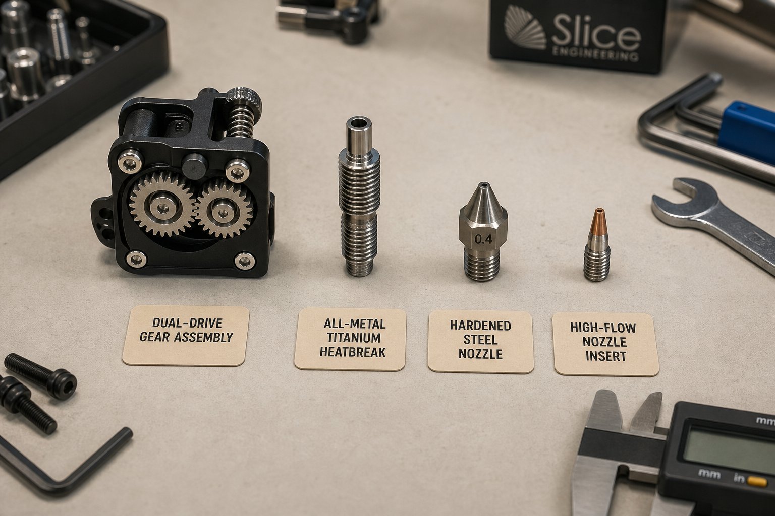
Upgrading Extruder Parts for Performance and Reliability
Not every upgrade delivers equal results. Swapping in a flashy new component without understanding the bottleneck it's supposed to relieve is how hobbyists end up with a drawer full of unused hardware and prints that look exactly the same as before. The best 3D printer extruder upgrades share a common trait — they remove a specific limitation that stock parts impose on speed, filament range, or consistency. Knowing which limitation you're hitting tells you exactly where your money is best spent.
Top Upgrades for Speed and Filament Versatility
Some changes are transformative. Others are marginal. Here's a practical ranking based on how much real-world improvement each 3D printer extruder upgrade delivers, paired with the effort required to install and tune it.
- High impact, moderate difficulty — All-metal heatbreak: Replacing a PTFE-lined heatbreak with an all-metal version is the single most consequential upgrade for filament versatility. PTFE degrades above 240-260°C, which locks out engineering-grade materials like nylon, polycarbonate, and ASA. An all-metal titanium or stainless steel heatbreak eliminates that temperature ceiling entirely. The tradeoff is a slightly higher tendency toward heat creep with PLA at lower temperatures, which usually requires tuning retraction settings and ensuring your heatsink fan runs at full speed. For anyone who wants to move beyond basic PLA and PETG, this upgrade is essential.
- High impact, low difficulty — Dual-drive gear system: If your printer ships with a single drive gear and a smooth idler bearing, switching to a dual-gear system is one of the easiest and most noticeable improvements you can make. Dual gears grip filament from both sides, distributing force evenly and dramatically reducing slippage — especially with flexible filaments like TPU, softer PETG blends, and any material that tends to compress under one-sided pressure. Kits like the Bondtech BMG offer drop-in dual-drive upgrades compatible with many popular printer frames. Expect more consistent extrusion, less filament grinding, and fewer mid-print feed failures.
- High impact, low difficulty — Hardened or specialty nozzle: Covered in detail earlier, but worth emphasizing as an upgrade: moving from a stock brass nozzle to hardened steel, tungsten carbide, or a ruby-tipped variant unlocks abrasive composite filaments — carbon fiber, glass fiber, metal fill — without the rapid bore erosion that destroys a brass tip in hours. This is less of a performance upgrade and more of a capability expansion. If you ever plan to print filled materials, install a hardened nozzle before your first spool, not after you've already widened the brass bore beyond tolerance.
- Moderate impact, moderate difficulty — High-flow nozzle design: Standard V6-class hotends top out near 10 to 15 mm³/s of volumetric flow before under-extrusion appears. High-flow nozzle inserts — such as the Bondtech CHT with its three-channel core — push that ceiling to roughly 30-40 mm³/s by splitting the incoming filament into multiple thinner streams that melt faster. Paired with a high-speed PLA or PETG, these nozzles let modern CoreXY machines actually sustain the 200-300 mm/s print speeds their motion systems are capable of. Without a high-flow nozzle, even a 600 mm/s-rated printer stalls at the melt zone bottleneck. Note that high-flow printing also demands a higher-wattage heater cartridge — typically 50W or greater — to keep up with the increased thermal demand.
- Moderate impact, low difficulty — Premium PTFE tube (Bowden systems): For Bowden setups, replacing the stock PTFE tube with a tighter-tolerance premium version reduces internal friction, minimizes filament wobble, and raises the safe operating temperature by 10-20°C. This is a low-cost upgrade with an outsized effect on retraction performance and feed consistency across the long filament path.
- Lower impact, higher difficulty — Lightweight extruder housing or carriage plate: Reducing moving mass through CNC-machined aluminum housings or magnesium carriage plates allows higher accelerations without ringing — but the improvement is marginal unless you're already pushing above 3,000 mm/s² and have input shaping tuned. This is a fine-tuning upgrade for experienced users chasing the last 10-15% of speed, not a first-priority improvement.
A filament extruder for 3D printer work is only as capable as its weakest component. The upgrades above follow a logical sequence: first expand your temperature range (all-metal heatbreak), then improve your feed reliability (dual gears), then broaden your material compatibility (hardened nozzle), and finally unlock speed (high-flow nozzle plus adequate heater wattage). Jumping straight to a high-flow nozzle while still running a PTFE-lined heatbreak and single-gear feeder is like installing a turbocharger on a car with bald tires — the bottleneck simply moves to the next weakest link.
Sourcing Reliable Custom and OEM-Equivalent Parts
Consumer desktop printers benefit from a massive aftermarket ecosystem. Finding a replacement nozzle, heatbreak, or drive gear for a Creality Ender 3 or a Bambu Lab X1 Carbon takes about thirty seconds online. But step outside the consumer mainstream — into industrial extrusion equipment, legacy printer models, or specialized machines — and the parts landscape changes dramatically.
Imagine you're maintaining a production-line extruder where a screw tip has worn past tolerance, or a heater band has failed on a machine model that the original manufacturer discontinued three years ago. The OEM catalog lists the part as "no longer available." Generic aftermarket listings don't match the thread pitch, bore diameter, or wattage. You're staring at a custom extruder component that simply doesn't exist in any standard catalog — and every hour the machine sits idle costs real money.
This is where custom-manufactured components become not just convenient but necessary. A growing number of suppliers specialize in fabricating extruder parts from technical drawings, physical samples, or measured dimensions — producing components that match original specifications exactly when off-the-shelf options fall short. For maintenance teams and plant buyers sourcing items like screw tips, check rings, injection nozzles, heater bands, thermocouples, die heads, and gearbox-related components, NANHAIYA's extruder spare parts catalog serves as a practical resource. Their approach centers on manufacturing to specification — whether from a drawing, a worn sample that needs replication, or measured dimensions from the original component — covering the gap that standard catalogs leave open for less common or discontinued machine models.
Whether you're upgrading a desktop printer with off-the-shelf components or sourcing precision-machined replacements for industrial equipment, the principle is the same: verify specifications before ordering, confirm material compatibility with your operating conditions, and test the new component under controlled conditions before committing it to a production run. The best upgrade is one that drops in cleanly, performs reliably from the first cycle, and doesn't introduce the kind of installation errors covered in the previous section.
Upgrades extend what your machine can do. But even the highest-quality components have finite lifespans — and knowing exactly when to inspect, service, and replace each one is what separates printers that run reliably for years from machines that lurch from one emergency repair to the next.
Maintenance Schedules and Building a Spare Parts Inventory
Knowing that your nozzle will eventually wear or your PTFE tube will degrade is useful. Knowing when — in approximate print hours — to check each component before it fails is what actually keeps your printer running. Yet most users operate without any maintenance schedule at all, treating every component as "fine until it breaks." That reactive approach virtually guarantees that your first warning sign is a ruined print rather than a two-minute visual inspection that catches the problem early.
A structured, usage-based inspection routine turns random failures into predictable maintenance events. Whether you're running a single desktop 3D extruder or managing a fleet of production machines, the intervals below give you a practical framework calibrated to real-world wear rates — not guesswork.
Inspection Intervals by Component and Usage Level
The inspection intervals listed here are based on standard-use conditions: primarily PLA and PETG filaments, typical print speeds of 40 to 80 mm/s, and nozzle temperatures below 240°C. If you're printing abrasive composites like carbon fiber or glass-filled nylon, treat every nozzle and drive gear interval as roughly half the listed value — those materials accelerate wear dramatically.
Prusa Research recommends inspecting and maintaining key printer components every 200 to 300 hours of print time. That cadence serves as a solid baseline, but individual extruder parts wear at different rates depending on their function and exposure. The table below breaks this down component by component, so you can focus your inspection time where it matters most at each service interval.
| Part Name | Inspection Interval (Print Hours) | Typical Replacement Interval | Key Inspection Action |
|---|---|---|---|
| Brass Nozzle | Every 200-400 hours | 400-800 hours (non-abrasive filament) | View orifice from below for roundness; print single-wall test to measure actual extrusion width against expected diameter |
| Hardened/Specialty Nozzle | Every 500-800 hours | 2,000+ hours | Same visual and dimensional check as brass; inspect for tip deformation from bed contact |
| PTFE Tube | Every 300-500 hours (or immediately if printing above 230°C regularly) | 500-1,000 hours | Remove and inspect for discoloration, inner diameter enlargement, and deformed or mushroomed ends at fittings |
| Drive Gear(s) | Every 500+ hours, or whenever filament grinding appears | 1,000-2,000+ hours | Check tooth sharpness with magnification; clean filament debris from grooves with compressed air or a brass brush |
| Idler Bearing | Every 500 hours | 1,500-3,000 hours | Spin by hand to confirm smooth, quiet rotation; replace if rough or seized |
| Heater Cartridge | Every 500 hours (check wiring and fit) | 2,000-5,000 hours | Confirm snug fit in heat block bore with no wobble; inspect wiring insulation for burn marks, fraying, or cracking |
| Thermistor | Every 500 hours (check wiring and seating) | 2,000-5,000 hours | Verify seated position in bore; check for exposed wire, kinks, or intermittent temperature readings during heat-up |
| Heatbreak | During any full hotend disassembly | 2,000-5,000+ hours (unless clogged or damaged) | Shine a light through the bore to check for residue buildup or narrowing; inspect threads for deformation |
| Heatsink Fan | Every 200-300 hours | 3,000-8,000 hours | Confirm full speed spin; clear dust and plastic threads from blades; listen for bearing noise |
| Pneumatic Couplers (Bowden only) | Every 300-500 hours | 500-1,500 hours | Tug the PTFE tube gently while the coupler is locked; any slippage means the internal teeth are worn |
A few practical notes on using this table. First, print hours are cumulative — they don't reset when you change filament spools or swap between materials. Most modern printers track total runtime in their firmware menu, and some slicer software estimates job hours, making it relatively straightforward to keep a running total. Second, if you use multiple printers — whether that's a pair of desktop machines or a farm of a dozen — track each machine independently. A heavily used machine running two shifts daily accumulates 500 hours in roughly six weeks, while a lightly used hobbyist printer might take six months to reach the same milestone.
These intervals also apply broadly across popular consumer platforms. Whether you're maintaining makerbot parts on an older Replicator, servicing the toolhead on a newer CoreXY machine, or keeping a budget FLSUN T1 Pro extruder in top shape, the underlying wear mechanisms — abrasion on gear teeth, thermal degradation of PTFE, bore erosion on nozzles — follow the same physics regardless of brand. Adjust the intervals for your specific usage patterns, and you'll have a schedule that catches problems before they cascade into failed prints.
Building a Spare Parts Kit for Minimal Downtime
Inspection schedules tell you when to look. A well-stocked spare parts kit ensures that when you find something worn, you can replace it in minutes instead of waiting days for a shipment. The goal isn't to stockpile an entire second printer — it's to keep the consumable, high-wear components on hand so that a routine maintenance session never turns into unplanned downtime.
For a typical desktop 3D printer operator, a practical spare parts kit includes:
- Two to three nozzles in your most-used size and material — if you print primarily PLA on a 0.4mm brass nozzle, keep two spares; if you regularly run abrasive filaments, stock hardened steel or tungsten carbide replacements instead
- One spare PTFE tube pre-cut to the correct length for your printer, with clean, square ends — having this ready eliminates the most common delay during a Bowden tube swap
- One replacement thermistor matched to your firmware's sensor type (NTC 100K or PT1000 — verify before purchasing)
- One replacement heater cartridge matched to your heat block's bore diameter and the correct wattage rating for your setup
- A spare set of drive gear hardware — including the primary gear, idler bearing, and tensioner spring if applicable
- Pneumatic couplers (Bowden systems only) — these small fittings are the most frequent failure point in the Bowden filament path and cost under a dollar each
This kit fits in a small parts box and represents perhaps $15 to $40 in total investment — a trivial cost compared to the filament, electricity, and time wasted on a single failed multi-hour print caused by a component you could have swapped in five minutes.
For users who also operate recycling or filament-production equipment — such as a filabot filament extruder for converting scrap plastic back into usable spools, or a filabot reclaimer for grinding failed prints into pellets — the same spare-parts philosophy applies to those machines as well. Drive components, heating elements, and thermal sensors in any extrusion system follow similar wear curves, and keeping spares on hand for the filabot filament maker or similar pellet-to-filament systems prevents bottlenecks in your material recycling workflow just as effectively as it prevents bottlenecks in your printer fleet.
The calculus shifts significantly in industrial and production environments. When a single hour of machine downtime costs hundreds or thousands of dollars, the value of pre-sourced replacement components is measured not in convenience but in direct financial impact. Production facilities running large-format or specialized extrusion equipment face an additional challenge: many of the components they need — screw tips, check rings, heater bands, die heads, pelletizing blades, screen packs, and filter adapters — are either discontinued by the original manufacturer or never had a standard aftermarket equivalent in the first place.
For these scenarios, suppliers who manufacture to specification become indispensable. NANHAIYA's extruder spare parts catalog supports maintenance teams and plant buyers by producing components based on technical drawings, physical samples, or measured dimensions from the original part — covering everything from thermocouples and gearbox components to custom-profiled die heads. The ability to order exact-specification replacements in advance and keep them in inventory means that when a scheduled inspection reveals a worn component, the swap happens during planned maintenance rather than triggering an emergency procurement cycle that idles the machine for days or weeks.
Whether your operation is a single desktop printer on a workbench or a facility with dozens of industrial extruders running around the clock, the underlying strategy is identical: inspect on a schedule, stock the parts that wear, and replace components proactively based on measured condition rather than catastrophic failure. The table and kit list above give you the framework. Adapt the intervals to your materials and usage intensity, build your kit before you need it, and you'll spend far less time troubleshooting and far more time printing.
A proactive maintenance schedule combined with a well-stocked spare parts kit is the most cost-effective strategy for consistent extrusion quality — the cost of a few spare nozzles and a thermistor on the shelf is always less than the cost of a failed production run and the downtime to diagnose it.
Frequently Asked Questions About Extruder Parts
1. What are the main parts of a 3D printer extruder?
A 3D printer extruder consists of three functional systems working together. The feeding mechanism includes drive gears, an idler bearing, and a stepper motor that grip and advance the filament. The thermal system contains a heatsink, heatbreak, heat block, heater cartridge, and thermistor — all responsible for melting filament at precisely the right location. The deposition system centers on the nozzle, which shapes molten plastic into a consistent bead at a specific diameter. Each part operates within tight tolerances, and a failure in any single component can cascade through the entire system, causing under-extrusion, clogs, or poor layer adhesion.
2. How often should I replace my 3D printer nozzle and other extruder parts?
Replacement intervals depend on your filament type and print volume. A standard brass nozzle typically lasts 400 to 800 print hours with non-abrasive filaments like PLA and PETG, but may wear out within just a few prints when using carbon fiber or glass-filled composites. PTFE tubes should be inspected every 300 to 500 hours and replaced when discolored or internally enlarged. Drive gears can last 1,000 to 2,000 hours under normal conditions, while heater cartridges and thermistors often survive 2,000 to 5,000 hours. If you regularly use abrasive materials, cut nozzle and drive gear inspection intervals roughly in half.
3. What is the difference between Bowden and direct drive extruder systems?
The core difference is where the drive motor sits relative to the hotend. In a direct drive system, the motor and drive gears mount directly on the print head, keeping the filament path extremely short (under 40mm). This allows precise retraction control (0.5-1.5mm), excellent flexible filament handling, and fast response times. A Bowden system mounts the motor on the printer frame and routes filament through a long PTFE tube (300-600mm) to the hotend. This reduces moving mass for faster accelerations but requires longer retraction distances (4-7mm) and struggles with soft flexible materials. Each architecture uses unique parts — Bowden systems need pneumatic couplers and long PTFE tubes, while direct drive setups rely on compact stepper motors and lightweight housings.
4. Why does my extruder keep grinding filament instead of feeding it?
Filament grinding at the drive gear is usually a symptom of a downstream blockage rather than a gear problem. When a partial clog in the nozzle, a swollen heatbreak, or a deformed PTFE tube creates back-pressure, the drive gear keeps spinning against filament that cannot advance — shaving plastic dust instead of pushing it forward. Before replacing the gear, check for obstructions in the hotend: inspect the nozzle for bore widening, pull filament out to look for a bulged tip indicating heat creep, and verify that the PTFE tube has no internal narrowing or deformed ends. If the gear teeth are visibly rounded or polished smooth, the gear itself may also need replacement, but always rule out downstream causes first.
5. How do I properly install a replacement nozzle without causing leaks or clogs?
The most critical step is hot-tightening the nozzle against the heatbreak inside the heat block — not against the block face itself. Thread the nozzle in finger-tight, then back it off a quarter turn. Install the heatbreak from the top until it contacts the nozzle internally. Heat the hotend to at least 200 degrees Celsius, then use a wrench to give the nozzle a final quarter to half turn of tightening while hot. Thermal expansion at temperature seals micro-gaps that exist when cold. If the nozzle sits perfectly flush with the block bottom, it has bottomed out against the block rather than the heatbreak, leaving an internal gap where molten plastic will pool, carbonize, and cause persistent clogs. Always start threading by hand to avoid cross-threading the soft aluminum block, and never remove or install a nozzle at room temperature.
Written by
Nanhaiya Technical Team
Zhoushan Nanhaiya Plastic Machinery Co., Ltd.
The Nanhaiya technical team supports screw and barrel manufacturing projects through application review, technical communication, custom manufacturing coordination, and production and quality control.
Discuss Your Application
Related Articles
More insights on screw barrel technology and plastics processing.

What Nobody Tells You About Screw Barrel For Plastic Machine Design
Oct 10, 2026
Learn how screw barrel for plastic machine design affects melt quality, throughput, and wear life. Covers geometry, resin matching, troubleshooting, and sourcing.
Read Article
Single Screw Extruder for Sheet: Stop Guessing, Start Specifying
Oct 9, 2026
Learn how to specify a single screw extruder for sheet production. Covers screw geometry, resin-specific processing, troubleshooting, and maintenance best practices.
Read Article
PE Pipe Extruder Machine: What Datasheets Won't Tell You
Oct 9, 2026
Learn how a PE pipe extruder machine works, key specs explained, material grade selection, maintenance tips, and buyer guidance beyond the datasheet.
Read ArticleLooking for something else?
Search by material, symptom or product and jump straight to the relevant page.
These are navigation suggestions based on keyword matching — not a quotation, not a delivery commitment, and not a substitute for engineering review. Final specification is confirmed by our engineers against your drawings and processed material.
Need help with screw barrel selection?
Share your machine model, processed material and application. Our team can help with pricing and technical support.