

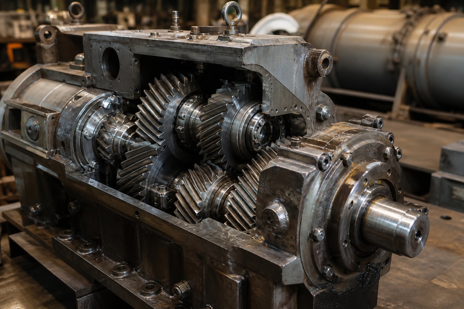
What Is an Extruder Gearbox and Why It Matters
An extruder gearbox is a speed-reduction and torque-multiplication unit positioned between the drive motor and the extruder screw. It converts high-speed, low-torque motor output into the low-speed, high-torque rotation needed to push polymer melt through a barrel and die. In any extrusion line — whether producing pipe, film, sheet, cable, or profiles — this single component sits at the mechanical core of the entire operation, and its condition determines whether your line runs profitably or bleeds money through scrap, downtime, and quality failures.
Why is it also one of the most expensive components on the floor? Because it is precision-engineered to perform under a punishing combination of loads that few other industrial gearboxes ever face. Replace one, and you will quickly understand the cost. Ignore one, and you will understand it even faster.
What an Extruder Gearbox Actually Does
Imagine your drive motor spinning at 1,480 RPM. Your extruder screw, depending on diameter and material, needs to rotate somewhere between 15 and 150 RPM. That gap is the gearbox's job. Through a calculated sequence of helical gear stages, the gearbox for extruder applications reduces speed by a fixed gear ratio — say, 30:1 — and multiplies torque by roughly the same factor, minus small efficiency losses of about 1 to 2 percent per stage.
The fundamental relationship is straightforward: at constant power, halving the speed doubles the torque. A 30:1 ratio reduces motor speed by 30 times and amplifies torque by approximately 30 times. This is how the motor's relatively modest rotational force becomes the enormous turning power required to drive viscous plastic melt forward against barrel pressures that can reach 200 to 700 bar.
But torque multiplication is only part of the story. What makes an extrusion gearbox unique — and far more demanding than a standard industrial reducer — is the combination of three simultaneous load types it must handle:
- Torsional loads from the resistance of the polymer melt against the screw flights
- Radial loads generated by the helical gear mesh forces acting on the shafts and bearings
- Axial (thrust) loads created by Newton's third law — as the screw pushes melt forward toward the die, an equal and opposite reaction force drives back along the screw axis into the gearbox, sometimes exceeding 500 kilonewtons in large extruders processing rigid PVC or HDPE
The thrust bearing assembly inside the gearbox absorbs this massive axial force continuously — not for minutes, but for days and weeks of uninterrupted production. No standard industrial gearbox is designed for this duty. It is this thrust-load requirement that separates a true extruder gearbox from a general-purpose speed reducer, and it is often the first component to fail when a gearbox is underrated for its application.
Why the Gearbox Is the Heart of the Extrusion Line
You might think of the screw and barrel as the heart of extrusion, but every beat of that heart depends on what the gearbox delivers. Gear-ratio precision governs screw speed consistency. Screw speed consistency controls melt pressure stability. And melt pressure stability determines dimensional accuracy and surface finish in your final product — wall-thickness uniformity in pipe, gauge consistency in film, profile tolerances in window frames.
When gear teeth wear and backlash increases, micro-speed fluctuations ripple through the screw rotation. Those fluctuations create melt-pressure surges that show up as dimensional variation your QC team may initially blame on the screw, the barrel, or the resin. When bearings degrade, vibration enters the system and can produce visible surface defects that look like material issues. The gearbox is, in effect, the invisible hand behind your product quality — and when it starts to slip, you'll notice the symptoms everywhere except where they originate.
A failing extruder gearbox rarely stops production instantly — it degrades product quality gradually until the problem becomes catastrophic.
That slow degradation is exactly what makes gearbox problems so costly. By the time operators hear unusual noise or maintenance spots metal particles in the oil, weeks or months of marginal product quality may have already passed. Understanding how this component works — and how it connects to every other system on the line — is the first step toward catching problems before they cascade.
How the Extruder Gearbox Fits Into the Extrusion Line
Most technical resources describe the extruder gearbox as a standalone component — a box with gears, bearings, and oil. That perspective misses the bigger picture. In practice, the gearbox is one node in a tightly interconnected power transmission chain, and every interface it shares with neighboring systems affects reliability, product quality, and process control. Understanding these connections turns a maintenance team from reactive firefighters into engineers who can diagnose root causes before they escalate.
The Power Transmission Chain From Motor to Screw
Trace the energy path from wall power to finished product, and you'll cross six critical interface points — each one engineered to manage a specific set of mechanical forces.
It starts at the electric motor, which converts electrical energy into high-speed rotational power, typically spinning at 960 to 1,480 RPM depending on pole count and supply frequency. That motor shaft connects to the gearbox input shaft through a flexible coupling — and this coupling does far more than simply bolt two shafts together. It isolates the gearbox from motor vibration, compensates for minor angular and parallel misalignment between motor and gearbox shafts, and absorbs torsional shock loads during startup and process disturbances. Without a properly rated coupling, motor vibration transmits directly into the gear train, accelerating bearing wear and gear-tooth fatigue.
From the coupling, energy enters the gearbox input shaft, which carries the first-stage drive pinion — the smallest, fastest gear in the entire assembly. This pinion meshes with a larger wheel gear on an intermediate shaft, completing the first stage of speed reduction and torque multiplication. In a two-stage gearbox, one intermediate shaft carries both a driven wheel and a second driving pinion; in a three-stage unit, two intermediate shafts step the speed down progressively. Each extrusion gear stage reduces speed by a factor of roughly 3:1 to 8:1 while amplifying torque by the same ratio, minus small frictional losses.
The final gear stage delivers power to the output shaft — the most heavily loaded component in the entire drivetrain. This shaft simultaneously carries the maximum output torque, supports the large output wheel gear, and reacts against the full axial thrust force generated by screw pressure. The extruder gearbox thrust bearing assembly, mounted on this shaft, absorbs that continuous axial load so it never reaches the motor bearings, which are not designed for thrust duty.
At the exposed end of the output shaft, a precision-machined bore or spline connects to the screw shank. Dimensional accuracy at this interface is critical — any runout or misalignment here amplifies through the full length of the screw, causing uneven barrel wear and vibration that degrades extrudate quality. The output shaft effectively sets the rotational precision for everything downstream.
In some installations, a belt sheave drive sits between the motor and gearbox input shaft, providing an additional speed adjustment. Changing sheave ratios can increase torque to the screw or boost maximum screw speed — but altering the belt ratio changes the torque loading on both the input and output shafts, potentially reducing gearbox service life if the OEM's torque limits are exceeded.
How the Gearbox Interfaces With Controls and Instrumentation
The extruder gearbox is not just a mechanical device — it is also a data source. Modern extrusion control systems rely on feedback signals from sensors mounted on or near the gearbox housing to maintain process stability, trigger maintenance alerts, and protect equipment from catastrophic damage.
Vibration sensors (accelerometers) are the frontline of predictive maintenance for extruder drives. Mounted at multiple points on the gearbox housing — typically one per bearing position — each sensor measures vibration amplitude at specific frequency bands corresponding to individual gears and bearings. Coperion, for example, equips its ZSK twin-screw extruder gearboxes with accelerometers at several bearing positions, allowing operators to visualize the condition of every gearbox bearing and gauge overall health at a glance through the extruder control interface. When vibration amplitude at gear-mesh frequencies trends upward, the system warns operators well before a bearing or gear tooth reaches failure.
Temperature probes in the oil sump and bearing housings track thermal behavior in real time. A gradual rise in oil temperature under the same load conditions signals increasing internal friction — often the earliest indicator of bearing degradation or lubricant breakdown. Many control systems are configured to trigger alarms when sump temperature exceeds a preset threshold (typically 80 degrees Celsius for mineral oil) and initiate automatic motor shutdown if temperature climbs to a critical level.
Oil condition sensors — flow-type devices installed in the lubrication circuit — continuously measure oil quality parameters such as particle contamination, moisture content, and viscosity change. These sensors detect lubricant degradation between scheduled oil analysis intervals, closing the gap between laboratory sampling events.
Pressure transducers mounted on the barrel side, just downstream of the gearbox-to-barrel interface, measure melt pressure. While not mounted on the gearbox itself, melt pressure data directly reflects gearbox output behavior: micro-speed fluctuations from worn gears or degraded bearings show up as pressure oscillations that the control system can correlate with vibration trends.
Together, these signals feed into the extrusion line's control architecture — whether a standalone PLC, a distributed control system, or an OEM-specific platform. The control system uses them to adjust motor speed in real time, log trend data for predictive maintenance analysis, trigger graded alarm levels, or command emergency shutdowns when parameters exceed safe limits.
Here are the key interface points where the extruder gearbox connects to neighboring systems — each one a potential source of valuable diagnostic data and a maintenance checkpoint:
- Motor-side coupling — transmits torque, isolates vibration, accommodates misalignment
- Thrust bearing assembly — absorbs axial screw forces, prevents thrust from reaching the motor
- Output shaft connection — precision interface to the screw shank, sets rotational accuracy
- Oil circulation system — delivers clean, cooled lubricant to all gear meshes and bearings
- Vibration monitoring ports — accelerometer mounting points at each bearing position
- Temperature sensor ports — probes in the oil sump, bearing housings, and cooling circuit
When you view the extruder gearbox as part of this interconnected system — not as an isolated box of gears — troubleshooting becomes far more effective. A vibration spike correlated with a temperature rise and a melt-pressure oscillation tells a completely different story than any one of those signals in isolation. That systems perspective is what separates reactive maintenance from the kind of predictive strategy that catches failures early, long before they damage gears, bearings, or your product quality.
Types of Extruder Gearboxes Compared
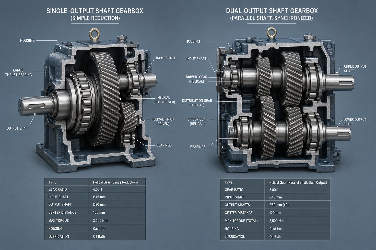
Every interface point described above — the coupling, the thrust bearing assembly, the output shaft connection — is engineered differently depending on whether the gearbox drives a single screw or a pair of synchronized screws. That distinction is not just a matter of adding a second output shaft. It fundamentally reshapes the gear train architecture, the load distribution strategy, and the maintenance considerations that plant teams need to understand. Yet most resources lump all extruder gearboxes into one category or mention the difference in passing without explaining what it means for your operation.
Here is the structured comparison that fills that gap.
Single-Screw vs. Twin-Screw Extruder Gearbox Design
A single-screw extruder gearbox manages one output shaft. Its primary engineering challenge is handling extremely high axial thrust loads — the reaction force generated as the screw pushes melt toward the die. Because only one screw is involved, the thrust bearing assembly can be sized generously within the housing, and the gear train follows a straightforward parallel-shaft or offset layout with two or three reduction stages. Design complexity is moderate, reliability is high, and maintenance intervals tend to be forgiving.
A twin-screw extruder gearbox is a fundamentally different machine. Two parallel output shafts must rotate at precisely the same speed and maintain exact angular timing — either co-rotating (both shafts turning in the same direction) or counter-rotating (shafts turning in opposite directions). This synchronization requirement demands a distribution gear stage that splits torque evenly between the two shafts while keeping them phase-locked. The narrow center distance between intermeshing twin screws further constrains bearing size and shaft diameter, concentrating heavy loads into compact spaces.
As Coperion notes, the high dynamic torque required by twin-screw extruders combined with the narrow center distance of the two output shafts causes heavy stresses on shafts, gear meshing, and rolling bearings — making regular overhaul and modernization essential to exploit the full potential of the equipment.
Application suitability follows directly from these design differences. Single-screw gearboxes dominate in profile extrusion, pipe, blown and cast film, sheet, wire and cable coating, and other processes where one screw conveys and melts a relatively uniform feedstock. Twin-screw gearboxes serve compounding, reactive extrusion, devolatilization, and advanced recycling operations where intensive mixing, precise additive dispersion, and degassing of complex or contaminated materials are required.
The table below lays out the key distinctions side by side:
| Comparison Factor | Single-Screw Extruder Gearbox | Twin-Screw Extruder Gearbox |
|---|---|---|
| Design Complexity | Moderate — standard parallel-shaft reduction with 2 or 3 stages | High — requires torque-distribution stage, synchronization gearing, and compact shaft spacing |
| Thrust Load Handling | Single large thrust bearing assembly; generous space for bearing sizing | Two thrust bearing assemblies constrained by narrow center distance; load sharing is critical |
| Typical Gear Ratio Range | 10:1 to 30:1 (varies by screw diameter and application) | 5:1 to 15:1 (lower ratios common due to higher screw speeds in compounding) |
| Primary Applications | Profile, pipe, film, sheet, wire coating, general-purpose extrusion | Compounding, reactive extrusion, devolatilization, recycling, masterbatch production |
| Relative Cost | Lower — simpler gear train, fewer precision components | Higher — complex distribution gearing, tighter manufacturing tolerances, premium materials |
| Maintenance Complexity | Lower — fewer shafts, bearings, and gear meshes to inspect and service | Higher — synchronization gears, dual thrust assemblies, and tight tolerances demand specialized overhaul procedures |
One detail that often surprises engineers new to twin-screw systems is the cost premium driven by the gearbox alone. Twin-screw gearboxes require high-torque, high-precision distribution gearing with extremely complex manufacturing processes, and that complexity cascades through to spare-parts pricing, overhaul costs, and lead times. Knowing this upfront helps plant managers budget realistically — not just for the initial purchase, but for the total lifecycle cost of each gearbox type.
Major Gearbox Brands and Their Market Position
Walk through enough extrusion plants, and you'll see nameplates from a wide range of manufacturers on gearbox housings. Each brand has carved a distinct market position, and understanding those positions helps when evaluating replacement options or sourcing cross-compatible components.
Coperion is widely recognized for its twin-screw compounding gearboxes, particularly those integrated into its ZSK series extruders. The Coperion extruder gearbox is engineered specifically for the high dynamic torque and narrow shaft spacing demanded by co-rotating twin-screw applications. Coperion maintains dedicated gearbox overhaul workshops in Stuttgart and Wytheville, offering full disassembly, inspection, magnetic particle testing, and detailed reporting — a service model built around their proprietary designs. For plants running Coperion gearbox units, these factory overhaul programs provide the deepest expertise on the specific load profiles and design details of their equipment.
Radicon (now part of Elecon Engineering) holds a strong position in industrial-duty reduction gearboxes used across extrusion, rubber processing, and heavy manufacturing. The Radicon gearbox is often specified for single-screw extrusion lines where robust, high-ratio speed reduction and reliable thrust-load absorption are the primary requirements. Their product range covers helical, bevel-helical, and worm gear configurations, with some models purpose-built for extruder applications featuring integrated thrust bearing assemblies.
Other notable OEM suppliers include Flender (a Siemens brand) with a broad portfolio of industrial gearboxes frequently applied in extrusion service, Eisenbeiss (part of the ANDRITZ group) known for high-torque-density extruder gearboxes, and PIV / Brevini (now Dana Incorporated) supplying both standard and custom extruder drive solutions. Regional manufacturers across Europe and Asia also produce competent gearboxes — some as OEM suppliers to extruder builders, others as aftermarket specialists serving the replacement and rebuild market.
Here is the reality that matters most to maintenance teams: many processing plants run extrusion lines equipped with gearboxes from multiple OEMs. A pipe plant might have Flender gearboxes on two lines, a Radicon unit on a third, and a legacy no-name gearbox on a fourth machine acquired years ago. When any of those units needs attention, the ability to source cross-compatible replacement gears, shafts, bearings, thrust assemblies, and seals — regardless of original brand — becomes the deciding factor in repair turnaround time and cost. Brand loyalty matters less than component availability, and that practical truth shapes how experienced plant engineers approach gearbox maintenance and sourcing decisions.
The differences in gearbox design and brand ecosystem also determine how — and how often — things go wrong. Failure modes vary between single-screw and twin-screw units, and knowing what to look for in each type can mean the difference between catching a developing problem early and dealing with a catastrophic breakdown during a production run.
Common Failure Modes and Root Cause Analysis
Every extruder gearbox failure tells a story. The pitting pattern on a gear flank, the spalling track on a bearing race, the fatigue crack radiating from a keyway corner — each one traces back to a specific root cause that was present, detectable, and preventable long before it became a production emergency. The challenge is knowing what to look for and understanding how quickly each failure mode progresses from early symptom to catastrophic event.
What makes extruder gearbox problems particularly treacherous is the operating environment itself. These gearboxes run continuously — often 16 to 24 hours a day, six or seven days a week — under a relentless combination of high torque, heavy axial thrust, and elevated temperatures. That duty cycle accelerates every wear mechanism and shortens the window between "developing issue" and "emergency shutdown."
Mechanical Failure Modes in Extruder Gearboxes
When plant engineers pull apart a failed unit, the damage typically falls into one of four categories: gear tooth failures, bearing failures, shaft failures, and seal failures. Each category has distinct root causes, distinct early warning signs, and a distinct progression timeline that determines how much time you have to act.
Gear tooth failures are the most common long-term degradation mechanism. They begin with surface contact fatigue — every mesh cycle generates intense Hertzian contact stress at the tooth flank, and over millions of cycles, subsurface cracks initiate and propagate upward. The visible result is pitting: small, hemispherical craters that first appear as a matte, grey-frosted texture (micropitting) and gradually coalesce into larger, destructive pits called spalling. Left unchecked, spalling removes enough tooth material to increase backlash, reduce load-carrying capacity, and eventually trigger tooth fracture. The progression from initial micropitting to destructive spalling typically spans months to years under normal loading — but inadequate lubrication or chronic overloading can compress that timeline dramatically.
Scuffing is a different beast entirely. Where pitting is slow and progressive, scuffing is rapid and self-accelerating. It occurs when the lubricating oil film between meshing teeth collapses completely, allowing direct metal-to-metal contact at high sliding velocity. The asperities of the two surfaces momentarily weld together through adhesion, and as the gears continue rotating, these micro-welds tear apart — ripping material from one or both flanks. Scuffing generates extreme local heat, which further degrades the oil film and accelerates the process. A gearbox can go from onset of scuffing to severe tooth destruction in minutes if not stopped. Cold startups under load, wrong oil viscosity, and cooling system failures are the most common triggers in extrusion applications.
Tooth breakage — bending fatigue fracture at the tooth root — is the most dramatic failure mode. Each tooth acts as a cantilevered beam loaded at its tip, and the root fillet zone sees maximum bending stress with every engagement. When operating loads exceed the material's fatigue limit — through chronic overloading, repeated cold-start shock loads, or material defects — a fatigue crack initiates at the root and propagates slowly through 70 to 90 percent of the cross-section before the remaining material fractures suddenly. The result is immediate, often catastrophic: tooth fragments can cascade through the gear train, damaging every mesh they contact.
Bearing failures rank as the second most frequent cause of extruder gearbox damage. The same contact fatigue mechanism that pits gear teeth also attacks bearing raceways — cyclic stress at each rolling contact eventually initiates subsurface cracks that propagate to the surface, producing raceway spalling. Brinelling — static indentation damage from shock loads or vibration during non-operating periods — creates dents in the raceway that act as stress concentrators, accelerating subsequent fatigue. Cage failure, where the bearing retainer cracks or deforms, releases rolling elements from their controlled spacing and can cause sudden, complete bearing collapse.
Thrust bearing failure deserves special attention in extrusion service. This bearing absorbs the entire axial reaction force from the screw — loads that can reach several hundred kilonewtons continuously in large extruders. When it fails, the output shaft loses axial positioning, and the screw can shift forward into the barrel bore, destroying both the screw and barrel — components far more expensive than the bearing itself.
Shaft failures are rare but dramatic. Fatigue cracks initiate at stress concentrations — keyway corners, shoulder fillets, surface defects, or corrosion pits — and grow progressively under cyclic bending and torsional loads until the remaining cross-section can no longer carry the load. Correct keyway design with adequate fillet radii, precise shaft alignment to minimize cyclic bending, and protecting shaft surfaces from corrosion are the primary defenses.
Seal failures are the most frequently observed maintenance issue by occurrence count. While rarely immediately catastrophic, a failed shaft seal has two simultaneous consequences: oil leaks out, and contaminants leak in. The oil loss is visible and obvious. The contaminant ingress — plastic dust, glass fiber particles, moisture — is the hidden, far more damaging outcome. Fine abrasive particles from a failed seal can trigger accelerated gear pitting and bearing wear within 12 to 24 months of seal failure.
Ranked by frequency as generally observed in extrusion maintenance practice, the most common failure modes are:
- Seal degradation and oil leakage — the most frequent maintenance event, often initiating a cascade of secondary damage through contaminant ingress and oil starvation
- Gear tooth surface pitting and spalling — the most prevalent long-term gear degradation mode, driven by contact fatigue and accelerated by lubrication breakdown
- Rolling bearing fatigue and raceway spalling — second most common cause of major gearbox damage, detectable through vibration monitoring weeks before audible symptoms appear
- Thrust bearing failure — less frequent but uniquely catastrophic due to potential screw-to-barrel contact and secondary component destruction
- Gear tooth scuffing — rapid-onset adhesive wear from oil film collapse, often triggered by cold startups, wrong oil grade, or cooling system failure
- Shaft fatigue fracture — the rarest mode, but the most dramatic, typically originating at keyway stress concentrations or corrosion pits
How Gearbox Degradation Impacts Product Quality
Here is the connection that most maintenance teams and quality departments miss entirely: your extruder gearbox condition is directly linked to your extrudate quality — and the symptoms of gearbox degradation often masquerade as completely different problems.
Picture this scenario. Your pipe line starts producing wall-thickness variations that exceed tolerance. The quality team checks resin lot consistency. The process engineer reviews screw and barrel wear measurements. The maintenance crew inspects the die and calibration tooling. Everyone looks at the obvious suspects, and nobody thinks to examine the gearbox — because it is still running, still quiet enough, and still making product.
But increased gear backlash from progressive tooth wear causes micro-speed fluctuations in screw rotation. Those fluctuations may amount to fractions of an RPM — imperceptible on a tachometer display — yet they generate melt-pressure surges of several bar inside the barrel. In pipe extrusion, those surges manifest as wall-thickness oscillations. In blown film, they show up as gauge bands — periodic thickness variations that repeat at intervals corresponding to the screw rotation cycle. In profile extrusion, they produce dimensional drift that defies conventional process adjustments.
Bearing wear introduces a different quality defect pathway. As bearing surfaces degrade, vibration amplitude increases at specific frequencies — frequencies that transmit through the output shaft and into the screw. That vibration can produce visible surface defects on the extrudate: roughness, streaking, or matte patches that look like material degradation or die lip contamination. An infrared camera pointed at the gearbox housing during production may reveal hot spots at worn bearing positions, but without that intentional check, the vibration-driven surface defects get attributed to material problems, die wear, or melt temperature instability.
Gearbox-related quality issues are frequently misdiagnosed as screw and barrel wear or material problems — costing plants weeks of troubleshooting and unnecessary component replacements before the true root cause is identified.
The lesson is practical: any time your quality data shows unexplained dimensional variation or surface defects that do not respond to normal process adjustments, add the gearbox to your investigation checklist. A vibration reading at gear-mesh frequency and a quick oil sample for wear-metal analysis can confirm or rule out the gearbox in a single shift — saving your team from chasing phantom causes across the rest of the line.
Catching these failure modes early enough to act is one thing. Preventing them from developing in the first place requires a disciplined approach to two critical systems that most extrusion plants under-manage: lubrication and thermal control.
Lubrication and Thermal Management Best Practices
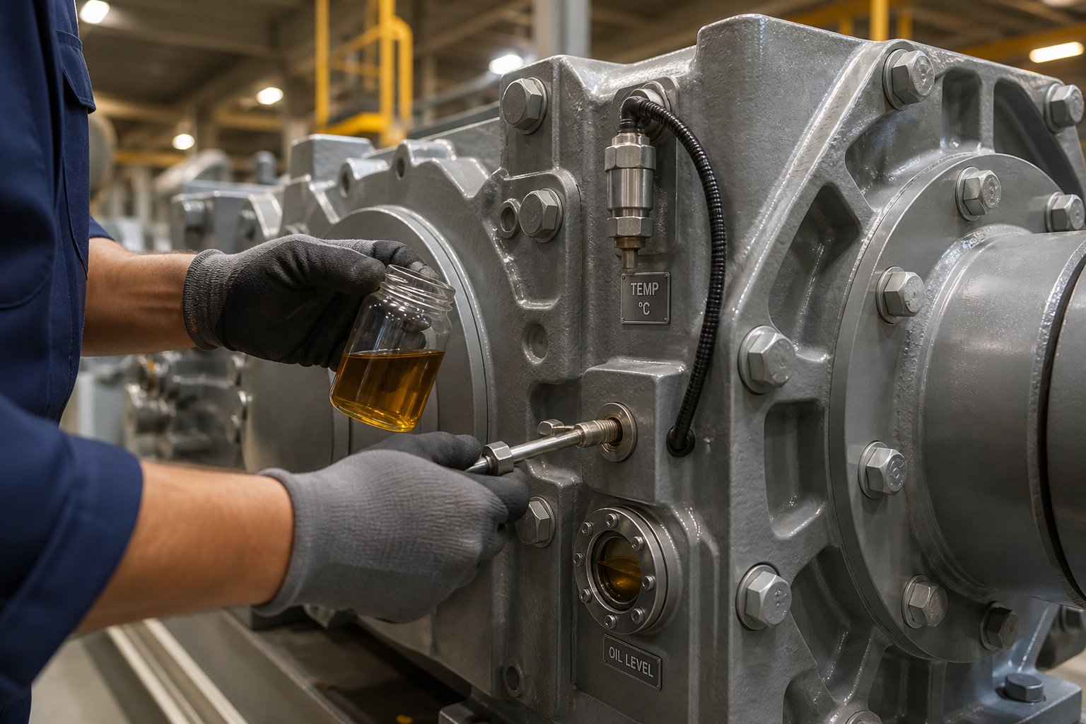
Lubrication failure and extruder gearbox overheating are not just common failure triggers — they are the most common. Every mechanical failure mode discussed above — pitting, scuffing, bearing spalling, seal degradation — accelerates dramatically when oil quality degrades or operating temperature climbs beyond design limits. Yet walk through most extrusion plants, and you'll find that gearbox oil gets far less attention than barrel heater settings or screw and barrel clearances. That imbalance is costly. Getting lubrication and thermal management right is the single most effective thing a maintenance team can do to extend gearbox service life and prevent surprise failures.
Lubrication Types, Schedules, and Oil Analysis
Choosing the right extruder gearbox oil is not a matter of grabbing whatever gear oil is on the shelf. The lubricant must match the gearbox's operating temperature, load profile, and OEM specifications — and those requirements vary significantly across different extrusion applications.
Three main lubricant categories cover the majority of extruder gearbox installations:
Mineral-based EP (extreme-pressure) gear oils are the most widely specified and most affordable option. EP additives — typically sulphur-phosphorus compounds — form a sacrificial protective layer on gear and bearing surfaces under heavy contact stress, preventing metal-to-metal adhesion and scuffing. These oils work well in standard-duty, moderate-temperature extrusion applications with conventional oil change intervals of roughly 4,000 to 6,000 operating hours (approximately 6 to 12 months of continuous production). ISO VG 220 is the most commonly specified viscosity grade for enclosed helical gearboxes in extrusion service, while ISO VG 320 is used for heavily loaded or slow-speed units operating in higher ambient temperatures.
Synthetic PAO-based (polyalphaolefin) gear oils offer superior performance at both temperature extremes. Their higher viscosity index means the oil maintains better film thickness at elevated temperatures and flows more freely during cold starts — reducing both churning losses and contact friction compared to mineral oils of the same nominal grade. In practice, switching from mineral to synthetic PAO oil of the same viscosity grade can reduce gearbox operating temperature by 5 to 15 degrees Celsius, thanks to lower traction coefficients and improved thermal stability. Synthetic oils also resist oxidation far longer, enabling extended drain intervals of 10,000 to 15,000 operating hours (roughly 2 to 3 years) in well-maintained systems. The higher upfront cost is usually recovered through fewer oil changes and reduced wear-related maintenance.
Polyglycol-based (PAG) lubricants are specified by certain OEMs for particular gearbox designs — especially worm gear units where the sliding contact mechanism generates extreme heat at the mesh. PAG oils have inherently low friction coefficients and excellent thermal conductivity, making them well-suited for high-heat applications. However, they are incompatible with mineral and PAO oils, requiring complete system flush before switching. Always verify the OEM recommendation before using PAG lubricant in any gearbox not explicitly designed for it.
Selecting the correct ISO viscosity grade depends on two primary factors: operating oil temperature and load severity. A gearbox running at 50 to 60 degrees Celsius oil temperature under moderate load may perform optimally on VG 220. The same gearbox operating at 70 to 80 degrees Celsius in a high-ambient plant environment — or handling heavier thrust loads from a high-output screw — may need VG 320 to maintain adequate film thickness. When in doubt, consult the gearbox manufacturer's data sheet; it specifies both the base oil type and the viscosity grade validated for the unit's design loads and temperature range.
| Oil Type | Temperature Range | Typical Applications | Change Interval Guidance | Key Monitoring Parameters |
|---|---|---|---|---|
| Mineral EP (ISO VG 220/320) | 40 - 80 degrees C sump temperature | Standard single-screw extrusion (pipe, profile, film); moderate-duty twin-screw lines | 4,000 - 6,000 operating hours; initial break-in change at 500 hours | Viscosity at 40 degrees C, wear metals (Fe, Cu, Cr), particle count (ISO 4406), water content |
| Synthetic PAO (ISO VG 220/320) | -20 to 100 degrees C sump temperature | High-output lines, high-ambient plants, twin-screw compounders, gearboxes running marginally hot on mineral oil | 10,000 - 15,000 operating hours; initial break-in change at 500 hours | Viscosity at 40 degrees C, oxidation level (FTIR), wear metals (Fe, Cu, Cr), particle count, water content |
| Polyglycol (PAG) | -30 to 120 degrees C sump temperature | Worm gearboxes, specific OEM-mandated applications; must not be mixed with mineral or PAO | Per OEM specification — typically 8,000 - 12,000 operating hours | Viscosity at 40 degrees C, acid number (TAN), water content, wear metals, residue formation |
Lubrication schedule framework. Regardless of oil type, every extruder gearbox should follow a structured oil change schedule anchored to three milestones:
- Break-in change: Replace the initial fill at approximately 500 operating hours. New gears and bearings generate elevated wear particles during the run-in period as surfaces conform under load. Leaving this particle-laden oil in the sump accelerates subsequent wear.
- Routine interval changes: Follow the OEM-specified interval — typically every 4,000 to 6,000 hours for mineral oil, or 10,000 to 15,000 hours for synthetic PAO — as a baseline. Adjust shorter if operating temperatures consistently exceed 75 degrees Celsius, since oil oxidation rate approximately doubles with every 10-degree rise above 60 degrees Celsius.
- Condition-based changes: Use laboratory oil analysis to decide whether to extend or shorten the routine interval. A sample showing stable viscosity, low wear-metal concentrations, and clean particle counts can safely run longer. A sample showing rising iron and copper particles, viscosity drift, or water contamination above 200 ppm demands immediate action — regardless of how many hours remain on the calendar schedule.
Oil analysis as a predictive maintenance tool. Think of used oil as a diagnostic fluid. Every particle, every chemical change it carries records exactly what happened inside the gearbox since the last sample. Industrial gearbox oil analysis typically tracks four categories of information:
- Wear-metal concentrations — Iron (Fe) indicates gear tooth and shaft wear. Copper (Cu) signals bearing cage or bronze thrust washer degradation. Chromium (Cr) points to hardened bearing race or gear surface wear. Rising trends in any of these metals, weeks before any external symptom appears, give maintenance teams time to plan an intervention rather than react to a breakdown.
- Particle count (ISO 4406) — Measures the cleanliness of the oil by counting particles in specific size ranges. A gearbox with a clean, well-sealed oil system should maintain an ISO cleanliness code of 18/15/12 or better. Rising particle counts indicate contamination ingress, seal failure, or accelerating internal wear.
- Viscosity change — An increase in viscosity at 40 degrees Celsius signals oil oxidation and thickening — meaning higher churning losses, more heat generation, and reduced film flow to critical contact zones. A decrease signals fuel dilution, shear breakdown, or contamination with a lighter fluid.
- Water contamination — Even small amounts of water (above 200 ppm) dramatically reduce the oil's load-carrying capacity, accelerate oxidation, and promote corrosion of internal surfaces. In gearboxes with internal water cooling coils, a sudden spike in water content is the earliest warning sign of a coil leak — one of the most damaging failures that can occur in a cooled gearbox.
For most extrusion plants, sampling every 500 to 1,000 operating hours — or quarterly, whichever comes first — provides the right balance between early detection and practical cost. The investment is minimal: a sample bottle, a few minutes of technician time, and a laboratory analysis fee that pales against the cost of a single unplanned gearbox repair.
Cooling Systems and Thermal Management Strategies
Heat is the silent accelerant behind nearly every gearbox failure mode. It thins the oil film, speeds oxidation, softens bearing materials, degrades seals, and shrinks the gap between normal operation and catastrophic lubrication breakdown. Understanding where gearbox heat comes from — and how to remove it efficiently — is essential for any plant running high-output extrusion lines.
Three primary sources generate heat inside the gearbox:
- Gear mesh friction — Even at 97 to 98 percent efficiency per gear stage, the remaining 1 to 2 percent of transmitted power converts to heat at each tooth contact zone. A two-stage helical gearbox transmitting 110 kW at 97 percent efficiency generates approximately 3.3 kW of continuous heat. That number climbs rapidly with lower efficiency or higher power ratings.
- Bearing friction — Rolling resistance and viscous drag at each bearing position contribute to total heat load, especially at the heavily loaded thrust bearing that absorbs the full axial screw force continuously.
- Oil churning and windage — In splash-lubricated gearboxes, rotating gears agitate the oil sump, and the energy consumed by that churning action converts to heat. Higher oil levels and faster gear speeds amplify this effect.
The combined heat load sets the thermal management requirement. For most helical extruder gearboxes in the 55 to 200 kW range, total heat generation falls between 1.5 and 8 kW — modest enough for standard cooling methods. Large compounding gearboxes above 200 kW, or any worm gear unit, generate substantially more heat and require aggressive cooling systems.
Oil cooling methods used in extrusion gearboxes fall into three main categories, each suited to a different thermal load and plant infrastructure:
- Internal water cooling coils — The most common method for medium-sized extruder gearboxes. A copper-nickel or stainless steel coil submerged in the oil sump transfers heat from the hot oil to circulating cooling water. Simple, reliable, and effective for heat loads up to about 20 kW, these coils require minimal maintenance beyond periodic descaling and flow verification. Target a cooling water flow rate of 8 to 20 liters per minute, with a 5 to 7 degree temperature rise across the coil indicating efficient operation.
- Forced-feed systems with external oil coolers — For high-power or high-ambient applications, a dedicated oil pump circulates lubricant through an external shell-and-tube or plate heat exchanger before returning cooled, filtered oil to the gear mesh and bearing positions under pressure. This approach provides the highest cooling capacity (5 to 100+ kW), the best temperature control accuracy (plus or minus 5 degrees Celsius with thermostatic bypass valves), and the added benefit of positive oil delivery to the thrust bearing — which splash lubrication alone may not adequately serve under all conditions.
- Air-cooled heat exchangers — Used where cooling water is unavailable, these fan-driven units force air across a finned oil-to-air exchanger. They handle moderate heat loads (2 to 15 kW) but are vulnerable to fouling by polymer dust and glass fiber particles common in extrusion plants, requiring frequent cleaning to maintain effectiveness.
Temperature monitoring best practices. Oil sump temperature is the single most informative metric for gearbox thermal health. The target operating range for most mineral-oil-lubricated extruder gearboxes is 50 to 70 degrees Celsius. Between 75 and 85 degrees, oil oxidation accelerates significantly — the degradation rate roughly doubles for every 10-degree rise above 60 degrees. Above 90 degrees, immediate investigation and corrective action are required; above 105 degrees, the machine should be stopped to prevent catastrophic lubrication failure.
Install a temperature probe in the oil sump and connect it to the extrusion line's alarm system. Set a warning alarm at 80 degrees Celsius and a critical alarm at 90 degrees. Log temperature continuously and review trend data weekly — a gradual upward drift under the same production conditions is often the earliest detectable sign of cooling system degradation, oil quality decline, or increasing internal friction from developing mechanical wear.
One often-overlooked cause of extruder gearbox overheating has nothing to do with the gearbox itself: proximity to the extruder barrel. Barrel surface temperatures of 180 to 260 degrees Celsius radiate significant heat into the surrounding space. If the gearbox sits too close — less than 200 to 300 mm of air gap — the elevated ambient temperature around the housing reduces the cooling system's effective capacity. Simply shielding the gearbox from barrel radiation or improving local ventilation can drop sump temperatures by several degrees, buying meaningful margin before more expensive cooling upgrades become necessary.
Lubrication and thermal management are, in the end, preventive strategies — things you do before problems appear. The real test of any gearbox care program, though, is whether it extends naturally into a structured preventive maintenance schedule with defined inspection intervals, clear acceptance criteria, and a condition monitoring framework that catches the first whispers of trouble.
Preventive Maintenance Schedules and Checklists
Knowing the right oil type and cooling strategy is only half the equation. Without a disciplined, repeatable schedule that tells every technician exactly what to check — and what "acceptable" looks like — even the best lubrication program falls apart between shifts. The difference between plants that get 15 years out of an extruder gearbox and those replacing units every 6 to 8 years almost always comes down to one thing: whether inspections are systematic or ad hoc.
What follows is a tiered extruder gearbox maintenance framework you can adapt to your specific equipment, operating hours, and criticality level. Print it, pin it to the maintenance board, and treat it as a living document — because consistent execution of these checkpoints is the most cost-effective reliability investment your plant can make.
Inspection Intervals and Key Checkpoints
Effective gearbox preventive maintenance in extrusion follows a frequency-based hierarchy. Daily tasks catch acute problems before they escalate within a single shift. Weekly and monthly checks track gradual changes. Quarterly oil analysis reveals hidden wear trends. And annual internal inspections — timed to coincide with planned shutdowns — provide the deepest look at gear and bearing condition.
The table below organizes each task by interval, describes the specific action, and defines clear acceptance criteria so every technician — regardless of experience level — knows what "normal" looks like and when to escalate.
| Inspection Interval | Task Description | Acceptance Criteria |
|---|---|---|
| Daily | Check oil level via sight glass or dipstick | Level within manufacturer's marked range; no sudden drop from previous shift |
| Daily | Record oil sump temperature from installed probe or infrared thermometer | 50 - 70 degrees C normal operating range; warning at 80 degrees C; critical above 90 degrees C |
| Daily | Listen for unusual noise during operation (grinding, whining, knocking) | Smooth, consistent sound matching established baseline; any new tonal change warrants investigation |
| Daily | Place hand briefly on housing near each bearing position to feel for abnormal vibration or heat | No perceptible pulsing or localized hot spots; housing temperature should feel uniform across positions |
| Weekly | Visually inspect all shaft seals, housing joints, and drain plugs for oil leaks | No fresh oil accumulation, weeping, or drip marks; clean, dry housing exterior |
| Weekly | Verify oil pressure gauge reading on forced-feed lubrication systems | Pressure within OEM-specified range (typically 1.5 - 3.5 bar); stable reading with no fluctuation |
| Monthly | Collect vibration data at each bearing housing using a portable analyzer; record overall velocity (mm/s RMS) and note gear-mesh frequency amplitude | Overall velocity below 4.5 mm/s RMS (ISO 10816 Zone B limit for small machines); no sideband growth around gear-mesh frequency compared to baseline |
| Monthly | Inspect motor-to-gearbox coupling: check for rubber element cracking (flexible type), bolt torque (rigid type), and alignment indicators | No visible cracking, deformation, or rubber dust; bolts at specified torque; alignment within 0.05 mm parallel and 0.05 mm/100 mm angular |
| Quarterly | Draw oil sample from designated sampling port for laboratory analysis (wear metals, particle count, viscosity, water content) | Iron below 100 ppm; copper below 30 ppm; viscosity within plus or minus 10% of new-oil spec; water below 200 ppm; ISO cleanliness 18/15/12 or better |
| Annually | Open inspection port during planned shutdown; visually examine gear tooth surfaces for pitting, spalling, or scuffing; inspect accessible bearings for discoloration or spalling; photograph findings for trend comparison | No progressive pitting beyond initial micropitting from run-in; tooth contact pattern even across face width; bearing surfaces free of discoloration, scoring, or spalling; compare against prior year's photographs |
A few practical notes on using this schedule. First, adjust frequencies upward for critical gearboxes — units on your highest-revenue line or those with no installed spare. Daily vibration "feel checks" and weekly oil condition assessments make sense for any gearbox whose failure would halt production. Second, the acceptance criteria above reflect general industry practice for helical extruder gearboxes running on mineral or synthetic oil. Always cross-reference with your OEM's specific guidelines, since tolerance bands can vary by manufacturer and model. Third, document every reading — even the normal ones. A string of "normal" readings is not wasted data; it is your baseline, and its value becomes clear the moment a value starts to drift.
Building a Gearbox Condition Monitoring Program
The tiered inspection schedule above is time-based maintenance — tasks triggered by the calendar, not by equipment condition. It works, and it is far better than running to failure. But you can do more. The real leap in gearbox reliability comes from shifting toward condition-based maintenance, where inspection data and sensor trends — not arbitrary intervals — determine when action is needed.
The concept is straightforward: collect quantitative data from a healthy gearbox, establish that data as your baseline, set alert thresholds above it, and then track trends over time to catch degradation long before it reaches a failure point. Here is how to build that program for your extruder gearbox inspection routine.
Step 1: Establish baselines on a known-good gearbox. Immediately after a fresh oil change, coupling alignment verification, and any bearing or gear replacement, collect a full set of vibration spectra at each bearing position and an oil sample for laboratory analysis. Record oil sump temperature under steady-state production load. These readings represent "healthy" — and every future reading gets compared against them, not against generic industry tables.
Step 2: Set graded alarm thresholds. For vibration, a common approach uses ISO 10816 zone boundaries adapted to your baseline: Zone A (newly commissioned or excellent condition) up to 1.8 mm/s RMS, Zone B (acceptable for long-term operation) up to 4.5 mm/s, Zone C (short-term acceptable, schedule investigation) up to 11.2 mm/s, and Zone D (damage risk, immediate action) above 11.2 mm/s. For oil analysis, the alert reference values from combined oil and vibration monitoring programs provide a useful starting framework: iron below 100 ppm is normal, 100 to 200 ppm warrants caution, and above 200 ppm is critical.
Step 3: Track trends, not snapshots. This is the principle that separates effective condition monitoring from box-checking. A single vibration reading of 3.2 mm/s tells you very little — it could be normal for that bearing position. But three consecutive monthly readings of 2.1, 2.6, and 3.2 mm/s tell a compelling story: something is changing, and it is changing fast. An iron concentration of 85 ppm is comfortably below the 100 ppm caution threshold — but if the previous three quarterly samples showed 40, 55, and 70 ppm, you are looking at a rising wear rate that will breach the caution level within one or two sample intervals. Acting on that trend — not waiting for the threshold to trip — is what buys you planned downtime instead of emergency repairs.
Step 4: Correlate across data sources. The most powerful diagnostic insight comes from combining vibration, oil analysis, and thermal data simultaneously. A vibration increase at gear-mesh frequency paired with rising iron in the oil and a 5-degree sump temperature climb points directly at progressing gear wear — a diagnosis far more specific and actionable than any one signal alone. This is the same systems-level thinking discussed earlier, applied practically at the maintenance planning level.
To execute this program effectively, your team needs the right tools. Here are the recommended condition monitoring instruments for extruder gearbox maintenance:
- Portable vibration analyzers — handheld instruments that collect and store vibration spectra during monthly or weekly walk-around routes; essential for plants without permanent online sensors
- Online vibration monitoring systems — permanently mounted accelerometers connected to a data acquisition unit that provides continuous, real-time vibration trending and automatic alarm notification; justified for critical or high-value gearboxes
- Infrared thermography cameras — detect localized hot spots on housing surfaces that indicate bearing degradation, oil starvation, or cooling system problems before temperature probes register a change
- Oil sampling ports and laboratory partnerships — dedicated sampling valves installed on the gearbox oil circuit (not the drain plug) ensure clean, representative samples; a reliable laboratory partnership with consistent turnaround times (typically 3 to 5 business days) keeps the data flowing on schedule
Plants that commit to this approach routinely extend gearbox service life well beyond OEM projections and delay costly replacement decisions by years. A comprehensive condition monitoring program for an extruder gearbox typically costs a fraction of a single unplanned failure — which, including production loss, can reach $50,000 to $300,000 depending on equipment size and line revenue. The math favors prevention overwhelmingly.
Still, even the best maintenance program eventually confronts the question every plant manager dreads: is this gearbox worth repairing, or has it crossed the line where replacement is the smarter investment? That decision depends on more than just the severity of the damage — it hinges on parts availability, repair economics, and the strategic direction of your extrusion operation.
Repair vs. Replacement: The Extruder Gearbox Decision Guide
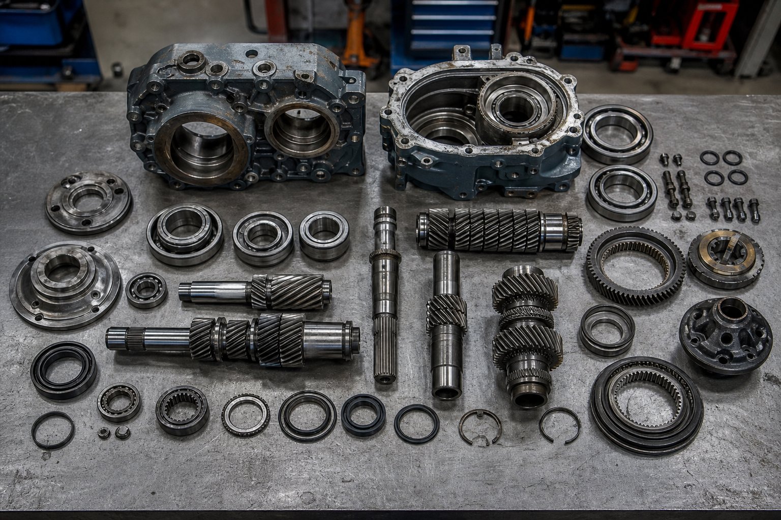
That question — repair or replace — rarely arrives at a convenient moment. It usually surfaces during a shutdown inspection when a technician opens the gearbox housing and finds damage that cannot be ignored, or when oil analysis reports show wear-metal trends climbing toward critical thresholds. The pressure to get the line running again competes directly with the need to make a financially sound, long-term decision. Rush the call, and you risk pouring repair dollars into a unit that fails again within months. Overcorrect toward replacement, and you may spend six figures on a new gearbox when a well-executed rebuild could have delivered years of additional service at a fraction of the cost.
What separates a good decision from an expensive mistake is a structured evaluation process — one that weighs the severity of damage, the availability of extruder gearbox parts, the remaining useful life of the housing and gear train, and the strategic direction of the extrusion line itself.
Signs That Your Extruder Gearbox Needs Attention
Gearbox degradation does not announce itself with a single, dramatic event. It escalates through a predictable sequence of warning signs, each one indicating a deeper level of internal damage and a higher urgency for action. Recognizing where your gearbox sits on this escalation ladder determines whether you have weeks to plan an intervention — or days before the problem makes the decision for you.
- Increasing vibration amplitude at gear-mesh frequencies. This is often the earliest measurable indicator. When monthly vibration data shows a rising trend at the calculated gear-mesh frequency (number of teeth multiplied by shaft RPM divided by 60) or growing sidebands around it, the gear tooth surfaces are changing — micropitting is progressing, backlash is increasing, or load distribution is shifting. At this stage, the gearbox is still fully operational, and you have the luxury of scheduling a closer investigation during a planned shutdown. Urgency: low to moderate.
- Rising oil temperature under the same load conditions. If your sump temperature has crept up by 5 to 10 degrees Celsius over several months without any change in production speed, ambient conditions, or cooling water supply, internal friction is increasing. This typically points to bearing degradation, oil quality decline, or a combination of both. Cross-reference with oil analysis results and vibration trends to narrow the root cause. Urgency: moderate.
- Metal particles appearing in oil analysis. Iron concentrations trending upward through the caution range (100 to 200 ppm) signal accelerating gear or bearing wear. Copper spikes indicate thrust washer or bearing cage degradation. Chrome particles point to hardened bearing race damage. When multiple wear metals rise simultaneously, the damage is no longer localized — it is propagating through the drivetrain. Urgency: moderate to high.
- Audible gear noise changes. A tonal shift — a new whine, growl, or intermittent clicking that was not present at baseline — means the damage has progressed to a point where tooth engagement geometry has changed perceptibly. Grinding sounds indicate metal-to-metal contact without adequate oil film. By the time a gearbox is audibly different, the window for preventive action has narrowed significantly. Urgency: high.
- Output shaft runout exceeding tolerance. When a dial indicator on the output shaft shows radial runout beyond the OEM specification (typically 0.02 to 0.05 mm for extruder service), bearing wear has progressed far enough to affect shaft positioning. In extrusion, this runout transmits directly to the screw, causing uneven barrel wear and degrading product quality. This finding usually emerges during an annual inspection or a coupling alignment check. Urgency: high.
- Visible oil leaks at seals. Fresh oil weeping or dripping from shaft seals, housing split lines, or sight glass gaskets is the most visible — and most commonly dismissed — warning sign. While a small leak may seem harmless, it means contaminants are entering the gearbox at the same point oil is leaving. Fine abrasive particles from the plant environment accelerate every internal wear mechanism. Persistent leaks that recur after seal replacement may indicate housing bore wear or shaft surface damage at the seal contact zone. Urgency: moderate (single occurrence) to high (recurring or multiple locations).
Any single sign on this list warrants investigation. Two or more occurring simultaneously demand a thorough internal inspection and a deliberate repair-or-replace evaluation — not a quick fix and a hope that the problem resolves itself.
When Repair Makes Sense vs. When to Replace
The repair-versus-replacement decision is not a gut call. It is a structured assessment of damage extent, component availability, cost economics, and strategic fit. The following framework compares the two options across the criteria that matter most to plant managers and maintenance teams evaluating an extruder gearbox replacement or rebuild.
| Decision Factor | Repair / Rebuild | Full Replacement |
|---|---|---|
| Typical Scenarios | Bearing fatigue or spalling; seal failure; isolated gear tooth pitting that has not progressed to spalling; thrust washer wear; minor shaft surface damage at seal zones | Extensive gear tooth spalling or breakage across multiple teeth; housing bore wear beyond re-machining limits; cracked housing; obsolete design with unavailable components; capacity upgrade required |
| Cost Range Relative to New | 20% to 50% of new gearbox cost, depending on scope of damage and parts required | 100% (new) or 60% to 80% (factory-remanufactured unit with warranty) |
| Turnaround Time | 1 to 4 weeks typical, depending on parts lead time and workshop capacity | 4 to 16 weeks for new OEM unit; 2 to 6 weeks for a stock or remanufactured replacement |
| Expected Life After Service | 5 to 10+ years if gear teeth, housing bores, and shaft journals are within tolerance and quality replacement parts are used | 15 to 20+ years with proper maintenance; full OEM design life |
| Risk Level | Low to moderate — provided root cause is addressed and all wear-related components are replaced, not just the failed part | Low — new unit carries full OEM warranty and validated design specifications |
| Best For | Gearboxes with localized damage where the housing and majority of the gear train remain serviceable; units still supported with available parts; situations where downtime must be minimized | Units with widespread internal damage; legacy gearboxes where parts are no longer available; lines being upgraded to higher throughput; situations where long-term reliability outweighs short-term cost |
Factors That Favor Repair
An extruder gearbox rebuild makes financial and operational sense when the damage is contained and the core structure of the unit remains sound. Specifically, repair is the stronger option when:
- Damage is limited to bearings, seals, or thrust washers — components designed to be replaced as wear items throughout the gearbox's service life
- Gear tooth surfaces show only early-stage micropitting or isolated pitting that has not progressed to destructive spalling — grinding or lapping the tooth surfaces may restore acceptable contact geometry
- Housing bore dimensions remain within tolerance, or can be restored to specification through line boring and the fitting of new bearing outer races
- The gearbox model is still actively supported by the OEM or has a well-established aftermarket supply chain for replacement gears, shafts, bearings, and seals
- The extruder line is not scheduled for a capacity upgrade — meaning the repaired gearbox's torque and speed ratings still match production requirements
One factor that frequently determines whether a repair is practical is the availability of quality replacement components. Gears must match the original tooth profile, material specification, and heat treatment. Shafts require precise dimensional conformance to housing bore and bearing fits. Thrust bearing assemblies must meet or exceed the original load rating. For current-production gearbox models, OEM parts are the default — though often expensive and subject to long lead times.
For older or OEM-discontinued models, sourcing becomes the critical bottleneck. This is where specialized spare-parts suppliers play an essential role. Companies like NANHAIYA manufacture extruder gearbox parts — including gears, shafts, thrust bearing assemblies, and seals — based on customer-supplied drawings, samples, or measured dimensions. That capability is particularly valuable when the original manufacturer no longer supports the gearbox model, when OEM lead times are unacceptable, or when the cost of factory-original components pushes the total repair bill beyond the point of economic justification.
Factors That Favor Replacement
Replacement becomes the better path when the damage extends beyond what repair can address reliably, or when the broader context of the extrusion operation has shifted. Consider replacement when:
- Multiple gear stages show extensive spalling, tooth breakage, or scuffing damage — rebuilding a gear train with this level of destruction often approaches or exceeds the cost of a new unit while delivering shorter expected life
- Housing bores have worn beyond the limits of re-machining — bore ovality or surface damage that cannot be corrected through line boring means the housing can no longer position bearings and shafts with the precision required for rated performance
- The gearbox design is obsolete, with no source — OEM or aftermarket — for critical components such as proprietary gear sets or specialized thrust assemblies
- The extrusion line is being upgraded to higher output capacity, requiring a gearbox with a higher torque rating, different gear ratio, or improved thrust-load handling that the existing unit cannot provide even in fully rebuilt condition
- Repeated failures within short intervals suggest a fundamental design limitation — undersized bearings, inadequate cooling capacity, or a torque rating too close to the actual operating load — that repair cannot correct
A useful rule of thumb from industrial gearbox maintenance practice: when the estimated repair cost exceeds 50 percent of the replacement cost, and the repaired unit's expected service life is less than half of a new gearbox's projected life, replacement is almost always the better financial decision. Industry experience also confirms that hidden costs — including repeated downtime for subsequent repairs, staff time invested in troubleshooting recurring issues, and the production quality risk of running a marginally repaired unit — can make an apparently cheaper repair more expensive than replacement over a two- to three-year horizon.
There is also a middle path that experienced plant engineers use but rarely discuss openly: the strategic spare. If your oil analysis and vibration trends indicate that a gearbox is degrading but still has months of remaining service life, use that time to source a replacement unit — whether new, remanufactured, or rebuilt from a trusted shop — and stage it on-site. When the swap finally happens, it takes hours instead of weeks, and the failed unit becomes the candidate for a no-pressure, thorough rebuild that can later serve as the spare for the next exchange. This rotating-spare strategy converts every gearbox replacement from an emergency into a planned event, and it is one of the most effective reliability practices available to multi-line extrusion plants.
Whether the decision lands on repair, replacement, or a staged spare strategy, the next challenge is the same: finding the right components and the right supplier to execute the plan on time and on spec. That sourcing process — and the criteria that separate a reliable parts supplier from a risky one — deserves its own focused discussion.
Emerging Trends in Extruder Gearbox Technology
Repair-or-replace decisions always carry an implicit forward-looking question: if you invest in a new gearbox today, will it still meet your production demands five or ten years from now? The answer depends on where extruder gearbox technology is heading — and it is heading toward higher torque density, lower energy consumption, smarter onboard diagnostics, and designs purpose-built for the increasingly demanding world of recycled-material processing. Engineers evaluating capital investments or major rebuilds should understand these trends, because the gearbox you specify today will shape your line's capability ceiling for the next decade or more.
High-Torque-Density and Energy-Efficient Designs
Torque density — measured in Nm/cm3 — is the metric that best captures how much usable power a gearbox can deliver relative to its physical size. And it has been climbing steadily. Modern twin-screw compounding gearboxes now achieve torque densities of 18 Nm/cm3, representing roughly a 30 percent increase over previous-generation designs. That jump is not the result of simply building bigger housings. It comes from a combination of improved gear geometry, higher-strength gear materials, and advanced surface treatments — carburizing for deep case hardness, nitriding for surface wear resistance, and shot peening to introduce beneficial compressive residual stresses that resist fatigue crack initiation at the tooth root.
What does this mean in practice? A high torque extruder gearbox with 18 Nm/cm3 density can deliver the same output torque as an older design in a significantly smaller footprint — or, conversely, deliver substantially more torque from the same frame size. For processors running glass-filled polyamide, glass-reinforced polypropylene, or other high-viscosity compounds that previously hit torque limits before reaching target throughput, this density improvement can enable up to a 100 percent increase in production rate without changing the extruder frame or barrel assembly. The gearbox, not the screw, was the bottleneck — and the new generation eliminates it.
Energy efficiency improvements run parallel to torque density gains. Every percentage point of efficiency lost in a gear stage becomes heat that the lubrication system must dissipate — and as discussed earlier, excess heat accelerates every wear mechanism and shortens oil life. A three-stage gearbox running at 97 percent efficiency per stage delivers only about 91 percent overall efficiency, meaning 9 percent of the motor's electrical power converts to waste heat. An energy efficient extruder gearbox design attacks that loss from multiple angles:
- Optimized gear-tooth profiles — modern CNC grinding and profile modification techniques produce tooth geometries that minimize sliding friction at the mesh while maintaining load capacity. Micro-geometry corrections (tip relief, lead crowning) ensure smooth load transfer and reduce dynamic mesh forces.
- Low-friction bearing designs — hybrid ceramic rolling elements, optimized internal clearances, and advanced cage materials reduce rolling resistance and heat generation at each bearing position.
- Improved sealing systems — low-drag lip seals and non-contact labyrinth seals reduce the parasitic friction that conventional contact seals impose, especially at higher shaft speeds. The energy savings are modest per seal, but they compound across multiple seal positions.
Taken together, these refinements can push overall gearbox efficiency above 97 percent in two-stage designs — reducing both electrical consumption and the cooling capacity required to keep oil temperatures in the safe operating range.
Gearboxes Engineered for Recycled-Material Processing
The global push toward circular plastics is reshaping what extruder gearbox technology must deliver. Processing recycled and post-consumer resin is fundamentally harder on the drivetrain than running virgin material — and gearbox designs are evolving to meet that challenge.
Why is recycling harder on the gearbox? Three factors converge. First, recycled feedstocks have highly variable melt viscosity. A bale of post-consumer HDPE may contain material from dozens of sources with different melt flow indices, filler loadings, and contamination levels. That variability translates to fluctuating torque demand at the screw — the gearbox sees constant load swings rather than the steady-state conditions that virgin processing provides. Second, contaminated feedstocks containing paper labels, adhesive residues, metal fragments, and mixed polymers require higher screw pressures and more aggressive screw designs to achieve adequate melt quality. Those higher pressures increase thrust loads on the gearbox, often by 20 to 40 percent compared to the same extruder running virgin resin. Third, aggressive processing conditions — higher barrel temperatures, more intensive mixing elements, extended residence times for devolatilization — push the entire drivetrain closer to its thermal and mechanical limits.
Gearbox manufacturers are responding with designs that address each of these stresses directly. Reinforced thrust bearing assemblies with higher dynamic load ratings accommodate the elevated and fluctuating axial forces. Enhanced filtration on lubrication circuits — finer mesh elements, magnetic debris traps, and more frequent bypass filtration cycles — protects gear and bearing surfaces from the accelerated contamination that recycling operations generate. Overload-tolerant gear designs with conservative service factors provide the headroom for torque spikes that occur when inconsistent feedstock hits the screw.
The broader picture is one of convergence: the demands of recycling are pushing gearbox development in the same direction as the pursuit of higher performance — toward stronger materials, smarter monitoring, and more robust thermal management. Here is a summary of the key innovation trends shaping the next generation of extruder gearbox technology:
- High-torque-density gear trains — delivering 18+ Nm/cm3 through optimized gear geometry and a Do/Di ratio around 1.55 for twin-screw applications
- Advanced gear materials and coatings — carburized and nitrided alloy steels, superfinished tooth flanks, and DLC (diamond-like carbon) coatings for extreme wear resistance
- Energy-efficient architectures — precision-ground tooth profiles, hybrid ceramic bearings, and low-drag seals that push overall efficiency above 97 percent
- Smart gearboxes with integrated IoT sensors — onboard vibration, temperature, and oil debris monitoring that feeds directly into plant-wide condition monitoring platforms, enabling truly predictive maintenance without manual data collection
- Designs optimized for recycled-material extrusion — reinforced thrust assemblies, enhanced oil filtration, and overload-tolerant gear ratings to handle the variable and aggressive conditions that post-consumer resin processing demands
For plant engineers, the practical takeaway is this: when specifying a replacement gearbox, evaluate whether the new unit incorporates any of these advances. A gearbox purchased today with 18 Nm/cm3 torque density, integrated sensor provisions, and a thrust bearing assembly rated for recycling-grade loads positions your line for the next ten to fifteen years of evolving material and regulatory demands — not just today's production schedule.
Of course, whether you are investing in next-generation hardware or keeping a legacy unit running through a well-executed rebuild, the execution depends on one common factor: sourcing the right components from the right supplier. And that process has its own set of evaluation criteria worth understanding before the next purchase order goes out.
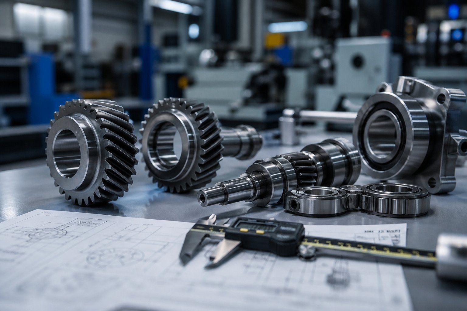
Sourcing Extruder Gearbox Parts and Components
A perfectly sound repair-or-replace decision falls apart the moment you cannot find the right parts at the right quality within an acceptable lead time. It happens more often than most plant managers care to admit. The gearbox is disassembled on the shop floor, the damaged bearing or worn gear set has been identified, and the rebuild plan is ready — but the supplier quote comes back with a 14-week lead time, or the OEM informs you the model has been discontinued and parts are no longer stocked. Suddenly, a planned repair turns into an emergency scramble, and procurement pressure replaces engineering judgment.
Avoiding that scenario starts well before the gearbox ever comes apart. It starts with knowing what to look for in a supplier, understanding the three main sourcing paths available, and building relationships with vendors who can deliver extruder gearbox spare parts on your timeline — not theirs.
What to Look for in a Gearbox Parts Supplier
Not every machine shop or industrial parts distributor is equipped to produce the precision components that an extruder gearbox demands. Helical gears require specific tooth profile accuracy (DIN or AGMA quality grades), controlled case hardening depths, and surface finishes that directly affect noise, load distribution, and fatigue life. Shafts must hold bearing-journal tolerances within microns. Thrust bearing assemblies must meet or exceed the original dynamic load rating under continuous axial force.
When you are evaluating potential suppliers for extruder replacement parts, these criteria separate the capable from the risky:
- Ability to manufacture from drawings, samples, or reverse-engineered dimensions — Many legacy gearboxes predate digital design files. Your supplier needs the metrology capability to measure a worn part, compensate for the wear, and produce a replacement to the original specification. Reverse engineering legacy parts through 3D scanning and CAD reconstruction has become a practical solution for components where no drawings exist, but the supplier must have experience interpreting scan data for functional gearbox parts — not just cosmetic replicas.
- Material certifications and heat-treatment capabilities — Gears and shafts are only as good as their metallurgy. Insist on material test certificates (EN 10204 Type 3.1 or equivalent) that verify alloy composition, and confirm that the supplier controls or directly supervises heat treatment processes — carburizing, nitriding, through-hardening, and tempering. A gear cut from the right profile but heat-treated incorrectly will fail faster than the part it replaced.
- Quality control processes — Look for dimensional inspection capabilities (CMM measurement), hardness testing (Rockwell, Vickers, or case-depth verification), and gear-tooth profile verification using dedicated gear inspection equipment. A supplier who can provide an inspection report showing lead, profile, pitch, and runout deviations against the design specification gives you confidence before the part ever reaches your plant.
- Cross-brand compatibility experience — Plants running gearboxes from multiple OEMs need a supplier who understands the design conventions of different manufacturers and can produce components that fit housings from Flender, Radicon, Eisenbeiss, or any other brand without requiring the original manufacturer's involvement.
- Lead time and logistics reliability — A part that arrives two weeks late costs far more than its purchase price when an extrusion line sits idle. Supplier evaluation best practices emphasize that delivery consistency is as important as product quality — ask for on-time delivery metrics and references from comparable customers before committing to a critical order.
- Technical support for part identification — When you hand a supplier a worn gear and a photograph of the nameplate, can their engineering team identify the module, pressure angle, helix angle, face width, number of teeth, and material grade? That technical competence — not just machining capacity — determines whether you get a functional replacement or an expensive paperweight.
One practical test: before placing a critical production order, send the supplier a smaller, non-urgent component first. Evaluate the dimensional accuracy, surface finish, documentation quality, and communication responsiveness on that trial order. You will learn more from one real transaction than from ten capability presentations.
Sourcing Strategies for OEM and Non-OEM Components
Three distinct sourcing paths exist for extruder gearbox spare parts, and each serves a different situation. The smartest procurement teams do not default to one path for every purchase — they match the sourcing strategy to the specific part, the gearbox's age and criticality, and the urgency of the need.
Path 1: OEM direct. Purchasing replacement parts directly from the original gearbox manufacturer guarantees dimensional compatibility and material specification conformance. For gearboxes still under warranty or within their first decade of service, OEM parts are often the safest choice — especially for proprietary components like custom distribution gears in twin-screw units. The trade-off is cost and lead time. OEM parts typically carry a 30 to 40 percent premium over equivalent aftermarket alternatives, and delivery timelines through dealer or factory channels can stretch to 8 to 16 weeks for non-stock items. For plants that can plan ahead and absorb the cost, OEM sourcing minimizes technical risk.
Path 2: Authorized aftermarket. Several reputable aftermarket manufacturers produce gears, bearings, seals, and shaft components that meet OEM specifications without the OEM price tag. These suppliers often serve multiple gearbox brands and maintain inventories of common wear parts — giving them a lead-time advantage over factory-direct channels. Quality from established aftermarket suppliers is generally reliable, though it varies more widely than OEM supply. The key is verification: request material certificates, dimensional inspection reports, and hardness test results with every order. Aftermarket sourcing works well for standard bearings, seals, and common gear sizes where the specifications are well-documented and the supplier has a track record in extrusion applications.
Path 3: Specialized custom manufacturers. This is the path that becomes essential when the other two are no longer viable — and for a surprising number of extrusion plants, that situation is more common than the industry acknowledges. Gearboxes that have been running for 15, 20, or 25 years may come from manufacturers who have been acquired, merged, or closed. The original part numbers may no longer exist in any catalog. Drawings may never have been shared with the end user. In these cases, a specialist supplier who can produce extruder replacement parts based on physical samples, customer-supplied drawings, photographs, or measured dimensions is not a convenience — it is the only option.
Companies like NANHAIYA operate in exactly this space, manufacturing gearbox-related components — gears, shafts, thrust bearing assemblies, and seals — alongside other critical extruder spare parts such as screw tips, check rings, die heads, and pelletizing blades, all produced to customer specifications. For maintenance teams managing used extruders or legacy equipment where OEM support has ended, this custom-manufacturing capability can mean the difference between a cost-effective rebuild and a forced full replacement at several times the cost.
For many extrusion plants running legacy equipment, custom-manufactured replacement parts are the only viable option when OEM support has ended — and the ability to produce precision components from a sample or a set of measurements is what keeps those lines running.
The right sourcing strategy often combines all three paths across different component categories. You might source a proprietary distribution gear from the OEM, standard rolling bearings from an authorized aftermarket distributor, and a custom-machined output shaft from a specialist manufacturer — all for the same rebuild project. That blended approach optimizes cost, lead time, and quality risk simultaneously.
Whatever path you choose, document everything. Record the supplier, part number, material certification, inspection results, and installation date for every component that goes into a gearbox rebuild. That documentation is not bureaucratic overhead — it is the data foundation that allows your condition monitoring program to correlate part quality with service life, identify which suppliers deliver components that last, and make smarter sourcing decisions on the next rebuild. Over time, that feedback loop becomes one of the most valuable assets your maintenance organization owns.
Frequently Asked Questions About Extruder Gearboxes
1. What does an extruder gearbox do?
An extruder gearbox is a speed-reduction and torque-multiplication unit that sits between the drive motor and the extruder screw. It converts the motor's high-speed, low-torque output into the low-speed, high-torque rotation needed to push polymer melt through the barrel and die. Unlike standard industrial reducers, it simultaneously handles torsional loads from melt resistance, radial loads from helical gear mesh forces, and continuous axial thrust loads generated by screw pressure — which can exceed 500 kilonewtons in large extruders. The integrated thrust bearing assembly absorbs this axial force so it never reaches the motor bearings, making the gearbox uniquely engineered for extrusion duty.
2. How do I know if my extruder gearbox is failing?
Extruder gearbox failure follows a predictable escalation of warning signs. The earliest indicators are rising vibration amplitude at gear-mesh frequencies and gradual increases in oil sump temperature under the same load conditions. Next, oil analysis may reveal increasing concentrations of iron, copper, or chromium wear metals. Audible changes such as new whining, grinding, or clicking sounds indicate more advanced damage. Output shaft runout exceeding OEM tolerances (typically 0.02 to 0.05 mm) and persistent oil leaks at shaft seals are also strong indicators. Critically, gearbox degradation often manifests first as unexplained product quality issues — wall-thickness variation, gauge bands in film, or surface defects — that are frequently misdiagnosed as screw, barrel, or material problems.
3. What type of oil should I use in an extruder gearbox?
The three main lubricant types for extruder gearboxes are mineral-based EP (extreme-pressure) gear oils, synthetic PAO (polyalphaolefin) oils, and polyglycol (PAG) lubricants. Mineral EP oils in ISO VG 220 or 320 grades suit standard-duty applications with change intervals of 4,000 to 6,000 operating hours. Synthetic PAO oils offer superior thermal stability, lower friction, and extended intervals of 10,000 to 15,000 hours — often reducing sump temperatures by 5 to 15 degrees Celsius compared to mineral oils. PAG lubricants are specified by certain OEMs for worm gear units but cannot be mixed with mineral or PAO products. Always verify the correct viscosity grade and base oil type against your gearbox manufacturer's data sheet before filling.
4. Should I repair or replace a damaged extruder gearbox?
The decision depends on damage extent, parts availability, and cost economics. Repair typically makes sense when damage is limited to bearings, seals, or early-stage gear pitting, and the housing bores remain within tolerance — costing roughly 20 to 50 percent of a new unit. Replacement is the better path when multiple gear stages show extensive spalling or tooth breakage, housing bores are worn beyond re-machining limits, or the model is obsolete with no available components. A practical rule of thumb: if repair cost exceeds 50 percent of replacement cost and the rebuilt unit's expected life is less than half that of a new gearbox, replacement usually wins financially. For older or discontinued models, specialist suppliers like NANHAIYA can manufacture gears, shafts, and thrust assemblies from drawings or samples, often making repair viable where OEM parts are no longer available.
5. What is the difference between single-screw and twin-screw extruder gearboxes?
Single-screw extruder gearboxes drive one output shaft using a straightforward parallel-shaft gear train with two or three reduction stages. Their primary engineering challenge is absorbing high axial thrust loads, with generous space for a large thrust bearing assembly. Twin-screw gearboxes are far more complex — they must synchronize two parallel output shafts at precisely the same speed with exact angular timing, using a torque-distribution gear stage. The narrow center distance between intermeshing screws constrains bearing size and concentrates heavy loads into compact spaces. Single-screw units serve pipe, film, profile, and sheet extrusion, while twin-screw gearboxes handle compounding, reactive extrusion, devolatilization, and recycling. Twin-screw gearboxes carry a significant cost premium and demand more specialized maintenance and overhaul procedures.
Written by
Nanhaiya Technical Team
Zhoushan Nanhaiya Plastic Machinery Co., Ltd.
The Nanhaiya technical team supports screw and barrel manufacturing projects through application review, technical communication, custom manufacturing coordination, and production and quality control.
Discuss Your Application
Related Articles
More insights on screw barrel technology and plastics processing.

What Nobody Tells You About Screw Barrel For Plastic Machine Design
Oct 10, 2026
Learn how screw barrel for plastic machine design affects melt quality, throughput, and wear life. Covers geometry, resin matching, troubleshooting, and sourcing.
Read Article
Single Screw Extruder for Sheet: Stop Guessing, Start Specifying
Oct 9, 2026
Learn how to specify a single screw extruder for sheet production. Covers screw geometry, resin-specific processing, troubleshooting, and maintenance best practices.
Read Article
PE Pipe Extruder Machine: What Datasheets Won't Tell You
Oct 9, 2026
Learn how a PE pipe extruder machine works, key specs explained, material grade selection, maintenance tips, and buyer guidance beyond the datasheet.
Read ArticleLooking for something else?
Search by material, symptom or product and jump straight to the relevant page.
These are navigation suggestions based on keyword matching — not a quotation, not a delivery commitment, and not a substitute for engineering review. Final specification is confirmed by our engineers against your drawings and processed material.
Need help with screw barrel selection?
Share your machine model, processed material and application. Our team can help with pricing and technical support.