

What Extruder Barrels Are and Why They Matter
Imagine running a high-output extrusion line and watching part quality slowly drift — thicker walls here, thinner spots there, surface defects that weren't showing up six months ago. You bump up heater setpoints, tweak screw speed, and adjust backpressure. Nothing sticks. The root cause? A worn extruder barrel quietly undermining every kilogram of polymer you process.
Most processors think about the screw first. That's understandable — it's the visible, moving component. But the barrel is the other half of the equation, and when it degrades, no amount of process tuning can compensate.
What Is an Extruder Barrel
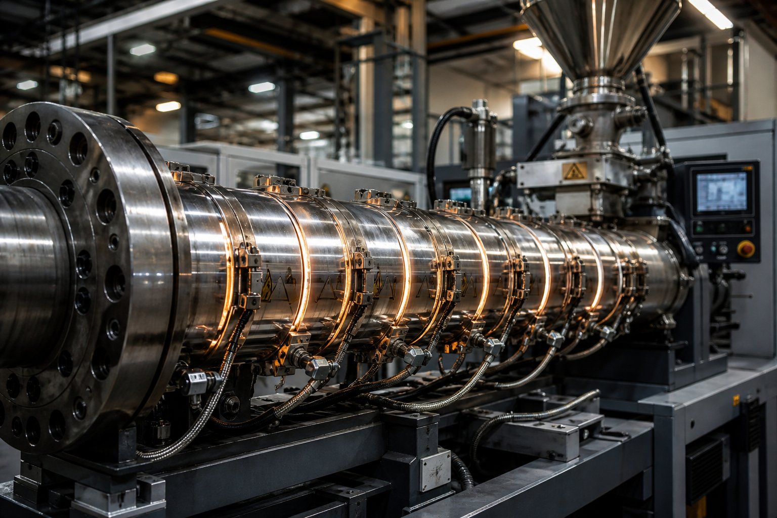
An extruder barrel is the cylindrical steel housing that contains the rotating screw, creates the pressure and temperature environment for melting and conveying polymer, and defines the processing zone geometry. In both plastic extrusion and injection molding systems, it serves as the primary containment structure where raw pellets transform into a homogeneous, pressurized melt ready for shaping.
The barrel's inner bore provides the tight clearance against which the screw generates shear, compression, and forward conveyance. Heating elements mounted along its outer surface deliver thermal energy zone by zone, while thermocouples embedded in the barrel wall feed temperature data back to the controller. In some designs, cooling channels or air blowers manage heat removal in critical zones like the feed throat.
Here's the key point many specifications overlook: the barrel and screw operate as an interdependent system, not as isolated components. The screw's flight geometry is designed around a specific bore diameter, and even small increases in that diameter due to wear change the shear environment, reduce compression efficiency, and allow melt to leak backward past the flights. You'll notice that a worn barrel doesn't just affect itself — it degrades the screw's ability to do its job, too.
Why Barrel Performance Matters
A barrel in good condition does far more than simply contain molten plastic. It actively shapes melt quality through precise thermal control, mechanical containment, and pressure management. When barrel performance declines, the downstream effects ripple through the entire process:
- Melt homogeneity drops — uneven bore clearance creates inconsistent shear, leading to temperature gradients and viscosity variation within the melt stream.
- Dimensional consistency suffers — extrudate thickness, weight, and geometry become harder to hold within tolerance as pressure stability erodes.
- Energy consumption rises — a degraded barrel forces operators to increase screw speed, backpressure, or heater output to compensate for lost processing efficiency.
- Maintenance costs escalate — reactive repairs, unplanned shutdowns, and premature screw replacement all trace back to barrel condition that went unmonitored for too long.
The barrel is not a passive container — it is an active thermal and mechanical element that shapes every kilogram of polymer processed through the line.
This article covers the complete extruder barrel lifecycle — from selecting the right type and liner material, through thermal management and wear detection, all the way to reconditioning and replacement decisions. Whether you're specifying a new barrel for a greenfield line or evaluating whether your current one has another year of service left, the goal is the same: make smarter barrel decisions backed by engineering fundamentals, not guesswork.
Types of Extruder Barrels From Single-Screw to Twin-Screw Designs
Not all extruder barrels are built the same way — and they shouldn't be. The barrel you need depends on the polymer you're processing, the throughput you're targeting, and the level of mixing or degassing your application demands. Yet barrel types are often lumped together in vague categories, leaving processors to guess which configuration actually fits their line. Here's a clearer breakdown.
Single-Screw Extruder Barrels
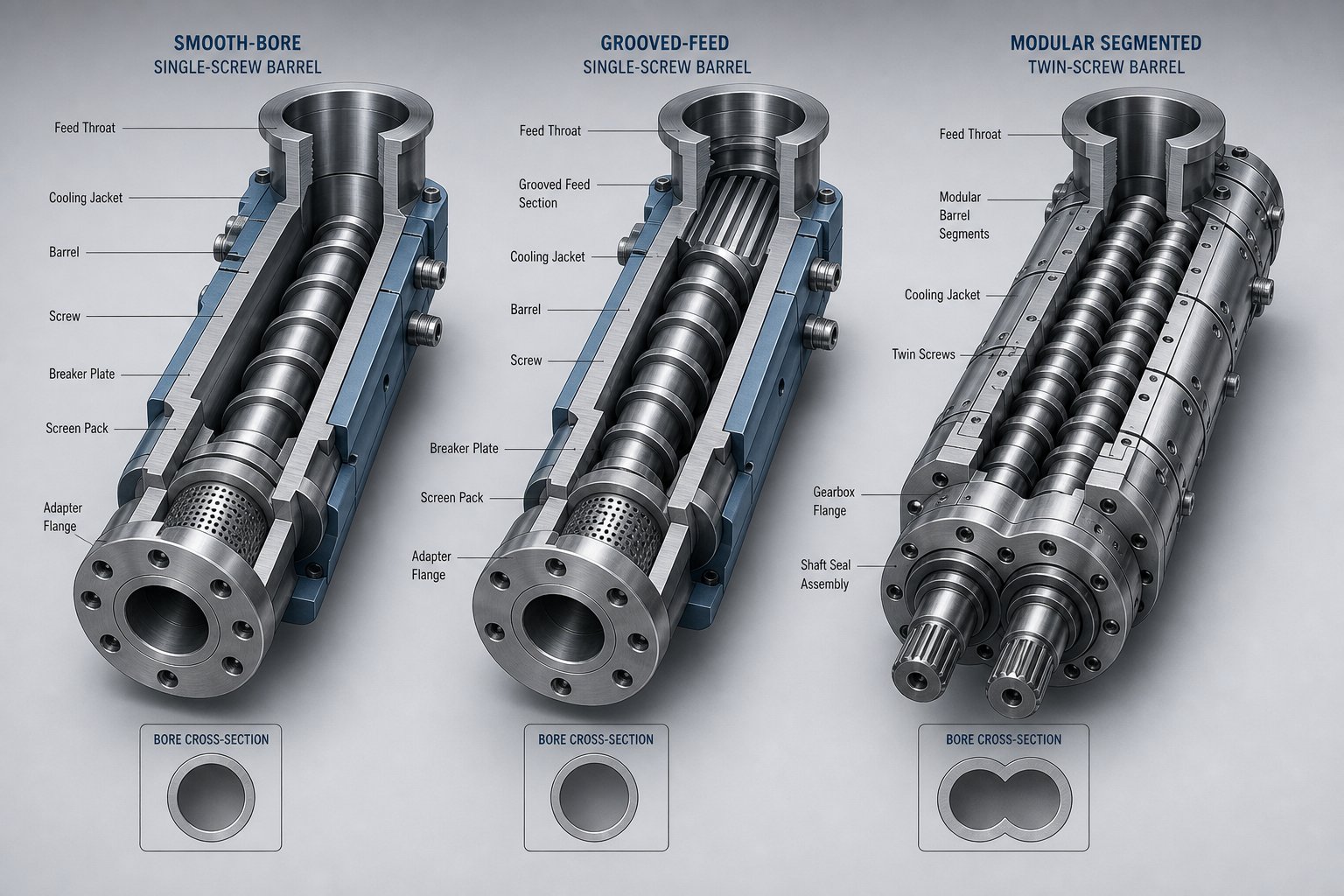
Single-screw systems remain the workhorses of plastic extrusion, and they come in two fundamentally different feed section designs: smooth bore and grooved feed. The distinction matters more than most specs suggest.
A smooth-bore barrel features a polished, uniform inner surface from the feed throat through the entire length. Solids conveying in this design depends on the frictional difference between the polymer pellets and two surfaces — the barrel wall and the screw root. The barrel needs to grip the pellets better than the screw does, pushing material forward. Smooth-bore designs work well for a wide range of commodity and engineering polymers, and they're simpler to manufacture and maintain.
A grooved-feed barrel, by contrast, features longitudinal or helical grooves machined into the feed zone's inner wall. These grooves mechanically lock solid pellets against the barrel surface, dramatically increasing frictional forces in the feed section. The result? Solids move forward faster and more consistently, independent of the friction coefficient of the polymer itself. Case studies comparing grooved and smooth-bore extruders processing high-viscosity HDPE have shown that grooved-feed designs achieve equivalent throughput at lower melt temperatures and reduced energy consumption — in some cases cutting power draw enough to save tens of thousands of dollars per year.
There's a tradeoff, though. The higher mechanical stress created by positive solids conveying in the grooved section generates significantly more pressure and wear. Grooved extruder feed barrel designs require harder liner materials — often bimetallic or tool steel liners — and more robust cooling in the feed throat to prevent premature melting that would defeat the groove's purpose. If you're running unfilled polyolefins at high rates, a grooved-feed barrel can be transformative. For lower-output applications with less demanding resins, a smooth bore may deliver all the performance you need at lower capital and maintenance cost.
Twin-Screw Extruder Barrels
Twin screw barrel construction looks nothing like its single-screw counterpart. Instead of a single continuous cylinder, most twin-screw systems — especially co-rotating intermeshing designs — use a segmented, modular barrel architecture. Individual barrel segments bolt together in sequence, and each segment can be configured differently depending on its role in the process.
Imagine building a processing line like assembling blocks. One segment might have a closed bore for high-pressure conveying. The next might feature an open top port for a side stuffer that introduces glass fibers or mineral fillers downstream. Another segment could include a vent port — either atmospheric or connected to vacuum — for removing moisture or volatiles. This modularity gives twinscrew compounders extraordinary flexibility to reconfigure the barrel layout when formulations change or when process optimization demands a different zone arrangement.
Co-rotating twin-screw extruders excel at dispersive and distributive mixing, making them the default choice for compounding, reactive extrusion, and multi-component blending. Counter-rotating designs generate stronger conveying forces with lower shear between flights — better suited for shear-sensitive materials like PVC or certain thermoplastic elastomers. In both cases, the barrel's figure-eight bore profile and segmented construction create a fundamentally different wear and thermal management challenge compared to single-screw systems.
Vented and Degassing Barrel Configurations
When you're processing hygroscopic polymers like nylon or PET, or working with materials that release volatile byproducts during melting, trapped moisture and gases can wreak havoc on part quality. Bubbles, splay marks, and reduced mechanical properties are all symptoms of inadequate degassing. Vented barrel configurations solve this by providing controlled escape routes for volatiles during processing.
Atmospheric vent ports are the simplest approach — an opening in the barrel wall at a decompression zone where the screw geometry deliberately reduces pressure, allowing entrapped air and light volatiles to escape. Vacuum vent ports take this further by applying negative pressure — typically via a liquid ring vacuum pump — to extract moisture, monomer residues, and volatile organic compounds more aggressively. Many extrusion lines use both: an atmospheric vent upstream to remove bulk air, followed by a vacuum vent downstream for deep devolatilization.
Vented barrels require careful screw design to maintain a melt seal that prevents polymer from flowing out of the vent opening. Get the screw geometry wrong, and you'll deal with vent flow — molten polymer pushing up through the port — which creates a mess and interrupts production. This reinforces the barrel-and-screw interdependence discussed earlier: barrel configuration drives screw design, and vice versa.
Barrel Type Comparison at a Glance
| Barrel Type | Construction | Typical Applications | Throughput Impact | Key Considerations |
|---|---|---|---|---|
| Single-Screw Smooth Bore | Continuous one-piece cylinder with polished inner bore | Commodity polymers, film, sheet, profile extrusion | Standard — output is friction-dependent | Simplest design; lower capital cost; suitable for most unfilled resins |
| Single-Screw Grooved Feed | Grooved feed zone (longitudinal or helical grooves) with smooth downstream bore | High-viscosity HDPE, pipe extrusion, high-output blown film | Higher — positive solids conveying decouples output from friction | Requires harder liner materials and aggressive feed throat cooling; higher feed zone wear |
| Twin-Screw Segmented | Modular bolt-together barrel segments with figure-eight bore | Compounding, reactive extrusion, filled and reinforced materials | High — configurable mixing and conveying zones | Individual segments can be replaced independently; ports enable feeding, venting, and side stuffing |
| Vented / Degassing | Barrel with atmospheric or vacuum vent ports at decompression zones | Hygroscopic polymers (nylon, PET), materials with volatile content | Maintains quality at target rates by removing volatiles | Requires matched screw design to maintain melt seal; vacuum systems add infrastructure |
Each of these barrel configurations creates a different internal environment — different pressure profiles, wear patterns, and thermal demands. That internal environment, in turn, determines which liner material can stand up to the job and which one will fail prematurely.
Barrel Liner Materials and How to Choose the Right One
Your barrel type sets the stage. But the liner material is what determines how long that barrel actually survives in service — and what polymers it can handle without premature failure. An extruder screw barrel processing unfilled polypropylene faces a completely different wear environment than one running 30% glass-filled nylon, and the liner must reflect that reality.
Choosing the wrong liner doesn't just shorten barrel life. It changes the economics of your entire extrusion barrel operation — more frequent replacements, more unplanned downtime, more scrap, and higher cost per kilogram of output. Here's how the major liner families compare, what each one handles well, and where each one falls short.
Nitrided Steel Barrels
Nitriding is the baseline — the most common and most affordable barrel surface treatment in the industry. The process works by diffusing nitrogen into the bore surface of a nitriding-grade alloy steel (typically 38CrMoAlA or its equivalents like Nitralloy 135M) at temperatures between 500 and 550 degrees Celsius. This creates a hardened case with surface hardness in the range of 950 to 1,100 HV — roughly 65 to 70 HRC equivalent. Beneath that case, the core retains the toughness and ductility of the base steel at approximately 280 to 320 HB.
Sounds impressive on paper. And for the right applications, it genuinely is. A nitrided screw barrel processing clean, unfilled polyolefins or general-purpose polystyrene can deliver five or more years of reliable service. The surface is hard enough to resist adhesive wear and mild abrasion, the bore maintains dimensional stability, and the cost is substantially lower than any alternative.
The critical limitation is case depth. A standard gas nitriding process produces a hardened layer only about 0.4 to 0.6 mm deep. Once abrasive wear penetrates through that thin case, the soft core beneath is exposed — and wear accelerates rapidly from that point. There's no second chance. For processors running filled compounds, recycled streams with contaminants, or corrosive resins like PVC, a nitrided barrel is often consumed in 12 to 18 months. That's when the math starts favoring a different approach entirely.
Bimetallic and Centrifugal Cast Liners
A bimetallic barrel separates two jobs that a nitrided barrel tries to combine into one material. The outer shell — still made from high-strength alloy steel — provides structural rigidity, supports heater bands, and carries mechanical loads. Inside the bore, a centrifugally cast wear-resistant alloy liner handles the actual contact with polymer and filler.
During manufacturing, the barrel shell rotates at controlled speed while molten alloy is introduced at approximately 1,100 degrees Celsius. Centrifugal force distributes the alloy evenly across the bore surface, and the result is a metallurgical bond between shell and liner. The finished liner thickness ranges from about 1.5 mm to 3.0 mm — giving it roughly five to six times the effective wear depth of a nitrided case. That difference is the fundamental reason bimetallic barrels last two to three times longer in moderate-wear applications, and up to seven times longer under severe abrasion.
The real specification decision lies in choosing the alloy family. Three primary options address different wear vectors:
- Iron-based alloys (Fe-Cr-B class) — These are the workhorse liners for general abrasive duty. Chromium and boron carbides dispersed in an iron matrix deliver hardness in the 58 to 62 HRC range. They're the economical default for processing compounds with moderate filler content — calcium carbonate, talc, or mid-level fiber loading. If you're stepping up from nitrided but don't face extreme conditions, iron-based liners are typically the right starting point.
- Nickel-based alloys (Ni-Cr-B-W class) — When the threat shifts from pure abrasion to corrosion — or a combination of both — nickel-based liners earn their premium. The nickel matrix resists chemical attack from acidic byproducts generated during PVC, CPVC, and halogenated flame-retardant processing. Hardness ranges from 60 to 65 HRC, and these alloys maintain their integrity at elevated temperatures, making them suitable for high-performance resins in the PEEK and PPS class.
- Tungsten-carbide-bearing alloys — For severe abrasion — think 30% or higher glass fiber loadings, heavy mineral fills, or abrasive recycled streams — tungsten carbide particles dispersed in a nickel or cobalt matrix deliver the highest effective wear resistance available in a centrifugally cast liner. Hardness reaches 65 to 70 HRC, and the carbide particles act as armor against the continuous grinding action of glass fibers against the bore surface.
A practical guideline from field service data: most neutral, moderately filled applications are well served by the iron-based family. Nickel earns its cost premium when chemistry or temperature attacks iron. Carbide earns its premium when filler is grinding everything else away.
Tool Steel and Specialty Liners
Some applications push beyond what even standard bimetallic liners can handle. This is where CPM (Crucible Particle Metallurgy) tool steels and specialty alloys enter the picture.
CPM tool steels — such as CPM 9V or CPM 10V — are produced through a powder metallurgy process that creates a fine, uniform carbide distribution impossible to achieve through conventional steelmaking. The result is a liner material that combines very high abrasion resistance with toughness that prevents chipping and spalling under mechanical shock. These steels are particularly relevant for processing highly abrasive glass-filled engineering plastics like 33% GF PA66, where the continuous glass fiber abrasion demands a liner that won't crack under the combined stress of high wear and high injection or conveying pressure.
For fluoropolymer processing — materials like PVDF, FEP, and PTFE that release hydrofluoric acid at elevated temperatures — specialty high-chromium, high-molybdenum alloys provide the corrosion resistance that standard nickel-based liners may not sustain over extended campaigns. These liners represent the highest cost tier but are essential where both the barrel bore and the extruder screw barrel surfaces face aggressive chemical attack during every processing hour.
HVOF (High-Velocity Oxy-Fuel) tungsten carbide coatings represent another specialty option. Achieving hardness levels of 70 to 75 HRC, these coatings are applied as a thin, extremely hard layer and are specified for the most extreme abrasion environments — silicon carbide-filled compounds or very high glass fiber percentages where even standard WC-bearing bimetallic liners wear faster than acceptable.
Liner Material Comparison
| Liner Material | Hardness Range | Abrasion Resistance | Corrosion Resistance | Typical Polymer Applications | Relative Cost Tier |
|---|---|---|---|---|---|
| Nitrided Steel (38CrMoAlA / Nitralloy 135M) | 950–1,100 HV (65–70 HRC equivalent) | Moderate — effective against adhesive and mild abrasive wear | Moderate — limited protection against acidic or halogenated byproducts | Unfilled polyolefins (PE, PP), polystyrene, general-purpose PET | Low (1.0x baseline) |
| Bimetallic — Iron-Based (Fe-Cr-B) | 58–62 HRC | High — chromium and boron carbides resist filler abrasion | Moderate — not recommended for corrosive chemistries | CaCO3-filled compounds, talc-filled PP, moderately filled engineering plastics | Medium (1.8–2.2x) |
| Bimetallic — Nickel-Based (Ni-Cr-B-W) | 60–65 HRC | High | High — nickel matrix resists HCl, HF, and acidic degradation products | PVC, CPVC, halogenated FR compounds, PEEK, PPS | Medium-High (2.2–2.8x) |
| Bimetallic — Tungsten Carbide-Bearing | 65–70 HRC | Very High — WC particles provide extreme abrasion resistance | Moderate to High (matrix-dependent) | Glass fiber-reinforced PA/PBT (30%+), high mineral loading, WPC | High (2.5–3.0x) |
| CPM Tool Steel (e.g., CPM 9V, 10V) | 58–62 HRC (varies by grade) | Very High — uniform fine carbide distribution | Moderate | Highly abrasive glass-filled engineering plastics, injection molding barrels for GF compounds | High (2.5–3.5x) |
| HVOF Tungsten Carbide Coating | 70–75 HRC | Extreme | Moderate | SiC-filled compounds, very high GF percentages, extreme abrasion environments | Very High (3.0x+) |
One pattern emerges clearly from this comparison: hardness alone doesn't tell you which liner to choose. A nitrided barrel's surface is technically harder than many bimetallic alloys on a Vickers scale — yet it fails far sooner in demanding applications because the hardened case is only a fraction of a millimeter deep. Effective wear life depends on the combination of hardness, wear depth, and resistance to the specific wear mechanism your process generates.
That brings up a critical question most liner comparisons skip over: how long should your extrusion barrel actually last, and what's eating it away? The answer depends on understanding not just what the liner is made of, but what's happening at the bore surface during processing — the specific wear mechanisms that quietly open up the gap between your screw flights and barrel wall.
Understanding L/D Ratio and Its Impact on Processing
Liner material determines how long a barrel survives. But barrel length — specifically the length-to-diameter ratio — determines how well it performs every minute it's in service. Get the L/D wrong, and even a perfectly lined barrel will produce subpar melt, waste energy, or degrade the very polymer it's supposed to process.
How L/D Ratio Shapes Melt Quality and Throughput
The L/D ratio is the single most referenced specification when sizing an extruder barrel. It's calculated by dividing the effective working length of the extruder screw by its outer diameter. A barrel with a 1,500 mm effective length and a 50 mm bore diameter has an L/D of 30:1.
Why does this number matter so much? Because L/D directly controls how long the polymer stays inside the barrel at any given screw speed — its residence time. That residence time governs heat absorption, viscosity development, mixing intensity, and devolatilization. A 24:1 barrel and a 36:1 barrel running the same extrusion screw at the same RPM will produce dramatically different melt quality from the same resin.
Longer L/D ratios — in the range of 30:1 to 36:1 for single-screw systems — provide more processing length for gradual melting, thorough mixing, and melt homogenization. The polymer has more time and more screw flight contact to reach a uniform temperature and viscosity before it hits the die. For high-output lines, this extra length also delivers greater stability at elevated screw speeds — reducing surging and die-face variation that shorter barrels struggle with at high RPM.
Shorter ratios — 20:1 to 24:1 — cut that residence time significantly. Less time in the barrel means less heat exposure, which is exactly what you want for thermally sensitive materials. But it also means less melting capacity, less room for mixing elements, and less margin for process variation. You're trading safety window for thermal protection.
Matching L/D Ratio to Polymer Requirements
Different polymers demand different processing envelopes, and L/D is where those demands translate into hardware specifications. Here's the practical breakdown:
- Semi-crystalline polymers with high melting points — resins like PET (melting around 260 degrees Celsius) and PA66 (around 260 degrees Celsius) need sustained heat input and gradual melting. L/D ratios of 28:1 to 32:1 provide the barrel length for staged energy transfer without forcing operators to overcompensate with extreme zone temperatures.
- Heat-sensitive materials — PVC degrades rapidly above 200 degrees Celsius, and biodegradable resins like PLA face similar thermal sensitivity. These materials benefit from shorter barrels in the 20:1 to 24:1 range, where residence time stays within the polymer's thermal stability window. Pushing PVC through a 36:1 barrel invites the exact degradation that formulators spend years optimizing stabilizer packages to prevent.
- Filled and reinforced compounds — glass fibers, mineral fillers, and pigment concentrates require extended mixing zones to achieve uniform dispersion. Higher L/D ratios — 30:1 and above for single-screw, 36:1 to 48:1 for co-rotating twin-screw compounders — give you the barrel real estate to position kneading blocks, distributive mixers, and side-feed ports without crowding out melting and metering zones.
- Vented applications — each vent zone needs roughly 5 to 8 L/D for pressure release, melt seal, and re-pressurization. A single vacuum vent on a PET sheet line can consume a quarter of the available barrel length, which is why vented configurations almost always demand longer L/D specifications.
The Relationship Between L/D Ratio and Screw Design
Here's where many specifications fall apart: L/D ratio defines the available real estate, but the extruder screw's geometry determines how that real estate gets used. Every screw extrusion process divides the barrel into functional zones — feed, transition (compression), and metering at a minimum, with possible additions for mixing, venting, and pumping. Each zone requires a minimum length to function effectively.
A 24:1 barrel forces all of those functions into a tighter space. The feed zone might shrink from 5 L/D to 3 L/D, the transition zone compresses, and there's no room left for a dedicated mixing section. A 32:1 barrel gives the screw designer breathing room to stage each function properly — longer, more gradual compression for better melting, a dedicated mixing section for homogeneity, and a full-length metering zone for pressure stability.
The critical mistake? Specifying an L/D ratio based on a general recommendation without checking whether the screw design can actually use the length — or, worse, picking a long barrel and then running it with a standard metering screw that doesn't take advantage of the extra zones. A 40:1 barrel with a basic three-zone screw delivers no better mixing than a 24:1 barrel with the same screw profile. The additional length is wasted metal.
Selecting an L/D ratio without considering screw geometry, polymer rheology, and target throughput is a recipe for suboptimal performance.
The practical takeaway: barrel length and screw design must be specified together as a matched pair. When you change one, you're implicitly changing what the other can accomplish. And the consequences of getting that relationship wrong show up in very specific, measurable ways — as wear patterns that develop faster than expected and in locations that reveal a process out of balance.
Barrel Wear Mechanisms and How to Detect Them Early
Wear patterns tell a story. They reveal whether your screw and barrel system is working as designed or slowly tearing itself apart — and they point directly at the root cause if you know how to read them. Most processors don't notice barrel wear until throughput drops, scrap spikes, or a bore measurement comes back shockingly large. By that point, the damage has been accumulating for months.
The real advantage comes from understanding which type of wear is attacking your barrel — because each mechanism leaves different evidence, progresses at a different rate, and demands a different response. Three primary mechanisms account for the vast majority of barrel degradation in both extrusion and injection molding: abrasive wear, corrosive wear, and adhesive wear. Here's how each one works, what it looks like, and how to catch it before it forces an emergency shutdown.
Abrasive Wear in Extruder Barrels
Abrasive wear is the most common barrel destroyer in plastics processing. It occurs when hard particles — mineral fillers, glass fibers, pigment agglomerates, or even contaminants in regrind — mechanically erode the bore surface as the screw pushes material forward. Think of it as sandpaper running against the inside of your barrel, hour after hour, shift after shift.
The mechanics are straightforward. As pellets are transported down the screw and compressed against the barrel wall, the shearing action between screw flight, polymer mass, and bore surface generates continuous metal-to-particle contact. Hard materials tend to remove material from softer surfaces, and over thousands of operating hours, even modest filler loadings gradually widen the bore diameter. Glass- and mineral-filled resins are the most aggressive offenders, but even unfilled high-viscosity polymers create measurable abrasive wear over time.
What makes abrasive wear particularly insidious is that it typically progresses uniformly — slowly and evenly enough to avoid triggering alarm bells. You won't see a sudden failure. Instead, you'll notice:
- Uniform bore enlargement — the bore diameter grows concentrically, widening the gap between screw flights and barrel wall. This allows more melt to slip backward (leakage flow) instead of being pumped forward, quietly reducing output per revolution.
- Scoring along the barrel floor — linear grooves or scratches running in the direction of flow, especially visible in the transition and metering zones where compression forces are highest.
- Measurable diameter increase at high-wear zones — the transition zone and metering zone typically show the most bore growth because melt pressure and filler concentration peak in these areas. Feed zones on grooved-feed barrels can also show accelerated wear due to aggressive solids conveying forces.
The most aggressive fillers — glass fiber at loadings above 30%, silicon carbide, or metalite pigments — can reduce extruder screw and barrel useful life by 50% or more compared to unfilled processing. Foreign materials like metal fragments, loose bolts, or delaminated hardfacing from screw flights compound the problem unpredictably. If your plant lacks magnetic separators and metal detectors on the feed stream, you're introducing abrasive wildcards into an environment that's already under stress.
Corrosive and Adhesive Wear Mechanisms
Abrasion grinds the bore away mechanically. Corrosion attacks it chemically — and the two often work together in ways that accelerate damage far beyond what either mechanism would cause alone.
Corrosive wear occurs when acidic or reactive byproducts generated during polymer processing attack the metal surface of the barrel liner. PVC is the most notorious example: as it degrades thermally, PVC releases hydrochloric acid (HCl), which aggressively corrodes any liner with a high iron matrix. Fluoropolymers release hydrofluoric acid (HF) — even more chemically aggressive. Halogenated flame-retardant compounds, certain bioplastics, and recycled streams with mixed contamination can also generate corrosive attack.
What distinguishes corrosive wear visually is its pattern. Instead of the smooth, uniform bore enlargement typical of abrasion, corrosion produces pitting, surface roughening, and uneven material loss that follows chemical attack pathways. The breakdown of the metal surface actually makes it more vulnerable to mechanical wear — corrosion opens the door, and abrasion walks through. In practice, many processors running PVC or flame-retardant compounds face a combined corrosive-abrasive wear mode that neither a purely abrasion-resistant nor a purely corrosion-resistant liner can address alone.
Adhesive wear — sometimes called galling — is the least understood but potentially the most damaging mechanism. It occurs when the screw flight land and the barrel bore surface make direct metal-to-metal contact. At the contact points, extreme localized stress causes microscopic welding between the two surfaces. As the screw continues rotating, those welds fracture, tearing material from one surface and transferring it to the other.
Adhesive wear typically results from:
- Screw deflection — uneven pressure distribution (solids wedging in the transition zone, for example) pushes the screw sideways against the barrel wall.
- Poor screw-to-barrel alignment — even slight misalignment causes repeated contact at the same circumferential position.
- Incompatible metallurgies — softer screw materials have a greater tendency to gall against harder barrel linings. As industry experts have documented, alloys with lower tungsten carbide content may be easier to apply but offer less resistance to galling, especially when paired with the hardest barrel-lining materials.
The visual evidence is distinctive: scoring or gouging at specific locations in the bore (not uniform), burrs or rolled edges on screw flight lands, and in severe cases, visible metal transfer on one or both surfaces. Unlike abrasive wear, adhesive damage tends to be localized and sudden — a screw that contacts the barrel wall once can create a high spot that causes repeated contact on every subsequent revolution, escalating the damage rapidly.
Bore Measurement and Predictive Wear Monitoring
Here's where most maintenance programs fall short. Processors wait until production problems — low output, inconsistent melt quality, high energy consumption — signal that wear has already reached a critical threshold. By then, the screw and barrel are well past the point where planned action could have prevented the disruption.
A measurement-driven approach changes the dynamic from reactive to predictive. The process starts at installation, before the first kilogram of resin enters the barrel.
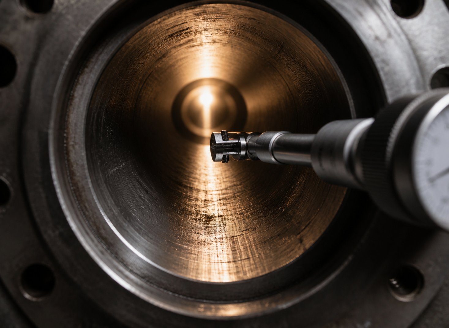
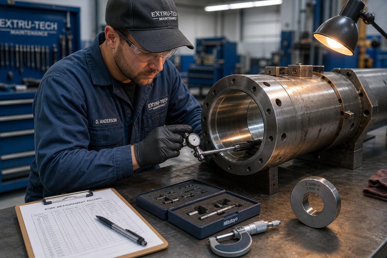
Baseline bore measurement — use calibrated bore micrometers or telescoping gauges to record the bore diameter at multiple axial positions along the barrel length. Measure at the feed zone, transition zone, metering zone, and any mixing or venting sections. Record each measurement at two perpendicular orientations (0 degrees and 90 degrees) to detect ovality. These numbers are your reference point — every future measurement gets compared to this baseline.
Scheduled bore inspections — the ideal interval depends on your process severity. A line running unfilled polyolefins through a nitrided barrel might warrant bore checks every 4,000 to 5,000 operating hours. A glass-filled nylon line could justify inspections every 1,500 to 2,000 hours. Coperion's preventive wear diagnostics program demonstrates how bore measurement combined with high-resolution video inspection enables early identification of surface damage — without requiring full process section disassembly. The screws need to be pulled and the barrels must be clean and cool, but the analysis itself can be completed during routine maintenance windows.
Wear rate trending — this is the step most plants skip, and it's the most valuable. By plotting bore diameter growth over time (or over production hours), you establish a wear rate curve for each barrel. That curve tells you not just where the bore is today, but where it will be six months from now. You can predict the point at which clearances will exceed your quality tolerance — and schedule replacement or reconditioning before that threshold is crossed.
As a practical starting point, here are the indicators maintenance teams should watch for during each inspection:
- Abrasive wear indicators: uniform bore diameter increase across the measurement zone, smooth scoring or polished appearance along the barrel floor, measurable clearance growth trending consistently over multiple inspections.
- Corrosive wear indicators: surface pitting or roughened bore texture, discoloration or staining on the liner surface, uneven diameter growth concentrated near vent ports or downstream zones where degradation byproducts concentrate.
- Adhesive wear indicators: localized scoring or gouging at specific circumferential positions, visible material transfer or buildup on the bore surface, corresponding screw flight damage (burrs, rolled edges, missing hardfacing) at the matching axial location.
- Combined wear indicators: accelerating wear rate that exceeds the expected trend for a single mechanism, bore ovality developing over time (suggesting screw deflection plus abrasion), surface roughening accompanied by measurable diameter growth.
The goal is simple: turn barrel wear from a surprise into a scheduled event. Production data — specific rate, discharge temperature, and process compensation trends — can supplement physical bore measurements, especially on larger machines where pulling extruder screws for inspection is logistically difficult. When operators start increasing screw speed, raising backpressure, or bumping up heater setpoints to hold output steady, those adjustments are indirect evidence that the gap between screw and barrel is widening.
Knowing what's wearing — and how fast — transforms barrel management from guesswork into engineering. It also shapes a question that every maintenance team eventually faces: when the bore measurements hit a critical threshold, is it smarter to recondition what you have, or replace it entirely? The answer depends on factors that go well beyond the diameter reading itself.
Barrel Thermal Management From Heating Zones to Cooling Design
Wear eats barrels from the inside. But poor thermal management can undermine barrel performance long before bore enlargement ever becomes a problem. Temperature control across the length of an extrusion screw barrel is what separates a process that produces consistent, high-quality melt from one that fights surging, degradation, and dimensional drift every shift. Yet thermal management is the most overlooked dimension of barrel specification — most discussions stop at liner material and L/D ratio without ever asking how the barrel delivers and removes heat.
Here's the reality: every barrel extruder system relies on a chain of thermal components — heaters, thermocouples, and cooling systems — working in coordination with the controller. If any link in that chain is misspecified, the process suffers. You might have the perfect liner material and the ideal L/D ratio, and still struggle with melt quality because a heater can't keep up, a thermocouple is reading the wrong temperature, or feed throat cooling is either too aggressive or too passive.
Heating Zone Layout and Band Heater Selection
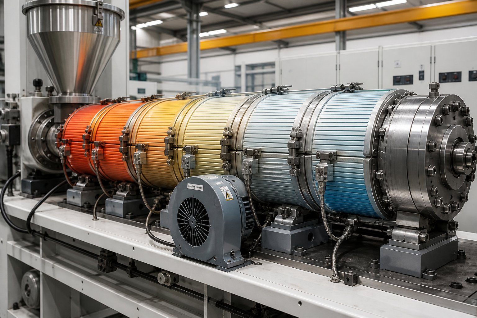
Extrusion barrels are divided into multiple independently controlled heating zones — typically four to eight, depending on barrel length and process complexity. Each zone has its own heater and its own thermocouple feeding temperature data back to a dedicated PID controller channel. This zoned architecture allows processors to create a deliberate temperature profile along the barrel: a cooler feed zone to promote solids conveying, progressively higher temperatures through the transition and melting zones, and a metering zone setpoint matched to the target melt temperature.
The heater type bolted to each zone determines how effectively and efficiently that setpoint is maintained. Three band heater families dominate the market, and each brings a fundamentally different thermal profile to the barrel.
Mica band heaters are the industry baseline. A nickel-chromium resistance ribbon is wound around a phlogopite mica core — mica serving as the dielectric insulator — and enclosed in a thin stainless steel sheath. The result is an ultra-thin profile of roughly 3 to 5 mm with extremely fast thermal response due to low thermal mass. Mica heaters transfer energy almost entirely through conduction: heat flows from the wire through the mica, through the sheath, and into the barrel wall. That conduction-only path means they demand excellent surface contact — even a 0.5 mm air gap between heater and barrel creates a thermal bottleneck that can spike wire temperature past its melting point. Maximum operating temperature sits around 340 degrees Celsius, with a watt density ceiling of approximately 3 W/cm2. For processors running commodity resins like PP, PE, and ABS at moderate temperatures, mica heaters deliver reliable performance at the lowest upfront cost.
Ceramic band heaters operate on a different principle entirely. Internal helical resistance coils thread through interlocking steatite ceramic knuckles that absorb wire heat and re-emit it as both conduction and far-infrared radiation. This dual-transfer mechanism makes ceramics far more tolerant of imperfect barrel contact. More importantly, ceramic heaters incorporate a built-in 12 mm ceramic fiber insulation blanket between the heating elements and the outer sheath. That insulation directs thermal energy inward toward the barrel and blocks radiant losses outward into the plant environment.
The performance gap is significant. Ceramic heaters handle operating temperatures up to 600 degrees Celsius with watt densities reaching 6 W/cm2 — effectively doubling the thermal capacity compared to mica. Real-world factory audits reported by heater manufacturers show that ceramic band heaters reduce power consumption by 25% to 30% compared to uninsulated mica heaters in the same application. When you're running engineering polymers like PEEK, nylon, or fluoropolymers that demand sustained high barrel temperatures, ceramic is often the only viable option — and the energy savings can offset the higher purchase price within six months of continuous operation.
Cast aluminum heaters take a different approach. A resistance element is cast directly into a machined aluminum housing that conforms precisely to the barrel's outer diameter. The aluminum body provides excellent thermal uniformity across the zone — virtually eliminating hot spots — and offers very high watt densities because the casting process ensures intimate metal-to-metal contact with zero air gaps. Cast aluminum heaters are commonly specified for large-diameter extrusion barrels, blown film lines, and applications where thermal stability matters more than rapid response. Their mass provides inherent thermal damping, smoothing out temperature oscillations that faster-responding mica or ceramic heaters can sometimes amplify in sensitive processes.
It's also worth noting that cartridge heaters appear in certain barrel designs — particularly smaller-diameter injection barrels, laboratory extruders, and specialized configurations where band heaters cannot physically fit. Cartridge heaters insert directly into drilled holes in the barrel wall, providing concentrated heating from within the metal rather than from the surface. They offer high watt density in compact form factors but are harder to replace and can create localized hot spots if hole tolerances aren't tightly controlled.
| Heater Type | Watt Density | Max Temperature | Thermal Response Speed | Energy Efficiency | Typical Application |
|---|---|---|---|---|---|
| Mica Band | Up to 3 W/cm2 | 340 degrees C (644 degrees F) | Very fast (low thermal mass) | Lower — no built-in insulation; high ambient heat loss | Commodity polymers (PP, PE, ABS); injection molding nozzles; space-constrained applications |
| Ceramic Band | Up to 6 W/cm2 | 600 degrees C (1,112 degrees F) | Moderate (thermal inertia from ceramic mass) | High — built-in 12 mm fiber insulation reduces energy use by 25-30% | Engineering plastics (PEEK, nylon, PPS); continuous 24/7 lines; high-temperature processing |
| Cast Aluminum | High (application-dependent) | Up to approximately 400 degrees C | Moderate to slow (high thermal mass provides damping) | High — precision-cast contact eliminates air gaps; good uniformity | Large-diameter barrels; blown film extrusion; applications requiring thermal stability and zone uniformity |
Cooling Channel Design and Temperature Control
Heating is only half of the thermal equation. In many processing scenarios, the barrel needs to remove heat just as precisely as it adds it — and the way cooling is designed into the barrel has a direct impact on output stability, energy efficiency, and even barrel life.
The most critical cooling location is the feed throat. Imagine what happens if the barrel wall temperature in the feed section gets too hot: polymer pellets begin softening or melting prematurely, forming a sticky layer that coats the barrel surface and screw root. This disrupts the frictional dynamics that drive solids conveying. In severe cases, material bridges across the feed opening and blocks flow entirely. Most extruders address this with water-cooled feed throat jackets — the throat section is cored with internal passages that circulate cooling water to maintain a controlled temperature well below the polymer's softening point.
What many operators get wrong, as extrusion experts at Plastics Technology have documented, is assuming that colder is always better. Excessive feed throat cooling actually reduces performance. A warmer feed throat increases frictional drag between the barrel wall and polymer — the very force that drives solids forward. Injection molding machines, which typically extend the barrel through the feed opening rather than using a separate feed throat, naturally run hotter at the resin entry point — and often achieve 10 to 20% higher specific output than extrusion extruders with identical screw designs as a result.
The optimal feed throat temperature is process-specific. It depends on screw speed, zone 1 setpoint, polymer characteristics, and throughput rate. Finding it requires systematic adjustment — varying coolant flow while monitoring specific output and head pressure stability — rather than simply maximizing water flow. Adding a dedicated thermocouple in the feed throat, with its own temperature indicator, lets you identify the ideal operating temperature and return to it quickly when process conditions change.
Beyond the feed throat, forced-air blowers mounted along the barrel provide zone-by-zone cooling for processing zones during high-speed operation or when processing low-melting-point polymers. Some barrel designs incorporate drilled water channels or cast-in cooling passages along the barrel body for more aggressive heat extraction — particularly useful in high-output compounding lines where viscous dissipation from the screw generates more heat than the process needs.
Thermocouple Placement and Temperature Accuracy
Even the best heaters and cooling systems are only as good as the temperature feedback driving the controller. And this is where a subtle but critical issue catches many processors off guard: the temperature your controller displays is not the temperature of your melt.
Barrel thermocouples are typically installed in drilled holes in the barrel wall, with the sensing junction seated at a specific depth. A thermocouple sitting close to the outer surface reads a temperature heavily influenced by the heater band. A thermocouple seated deeper — closer to the bore — reads a temperature closer to the actual barrel inner wall. But neither reads the true melt temperature.
Research from Dow's extrusion group highlights the root cause: the thermal conductivity of molten polymer is roughly 0.25 W/(m degrees C), while the surrounding carbon steel barrel wall conducts heat at 52 W/(m degrees C). That's a 200:1 ratio. The metal dominates the thermocouple reading, meaning the junction temperature reflects barrel wall temperature far more than actual melt temperature. Flush-mount probes in transfer lines can report temperatures 30 degrees Celsius or more below the bulk melt temperature if the pipe is running in a cooling mode.
For barrel zone thermocouples, the practical implication is clear: your setpoint and your actual melt temperature are not the same number. Deeper thermocouple placement reduces the error but doesn't eliminate it. Variable-depth melt probes — inserted through the barrel wall into the flowing polymer — give more accurate readings, but they're impractical in every zone. The most reliable approach combines barrel zone thermocouples for control with periodic handheld or infrared melt temperature measurements at the die face for verification.
Getting thermal management right — heater selection, cooling design, and thermocouple accuracy — creates the stable processing environment that the liner material is designed to survive in. But the barrel's thermal demands aren't universal. They shift dramatically depending on which polymer family you're processing, what fillers it contains, and what temperatures the chemistry demands. That's where barrel specification becomes truly application-specific.
Matching Barrel Type and Liner to Your Polymer Application
You know the liner options. You understand L/D ratios, wear mechanisms, and thermal management. But here's the question that ties all of those variables together: which barrel configuration should you actually specify for the resin sitting in your silo right now?
This is where many procurement decisions go sideways. A processor buys a barrel rated for "general-purpose" use, then runs 40% glass-filled PA66 through it and wonders why bore measurements are off-spec within 14 months. Or a plant invests in premium tungsten carbide-bearing bimetallic liners for a line that only processes unfilled LDPE — paying three times the price for protection it will never need. The barrel metallurgy has to match the resin you actually process, not the theoretical worst case or the easiest default.
Barrel Selection for Commodity and Engineering Polymers
Start with the polymer family, because chemistry and filler content drive roughly 70% of the barrel specification decision. Each resin group creates a distinct combination of thermal, mechanical, and chemical stress inside the bore — and the barrel must be built for that specific stress profile.
Unfilled commodity polymers — polyolefins (HDPE, LDPE, LLDPE, PP), general-purpose polystyrene, and ABS — represent the least demanding barrel environment. These resins generate minimal abrasion, produce no corrosive byproducts under normal processing conditions, and melt at moderate temperatures. A standard nitrided steel barrel delivers reliable service life at the lowest cost. For sheet extrusion and blown film lines running clean polyolefins, nitrided barrels routinely last five or more years before bore measurements warrant attention. Pairing these with a smooth-bore design and a standard three-zone plastic extrusion screw keeps capital cost and maintenance complexity low.
Unfilled engineering polymers — polycarbonate, PMMA, unfilled nylon (PA6, PA66), and PET — introduce higher processing temperatures and, in some cases, mild chemical sensitivity. PET generates acidic degradation products at elevated temperatures, and nylon absorbs moisture that can accelerate hydrolytic attack on the barrel surface if pre-drying is inadequate. For these materials, a nitrided barrel may still suffice if processing conditions are well-controlled, but many processors step up to an iron-based bimetallic liner as insurance against the slightly more aggressive thermal and chemical environment. The cost premium is modest — typically 1.8 to 2.2 times nitrided — and the extended service life usually justifies it over a multi-year production horizon.
Glass-filled and mineral-reinforced engineering plastics — this is where the barrel specification becomes non-negotiable. Running 30% glass-filled nylon or PBT through a nitrided barrel is essentially running an expiration countdown from day one. The continuous abrasive contact between glass fibers, the screw flights, and the bore surface demands a bimetallic liner with meaningful abrasion resistance. Nickel-based alloys (Ni-Cr-B-W class) offer the best balance for glass-filled nylon because they resist both the mechanical abrasion of the glass and the mild corrosive attack from nylon's moisture-related degradation products. For injection molding screws and barrels handling high-fiber compounds, tungsten carbide-bearing liners provide the armor needed to maintain bore integrity across thousands of hours of continuous cycling.
PVC and halogenated compounds — processing PVC flips the wear priority entirely from abrasion to corrosion. As PVC degrades thermally, it releases hydrochloric acid that aggressively attacks any liner with a high iron content. Standard nitrided barrels and iron-based bimetallic liners corrode rapidly under these conditions. Corrosion-resistant nickel-based alloys — often with elevated chromium and molybdenum content — are the minimum requirement. The same applies to CPVC, PVDF, and fluoropolymer processing, where hydrofluoric acid released during melt processing can destroy standard steel liners in a matter of weeks. Short L/D ratios (20:1 to 25:1) further protect the resin by minimizing residence time and thermal degradation — which simultaneously reduces the corrosive load on the barrel.
Handling Abrasive and Corrosive Compounds
The trickiest barrel specifications arise when a compound attacks on two fronts simultaneously. Imagine processing a flame-retardant glass-filled PA66 — the glass fibers grind the bore mechanically while the halogenated flame retardant releases corrosive byproducts that eat into whatever the glass doesn't reach. Neither a purely abrasion-resistant liner nor a purely corrosion-resistant one will survive this dual assault.
Highly filled compounds with glass fiber loadings above 30%, or materials containing hard mineral fillers like calcium carbonate, talc at high percentages, or wollastonite, demand tungsten carbide-containing bimetallic liners. The carbide particles embedded in the alloy matrix act as distributed armor — individual particles resist the grinding action of filler contact while the surrounding matrix maintains structural integrity. For twin screw and barrel systems used in compounding operations, where mixing intensity amplifies filler-to-metal contact, these liners are standard practice rather than upgrades.
Corrosive resins require alloys with high chromium and molybdenum content to resist chemical attack from acidic degradation products. Chromium forms a passive oxide layer that shields the underlying metal, while molybdenum enhances pitting resistance — the specific type of corrosion most common in barrel bores exposed to HCl or HF. Nickel-rich alloys with boride and carbide bases, such as Colmonoy 56 or Colmonoy 83, deliver this protection while maintaining workable hardness levels.
When abrasion and corrosion converge in the same application, the alloy selection becomes a balancing act. Pure tungsten carbide liners in an iron matrix excel at abrasion resistance but may corrode under acid exposure. Pure nickel-chromium alloys resist corrosion beautifully but lack the hardness to survive heavy glass fiber contact. The solution is a tungsten carbide-bearing alloy in a nickel-based matrix — combining carbide armor with a corrosion-resistant binder. These are the highest-cost liners in the centrifugal-cast family, but for dual-attack applications, they're the only option that delivers acceptable service life.
Matching barrel metallurgy to the resin you actually process — not just the one you planned to process — prevents premature wear and unplanned downtime.
That quote captures a reality many plants learn the hard way. Production schedules shift, new formulations get introduced, and a barrel originally specified for unfilled PP ends up running 25% glass-filled compounds three years into its service life. Every time the resin changes, the barrel's wear clock resets — sometimes dramatically faster than anyone anticipated.
Polymer-to-Barrel Selection Matrix
| Polymer Category | Recommended Liner Material | Recommended Barrel Type | Key Selection Notes |
|---|---|---|---|
| Unfilled commodity (PE, PP, PS, ABS) | Nitrided steel (38CrMoAlA or equivalent) | Smooth-bore single-screw; standard L/D 25:1-30:1 | Lowest cost option; adequate for non-abrasive, non-corrosive resins; consider grooved feed for high-output HDPE lines |
| Filled engineering plastics (GF nylon, GF PBT, mineral-filled compounds) | Bimetallic — nickel-based or tungsten carbide-bearing alloy | Smooth-bore or grooved-feed single-screw; L/D 28:1-32:1; segmented twin-screw for compounding | Fiber loading above 30% demands WC-bearing liners; match screw hardfacing to barrel liner to prevent adhesive wear |
| Corrosive resins (PVC, CPVC, PVDF, fluoropolymers) | Bimetallic — high-chromium, high-molybdenum nickel-based alloy | Short L/D (20:1-25:1) to minimize residence time; conical or parallel twin-screw for PVC compounding | Iron-based liners corrode rapidly; match barrel and screw CTE to prevent seizing at processing temperatures; mandatory feed throat cooling |
| Abrasive + corrosive (halogenated FR glass-filled compounds, recycled mixed streams) | Bimetallic — tungsten carbide in nickel-based matrix | Application-dependent; twin-screw segmented for compounding; single-screw with extended mixing zone for extrusion | Highest-cost liner tier but only viable option for dual-attack environments; shorter inspection intervals required; consider CPM tool steel for injection barrels |
A few practical points this table doesn't capture on its own. First, screw metallurgy must complement the barrel liner — a hard barrel paired with a soft screw concentrates wear on the screw, while mismatched alloys can trigger adhesive wear (galling) that damages both components. Second, the table assumes standard processing conditions. If you're running at unusually high temperatures, elevated screw speeds, or with contaminated regrind, consider stepping up one liner tier as a safety margin. Third, production volume matters: a line running 24/7 at 2,000 kg/hour accumulates more wear in three months than a job-shop line sees in two years.
For processors and procurement managers looking to evaluate specific barrel and screw components matched to these polymer families, NANHAIYA's product catalog offers a practical starting point. Their inventory spans parallel twin-screw, conical twin-screw, and single-screw configurations — covering the range from commodity processing through corrosive PVC and filled engineering plastic applications discussed throughout this section. It's one sourcing option worth reviewing alongside your existing supplier relationships, especially when matching barrel specifications to a new resin or reconfiguring a line for different materials.
Selecting the right barrel-liner-polymer combination is a front-end decision. But even the best-matched barrel eventually reaches the end of its useful life. The critical question then shifts from "what should I buy?" to "when should I act?" — and whether reconditioning or full replacement delivers better value over the next production cycle.
Barrel Lifecycle Management From Maintenance to Replacement
A perfectly matched barrel-liner-polymer combination doesn't eliminate wear — it manages the rate. Every bore surface is on a clock, and the question isn't whether it will need attention, but when. Replace too early and you're throwing away usable service life. Wait too late and you're paying for scrap, downtime, and emergency procurement at premium pricing. The sweet spot sits between those two extremes, and reaching it consistently requires a structured approach that most plants simply don't have.
Here's the uncomfortable truth: many processors manage their extruder screws and barrels the same way they manage their car tires — by feel. They wait until performance degrades noticeably, then react. That approach works until it doesn't, and the cost of "doesn't" can be staggering. A single unplanned barrel failure on a high-output line can generate tens of thousands of dollars in lost production, expedited shipping for replacement components, and scrapped material before the root cause is even confirmed.
A better model exists. It's built on three pillars: documented measurements, predictable wear trending, and a structured decision framework for reconditioning versus replacement.
Preventive Maintenance Schedules and Inspection Procedures
Effective barrel maintenance starts the moment a new barrel is installed — not months later when someone notices output has dropped. The single most valuable action you can take at installation is recording baseline bore measurements. Use calibrated bore micrometers or plug gauges to measure the inner diameter at multiple axial positions: feed zone, transition zone, metering zone, and any mixing or venting sections. Record each measurement at two perpendicular orientations to catch ovality. These numbers become your reference point for every future inspection.
From that baseline, the maintenance cadence depends on what you're processing and how hard the resin works the bore surface. A practical framework looks like this:
- Every 500 to 1,000 operating hours — monitor indirect indicators without pulling the screw. Track motor amperage trends, specific output (kg/hr per RPM), discharge melt temperature, and any process compensation adjustments operators have made. Rising amps, declining specific output, or increasing heater zone overrides all signal growing clearance between screw flights and barrel wall. As industry maintenance frameworks emphasize, measuring screw flight diameter and barrel bore at these intervals reveals replacement needs before output drops and energy costs spike.
- Every 2,000 to 4,000 operating hours — pull the screw and perform direct bore measurement during a scheduled maintenance window. Compare readings to baseline and to the previous inspection. Look for visual signs of corrosion, heat damage, scoring, or alignment-related wear patterns. Inspect heater band contact, thermocouple depth integrity, and cooling passage condition while the barrel is accessible.
- Every 6,000 to 8,000 operating hours — conduct a comprehensive assessment including bore measurement, visual inspection, heater zone performance testing, and barrel alignment verification. This is the interval where you should evaluate whether the barrel's wear trajectory will carry it safely through the next production cycle or whether intervention is needed.
These intervals assume moderately demanding applications — filled engineering plastics at standard throughputs. Lines running highly abrasive compounds or corrosive resins should compress these windows. A glass-filled nylon line might justify bore checks every 1,500 hours. A clean polyolefin operation running through nitrided barrels might safely extend to 5,000-hour intervals. The key is consistency: measurements taken sporadically are nearly useless. Measurements taken at regular intervals become predictive.
Documenting wear rates over time is what transforms raw diameter readings into actionable intelligence. Plot bore diameter growth on a simple chart — operating hours on the x-axis, bore diameter on the y-axis. You'll typically see a gradual, roughly linear increase during the barrel's useful life. That slope is your wear rate, and it tells you exactly how many operating hours remain before the bore exceeds your quality tolerance. When the slope suddenly steepens — indicating accelerating wear — you know the liner's effective hardened layer is breached, and remaining life is short.
This trending approach also catches problems that single measurements miss. A barrel that gained 0.05 mm over the first 4,000 hours but 0.15 mm over the next 4,000 hours is telling you something changed — a new resin, contaminated feedstock, a screw metallurgy mismatch, or a thermal management issue accelerating wear. The trend reveals the shift before part quality deteriorates enough for operators to notice.
Reconditioning vs. Replacement Decision Framework
When bore measurements approach your process tolerance, two paths open: recondition the existing barrel or replace it entirely. Each option carries its own cost profile, lead time, performance expectation, and risk — and the right choice depends on more than just the sticker price.
Reconditioning options include reboring and re-nitriding (machining the bore to a slightly larger diameter and re-hardening the surface), bimetallic re-sleeving (centrifugally casting a new alloy liner inside the existing shell), and in some cases, honing or polishing to restore surface finish without changing bore dimensions. Reconditioning is viable when wear is mild to moderate — typically when bore enlargement hasn't exceeded the limits of available oversize screw configurations. A rebored barrel paired with a new oversize injection screw or extrusion screw can restore near-original clearances at a fraction of the cost of full replacement.
The economics shift sharply, though, when wear is severe. A barrel with deep scoring, corrosion pitting, or bore enlargement beyond the maximum available oversize screw diameter is not a reconditioning candidate — the structural integrity of the remaining wall thickness may be compromised, and the performance of a reconditioned barrel under these conditions will fall short of what a new component delivers. Similarly, if the bimetallic liner is worn through to the base steel in critical zones, re-sleeving may not bond properly to the degraded substrate. As repair specialists note, full replacement restores original performance, while repair extends life temporarily — and that distinction matters when you're counting on the barrel to run reliably for the next 12 to 24 months.
To make this decision systematically rather than intuitively, use the following framework:
- Measure current bore wear — record diameter readings at all axial positions and compare to baseline. Quantify the total material loss and identify whether wear is uniform or localized.
- Calculate the wear rate trend — divide bore growth by operating hours since the last measurement to establish the current wear rate. Compare it to historical rates. An accelerating trend signals that remaining life is shorter than a simple linear projection would suggest.
- Estimate remaining service life — project when bore dimensions will exceed your process tolerance based on the current wear rate. If that date falls within the next planned maintenance cycle, act now. If it falls well beyond, you have time to plan.
- Compare reconditioning cost to replacement cost — obtain quotes for both options. Factor in not just component price but also lead time, installation labor, and any required screw modifications (oversize screw for a rebored barrel, for example). A used twin screw extruder barrel that has been reconditioned may cost 40 to 60% of a new one — but if it delivers only 50% of the expected service life, the per-hour economics favor new.
- Factor in downtime risk — a reconditioned barrel that fails prematurely forces another unplanned shutdown. Weigh the probability of early failure against the cost savings of reconditioning. For 24/7 production lines where unplanned stops cost thousands of dollars per hour, the risk premium of a reconditioned barrel often tips the scale toward replacement.
- Evaluate whether processing requirements have changed — if you've shifted to a more abrasive or corrosive resin since the barrel was originally specified, reconditioning to the original specification puts you right back where you started. This is the ideal moment to upgrade the liner material to match current and anticipated future processing demands.
The cheapest barrel decision is rarely the lowest purchase price — it is the option that minimizes total cost per kilogram of quality output.
That total-cost-of-ownership perspective is what separates strategic barrel management from reactive part-swapping. Studies analyzing wear economics in high-shear extrusion environments consistently demonstrate that the lowest-cost material isn't the cheapest upfront — it's the one that provides equivalent or superior lifespan at a lower cost-per-operating-hour. A barrel liner that costs twice as much but lasts three times as long cuts your effective barrel cost by a third. Add in avoided downtime, reduced scrap, and lower energy consumption from tighter bore clearances, and the gap widens further.
One practical tip that often gets overlooked: keep a reconditioning-versus-replacement log for every barrel in your plant. Record the decision made, the cost of each option at the time, the actual service life achieved after the intervention, and the total production volume processed. Over two or three barrel cycles, this data builds a plant-specific cost model that takes the guesswork out of future decisions. Your maintenance team stops debating opinions and starts referencing evidence.
This lifecycle discipline — baseline measurement, scheduled inspection, wear trending, and structured replacement decisions — is what prevents the two most expensive barrel mistakes: replacing too soon and replacing too late. It also creates a foundation for continuous improvement, because every barrel cycle generates data that refines the next specification, sharpens the next inspection interval, and strengthens the business case for the right liner material at the right time.
Actionable Takeaways for Smarter Barrel Decisions
Every section of this guide points toward the same conclusion: barrel performance is not a matter of luck. It's engineered through deliberate choices — liner material matched to polymer chemistry, L/D ratio sized to thermal and rheological requirements, thermal management configured for the actual process, and wear monitored with enough discipline to predict problems before they become emergencies. The processors who get this right don't just extend barrel life. They protect part quality, reduce energy waste, and turn maintenance from a cost center into a competitive advantage.
Key Principles for Barrel Selection and Performance
If you take one thing from this article, let it be this: a screw extruder is a system, and specifying any single component in isolation guarantees a mismatch somewhere. The barrel, screw, heaters, cooling system, and controller all interact. Change one variable — a new resin, a different filler loading, a higher throughput target — and the ripple effects touch every other component in the chain.
That said, the barrel specification itself rests on a handful of critical decision points that, when handled correctly, eliminate the most common and most expensive mistakes:
- Match liner material to your actual polymer chemistry and filler content. A nitrided barrel is perfectly adequate for unfilled polyolefins. It's a liability for glass-filled nylon. And it's a fast-track to failure for PVC. Don't over-specify for resins you might run someday, but don't under-specify for the ones you're running right now.
- Select L/D ratio based on processing requirements and thermal sensitivity. Longer barrels improve melt homogeneity and mixing capacity for semi-crystalline and filled materials. Shorter barrels protect heat-sensitive resins like PVC and certain bioplastics from degradation. Neither choice works in a vacuum — the plastic extruder screw geometry must be designed to use the available barrel length effectively.
- Choose barrel type based on throughput targets and material characteristics. Smooth-bore designs handle the broadest range of commodity applications at the lowest cost. Grooved-feed barrels unlock higher throughput for high-viscosity resins like HDPE but demand harder liners and aggressive feed throat cooling. Segmented twin-screw barrels provide the modularity that compounding and reactive extrusion applications require.
- Specify barrel and screw together as a matched pair. Screw extruders perform as systems. A hard barrel liner paired with a soft screw concentrates wear on the screw. Incompatible metallurgies invite adhesive wear. A long barrel with a basic three-zone screw wastes the extra processing length. Every barrel decision implies a screw decision — and vice versa.
- Design thermal management around the process, not just the polymer's melting point. Heater type, zone layout, cooling design, and thermocouple placement all shape the melt temperature profile that the barrel delivers. Ceramic band heaters cut energy costs by 25 to 30% on high-temperature lines. Feed throat cooling requires optimization, not maximization. And the temperature on your controller screen is not the temperature of your melt — verify it independently.
Building a Long-Term Barrel Management Strategy
Selection gets you started. Management keeps you running. The difference between a plant that replaces barrels on evidence and one that replaces them on gut feeling is measured in tens of thousands of dollars per line per year — in avoided downtime, reduced scrap, and smarter capital allocation.
Building that evidence base doesn't require sophisticated technology. It requires consistency. Establish baseline bore measurements at installation. Inspect at regular intervals matched to your process severity. Plot wear rates over time. And when the data says a barrel is approaching its limit, use a structured reconditioning-versus-replacement framework that weighs total cost of ownership — not just purchase price.
The processors who manage barrels proactively share a few habits worth adopting:
- They record baseline bore measurements on every new barrel before the first production run.
- They track wear rates over time and use trend data to predict replacement timing — turning emergency shutdowns into planned maintenance events.
- They evaluate reconditioning versus replacement using total cost per kilogram of quality output, not just upfront component cost.
- They reassess barrel specifications whenever the resin or formulation changes, recognizing that a barrel matched to yesterday's polymer may be mismatched to tomorrow's.
- They treat barrel and screw as an interdependent system in every specification, procurement, and maintenance decision.
- They maintain a reconditioning-versus-replacement log for each barrel, building plant-specific cost models that sharpen every future decision.
These practices aren't aspirational. They're operational discipline — the kind that compounds over multiple barrel cycles into measurable improvements in uptime, quality, and cost efficiency.
For processors evaluating barrel and screw components across extrusion and injection molding platforms, NANHAIYA's product catalog provides a starting point for comparing configurations and specifications. Their range covers single-screw, parallel twin-screw, and conical twin-screw components — relevant to the full spectrum of barrel types and polymer applications discussed throughout this article. Whether you're sourcing a replacement barrel for a commodity polyolefin line or specifying corrosion-resistant components for PVC compounding, reviewing available options alongside your existing supplier relationships helps ensure the next barrel you install is the right one — not just the available one.
Frequently Asked Questions About Extruder Barrels
1. How long do extruder barrels typically last before needing replacement?
Barrel lifespan varies dramatically based on liner material and the polymer being processed. A nitrided steel barrel running unfilled polyolefins can last five or more years, while the same barrel processing 30%+ glass-filled nylon may wear out in 12 to 18 months. Bimetallic barrels with tungsten carbide-bearing liners can last two to seven times longer than nitrided barrels under abrasive conditions. The most reliable way to predict replacement timing is to record baseline bore measurements at installation, conduct scheduled bore inspections every 2,000 to 4,000 operating hours, and plot wear rate trends over time. This data-driven approach lets maintenance teams forecast when bore clearances will exceed process tolerances and schedule replacements proactively rather than reactively.
2. What is the difference between a nitrided barrel and a bimetallic barrel?
A nitrided barrel uses a single alloy steel body with a nitrogen-diffused hardened surface layer roughly 0.4 to 0.6 mm deep, achieving hardness around 950 to 1,100 HV. It works well for non-abrasive, non-corrosive commodity resins at a low cost. A bimetallic barrel separates structural and wear-resistant functions: a steel outer shell provides rigidity while a centrifugally cast alloy liner — 1.5 to 3.0 mm thick — handles polymer contact. This gives bimetallic barrels five to six times the effective wear depth of nitrided barrels. Bimetallic liners come in iron-based, nickel-based, and tungsten carbide-bearing alloy families, each targeting different combinations of abrasive and corrosive wear. The cost premium ranges from 1.8x to 3.0x over nitrided, but extended service life and reduced downtime often deliver a lower total cost per operating hour.
3. How do I choose the right L/D ratio for my extruder barrel?
L/D ratio selection depends on the polymer's thermal sensitivity, the level of mixing required, and your throughput targets. Longer ratios (30:1 to 36:1) provide more processing length for gradual melting, thorough mixing, and melt homogenization — ideal for semi-crystalline polymers like PET and PA66 or heavily filled compounds that need extended mixing zones. Shorter ratios (20:1 to 24:1) reduce residence time, protecting heat-sensitive materials like PVC and certain bioplastics from thermal degradation. Vented configurations typically demand longer L/D specs because each vent zone consumes 5 to 8 L/D of barrel length. Critically, barrel length and screw design must be specified together — a long barrel paired with a basic three-zone screw wastes the extra processing length, while a short barrel limits the screw designer's ability to stage functional zones effectively.
4. When should I recondition an extruder barrel versus replacing it entirely?
Reconditioning — including reboring, re-nitriding, or bimetallic re-sleeving — is economically viable when wear is mild to moderate and bore enlargement hasn't exceeded the limits of available oversize screw configurations. A structured decision framework helps: measure current bore wear, calculate the wear rate trend, estimate remaining service life, compare reconditioning cost to replacement cost (including lead time and screw modifications), factor in the downtime risk of premature failure, and evaluate whether your processing requirements have changed since the barrel was originally specified. Full replacement is the better choice when wear is severe, the liner is worn through to base steel, or your resin portfolio has shifted to more demanding materials that require an upgraded liner. Always evaluate total cost per kilogram of quality output rather than upfront purchase price alone.
5. What type of extruder barrel liner is best for processing PVC?
PVC processing demands corrosion-resistant nickel-based alloy liners with elevated chromium and molybdenum content. As PVC degrades thermally, it releases hydrochloric acid (HCl), which aggressively attacks any barrel liner with a high iron matrix — including standard nitrided steel and iron-based bimetallic liners. Nickel-rich alloys resist this chemical attack while maintaining adequate hardness for mechanical wear resistance. Barrel geometry also matters: short L/D ratios of 20:1 to 25:1 minimize residence time, reducing both thermal degradation of the PVC and the corrosive load on the barrel. Conical or parallel twin-screw barrels are commonly specified for PVC compounding. Processors exploring barrel options for PVC lines can review corrosion-resistant configurations through suppliers like NANHAIYA at nhyscrews.com/products, which offers components across conical twin-screw and parallel twin-screw platforms suited to corrosive resin applications.
Written by
Nanhaiya Technical Team
Zhoushan Nanhaiya Plastic Machinery Co., Ltd.
The Nanhaiya technical team supports screw and barrel manufacturing projects through application review, technical communication, custom manufacturing coordination, and production and quality control.
Discuss Your Application
Related Articles
More insights on screw barrel technology and plastics processing.

What Nobody Tells You About Screw Barrel For Plastic Machine Design
Oct 10, 2026
Learn how screw barrel for plastic machine design affects melt quality, throughput, and wear life. Covers geometry, resin matching, troubleshooting, and sourcing.
Read Article
Single Screw Extruder for Sheet: Stop Guessing, Start Specifying
Oct 9, 2026
Learn how to specify a single screw extruder for sheet production. Covers screw geometry, resin-specific processing, troubleshooting, and maintenance best practices.
Read Article
PE Pipe Extruder Machine: What Datasheets Won't Tell You
Oct 9, 2026
Learn how a PE pipe extruder machine works, key specs explained, material grade selection, maintenance tips, and buyer guidance beyond the datasheet.
Read ArticleLooking for something else?
Search by material, symptom or product and jump straight to the relevant page.
These are navigation suggestions based on keyword matching — not a quotation, not a delivery commitment, and not a substitute for engineering review. Final specification is confirmed by our engineers against your drawings and processed material.
Need help with screw barrel selection?
Share your machine model, processed material and application. Our team can help with pricing and technical support.