

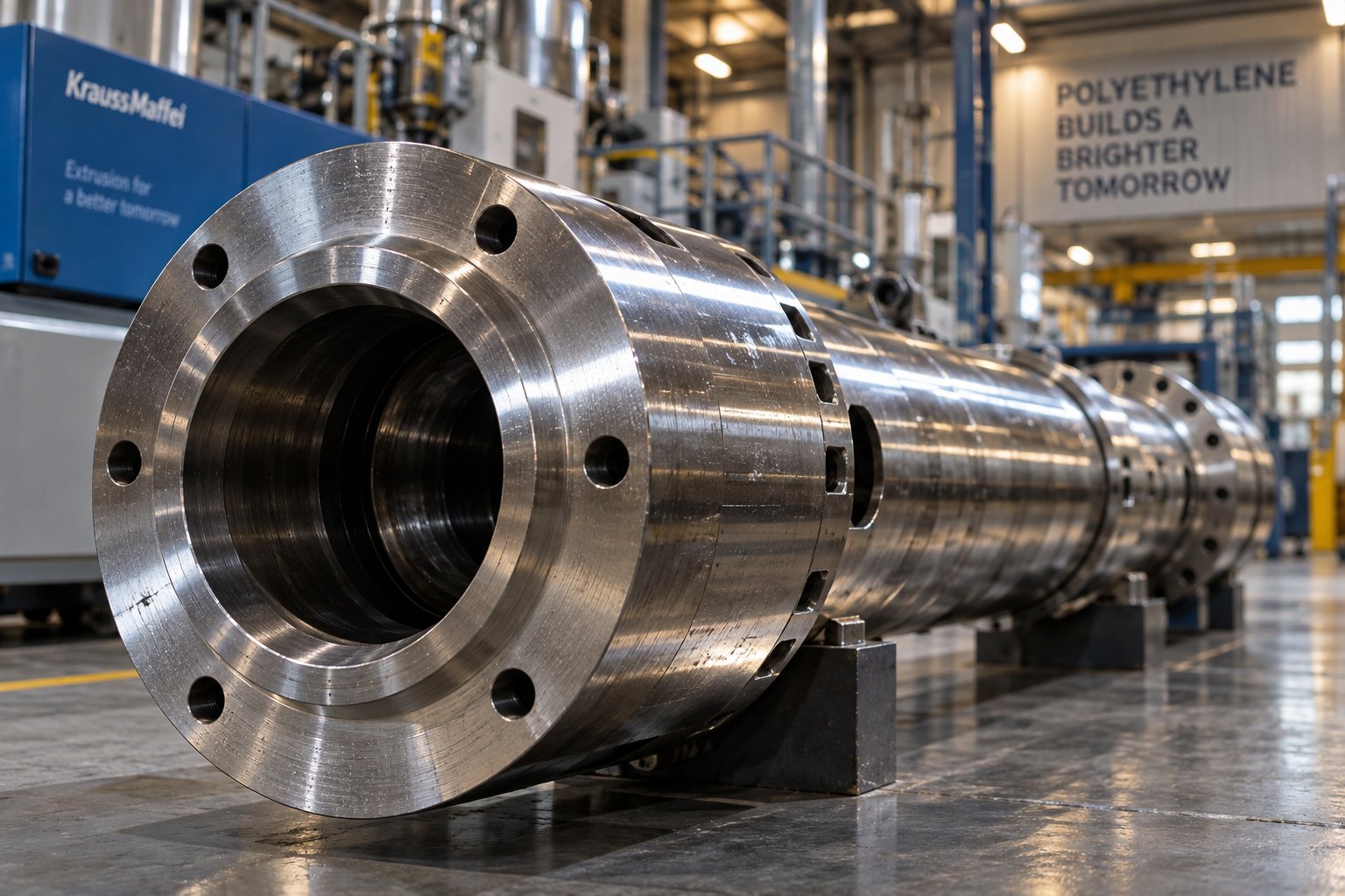
Why Polyethylene Demands a Purpose-Built Extruder Barrel
Imagine running your PE line at full capacity, yet still fighting gel counts, surging output, or dull film clarity. The problem might not be your resin, your screw speed, or even your operator. It might be the barrel itself — engineered for generic thermoplastic processing rather than the specific demands of polyethylene.
Most barrel selection guides treat all polymers as interchangeable. They're not. PE's semi-crystalline structure, its sharp melting behavior in HDPE versus the broader melt range seen in LDPE and LLDPE, and its high-throughput processing demands create a unique set of engineering challenges that generic guidance simply overlooks.
What Is an Extruder Barrel for PE Processing
An extruder barrel for PE is the cylindrical steel housing that contains the screw, applies controlled thermal energy through heated and cooled zones, and withstands the mechanical and chemical stresses involved in melting and conveying polyethylene resin. Together, extruder screws and barrels form the heart of the plasticating unit — and as industry experts emphasize, their original clearances are usually minimal (around 0.001 in. per side, per inch of diameter) to achieve proper heat transfer and shear. When those clearances are wrong — or when the barrel isn't designed for PE in the first place — melt quality suffers immediately.
Why PE Requires Specialized Barrel Engineering
Polyethylene presents a trio of barrel design challenges that set it apart from amorphous polymers like polystyrene or ABS. First, PE's high abrasion potential — especially with mineral-filled or recycled grades containing contaminants — accelerates wear on both the extruder barrel and screw flights. Second, PE operates within a relatively narrow optimal melt temperature window, making precise thermal management essential. Third, PE lines frequently run at high volumetric output rates, placing sustained mechanical stress on the extruder feed barrel and its internal surfaces.
A barrel optimized for PE processing directly affects film clarity, pipe wall uniformity, and surface finish of the final product — making it one of the most consequential equipment decisions a plant engineer can make.
These factors mean that barrel selection isn't just a procurement checkbox. It's a critical lever for line performance, product quality, and long-term equipment longevity. Yet most available resources treat barrel engineering as polymer-agnostic, leaving plant engineers, extrusion operators, and procurement managers without PE-specific guidance.
That gap matters more than you might think — because PE's unique melt behavior doesn't just influence which barrel you choose. It shapes every design parameter inside it, starting with thermal management and L/D ratio.
How PE Melt Behavior Shapes Barrel Design Parameters
Here's a question most barrel guides never ask: why should a barrel designed for HDPE pipe look fundamentally different from one running LDPE blown film — even though both are polyethylene? The answer lies in PE's semi-crystalline molecular architecture and how dramatically it affects melting behavior. Get the barrel design wrong for the specific PE grade you're running, and you'll battle unmelt particles, temperature surging, and degraded output quality no matter how perfectly you dial in your process settings.
How PE Melt Rheology Dictates Barrel Thermal Management
Unlike amorphous polymers such as polystyrene or ABS — which soften gradually over a wide temperature range — polyethylene transitions from solid to melt through a distinct crystalline melting process. This is where barrel thermal management becomes critical. Too little thermal energy leaves unmelted crystalline regions in the melt stream, producing gels, fish-eyes, and pressure instability. Too much heat breaks polymer chains, degrades mechanical properties, and can cause discoloration or off-gassing.
What makes PE especially challenging is that different grades within the same polymer family behave very differently during melting. HDPE, with its highly linear chain structure and minimal branching, achieves a relatively high degree of crystallinity. Research into polyethylene crystallinity and rheology confirms that crystallinity scales with HDPE content in blends, and that HDPE forms larger, more uniform crystallites compared to branched PE grades. In practical terms, this means HDPE exhibits a sharper, more defined melting point — the crystallites resist melting until a threshold temperature, then transition rapidly. The extruder screw barrel must deliver enough thermal energy in a relatively short transition window to fully melt these crystallites without overshooting into degradation territory.
LDPE and LLDPE tell a different story. LDPE's long-chain branching disrupts crystalline packing, producing smaller, less uniform crystallites that melt over a broader temperature range. LLDPE falls somewhere in between — its short-chain branches reduce crystallinity compared to HDPE, but its linear backbone still allows moderate crystalline order. DSC studies show that HDPE-LDPE blends often display two separate melting peaks, indicating distinct crystalline populations, while HDPE-LLDPE blends tend toward a single melting peak consistent with co-crystallization. For the screw extruder barrel, this translates to a fundamental design difference: HDPE demands aggressive, tightly controlled thermal input concentrated in the transition zone, while LDPE and LLDPE benefit from a more gradual, distributed heating profile.
You'll notice this distinction matters enormously in practice. Run an LDPE resin through a barrel thermally optimized for HDPE, and you risk overheating a polymer that didn't need that concentrated energy input. Reverse the scenario, and HDPE pellets may exit the metering zone with unmelted particles embedded in the melt — a recipe for rejected product.
L/D Ratio and Feed Section Design for PE Grades
The length-to-diameter (L/D) ratio of an extruder barrel determines how much residence time and working length the polymer gets for melting, mixing, and homogenization. PE processing typically requires longer L/D ratios — commonly in the range of 24:1 to 33:1 — compared to many other thermoplastics. Why? Because PE's semi-crystalline structure demands both sufficient energy input to fully melt the crystalline phase and enough barrel length to homogenize the resulting melt into a uniform temperature and viscosity profile.
Shorter L/D ratios might work for amorphous polymers that soften predictably, but with PE, cutting the barrel short often means incomplete melting or poor melt homogeneity. This is especially true for HDPE, where that sharp melting transition requires adequate barrel length in the transition zone to convert all crystallites without creating localized hot spots. LDPE and LLDPE, with their broader melting ranges, are somewhat more forgiving on L/D — but still benefit from longer ratios when processing at high throughput rates or when melt uniformity is critical for end-product quality.
Feed section geometry is another PE-specific design consideration that often gets overlooked. PE pellets have distinct bulk density and friction characteristics that affect how efficiently they're conveyed from the hopper into the barrel bore. The feed zone bore must be designed to maintain consistent solids conveying — if pellets slip or bridge in the feed section, you'll see output fluctuations and pressure instability downstream. HDPE pellets, being denser and harder than LDPE pellets, interact differently with the barrel wall surface, influencing how deep the feed section channels need to be and how the barrel surface finish is specified.
The transition zone — where solid PE pellets are compressed and converted into melt — also requires grade-specific barrel design thinking. HDPE's sharper melting transition means the compression happens more abruptly, demanding a barrel and extruder screw geometry that can handle the sudden change in material state without creating excessive pressure spikes. LDPE's broader melting range allows a more gradual compression transition.
Here are the key barrel design parameters directly influenced by PE melt behavior:
- L/D ratio: Longer ratios (24:1 to 33:1) ensure complete crystallite melting and thorough melt homogenization across PE grades
- Feed zone length: Must accommodate PE pellet bulk density and friction characteristics to maintain stable solids conveying
- Compression ratio compatibility: The barrel's internal geometry must match the screw's compression ratio to manage PE's solid-to-melt transition without pressure surging
- Transition zone taper: HDPE's abrupt melting behavior favors a different transition zone profile than LDPE's gradual softening, affecting both barrel bore geometry and thermal zone layout
These parameters don't exist in isolation — they interact with each other and with the extruder screw design to determine whether your PE line delivers consistent, high-quality melt or fights you on every run. And the barrel material you choose to withstand PE's processing stresses plays an equally critical role in long-term performance.
Barrel Material Selection Optimized for PE Grades
Your barrel's geometry, L/D ratio, and thermal zone layout may be perfectly dialed in for polyethylene — but none of that matters if the barrel's internal surface can't survive the punishment PE processing dishes out over thousands of production hours. The material lining the bore is what stands between a well-performing extrusion barrel and one that's quietly degrading your melt quality through accelerating wear, increasing screw-to-barrel clearance, and introducing metallic contamination into your product.
Choosing the right barrel construction material for PE isn't a one-size-fits-all decision. The answer depends heavily on which PE grade you're running, whether fillers or recycled content are involved, and how aggressively your line operates. Yet most barrel material guides lump all polymers together — leaving PE processors to guess which liner chemistry actually matches their application. Let's fix that.
Nitrided Steel Barrels for Standard PE Processing
For many general-purpose PE extrusion lines running clean, virgin resin without mineral fillers or abrasive additives, nitrided steel extruder barrels provide a practical and cost-effective solution. The nitriding process — typically gas nitriding — diffuses nitrogen atoms into the steel surface at elevated temperatures, creating a hard wear-resistant layer. According to IMS Company's barrel material guidelines, this process produces surface hardness well above 60 Rc, with an effective hardened depth typically ranging from 0.007" to 0.015" depending on cycle duration.
A common substrate for nitrided extrusion barrels is Nitralloy 135M, a steel specifically formulated with aluminum, chromium, and molybdenum — elements that readily combine with nitrogen to form extremely hard nitride compounds at the surface. This makes the bore resistant to the moderate abrasion that virgin LDPE, LLDPE, and HDPE pellets generate during normal conveying and melting.
Sounds like a straightforward choice, right? Here's the catch. That nitrided layer is finite. Once the hardened surface wears through — which happens faster than many operators expect when running at high screw speeds or processing PE grades with even modest filler content — wear accelerates dramatically because the softer base steel beneath offers far less resistance. As industry manufacturers note, nitrided components are not recommended for abrasive or corrosive resins precisely because the protective layer cannot resist wear over extended production campaigns under those conditions.
For PE processors, this means nitrided barrels work well in a defined operating envelope: virgin PE, moderate throughput, and no corrosive byproducts. Step outside that envelope — add calcium carbonate filler, introduce post-consumer recyclate, or push output rates significantly higher — and you'll find the nitrided layer wearing through much sooner than planned, silently widening the bore-to-screw clearance and degrading melt quality long before scheduled maintenance.
Bimetallic Barrel Liners for Demanding PE Applications
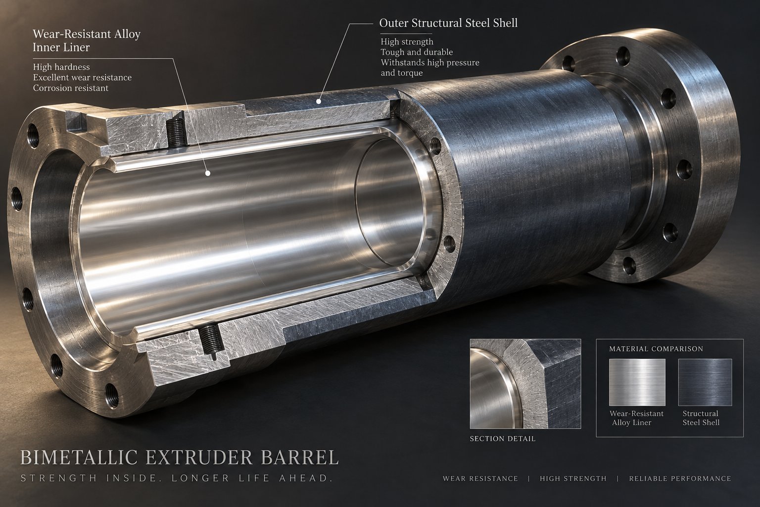
When your PE application involves filled compounds, recycled feedstock with contaminants, or sustained high-output production, bimetallic barrel construction becomes the more appropriate — and often more economical — long-term choice. Bimetallic extrusion barrels feature a wear-resistant alloy metallurgically bonded to the inner bore surface through a centrifugal casting process, creating a liner typically 0.040" to 0.080" thick. That's substantially more sacrificial material protecting the bore compared to a nitrided layer measured in thousandths of an inch.
The critical decision isn't simply "bimetallic or not" — it's which alloy chemistry matches your specific PE processing challenge. Three primary alloy families cover the spectrum of PE wear scenarios:
Iron-boron (nickel-boron) alloys represent the standard bimetallic option. These alloys deliver good abrasion resistance with a low friction coefficient, making them suitable for PE compounds with moderate filler levels or PE lines running at sustained high output. Think of this as the workhorse liner — significantly more durable than nitrided steel for PE grades containing up to roughly 30% mineral fillers, at a reasonable cost premium.
Nickel-based alloys with high chromium content address a different problem. When you're processing recycled PE — especially post-consumer material from mixed waste streams — the concern isn't just physical abrasion. Residual printing inks, adhesive residues, and moisture trapped in recycled PE flake can generate corrosive off-gassing during melting. These acidic byproducts attack the barrel bore chemically, a failure mode that abrasion-resistant alloys alone won't prevent. Cobalt-nickel alloys with elevated chromium content provide the corrosion resistance needed to survive this chemical environment while still maintaining solid wear performance.
Tungsten carbide liners sit at the top of the performance pyramid. When PE compounds carry high percentages of glass fiber, calcium carbonate above 30-40%, or other aggressively abrasive fillers, tungsten carbide provides exceptional resistance that dramatically extends barrel service life. The tradeoff is cost — these liners carry a significant price premium — but for production lines where barrel replacement means extended downtime and lost output, the total cost of ownership calculation often favors the investment.
Imagine running a recycling line processing contaminated post-consumer HDPE at high throughput. You're facing simultaneous abrasion from particulate contaminants and corrosion from volatile off-gassing. Neither a nitrided barrel nor a standard iron-boron bimetallic liner addresses both threats. This is where alloy selection becomes a true engineering decision — one that directly determines how many production hours you'll get before bore wear forces a barrel change.
| Material Type | Best PE Application Match | Abrasion Resistance Level | Corrosion Resistance Level | Relative Cost Tier |
|---|---|---|---|---|
| Gas-Nitrided Steel (e.g., Nitralloy 135M) | Virgin PE without fillers; moderate-output lines | Moderate (surface-depth limited) | Low | $ (Lowest) |
| Iron-Boron / Nickel-Boron Bimetallic | PE with moderate fillers (up to ~30%); high-output virgin PE | Good | Low to Moderate | $$ (Mid-Range) |
| Nickel-Chromium / Cobalt-Nickel Bimetallic | Recycled PE with corrosive off-gassing; PE with corrosive additives | Good | High | $$$ (Upper Mid-Range) |
| Tungsten Carbide Bimetallic | Heavily filled PE (>30% mineral); glass-fiber-reinforced PE | Excellent | Moderate | $$$$ (Premium) |
One principle bears repeating: barrel material selection is one of the highest-impact decisions affecting PE line total cost of ownership. A cheaper barrel that wears out in half the time doesn't save money — it costs more in replacement parts, unplanned downtime, scrap product from widening clearances, and the labor hours spent troubleshooting melt quality issues that are really barrel wear in disguise. The smartest PE processors evaluate liner material not on purchase price alone, but on the cost-per-production-hour over the barrel's full service life.
Selecting the right alloy protects the bore — but the barrel's performance also depends on how precisely it manages heat. And for PE, thermal control is where barrel engineering gets especially demanding.
Heating and Cooling Zone Configurations for PE Processing
Picture this: you've selected the right liner material, matched your L/D ratio to your PE grade, and installed a brand-new barrel. Yet your blown film still shows haze, your pipe wall thickness wanders, or your output surges unpredictably every few minutes. What's going wrong? In many PE extrusion lines, the culprit isn't the barrel itself — it's how the barrel manages heat. A PE extrusion barrel that can't deliver precise, zone-by-zone thermal control is fighting the polymer's own physics every second of every production run.
PE's semi-crystalline nature creates a narrower acceptable melt temperature window than most amorphous thermoplastics. Consider the numbers: LDPE melts between roughly 221-239°F (105-115°C), while HDPE melts at 266-279°F (130-137°C). Compare that to polycarbonate's wide 446-500°F range or PVC's massive 212-500°F window. For PE, you're working within a tight band where just a few degrees too cold leaves unmelted crystallites in the melt stream, and a few degrees too hot triggers thermal degradation — chain scission, discoloration, and loss of mechanical properties. That narrow margin is why extruder barrel heating demands more attention in PE processing than in most other polymer families.
Barrel Heating Zone Layout for PE Extrusion
Extrusion barrels divide into multiple independently controlled heating zones, and each zone plays a distinct role in converting PE pellets into a uniform, processable melt. The typical progression — feed zone, compression (transition) zone, and metering zone — follows the same general layout used for other thermoplastics, but PE requires a fundamentally different temperature philosophy within that layout.
Feed zone: This is where many PE processors get into trouble. The feed section must stay relatively cool — deliberately below the polymer's melting point. Why? Because solids conveying in the feed zone depends on friction between the PE pellets and the barrel wall. If the barrel extruder feed section runs too hot, pellet surfaces begin to soften and stick, destroying the friction differential that pushes material forward. The result is inconsistent feeding, output fluctuations, and the bridging problems that industry experts identify as one of the most common and costly process disruptions. For PE specifically, the relatively low melting points compound this risk — there's less thermal headroom between ambient temperature and the point where pellets start getting tacky.
Transition (compression) zone: Here, the barrel applies gradual thermal energy to begin melting PE's crystalline structure. The key word is "gradual." HDPE's sharp crystalline melting transition means that if too much heat is applied too quickly, you get a sudden phase change that can create pressure spikes and uneven melt development. LDPE and LLDPE, with their broader melting ranges, tolerate a slightly more aggressive thermal ramp — but still benefit from progressive, controlled heat input through the transition zone. This is where the difference between HDPE and LDPE barrel zone profiles becomes especially pronounced, despite both being polyethylene.
Metering zone: By this stage, the polymer should be fully molten. The metering zone's thermal job is straightforward in principle but demanding in practice: maintain consistent melt temperature with minimal variation across the entire cross-section of the melt stream. For PE film applications, even small temperature gradients translate directly into gauge inconsistency and optical defects. For PE pipe, uneven metering zone temperatures show up as wall thickness variation.
What trips up many operators is assuming that HDPE and LDPE can share the same zone temperature profile. They can't. HDPE typically requires higher set points in the transition and metering zones to fully melt its higher-crystallinity structure, while LDPE — with its lower melting point and broader transition — often performs best with a flatter, more moderate profile. Running LDPE at HDPE temperatures risks thermal degradation; running HDPE at LDPE temperatures risks pushing unmelt particles into the die.
Cooling Channels and Thermal Response in PE Barrels
Heating gets the attention, but for PE processing, barrel cooling is equally critical — and often more neglected. Effective extruder barrel cooling zones serve two essential functions: they prevent heat from migrating into areas where it's unwanted, and they give the control system the ability to actively remove excess thermal energy generated by mechanical shear.
The most critical cooling location in any PE barrel is the feed throat area. PE's relatively low melting points make it especially prone to premature melting in the feed section. When PE pellets begin to melt before they've been conveyed far enough into the barrel, the softened material can smear across the screw root and barrel wall, forming a melt film that destroys solids conveying. The symptoms are familiar to anyone who's run PE lines: surging output, erratic screw torque, and in severe cases, complete feed blockage — what processors call "bridging." As process troubleshooting experts emphasize, a bridged feed throat isn't just an inconvenience; it creates dangerous pressure buildup that can blow plastic and even the hopper upward.
Cooling channel design directly affects how quickly the barrel can respond to thermal disturbances. Channels positioned close to the bore surface provide faster thermal response but may weaken the barrel wall structurally. Channels placed farther from the bore improve structural integrity but slow the cooling response time — a real problem when PE's low thermal conductivity means heat buildup can develop rapidly in the transition zone, especially at high screw speeds. The flow rate through these channels matters too: insufficient coolant flow creates temperature gradients along the barrel length, while excessive flow can overcool the barrel wall and impair melting efficiency.
For PE specifically, cooling medium selection also deserves consideration. Water-based cooling provides excellent heat transfer capacity and fast response for the feed throat and forward barrel zones. Oil-based cooling, while offering less thermal conductivity, provides a wider operating temperature range for zones where temperatures need to be held above water's boiling point. The choice depends on the specific PE grade, the zone location, and the line's throughput demands.
Here are the most impactful thermal management best practices for PE extrusion barrels:
- Feed throat cooling: Maintain aggressive, consistent cooling at the feed throat to prevent premature PE pellet softening, bridging, and conveying instability — this is the single most important cooling zone for PE
- Zone-by-zone temperature profiling: Set each barrel zone independently based on the specific PE grade being processed; avoid applying generic "flat" profiles or borrowing settings from other polymer families
- Thermocouple placement depth: Ensure temperature sensors are positioned at a consistent depth relative to the bore surface to get accurate readings of actual barrel wall temperature rather than heater band temperature — shallow placement gives faster response, while deep placement better represents melt-contact conditions
- Cooling medium selection: Use water-based cooling for feed throat and lower-temperature zones where rapid heat removal is essential; consider oil-based systems for higher-temperature zones or where condensation risk must be avoided
- Cooling line maintenance: Inspect and flush cooling channels regularly — scale buildup and blockages silently degrade thermal response, and as process experts warn, plugged feed-throat cooling lines are a surprisingly common root cause of PE processing instability
Thermal control gives you the ability to manage PE's melt behavior precisely — but even the best heating and cooling setup can't compensate for a barrel that struggles to push pellets forward consistently. That's where a more specialized feed section design comes into play, one specifically engineered to overcome PE's inherent friction limitations.
Grooved Feed Barrels vs Smooth-Bore for PE Applications
You've optimized your barrel's thermal zones, matched the liner material to your PE grade, and dialed in your L/D ratio — yet throughput still fluctuates, output falls short of expectations at higher screw speeds, and your line remains stubbornly sensitive to back-pressure changes at the die. The issue may be hiding in the first few inches of the barrel bore, right where pellets enter the system. For polyethylene processors, the choice between a grooved feed barrel extruder and a conventional smooth-bore design is one of the most impactful — and most overlooked — decisions in the entire equipment specification.
PE pellets have a naturally low coefficient of friction against polished steel surfaces. That slippery behavior means they're prone to spinning with the screw rather than being pushed forward, especially as screw speed increases. In a smooth-bore extruder feed barrel, solids conveying depends almost entirely on the friction balance between the pellets, the screw surface, and the barrel wall. When that balance tips the wrong way — due to temperature drift, pellet geometry variation, or rising back pressure — PE output drops and process stability suffers. Grooved feed technology attacks this problem at its root.
How Grooved Feed Barrels Improve PE Solids Conveying
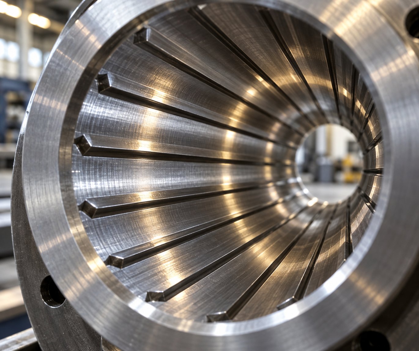
A grooved feed section features a series of longitudinal or helical grooves machined directly into the barrel bore within the feed zone, typically spanning three to four bore diameters in length past the downstream edge of the feed opening. These grooves serve a deceptively simple purpose: they lock PE pellets against the barrel wall, preventing them from rotating with the screw and instead forcing them to move axially forward.
Here's how it works in practice. When PE pellets drop from the hopper into a smooth bore, the only thing preventing them from spinning in place is the friction differential between the barrel wall and the screw surface. Grooves change this equation dramatically. Pellets wedge into the machined channels, creating a mechanical interlock that's far stronger than friction alone. This converts the feed zone from a friction-dependent conveying system into something much closer to positive displacement — what researchers at the University of Stuttgart describe as "nut-screw conveying," where the solid bed moves forward at a rate governed by groove geometry rather than unpredictable friction conditions.
Why does this matter so much for PE specifically? Three reasons. First, polyethylene pellets — whether HDPE, LDPE, or LLDPE — have inherently low friction coefficients compared to polymers like nylon or polycarbonate. That makes PE one of the polymers most prone to feed-zone slippage in smooth-bore systems, particularly at elevated screw speeds. Second, PE lines frequently target high output rates where even small conveying inefficiencies compound into significant throughput losses. Third, PE's relatively low melting point means the feed zone must stay cool to prevent premature softening — and cooler barrel surfaces further reduce the already-low friction available for solids conveying in smooth-bore designs.
The throughput advantages are measurable. Research investigating HDPE solid conveying at high screw speeds found that grooved barrels achieved roughly double the mass throughput of smooth-bore barrels across the tested speed range when processing PE-HD pellets. At screw speeds up to 300 rpm, the relationship between speed and output remained approximately linear for grooved configurations — meaning you got predictably proportional output increases as you turned the screw faster. Industry sources confirm the broader trend: with many polymers, grooved-feed extruders produce 20-40% higher output per rpm than equivalent smooth-bore machines.
Equally important is what happens to output stability at higher screw speeds. The Stuttgart research revealed that both axially grooved and helically grooved barrels converged to similar maximum throughput values above approximately 800 rpm when processing PE-HD, with that maximum ultimately limited by the granule stream the hopper opening could supply — not by friction conditions in the feed zone. In practical terms, this means a properly designed grooved feed section removes the barrel's feed zone as the throughput bottleneck, letting processors push toward the machine's true mechanical and thermal limits.
Perhaps most significant for PE pipe and film producers: grooved feed systems exhibit substantially less sensitivity to downstream back pressure. In the same experimental program, the mass throughput for an entire grooved-feed extruder processing PE showed excellent agreement with results from the isolated feed zone — and increasing die back pressure from 50 bar to 200 bar had essentially no effect on output. Smooth-bore systems, by contrast, showed throughput reductions of 28-48% compared to their isolated feed-zone performance when back pressure was applied. For PE processors running against restrictive dies or screen packs, this pressure independence translates directly into more consistent production.
Grooved Feed vs Smooth-Bore Barrels for PE Applications
Does all of this mean every PE line should run a grooved feed barrel? Not necessarily. Grooved feed technology delivers its strongest advantages in dedicated, high-output PE operations — but it comes with engineering requirements and operational constraints that make it a poor fit for some situations.
Grooved feed sections demand robust, intensive cooling. The grooves work by maintaining mechanical interlock between pellets and the barrel wall, and that mechanism fails if pellets begin to soften and smear into the groove channels. For PE, with its relatively low melting point, this means the grooved section needs aggressive water cooling to keep barrel wall temperatures well below the pellet softening point. The Stuttgart researchers observed that even with intense water cooling, both grooved barrel types led to partial clustering of PE granule particles at certain screw speeds — a phenomenon that can cause operational complications if cooling capacity is insufficient.
Screw design compatibility is another critical factor. A grooved feed section can force substantially more solid material into the downstream barrel than a smooth bore delivers. If the screw's melting section wasn't designed to handle that elevated solids feed rate, you'll face excessive torque, incomplete melting, elevated melt temperature, and unstable production. As industry experience confirms, grooved-feed screws typically require shallower flight channels in the feed section — roughly half the depth used with smooth bores on equivalent-diameter machines — to maintain high forward force in the grooves and adequate compression entering the heated barrel zones.
Feedstock consistency matters more with grooves, too. Pellet geometry — shape, size, and size distribution — directly influences conveying behavior. The Stuttgart study demonstrated that lenticular PE-HD pellets produced 5-13% higher throughput than cylindrical pellets of the same resin, a difference driven primarily by bulk density variation. For PE processors running significant percentages of regrind with inconsistent particle size, smooth-bore barrels are generally more forgiving since their deeper feed channels are less affected by particle size variation.
| Performance Dimension | Smooth-Bore Barrel | Grooved Feed Barrel |
|---|---|---|
| PE Throughput Stability | Moderate; output varies with friction conditions and screw speed | High; near-positive-displacement conveying reduces output variability |
| Back-Pressure Sensitivity | Higher; throughput drops significantly as die or screen-pack resistance increases | Lower; output remains largely independent of downstream pressure changes |
| Feed Zone Cooling Requirement | Standard feed-throat cooling sufficient for most PE grades | Intensive, high-capacity cooling essential to prevent pellet softening in grooves |
| Relative Cost | Lower barrel and system cost; simpler cooling infrastructure | Higher due to groove machining, hardening, and cooling system requirements |
| Best PE Application Fit | Flexible lines processing multiple PE grades, operations using variable regrind content, lower-output applications | Dedicated high-output PE lines: HDPE pipe, HMW-HDPE blown film, PE sheet where consistent throughput and pressure stability are priorities |
One point deserves emphasis: choosing a grooved feed barrel for PE is not a standalone upgrade — it's a system decision. The screw geometry, drive torque capacity, feed-zone cooling infrastructure, and downstream melting section all must be engineered as an integrated package. Swapping a smooth bore for a grooved feed without redesigning the screw is, as experienced processors and machine builders consistently warn, one of the most common and costly mistakes in PE extrusion upgrades.
For dedicated HDPE pipe lines, HMW-HDPE blown film operations, and high-output PE sheet extrusion, a well-engineered grooved feed extruder barrel for PE delivers measurably higher throughput, tighter output stability, and reduced sensitivity to process disturbances — advantages that compound into significant productivity gains over the barrel's service life. For flexible lines processing multiple polymer families, variable regrind streams, or lower-volume PE products, the smooth bore's simplicity and adaptability remain the smarter choice.
Throughput consistency and feed stability solve one half of the PE melt quality equation. But what happens when the resin itself carries contaminants — moisture, volatile residues, trapped air — that no amount of feed optimization can address? That's where barrel venting enters the picture, especially as recycled PE volumes continue to grow.
Barrel Venting Requirements for Recycled PE Extrusion
Recycled PE is no longer a niche feedstock — it's becoming a mainstream requirement driven by circular economy mandates, sustainability commitments, and raw material cost pressures. But here's the uncomfortable reality: the same barrel configuration that runs virgin HDPE or LLDPE beautifully will often produce bubble-riddled, surface-defective, mechanically compromised product the moment you switch to post-consumer recyclate. The difference isn't just the resin. It's what's hiding inside it — and whether your barrel gives those hidden contaminants a way out.
A vented extruder barrel addresses this problem directly, providing controlled escape routes for gases, moisture, and volatile compounds that would otherwise remain trapped in the melt and show up as defects in your finished product. For PE processors expanding into recycled content, understanding when and how to specify barrel venting isn't optional — it's the difference between producing sellable product and generating scrap.
When PE Processing Requires a Vented Barrel
Virgin polyethylene is one of the drier commodity resins available. Its non-hygroscopic nature means it absorbs very little atmospheric moisture, and its relatively simple chemistry produces minimal volatile byproducts during melting. For many virgin PE applications — blown film, pipe, sheet — a standard non-vented screw and barrel configuration handles the job without issue.
Recycled PE tells a very different story. Post-consumer PE arrives at your extruder carrying a cocktail of contaminants that were never part of the original resin. Residual moisture from washing processes, printing ink solvents from labels, adhesive residues from laminated packaging, residual detergents, food residue decomposition products — all of these generate gas during melting. Post-industrial PE regrind, while generally cleaner, can still carry absorbed moisture, processing aid residues, or degradation byproducts from previous thermal histories.
When these volatiles have nowhere to go, they remain dissolved or entrained in the PE melt under the barrel's internal pressure. The moment that melt exits the die and pressure drops, the trapped gases expand — producing bubbles, voids, and pinholes in the extrudate. Even if the bubbles are too small to see with the naked eye, they degrade the mechanical properties of PE pipe, reduce the barrier performance of PE film, and create hazy, rough surface finishes that signal poor quality to your downstream customers.
The consequences extend beyond aesthetics. As devolatilization experts explain, residual volatiles can adversely affect physical properties, physical appearance, stability, and aging performance of the finished article. Residual volatile content alters color, degrades UV stability, and reduces long-term mechanical strength. For PE pipe carrying pressurized fluids or PE film wrapping food products, these aren't cosmetic issues — they're functional failures.
How do you know your PE extrusion line needs a vented barrel? Watch for these indicators:
- Processing post-consumer recyclate: Any PE line regularly running washed post-consumer flake or pelletized PCR should be evaluated for venting, regardless of whether the feedstock has been pre-dried
- Visible surface defects: Pitting, roughness, or "orange peel" texture on extruded PE products that disappears when switching to virgin resin points directly to volatile contamination
- Bubble formation in the melt strand: Bubbles visible in the melt at the die exit or in pelletized output indicate trapped gas that wasn't removed during plasticating
- Off-gassing odors: Noticeable smell at the die or in the finished product — particularly chemical, waxy, or burnt odors — signals volatile compounds being carried through the barrel without extraction
- Declining mechanical test results: Unexplained drops in tensile strength, impact resistance, or elongation at break when processing recycled PE blends suggest void formation weakening the polymer matrix
Vented Barrel Design Considerations for Recycled PE
A vented extrusion screw barrel isn't simply a standard barrel with a hole drilled in it. Effective devolatilization requires an integrated design approach that coordinates vent port location, melt decompression geometry, sealing elements, and vacuum infrastructure to extract volatiles without disrupting the extrusion process.
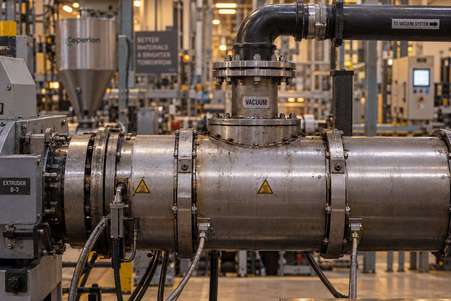
In a typical vented barrel for PE, one or two vent ports are positioned downstream of the first-stage metering zone. At this point, the PE melt has been fully plasticized and homogenized under pressure. The screw geometry then transitions into a decompression section — a zone where channel depth increases abruptly, dropping melt pressure and allowing dissolved volatiles to flash out of solution. The vent port, located in the barrel wall above this decompressed zone, provides the escape pathway for the released gases.
Vent port sizing matters more than many processors realize. Too small an opening restricts vapor flow, limiting devolatilization efficiency and potentially causing pressure buildup beneath the vent. Too large an opening risks melt creeping up into the port, especially during process upsets or throughput changes. Industry experience shows that vent blockage by polymer flowing into the opening is one of the most common operational problems with vented systems — requiring manual clearing or even line shutdown when it occurs.
Atmospheric versus vacuum venting represents a key design choice. Atmospheric vents — simple open ports — work for removing large volumes of steam or entrained air, particularly in the early stages of processing heavily moisture-laden recycled PE. Vacuum venting, where a pump draws the vent port down to pressures typically in the range of 20-27 inches of mercury, provides the additional driving force needed to extract low-concentration volatiles and achieve the lowest possible residual levels. As process engineers note, a good rule of thumb is that each vent stage can reduce volatile concentration by roughly an order of magnitude — meaning a single vacuum vent might take residuals from percent-level down to tenths of a percent, while a second vent stage pushes them lower still.
Melt seal design is arguably the most critical — and most underappreciated — element in a vented barrel system. The melt seal is a filled section of the screw upstream of each vent port that prevents vacuum from pulling air backward through the barrel from the feed zone, and a downstream seal that prevents melt from backing up into the vent opening. If the upstream seal fails, vacuum draws air through the barrel rather than extracting volatiles from the melt. If the downstream seal is too restrictive or the filled length reaches the vent port — due to increased die pressure, screen fouling, or screw wear — melt floods the vent and devolatilization stops entirely. For PE, where many recycling lines operate at high throughput with variable feedstock quality, robust melt seal design provides the operational stability that keeps venting functional shift after shift.
Barrel bore tolerances in the vent zone also affect performance. The decompression section operates with partially filled screw channels, meaning the melt forms thin films on the barrel wall and screw surfaces. These thin films are where devolatilization actually happens — volatiles escape only at the melt-gas interface, and the thinner the film, the shorter the diffusion path for trapped molecules to reach that interface. Tight bore tolerances in the vent zone ensure consistent film thickness distribution, which directly impacts how efficiently volatiles are stripped from the PE melt.
The growing emphasis on PE recycling and circular economy initiatives is accelerating demand for vented barrel configurations across the industry. Equipment manufacturers report that recycled plastics are driving significant increases in extruder sales, with machines requiring additional venting capability — sometimes two or three vent stages — to handle the elevated moisture and contamination levels inherent in post-consumer PE streams. For single-screw PE lines, this typically means specifying a two-stage screw and barrel with at least one vacuum vent port, while processors handling the most contaminated feedstocks may need to consider tandem extrusion setups or pre-compounding with devolatilization before final product extrusion.
Venting handles what's inside the resin. But the barrel's ability to deliver consistent output quality also depends on something more fundamental — the physical dimensions of the bore itself and how precisely those dimensions are maintained across the full barrel length.
Barrel Bore Sizing and Alignment for PE Output Quality
Every barrel specification discussed so far — liner material, thermal zones, feed section type, venting — performs its function within a cylindrical bore of a specific diameter. That diameter isn't arbitrary. The extruder barrel bore diameter is the single most influential dimensional parameter for determining how much PE your line can produce, and its precision directly governs whether that output meets your quality standards or quietly undermines them.
Yet bore sizing and dimensional integrity rarely receive the same attention as material selection or thermal configuration. For PE processors, that's a costly oversight. Polyethylene's sensitivity to shear variation, its relatively low melt viscosity compared to engineering polymers, and the tight dimensional tolerances demanded by PE end products — pipe wall thickness, film gauge, wire coating concentricity — all amplify the consequences of getting bore dimensions wrong or letting them drift over time.
Matching Barrel Bore Diameter to PE Application Throughput
Think of the barrel bore as the engine displacement of your extrusion line. A larger bore accommodates a larger-diameter screw, which sweeps a greater channel volume per revolution. Combine that with screw speed, and you define the volumetric conveying capacity of the system. As extrusion engineering references confirm, a larger screw diameter generally provides a larger conveying volume — and output scales with that volume multiplied by rotational speed and melt density.
What makes bore sizing a PE-specific challenge is the sheer range of throughput demands across polyethylene applications. A wire coating line running LDPE might use a barrel bore in the 30-60 mm range, producing modest output at moderate screw speeds where melt temperature control and coating concentricity take priority over raw throughput. A high-output HDPE pipe extrusion line, by contrast, might require bore diameters exceeding 150 mm to achieve the hundreds-of-kilograms-per-hour output rates needed for large-diameter pipe production. PE blown film lines fall somewhere in between, balancing throughput with the melt homogeneity demands that determine film optical quality.
Bore diameter doesn't act in isolation — it interacts with screw speed and PE melt viscosity to determine what's actually achievable. A larger bore at lower screw speed may deliver the same output as a smaller bore running faster, but the shear history imposed on the PE melt differs significantly between those two scenarios. PE grades, particularly HDPE, are sensitive to excessive shear — high screw speeds in undersized bores generate more viscous heating, elevate melt temperature beyond the target window, and degrade the very properties you're trying to preserve. Conversely, an oversized bore running at unnecessarily low screw speeds may not generate enough shear to fully homogenize the melt, resulting in temperature gradients and inconsistent product properties.
The practical takeaway: bore diameter selection for PE must balance three factors simultaneously — the target throughput for your application, the screw speed range your drive system can deliver, and the shear sensitivity of the specific PE grade being processed. Specifying bore diameter based on throughput alone, without considering how that diameter interacts with PE rheology, leads to lines that hit their output target but miss their quality target.
Barrel Alignment and Concentricity for PE Product Uniformity
Imagine a perfectly specified barrel — right diameter, right liner, right thermal zones — installed with its centerline offset from the gearbox thrust shaft by even a fraction of a millimeter. What happens? The plastic extruder screw no longer sits concentrically within the bore. One side of the screw flight rides closer to the barrel wall while the opposite side opens up additional clearance. PE melt flowing through the tighter gap experiences higher shear and generates more viscous heat. Melt flowing through the wider gap sees less shear and runs cooler. The result is a circumferentially uneven melt temperature — and for PE, that unevenness translates directly into product defects.
In PE pipe, barrel-to-screw misalignment shows up as wall thickness variation around the pipe circumference — a defect that can cause pressure rating failures. In blown film, it produces gauge bands that create weak spots and processing instability at the winding stage. In wire coating, concentricity errors mean uneven insulation thickness that fails electrical testing. These aren't hypothetical problems. As alignment specialists document, misalignment between the barrel and gearbox thrust shaft leads to premature barrel and screw wear, decreased throughput, poor mixing, uneven melt temperatures, and surging — a list of symptoms that PE processors frequently troubleshoot as process issues when the root cause is actually mechanical.
Misalignment also accelerates wear asymmetrically. The screw flight contacts the barrel wall preferentially on one side, grinding through the liner material in a localized pattern rather than wearing evenly around the circumference. Over time, this creates an oval-shaped bore — further worsening concentricity, increasing leakage flow past the screw flights, and compounding the melt quality problems. For extruder screws and barrels running PE at high output rates over extended campaigns, this progressive asymmetric wear can cut barrel service life significantly compared to a properly aligned system.
Proper alignment isn't a one-time event. Thermal growth during operation, foundation settling, mechanical shock from maintenance activities, and barrel replacements can all introduce or reintroduce misalignment. Industry best practice calls for regular alignment inspections using optical or laser-based measurement systems, along with bore gauging to monitor wear profiles and straightness checks using 3D metrology tools such as laser trackers. Thermal growth studies — where measurements are taken in both cold and hot conditions — are especially relevant for PE lines that run continuously, since barrel displacement under operating temperature can differ meaningfully from cold-install alignment.
Here is the checklist of barrel dimensional parameters that PE processors should verify during installation, after maintenance, and at regular inspection intervals:
- Bore diameter tolerance: Confirm that the bore diameter falls within the manufacturer's specified tolerance band across the full barrel length — not just at the ends. Localized wear or manufacturing variation mid-barrel directly increases leakage flow and reduces PE melt consistency.
- Straightness over full length: Measure the barrel's axial straightness using precision optical or laser-based instruments. Any curvature or deviation creates uneven screw-to-barrel clearance, causing the same asymmetric shear and wear problems as offset misalignment.
- Concentricity at flange connections: Verify that the barrel bore centerline is concentric with the mounting flanges at both the gearbox and die end. Flange misalignment is one of the most common — and most correctable — sources of barrel-to-screw offset.
- Surface finish of the bore: Inspect the internal bore surface for scoring, roughness changes, or localized damage. For PE, bore surface condition affects both friction characteristics in the feed zone and melt flow behavior in the metering zone. Degraded surface finish can alter solids conveying, increase shear heating, and introduce contamination into the melt stream.
These dimensional checks aren't just quality assurance formalities — they're diagnostic tools. A bore gauge profile that shows accelerated wear in specific zones tells you exactly where your barrel is failing and why your PE product quality is drifting. A straightness measurement that reveals thermal distortion identifies whether your barrel supports or mounting arrangement need correction.
Bore sizing determines capacity. Alignment determines quality. Together, they establish the physical foundation on which every other barrel specification performs — or fails. With these fundamentals in place, the next question becomes practical: which specific barrel configuration does your PE application actually need?
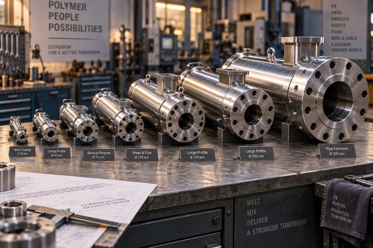
PE Application Matrix and Recommended Barrel Configurations
Every PE end product places a different set of demands on the barrel — yet most processors spec their equipment based on general-purpose guidelines that treat blown film, pipe, and recycling lines as if they need the same hardware. They don't. An extruder barrel for blown film faces fundamentally different thermal, mechanical, and throughput challenges than a PE pipe extrusion barrel running large-diameter HDPE profiles at maximum output. Matching barrel configuration to your specific application is what separates lines that consistently hit targets from lines that fight quality issues shift after shift.
Let's break down the recommended barrel specifications for each major PE product category — then pull it all together into a single reference matrix you can use during your next equipment specification or replacement decision.
Barrel Configurations for PE Film and Sheet Extrusion
Blown film lines running LDPE and LLDPE are among the most demanding PE applications when it comes to melt homogeneity. Even minor temperature variations or unmelt particles translate directly into optical defects — haze, gels, and gauge bands that your downstream customers will notice immediately. This is why an extruder barrel for blown film typically requires longer L/D ratios in the 28:1 to 33:1 range, providing the residence time and working length needed to fully homogenize the melt before it reaches the die.
For high-output blown film operations — particularly those running HMW-HDPE or metallocene LLDPE at competitive line speeds — grooved feed sections deliver the throughput stability and back-pressure independence that keep output consistent across long production campaigns. When recycled PE blends enter the picture, bimetallic liners become essential to protect against the accelerated wear that contaminants introduce.
Cast film extrusion shares many of these requirements but often runs at even higher throughput rates, favoring slightly larger bore diameters for increased volumetric capacity. Melt temperature uniformity remains critical since cast film quality depends on consistent drawdown behavior at the chill roll.
Sheet extrusion pushes throughput demands further still. Wider dies and thicker gauges require substantially higher output, which typically means larger-diameter single screw barrel configurations with robust bimetallic liners to handle the sustained mechanical stress of high-volume production. Sheet lines processing recycled PE blends benefit from vented barrel designs to remove volatiles that would otherwise cause surface defects or internal voids.
Barrel Specifications for PE Pipe and Blow Molding
HDPE pipe extrusion is arguably the most structurally demanding PE application for barrel engineering. Large-diameter pipe requires large-bore barrels pushing significant output — often hundreds of kilograms per hour — over production runs that can span weeks or months without interruption. The PE pipe extrusion barrel must deliver tight bore-to-screw concentricity for uniform wall thickness, high-wear-resistance liners (typically iron-boron or tungsten carbide bimetallic) to survive extended campaigns, and precisely controlled thermal zones to maintain the consistent melt temperature that determines pipe pressure rating.
Grooved feed sections are standard in dedicated HDPE pipe lines, where their throughput stability and pressure independence provide the process consistency that pipe quality standards demand. Venting is generally unnecessary for virgin HDPE pipe production but becomes important when recycled PE content is incorporated into the formulation.
Blow molding presents a different challenge. Parison consistency — the uniformity of the molten tube that forms the bottle or container — depends heavily on melt temperature control. Barrel configurations for PE blow molding favor moderate L/D ratios with tight zone-by-zone thermal management. Since blow molding lines frequently process HDPE at relatively high melt viscosity, the barrel must provide enough shear for complete melting without overheating the polymer and reducing parison melt strength.
Wire and cable coating, while a smaller-volume PE application, requires exceptional concentricity and melt temperature uniformity. The barrel bore is typically smaller in diameter, and smooth-bore feed sections are common since throughput demands are moderate. Coating thickness uniformity — often measured in fractions of a millimeter — makes barrel alignment and bore tolerance critical quality levers.
The table below consolidates these application-specific recommendations into a single reference matrix:
| PE Application | Recommended L/D Range | Feed Section Type | Preferred Liner Material | Venting Need |
|---|---|---|---|---|
| Blown Film (LDPE/LLDPE) | 28:1 to 33:1 | Grooved (high-output) / Smooth (standard) | Bimetallic iron-boron or nitrided (virgin PE) | No (virgin) / Yes (recycled blends) |
| Cast Film | 28:1 to 33:1 | Grooved preferred for throughput stability | Bimetallic iron-boron | No (virgin) / Yes (recycled blends) |
| Pipe (HDPE) | 24:1 to 30:1 | Grooved (standard for dedicated lines) | Bimetallic iron-boron or tungsten carbide | No (virgin) / Yes (recycled content) |
| Blow Molding (HDPE) | 24:1 to 28:1 | Smooth or grooved depending on output target | Bimetallic iron-boron | Generally No |
| Wire & Cable Coating | 24:1 to 28:1 | Smooth | Nitrided steel (virgin PE) or bimetallic | No |
| Sheet Extrusion | 28:1 to 33:1 | Grooved preferred for high output | Bimetallic iron-boron or nickel-chromium (recycled PE) | No (virgin) / Yes (recycled blends) |
| Pelletizing / Recycling | 30:1 to 36:1 | Smooth (variable feedstock) or grooved (consistent feed) | Nickel-chromium bimetallic (corrosion + abrasion) | Yes (typically one or two vacuum vent stages) |
A few patterns emerge from this matrix. Grooved feed sections appear wherever throughput consistency and back-pressure independence matter most — pipe, film, and sheet. Bimetallic liners dominate across nearly all PE applications, with nitrided steel appropriate only for lower-output virgin PE processing. And venting requirements track almost perfectly with recycled PE content, reinforcing the point that recycling isn't just a feedstock decision — it's a barrel design decision.
Sourcing barrel configurations that match these application-specific requirements means working with suppliers who engineer for PE across the full product range rather than offering generic solutions. Suppliers like NANHAIYA offer custom and replacement single screw barrel configurations spanning pipe, film, sheet, pelletizing, and recycling applications — with engineering tailored to each product category's unique demands for liner material, feed section type, bore sizing, and venting. That kind of application-specific capability matters because, as this matrix illustrates, a barrel optimized for blown film would be a poor fit for a recycling line, and vice versa.
Having the right barrel configuration for your PE application is only half the equation, though. The other half is knowing exactly how to communicate those specifications to your supplier — and how to evaluate whether they can actually deliver what your line needs.
How to Select and Source the Right Barrel for PE Lines
You've identified the right liner material, decided between grooved and smooth-bore feed sections, confirmed your venting requirements, and mapped your application against the barrel configuration matrix. All that engineering knowledge is valuable — but it only translates into real performance gains when you can communicate those specifications precisely to a barrel supplier and verify that the supplier can actually deliver what your PE line demands.
This is where many procurement decisions fall apart. A plant engineer who understands exactly what the barrel needs to do may hand off a vague purchase order that reads "replacement barrel for 90 mm PE extruder" — and receive a generic component that misses half the application-specific requirements. On the supplier side, a manufacturer without PE extrusion experience may produce a dimensionally correct barrel that fails to account for the thermal management, liner chemistry, or bore tolerance demands unique to polyethylene processing.
Bridging that gap requires two things: knowing what to specify and knowing how to evaluate who builds it.
Key Specification Criteria When Ordering a PE Extruder Barrel
Every replacement extruder barrel order should start with a complete specification package. Sounds obvious, yet experienced manufacturers consistently report that incomplete technical information is the single most common cause of mismatched components arriving at the plant. For PE specifically, the specification must go beyond standard dimensions to capture the processing conditions that drive barrel engineering decisions.
Here's the information your extruder barrel supplier needs — listed in the order that narrows the design space most efficiently:
- PE grade(s) to be processed: Specify the exact resin type — HDPE, LDPE, LLDPE, mLLDPE, or HMW-HDPE — along with melt flow index ranges. Different PE grades impose different thermal, shear, and wear demands on the barrel, and a supplier can't optimize the design without this information.
- Filler content and recycled material percentage: If you're running calcium carbonate, glass fiber, color masterbatch, or any percentage of post-consumer or post-industrial recyclate, state it explicitly. This drives liner material selection more than any other single variable.
- Target throughput: Define your required output in kg/hr, including both typical operating rates and peak demands. Throughput targets interact with bore diameter and screw speed to determine whether the barrel's thermal and mechanical capacity matches your production goals.
- Existing screw geometry compatibility: Provide the screw design details — compression ratio, flight geometry, barrier or mixing section locations — or at minimum the screw manufacturer and model. The barrel must be engineered to work with the specific screw and barrel combination, not just fit dimensionally.
- Liner material requirement: Based on your PE grade and filler analysis, specify whether you need nitrided steel, iron-boron bimetallic, nickel-chromium bimetallic, or tungsten carbide liner — or ask the supplier for a recommendation backed by their experience with similar PE applications.
- Venting needs: State whether the barrel requires vent ports, how many, and whether atmospheric or vacuum venting is needed. For recycled PE applications, this is non-negotiable information.
- Feed section type: Specify grooved or smooth-bore feed, including groove geometry details if applicable. If you're unsure, describe your throughput stability requirements and back-pressure conditions so the supplier can recommend the right approach.
- Dimensional tolerances: Define bore diameter tolerance, straightness requirements, flange concentricity, and bore surface finish specifications. If your OEM documentation includes these values, provide them. If not, discuss tolerance requirements with the supplier based on your product quality demands.
Why does communicating the specific PE application matter so much? Because, as the configuration matrix in the previous section demonstrates, a barrel optimized for HDPE pipe extrusion looks fundamentally different from one designed for LDPE blown film or PE recycling pelletizing. A supplier who only receives dimensional data — bore diameter, overall length, flange specifications — can produce a barrel that bolts onto your machine but misses the thermal zone layout, liner chemistry, and feed section design that your application actually requires. The more context you provide about the end product, the better the barrel you'll receive.
One practical tip: if original manufacturing drawings are unavailable for a replacement order, detailed measurements, photographs of the existing barrel (including wear patterns), and information about your machine model, motor power, and gearbox ratio give a capable supplier enough to reverse-engineer an appropriate replacement — and often to improve on the original design if it wasn't optimized for PE in the first place.
Evaluating Barrel Suppliers for PE Extrusion Lines
Not every screw and barrel manufacturer has the experience or engineering depth to deliver a barrel that performs well in PE service. The plastics machinery component market is broad — industry analysis indicates the global feed screw and barrel market reached $1.86 billion in 2025, with continued growth driven by bimetallic adoption and increasingly demanding processing conditions. That scale means you'll find hundreds of suppliers quoting against your specifications. Sorting credible PE-capable manufacturers from commodity parts traders requires evaluating capabilities that go beyond price and lead time.
Here's what to look for when qualifying a supplier for screw and barrel for PE extrusion applications:
- PE application experience: Ask specifically about PE projects the supplier has completed. A manufacturer who has built barrels for HDPE pipe, PE blown film, and PE recycling lines understands the grade-specific requirements that a general-purpose supplier may overlook. Request reference applications or case examples.
- Custom engineering capability: PE barrel optimization requires design flexibility — adjusting feed zone geometry, specifying liner alloy chemistry, configuring vent port locations, and matching thermal zone layouts to your process. Suppliers with in-house engineering teams can adapt designs to your exact requirements rather than offering only catalog dimensions. As supplier evaluation frameworks emphasize, a manufacturer without dedicated engineering staff can only reproduce buyer-supplied drawings — a significant limitation when you need a solution tailored to a specific PE grade or process condition.
- Material certifications and process documentation: Request EN 10204 3.1 material certificates for base steel and liner alloys, hardness test reports at multiple bore locations, and metallographic cross-sections for bimetallic liners. These documents verify that every delivered barrel meets the same metallurgical standard as the approved specification — not just the dimensional prints.
- Dimensional inspection reports: A credible supplier provides CMM (coordinate measuring machine) data or equivalent inspection records documenting bore diameter, straightness, concentricity, and surface finish for every barrel shipped. For PE applications where bore tolerance directly affects melt uniformity and product quality, these reports aren't optional — they're your quality assurance baseline.
- Ability to supply replacement barrels matching OEM specifications: If you're replacing a worn barrel on an existing PE line, the supplier must be able to replicate or improve upon the original manufacturer's specifications — including mounting dimensions, heating band fitment, thermocouple port locations, and cooling channel connections. A barrel that doesn't interface cleanly with your existing extruder components creates installation headaches and potential alignment problems.
- Range of PE application coverage: Suppliers who serve multiple PE end markets — film, pipe, sheet, pelletizing, recycling — demonstrate breadth of understanding that single-application manufacturers may lack. When your production mix evolves or you add new PE lines, a supplier with broad application coverage simplifies procurement and ensures consistent quality across your equipment fleet.
- Responsiveness and technical support: Evaluate how the supplier responds to technical questions during the quotation process. A manufacturer who asks detailed questions about your PE grade, throughput, and application before quoting is demonstrating the engineering engagement that produces well-matched barrels. A supplier who quotes immediately from dimensional data alone may deliver a barrel that fits but doesn't perform.
Qualifying a new supplier doesn't require betting your entire production on an unproven partner. Start with a single replacement barrel for a non-critical line or a secondary extruder. Run it through a full production campaign, monitor wear progression, document melt quality metrics, and compare performance against your existing barrel's track record. That real-world validation is worth more than any catalog specification or sales presentation.
For PE processors evaluating sourcing options across the full range of applications covered in this article, NANHAIYA's single screw barrel product line is worth considering. The company provides custom and replacement single screw barrels engineered for pipe, film, sheet, pelletizing, recycling, and general-purpose PE extrusion lines — covering the breadth of applications where PE-specific barrel engineering makes a measurable difference. Their product page serves as a useful starting point for PE processors comparing supplier capabilities against the specification and evaluation criteria outlined above.
The right extruder barrel for PE isn't the cheapest option on the quote sheet — it's the one that delivers the lowest cost per kilogram of quality product over its full service life.
Barrel selection for polyethylene processing is ultimately an engineering decision with procurement consequences, not a procurement decision with engineering afterthoughts. Every topic covered in this guide — melt behavior, liner materials, thermal management, grooved feed technology, venting, bore sizing, alignment, and application-specific configuration — feeds into a single outcome: whether your PE line produces consistent, high-quality product at target throughput, or whether it fights you on every run because the barrel wasn't built for what you're actually asking it to do. Define your specifications completely, evaluate suppliers rigorously, and treat the barrel as the precision-engineered PE processing component it is — not as a commodity steel tube. Your melt quality, your product quality, and your bottom line all depend on it.
Frequently Asked Questions About Extruder Barrels for PE
1. What makes an extruder barrel for PE different from a standard barrel?
PE's semi-crystalline molecular structure, narrow melt temperature window, and high abrasion potential — especially with filled or recycled grades — require barrel engineering that generic thermoplastic barrels cannot deliver. HDPE's sharp crystalline melting point demands concentrated thermal input in the transition zone, while LDPE and LLDPE need a more gradual heating profile. PE also benefits from longer L/D ratios (24:1 to 33:1) to ensure complete crystallite melting and melt homogenization. These grade-specific thermal, mechanical, and geometric demands mean a barrel built for general-purpose extrusion will often cause surging, gel formation, or poor surface finish when processing polyethylene.
2. Should I use a grooved feed or smooth-bore barrel for PE extrusion?
The choice depends on your application and throughput goals. Grooved feed barrels mechanically lock PE pellets against the barrel wall, delivering near-positive-displacement conveying that can roughly double mass throughput compared to smooth-bore designs. They also resist back-pressure-related output drops, making them ideal for dedicated high-output HDPE pipe, HMW-HDPE blown film, and PE sheet lines. However, grooved feed sections require intensive water cooling, compatible screw geometry with shallower feed channels, and consistent pellet size. Smooth-bore barrels remain the better fit for flexible lines processing multiple PE grades, operations using variable regrind content, or lower-volume applications where simplicity is valued.
3. When does recycled PE processing require a vented extruder barrel?
A vented barrel becomes necessary whenever your PE feedstock carries moisture, volatile residues, or contaminants that generate gas during melting. Post-consumer recyclate commonly contains residual wash water, printing ink solvents, adhesive residues, and decomposition byproducts that produce bubbles, surface defects, and reduced mechanical properties if not extracted. Key indicators include visible pitting or rough texture on extruded products, bubble formation in the melt strand, off-gassing odors at the die, and declining tensile or impact test results. Vented barrels use decompression zones and one or two vent ports — atmospheric or vacuum — to strip these volatiles from the melt before it exits the die.
4. Which barrel liner material is best for PE extrusion?
The best liner depends on your PE grade and processing conditions. Gas-nitrided steel (such as Nitralloy 135M) works well for virgin PE without fillers at moderate output rates, offering the lowest cost but limited wear depth. Iron-boron bimetallic liners suit PE compounds with up to roughly 30% mineral fillers or high-output virgin PE lines. Nickel-chromium bimetallic alloys add corrosion resistance for recycled PE that produces acidic off-gassing during melting. Tungsten carbide liners deliver the highest abrasion resistance for heavily filled or glass-fiber-reinforced PE but at a premium price. Suppliers like NANHAIYA offer custom single screw barrels with application-matched liner materials across pipe, film, sheet, and recycling lines at nhyscrews.com.
5. How does barrel bore alignment affect PE product quality?
Even minor barrel-to-screw misalignment creates uneven clearance around the bore circumference, causing one side of the melt stream to experience higher shear and more viscous heating than the other. For PE, this translates into wall thickness variation in pipe, gauge bands in blown film, and uneven insulation thickness in wire coating. Misalignment also accelerates asymmetric wear, gradually creating an oval-shaped bore that compounds quality problems over time. Best practice calls for verifying bore diameter tolerance across the full barrel length, checking straightness with laser-based instruments, confirming flange concentricity at both ends, and inspecting bore surface finish — both during installation and at regular maintenance intervals.
Written by
Nanhaiya Technical Team
Zhoushan Nanhaiya Plastic Machinery Co., Ltd.
The Nanhaiya technical team supports screw and barrel manufacturing projects through application review, technical communication, custom manufacturing coordination, and production and quality control.
Discuss Your Application
Related Articles
More insights on screw barrel technology and plastics processing.

What Nobody Tells You About Screw Barrel For Plastic Machine Design
Oct 10, 2026
Learn how screw barrel for plastic machine design affects melt quality, throughput, and wear life. Covers geometry, resin matching, troubleshooting, and sourcing.
Read Article
Single Screw Extruder for Sheet: Stop Guessing, Start Specifying
Oct 9, 2026
Learn how to specify a single screw extruder for sheet production. Covers screw geometry, resin-specific processing, troubleshooting, and maintenance best practices.
Read Article
PE Pipe Extruder Machine: What Datasheets Won't Tell You
Oct 9, 2026
Learn how a PE pipe extruder machine works, key specs explained, material grade selection, maintenance tips, and buyer guidance beyond the datasheet.
Read ArticleLooking for something else?
Search by material, symptom or product and jump straight to the relevant page.
These are navigation suggestions based on keyword matching — not a quotation, not a delivery commitment, and not a substitute for engineering review. Final specification is confirmed by our engineers against your drawings and processed material.
Need help with screw barrel selection?
Share your machine model, processed material and application. Our team can help with pricing and technical support.