

Understanding Extruder Barrel Alignment and Its Critical Role
Imagine your extruder running smoothly one quarter, then quietly drifting out of spec the next — consuming more energy, chewing through screws faster, and producing inconsistent product. The culprit is often invisible to the naked eye: barrel misalignment measured in thousandths of an inch. For maintenance managers and plant engineers tasked with protecting multi-million-dollar extrusion assets, understanding what is extruder barrel alignment — and why it matters — is the first step toward eliminating one of the most overlooked sources of preventable downtime.
What Is Extruder Barrel Alignment and Why Does It Matter
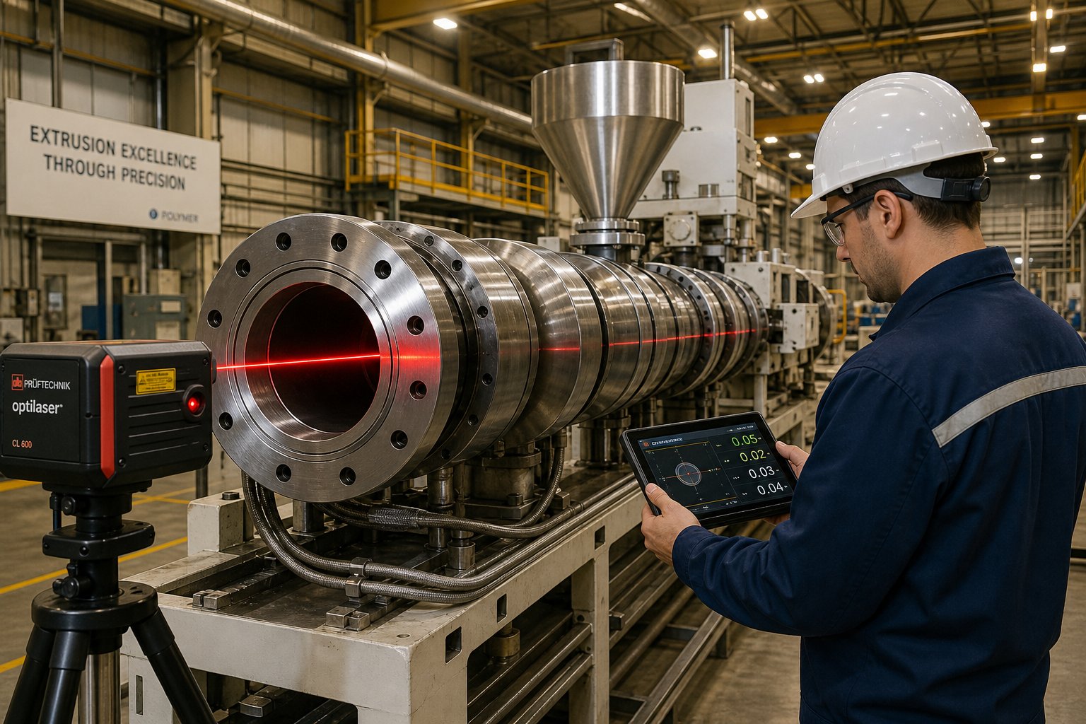
Extruder barrel alignment is the process of verifying and correcting the coaxial relationship between the extruder barrel bore, gearbox output shaft (drive quill), and drive motor to ensure the screw rotates concentrically within the barrel without deflection or uneven contact.
That definition captures the core idea, but the real-world implications run much deeper. When a barrel bore centerline drifts even slightly from the gearbox axis of rotation, the screw is forced into asymmetric contact with the barrel wall. This creates localized metal-to-metal wear, increases radial loads on the gearbox, and drives up motor amperage. As Plastics Technology reports, processors who maintain proper alignment have seen barrel and screw life increase by two to three times compared to misaligned systems. In extreme cases, misalignment leads to catastrophic failure — screws that break outright or form adhesive welds with the barrel, seizing the extruder entirely.
A common misconception is that alignment can be checked with a simple level. Not so. Leveling only measures the outside surface of the barrel in the vertical plane, which has virtually nothing to do with the bore centerline's relationship to the drive quill's rotation axis. Professional alignment requires optical or laser instrumentation positioned inside the gearbox and barrel to measure the actual coaxial deviation.
How Misalignment Develops in Plastics Extrusion Equipment
So if an extruder was aligned at the factory, why does it drift? The causes of extruder barrel misalignment are progressive and often interconnected.
Thermal expansion differentials are a primary driver. Steel expands at approximately 0.000006 in./in./°F, meaning a 4.5-inch, 36:1 barrel operating at a uniform 450°F grows roughly 0.320 inches longer than its room-temperature length. If barrel supports restrict this expansion or force it off-axis, the barrel bends rather than grows straight. Burned-out heater bands, half-heaters around a vent section, or unbalanced heating zones compound the problem by creating uneven thermal growth along the barrel length.
Barrel support degradation is equally damaging. Support joints made from corrosive materials can seize over time, locking the barrel in place and preventing free sliding during heat-up. Supports that lack sufficient rigidity may tip or shift under the barrel's weight as thermal expansion pushes against them.
Foundation and base-frame settling affects larger extruders most severely. For machines above 3.5 inches (90 mm), the bases are rarely rigid enough to hold the manufacturer's original alignment indefinitely. Concrete foundation creep, vibration-induced settling, and even nearby construction activity can introduce angular or offset deviations that worsen with every thermal cycle.
Improper reassembly after maintenance rounds out the list. Every time a barrel is removed for relining, replacement, or system repair, it must be realigned to the gearbox drive quill upon reinstallation. Skipping this step — or relying on visual methods rather than instrumented measurement — virtually guarantees some degree of misalignment from day one.
The insidious nature of barrel misalignment is that it rarely announces itself with a single dramatic failure. Instead, it manifests as a slow escalation of wear rates, energy costs, and quality drift that gets attributed to other causes. By the time someone suspects alignment, the damage to barrels, screws, and gearbox components may already be significant. Recognizing the specific warning signs — before they escalate into unplanned shutdowns — is where a structured diagnostic approach becomes invaluable.
Warning Signs Your Extruder Needs Professional Alignment
A structured diagnostic approach starts with knowing exactly what to look for. The symptoms of extruder barrel misalignment rarely appear in isolation — they accumulate gradually, disguised as routine wear or process variability. Maintenance teams that can identify these red flags early gain a critical advantage: they can schedule corrective alignment before the damage compounds into emergency barrel replacements or extended production shutdowns.
Mechanical and Operational Symptoms of Barrel Misalignment
When the barrel bore centerline deviates from the gearbox output shaft axis, the screw is physically forced into one side of the barrel. That asymmetric contact triggers a cascade of mechanical consequences you'll notice across multiple systems simultaneously.
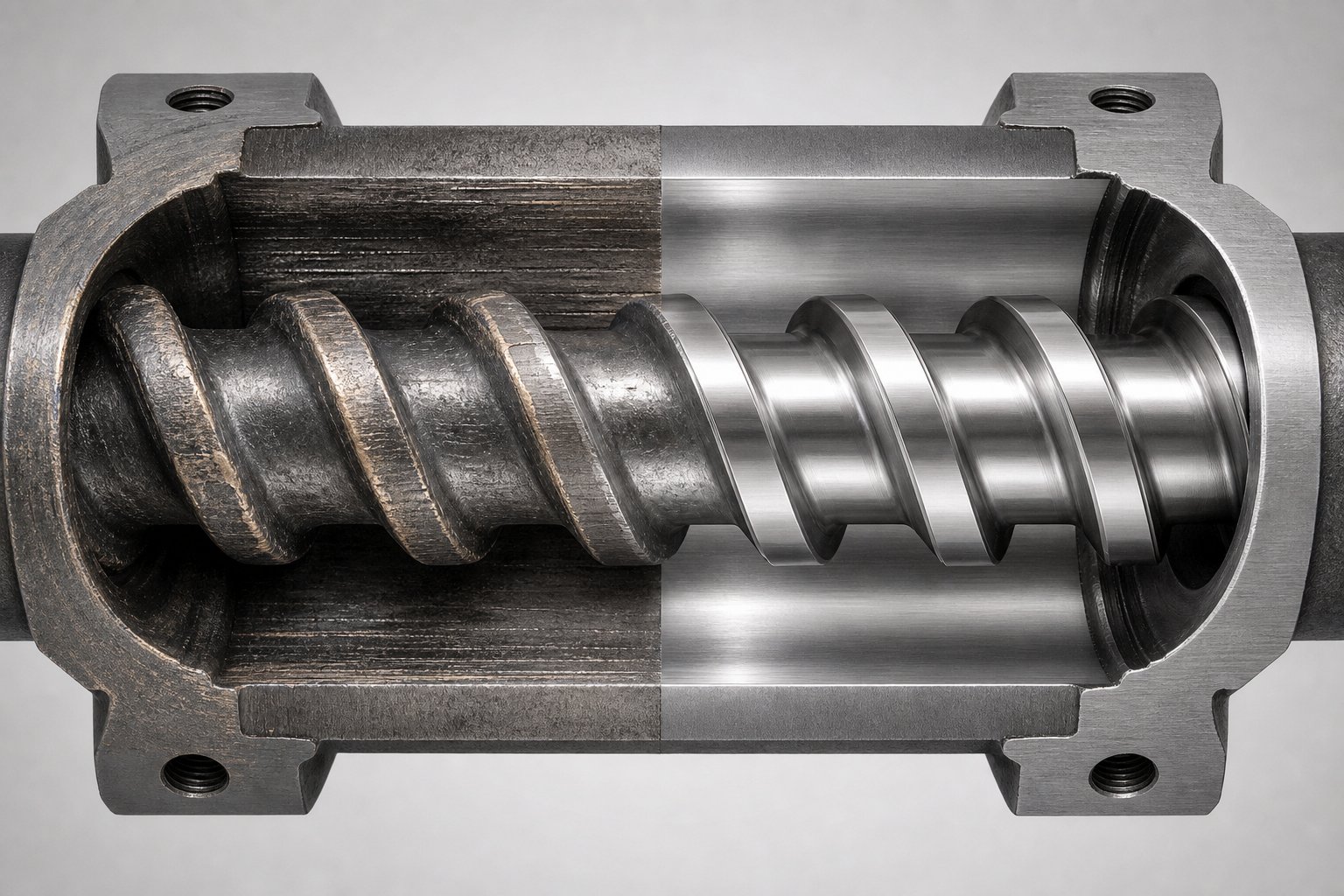
Accelerated and uneven wear patterns are the most telling clue. A properly aligned barrel wears uniformly around its circumference. Misalignment creates a characteristic one-sided wear pattern — heavier on one side of the barrel bore and the corresponding screw flight tips. As Plastics Technology notes, barrel alignment problems are one of the primary mechanisms driving screw wear, alongside abrasive fillers and solids wedging. If you're pulling screws and consistently finding wear concentrated on one side, misalignment is a strong suspect.
Increased motor amperage draw follows logically. A screw dragging against the barrel wall encounters greater frictional resistance, and the drive motor responds by pulling more current. According to predictive maintenance data from extrusion monitoring systems, motor amps exceeding baseline by more than 10% at rated screw speed often signal that something is mechanically restricting the screw — and misalignment is a leading cause.
Abnormal vibration at the gearbox-barrel connection is another hallmark. When the rotational axis of the screw doesn't match the gearbox thrust shaft, the resulting angular or offset misalignment generates cyclic radial forces. You'll feel or measure this as extruder vibration caused by misalignment concentrated at the feed throat area, the gearbox housing, or the barrel flange connection. Left unchecked, these radial loads accelerate thrust bearing degradation and can lead to premature thrust bearing failure — one of the most expensive gearbox repairs in extrusion.
Difficulty maintaining melt temperature uniformity is a subtler symptom that often gets blamed on heater bands or thermocouples. Misalignment changes the annular gap between screw and barrel, altering heat transfer and shear heating patterns along the barrel length. The result is zone-to-zone temperature inconsistencies that resist normal PID tuning.
Product Quality Indicators That Point to Alignment Problems
Mechanical symptoms stay inside the machine. Quality problems, on the other hand, show up in your product — and your scrap bin. How to tell if an extruder barrel is misaligned often starts with what's happening downstream rather than at the extruder itself.
Inconsistent melt pressure is a primary quality indicator. A misaligned screw creates uneven channel depths and irregular melt conveyance, producing pressure fluctuations at the barrel discharge. These fluctuations manifest as surging — rhythmic variations in output rate that cause gauge variation in film, wall thickness swings in pipe, and dimensional inconsistencies in profiles.
Poor melt homogeneity compounds the problem. Uneven screw-to-barrel clearance means some material receives excessive shear while other material passes through with insufficient mixing. The result is a melt stream with inconsistent temperature and viscosity, which degrades product appearance, mechanical properties, and dimensional stability.
These quality issues drive up scrap rates, trigger customer complaints, and can force operators to reduce line speeds — cutting throughput to maintain barely acceptable product quality. OASIS Alignment Services identifies decreased throughput, back-flighting, poor mixing, and uneven melt temperatures among the direct consequences of misalignment, all of which feed directly into downstream quality defects.
The challenge is that many of these symptoms overlap with other process problems — worn screws, degraded heater bands, material variability, or screw design limitations. That overlap is precisely why a systematic checklist matters. Use the following framework during routine inspections to flag potential alignment issues across all three categories:
- Wear indicators: One-sided barrel bore wear patterns, uneven screw flight tip wear, extruder barrel misalignment wear patterns visible during screw pulls, and accelerated wear rates that exceed historical baselines for your material and operating conditions
- Mechanical indicators: Rising motor amperage at constant screw speed, abnormal vibration at the feed throat or gearbox housing, recurring thrust bearing failures or excessive gearbox noise, barrel support systems that appear shifted, seized, or improperly loaded
- Quality indicators: Melt pressure instability or surging, increasing scrap rates without material or process changes, dimensional variation in extruded profiles or film gauge, poor melt temperature uniformity despite functional heating and cooling systems
Here is the critical takeaway: when two or more symptoms from different categories appear simultaneously, the probability that misalignment is a root cause increases significantly. Yet confirming that diagnosis with certainty requires professional laser-based measurement inside the barrel bore — not guesswork, not a visual inspection, and not simply replacing the screw and barrel to see if the problem goes away. Premature component replacement without verifying alignment first is one of the most common and costly mistakes in extrusion maintenance, because a brand-new screw installed in a misaligned barrel will begin wearing unevenly from its very first revolution.
Understanding which types of alignment services address these problems — and how modern laser technology compares to traditional measurement methods — helps maintenance teams move from diagnosis to action with confidence.
Types of Extruder Barrel Alignment Services Explained
Diagnosing misalignment symptoms is only half the equation. The other half — and the part that trips up many procurement teams — is understanding exactly which type of alignment service your extruder actually needs. You'll find suppliers listing terms like "bore alignment," "coupling alignment," and "foundation alignment" on their service pages, but rarely do they explain what each one involves or when one matters more than another. That gap creates confusion at the quoting stage and, worse, can lead to ordering a service that doesn't address the real problem.
Let's break each type down in practical terms so you can match the right service to your situation.
Bore Alignment vs Coupling Alignment vs Foundation Alignment
Bore alignment focuses on the barrel itself. A technician verifies that the barrel bore centerline is straight from the feed end to the discharge end and that this centerline is concentric with the gearbox output shaft (drive quill). Think of it as confirming that the "tunnel" the screw travels through is perfectly straight and pointed in the right direction. This is the most critical measurement for extruder performance, because even a few thousandths of an inch of bore deviation forces the screw into asymmetric contact with the barrel wall. As Pinpoint Laser Systems explains, determining how far the center of the barrel is offset from the gearbox axis is the fundamental goal of any extruder bore alignment procedure.
Coupling alignment — sometimes called shaft alignment — addresses the connection between the gearbox output shaft and the barrel inlet, as well as the motor-to-gearbox coupling. Here, the concern is whether two coupled rotating components share the same rotational axis. Misalignment at the coupling introduces angular and offset deviations that create cyclic radial forces on bearings and seals. This is the same type of alignment performed on pumps, compressors, and other rotating equipment, adapted to the specific geometry of an extrusion drivetrain.
Motor-to-gearbox alignment is closely related but distinct. When a gearbox is repositioned to correct its relationship to the barrel — a common correction step — the motor-to-gearbox coupling alignment changes as a consequence. As the PRUFTECHNIK alignment guide details, moving the gearbox to properly align it to the barrel always requires a follow-up alignment of the motors to the new gearbox position. Skipping this secondary alignment negates the benefit of the primary correction.
Foundation and base-frame alignment deals with the structural platform beneath everything. Over time, concrete foundations settle unevenly, base frames warp from thermal cycling, and anchor bolts loosen. These shifts tilt or displace the entire extruder assembly. Foundation alignment verifies that the mounting surfaces are flat, level, and stable enough to maintain the barrel-to-gearbox relationship under operating loads and temperatures.
Here's the key insight: these are not independent services you pick from a menu. A comprehensive alignment service addresses all four as an integrated system, because correcting one element without checking the others can introduce new problems. Imagine aligning the bore perfectly to a gearbox that's sitting on a warped base frame — the correction won't hold once the machine heats up and the frame deflects under load.
Laser Alignment Technology and Traditional Methods Compared
How the actual measurements get taken matters enormously. The accuracy, speed, and documentation quality of the measurement method directly affect whether the corrections achieve lasting results — and whether you receive the data you need to verify the work.
Laser extruder barrel alignment represents the current standard. In a typical setup, a laser transmitter is mounted to the gearbox shaft or placed at one end of the barrel bore, projecting a precision reference beam along the centerline. A laser receiver or sensor target is then positioned at multiple stations along the barrel bore length. At each station, the technician rotates the sensor to take radial measurements from the interior surface, and alignment software calculates the vertical and horizontal offset of each measurement point relative to the laser centerline. The result is a precise deviation map showing exactly where and how much the bore deviates — in both angular and offset terms — from the ideal coaxial relationship with the drive shaft.
Modern laser bore alignment systems achieve accuracy down to 0.004 inches and provide real-time readings in both horizontal and vertical planes, enabling technicians to make live adjustments and immediately verify corrections. The data downloads directly to software for analysis and permanent documentation.
Traditional methods — tight wire, optical tooling, precision straightedges, and dial indicators — served the industry for decades and still have limited applications. Tight wire methods stretch a piano wire through the bore and measure deviations from the wire centerline, but wire sag over long barrel lengths introduces systematic error that's difficult to compensate for. Optical tooling uses a telescope and precision targets, offering better accuracy than wire but requiring significant setup time and a high degree of operator skill. Dial indicators work well for coupling alignment at connection points but cannot practically measure bore straightness along an entire barrel length.
The practical differences become clear when you compare them side by side:
| Criteria | Laser Alignment | Traditional Methods (Wire / Optical / Dial Indicator) |
|---|---|---|
| Accuracy | 0.004 in. or better; unaffected by gravity sag | 0.010 - 0.025 in. typical; wire sag limits long-distance accuracy |
| Speed | Full bore survey in 2 - 4 hours for most extruders | 6 - 12+ hours depending on barrel length and method |
| Data Documentation | Digital deviation plots, exportable reports, before/after comparison | Manual recording; limited or no standardized reporting |
| Repeatability | High — software-driven measurements minimize operator variability | Low to moderate — results depend heavily on operator skill and technique |
| Cost | Higher equipment investment; comparable or lower per-service cost due to speed | Lower equipment cost; higher labor cost per job due to setup time |
| Suitability for Long Barrels (>6 ft) | Excellent — laser beam maintains straight reference over any practical length | Poor to moderate — wire sag and optical line-of-sight issues increase with length |
For most plastics extrusion applications, laser alignment is the clear choice. The speed advantage alone reduces downtime during the service visit, and the digital documentation provides the measurement records you need to track alignment condition over time and verify that corrections met target tolerances. Traditional methods still have a role for quick coupling checks on smaller machines, but they simply cannot match laser technology for bore alignment accuracy on production extruders.
When Each Type of Alignment Service Is Required
Knowing the types of extruder alignment methods available is valuable. Knowing when to schedule extruder barrel alignment — and which specific services to request — is what turns that knowledge into prevented downtime.
Different operational scenarios call for different service scopes:
- New installation: Full bore alignment, coupling alignment (gearbox-to-barrel and motor-to-gearbox), and foundation verification. This establishes a documented baseline. Even factory-aligned machines can shift during shipping and rigging. Skipping alignment at commissioning means you're starting production with unknown deviation.
- Post-barrel replacement or relining: Bore alignment and gearbox coupling alignment are essential. A new or relined barrel must be verified against the existing gearbox position. The PRUFTECHNIK application guide emphasizes that correctly installing an extruder screw requires a tightly aligned barrel and gearbox shaft — this step is non-negotiable after any barrel change.
- After foundation repairs or facility modifications: Foundation alignment first, followed by bore and coupling verification. Any work that disturbs the base frame, anchor bolts, or surrounding floor structure can shift the entire machine geometry.
- Scheduled preventive maintenance: A bore alignment survey at regular intervals — typically every 12 to 24 months depending on operating severity — catches progressive drift before it causes measurable wear. This is the most cost-effective use of alignment services because it prevents problems rather than reacting to them.
- After a catastrophic wear event: Full-system alignment including bore, coupling, motor, and foundation. When a screw seizes, a barrel cracks, or a gearbox bearing fails catastrophically, the forces involved can permanently shift component positions. Rebuilding without realigning invites a repeat failure.
A practical rule of thumb: any time the barrel is separated from the gearbox, or any time the gearbox or base frame is disturbed, alignment verification is required before the extruder returns to production. Treat it the same way you'd treat torque-checking critical fasteners — it's a non-optional step in the reassembly sequence.
The differences between single-screw and twin-screw extruder designs add another layer of complexity to these decisions, because each architecture presents unique alignment challenges that affect which services — and which level of supplier expertise — the job demands.
Single-Screw and Twin-Screw Alignment Differences
Every extruder type has its own mechanical personality — and that personality dictates how alignment problems develop, how severe their consequences become, and what level of expertise a service provider needs to address them properly. A supplier qualified to align a single-screw extruder may lack the specialized knowledge required for twin-screw extruder alignment requirements, and vice versa. Understanding these differences helps you communicate your specific needs accurately when requesting quotes and evaluating potential partners.
Single-Screw Extruder Alignment Fundamentals
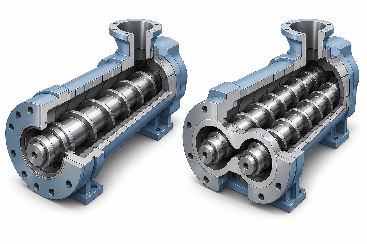
Single screw extruder barrel alignment is conceptually straightforward: one barrel bore centerline must be coaxial with one gearbox output shaft. The geometry involves a single axis of rotation, a single bore, and a relatively simple mechanical relationship. That simplicity, however, doesn't mean the alignment stays put on its own — and the primary reason it doesn't comes down to extruder barrel support system alignment.
Barrel supports are the unsung heroes (or villains) of single-screw alignment. Their job is to hold the barrel in its correct position while simultaneously allowing it to expand freely as it heats up. As Davis-Standard emphasizes, a barrel should never be locked down by a support that completely surrounds it — doing so prevents the barrel from sliding during thermal expansion and forces it to bend instead of growing straight.
Three common support designs serve this function, each with distinct alignment implications:
- Pedestal supports: Fixed upright mounts that cradle the barrel from below. Simple and robust, but they require properly machined contact surfaces and non-corrosive joint materials (such as brass) to prevent the barrel from "freezing" to the support as oxidation builds over time. A seized pedestal support is one of the most common causes of progressive alignment degradation.
- Roller cradle supports: Incorporate rollers or cylindrical bearings that allow the barrel to slide axially as it expands. These are well suited for longer barrels where thermal growth is significant, but the rollers themselves must remain clean, lubricated, and properly leveled to function correctly.
- Slide-plate supports: Use low-friction contact plates — often bronze or PTFE-faced — that let the barrel slide along a flat surface during expansion. These provide excellent freedom of movement but can wear or collect debris that increases friction over time, gradually restricting movement and introducing alignment drift.
Imagine a 4.5-inch, 36:1 barrel heated uniformly to 450°F. That barrel grows roughly 0.320 inches in length. If a support joint has seized or a slide plate has corroded, the barrel cannot expand in a straight line. It bends — and that bend is misalignment. You can verify whether your supports are functioning properly by opening the covers during heat-up and checking whether the fresh wear mark on the barrel corresponds to the calculated thermal expansion distance. A mismatch signals a support problem that's actively degrading your alignment.
For single-screw machines, Davis-Standard notes that extruders 3.5 inches (90 mm) or smaller rarely lose their factory alignment unless the L/D ratio is exceptionally long. Larger machines, however, sit on bases that are seldom rigid enough to hold alignment indefinitely — making periodic professional verification essential.
Twin-Screw Extruder Alignment Complexities
Twin-screw extruder alignment requirements escalate the challenge considerably. Instead of one bore aligned to one shaft, you're dealing with two parallel, intersecting bores that must maintain precise center-distance and twin screw barrel bore parallelism along the entire barrel length — all while remaining correctly oriented to the gearbox's twin output shafts.
Several factors make this inherently more complex:
Dual-bore geometry demands parallelism, not just concentricity. In a single-screw extruder, you're verifying one centerline against one reference axis. In a twin-screw machine, the two bore centerlines must remain parallel to each other at an exact center-to-center distance — typically held to tolerances measured in tenths of thousandths of an inch. Any deviation in parallelism changes the intermeshing clearance between the screws, which directly affects mixing performance, self-wiping behavior, and wear rates.
Segmented barrel designs multiply alignment variables. Most twin-screw extruders use modular, segmented barrels bolted together in sequence. Each barrel segment joint introduces an additional alignment interface where angular and offset deviations can accumulate. A small error at one joint compounds through subsequent segments, and the cumulative deviation at the discharge end can be many times larger than the error at any single joint. Verifying joint-to-joint alignment across all segments requires more measurement stations and more sophisticated analysis than a monolithic single-screw barrel.
Higher torque loads amplify consequences. Twin-screw extruders — particularly co-rotating designs used in compounding — operate under intense shear and torque conditions. As Technovel Corporation explains, co-rotating twin-screw extruders generate high shear stress between the screws and between each screw and the barrel, with mixing elements like kneading blocks adding further mechanical complexity. Misalignment under these loads accelerates wear dramatically and can damage expensive segmented barrel liners and screw elements far more quickly than equivalent misalignment would in a single-screw system.
Co-rotating vs. counter-rotating designs create different sensitivity profiles. Co-rotating machines run at higher speeds with intense intermeshing action, making them particularly sensitive to bore parallelism deviations — even small errors change the self-wiping clearance and alter the residence time distribution. Counter-rotating designs operate at lower speeds with a calendering-type intermeshing action, and while they're somewhat more forgiving of minor parallelism drift, the compressive forces at the intermeshing zone make them sensitive to center-distance errors that change the nip gap between screws.
To summarize these differences in a format you can reference when contacting alignment service providers, here are the key distinctions between single-screw and twin-screw alignment requirements:
- Number of bore centerlines: Single-screw involves one bore; twin-screw requires two parallel bores measured and corrected simultaneously
- Critical geometric relationship: Single-screw focuses on bore-to-shaft concentricity; twin-screw adds bore-to-bore parallelism and center-distance accuracy
- Barrel construction: Single-screw typically uses a monolithic barrel; twin-screw segmented designs add joint-to-joint alignment variables at every segment interface
- Thermal expansion behavior: Single-screw barrels expand along one axis; twin-screw barrels expand along two parallel axes, and differential expansion between the two bores can introduce parallelism errors
- Torque and load sensitivity: Twin-screw systems — especially co-rotating compounders — operate under higher mechanical loads, making them less tolerant of alignment deviations
- Measurement complexity: Twin-screw alignment requires more measurement stations, dual-bore reference mapping, and software capable of calculating parallelism deviations — not just single-axis offset
- Supplier expertise required: Not all alignment service providers have experience with twin-screw geometries; confirm specific twin-screw credentials before engaging a supplier for these machines
These architectural differences underscore a broader point: the type of extruder you operate directly shapes which alignment service suppliers are qualified to work on it. A provider's experience with your specific machine configuration — single-screw, co-rotating twin, counter-rotating twin, barrel length, and OEM brand — should be a primary qualification criterion, not an afterthought. That question of supplier evaluation is exactly where many buyers struggle most, and where a structured selection framework pays for itself many times over.
How to Evaluate and Select Alignment Service Suppliers
A structured selection framework sounds like a luxury — until you've spent $15,000 on a service visit that missed half the problem, or hired a team that had never worked on your extruder brand and made corrections based on assumptions rather than experience. Choosing the right extruder barrel alignment services suppliers is a procurement decision that directly affects your barrel and screw life, your energy costs, and your production uptime for months or years after the service truck leaves your plant. Yet most buyers approach this decision with less rigor than they'd apply to selecting a lubricant supplier.
The reason? There's no readily available guide that walks maintenance managers through how to choose an extruder alignment service provider with clear, objective criteria. The information that exists is either buried in technical engineering papers or wrapped in self-promotional language that obscures more than it reveals. This section fills that gap with a practical evaluation framework you can apply immediately.
Key Qualifications and Certifications to Look For
Not all alignment providers are created equal. The difference between a competent industrial shaft alignment company and a specialist qualified for extruder bore alignment is significant — and it's a distinction many buyers overlook because both use laser equipment and both call their work "alignment."
When evaluating extruder alignment supplier qualifications, prioritize these criteria:
- Extruder-specific experience: Ask how many extruder bore alignments the provider has performed, on which OEM brands (Davis-Standard, KraussMaffei, Coperion, Leistritz, etc.), and across which size ranges. General rotating-equipment alignment expertise does not automatically translate to proficiency inside an extruder barrel bore. The geometry, access constraints, and thermal behavior are fundamentally different from pump or compressor alignment.
- Laser alignment equipment quality and calibration records: Request documentation of the laser system they use — manufacturer, model, stated accuracy — along with current calibration certificates. A provider using uncalibrated or outdated laser equipment cannot guarantee that measurements fall within the claimed accuracy range. Systems from manufacturers like Pinpoint Laser Systems, Hamar Laser, or PRUFTECHNIK are industry-recognized for bore alignment applications.
- Technician training and certifications: Qualified technicians should hold certifications from their laser equipment manufacturer and, ideally, from the extruder OEM or an independent alignment training organization. Ask whether the specific technician assigned to your job — not just the company — has documented training on bore alignment procedures for your extruder type.
- Geographic service coverage and response time: Alignment is a scheduled service in most cases, but when a catastrophic wear event forces an emergency barrel change, you need a provider who can mobilize quickly. Understand whether the supplier serves your region with local technicians or dispatches from a distant hub, and clarify typical lead times for both planned and urgent service calls.
- References from similar operations: Request references from plants running the same extruder type, size, and processing application as yours. A provider who has aligned hundreds of pipe extrusion lines may have limited experience with the tight tolerances required for medical tubing or cast film applications.
- Comprehensive reporting capability: The ability to provide detailed alignment reports — with before-and-after measurement data, deviation plots, correction actions, and remaining tolerance status — is non-negotiable. Any provider who cannot deliver quantitative documentation should raise immediate red flags. As Davis-Standard recommends, alignment work should always be performed by certified technicians whose measurement data can be independently verified.
OEM Alignment Services vs Independent Specialists
One of the first decisions you'll face is whether to engage the extruder's original equipment manufacturer or hire an independent third-party alignment specialist. Both options have legitimate strengths, and the right choice depends on your specific priorities — budget, scheduling flexibility, machine complexity, and the scope of related services you need.
Here's an honest comparison across the criteria that matter most:
| Evaluation Criteria | OEM Alignment Services | Independent Specialists |
|---|---|---|
| Brand-Specific Expertise | Deep knowledge of their own machine designs, tolerances, and support system configurations | Varies widely; some independents specialize in specific OEM brands, others generalize across all makes |
| Cost | Typically higher; OEM labor rates and travel costs reflect brand premium | Generally more competitive; pricing varies by region and specialization level |
| Scheduling Flexibility | Limited availability — OEM field service teams serve large territories and may have multi-week lead times | Often more responsive; smaller teams can schedule with shorter notice and greater flexibility |
| Objectivity of Recommendations | May recommend OEM-branded replacement parts and services even when alternatives exist | More likely to offer brand-neutral recommendations based purely on measurement data |
| Geographic Coverage | National or global coverage, but concentrated around OEM service hubs | Regional focus is common; verify coverage for your specific plant locations |
| Scope of Related Services | Can often bundle alignment with barrel replacement, screw rebuilds, gearbox service, and controls upgrades | Alignment-focused; may lack in-house capability for barrel, screw, or gearbox work |
The trade-offs are real. OEM services — like those offered by Davis-Standard — bring unmatched machine-specific knowledge. Their technicians designed and built your extruder, so they understand its tolerances, support system design, and thermal expansion characteristics at a level an outsider simply cannot replicate. That depth of expertise is especially valuable for complex machines, twin-screw systems, or situations where alignment problems are intertwined with mechanical design questions.
Independent specialists, on the other hand, earn their place through flexibility, competitive pricing, and — in some cases — broader cross-brand experience that lets them spot patterns an OEM technician working on only one brand might miss. The key risk with independents is variability: the best ones rival OEM expertise, while the worst bring generic industrial alignment practices that don't account for extruder-specific challenges like thermal expansion, barrel support interaction, or bore-to-quill concentricity measurement.
Your vetting process should eliminate that variability risk by applying the qualification criteria above — regardless of whether the provider is an OEM or independent operation.
Evaluating Service Scope and Related Capabilities
Here's a practical consideration many buyers overlook: alignment rarely exists in isolation. When a technician confirms that your barrel bore has drifted 0.012 inches off the gearbox centerline, the immediate question is "fix the alignment." The follow-up question — equally important — is "how much damage did that misalignment cause to the barrel and screw before we caught it?"
The best extruder barrel alignment services suppliers offer integrated capabilities that extend beyond the alignment measurement itself. Look for providers who can also perform:
- Barrel bore inspection (boroscoping): Visual and dimensional inspection of the barrel bore interior to assess wear patterns, scoring, and remaining wall thickness — essential for determining whether the barrel can continue in service or needs relining or replacement
- Screw inspection and measurement: Flight diameter, root diameter, and hardness checks to quantify screw wear and determine whether the screw should be rebuilt, recoated, or replaced
- Wear analysis and root cause reporting: Connecting the alignment data to the observed wear patterns to confirm that misalignment was the cause and to prevent recurrence after correction
- Barrel and screw rebuilding or replacement: The ability to act on inspection findings — not just report them — by providing rebuilt or new barrels and screws matched to your application
This integrated approach matters because alignment correction without wear assessment is incomplete maintenance. You might achieve a perfect bore-to-shaft alignment, only to reinstall a screw whose flight tips have already worn past acceptable clearance from months of misaligned operation. Within weeks, the excessive clearance degrades output and melt quality — and the plant team blames the alignment service for failing to solve the problem.
Suppliers who combine alignment expertise with screw and barrel service capabilities can function as comprehensive maintenance partners. For example, NANHAIYA's screw and barrel services include custom screw design and alloy spray welding for wear restoration — capabilities that directly address the damage misalignment causes to screws and barrels. When evaluating providers, consider whether a supplier who can both diagnose alignment issues and restore or replace the worn components offers a more complete and efficient solution than coordinating separate vendors for each piece of the puzzle.
This single-source approach reduces coordination complexity, ensures that the screw and barrel specifications reflect the corrected alignment geometry, and gives one provider accountability for the complete outcome — from measurement through restoration to verified final alignment. It's the difference between hiring a diagnostician who hands you a report and partnering with a provider who solves the whole problem.
Of course, selecting the right supplier is only part of the equation. Understanding what actually happens during a professional alignment visit — and what your plant team needs to prepare — determines whether that carefully chosen provider can deliver the results you're paying for.
What to Expect During a Professional Alignment Visit
You've identified the warning signs, selected a qualified provider, and secured budget approval. Yet many plant teams hesitate at this final step — scheduling the actual service visit — because they don't know what the process involves, how long the extruder will be down, or what they're responsible for preparing. That uncertainty breeds delays, and delays let misalignment damage compound week after week.
Removing that information gap is straightforward. A professional extruder alignment visit follows a predictable, well-defined sequence, and your plant team's preparation directly influences how smoothly — and quickly — the work proceeds.
Pre-Visit Preparation and Plant Requirements
How to prepare for an extruder alignment service starts well before the technician's truck arrives at your loading dock. The more groundwork your team completes in advance, the less billable time gets spent on logistics rather than measurement and correction.
Here's what the alignment crew will need from you:
- Extruder cooled and locked out: The barrel must be at or near ambient temperature for accurate baseline measurements. Thermal expansion changes the barrel's geometry, so measuring a hot barrel produces data that doesn't reflect the machine's cold-start alignment condition. Follow your facility's lockout/tagout procedures on the drive system, barrel heaters, and any auxiliary equipment connected to the extruder.
- Barrel heating zone documentation: Provide a zone map showing the number, location, and rated wattage of each heater band, along with any known burned-out heaters or zones running at reduced capacity. This information helps the alignment technician evaluate whether uneven heating could be contributing to thermal distortion during operation.
- Screw removed from the barrel: Bore alignment measurements require an unobstructed barrel bore. Pull the screw prior to the visit and — while it's out — take the opportunity to photograph any visible wear patterns on the flights and root, as this evidence supports the technician's root cause analysis.
- Access scaffolding or platforms: On larger extruders, the barrel bore openings and support adjustment points may be several feet off the floor. Ensure that safe access platforms or scaffolding are in place before the crew arrives. Delays caused by waiting for scaffold erection eat into productive measurement time.
- Historical maintenance and wear records: Previous alignment reports, barrel bore measurements from boroscope inspections, screw measurement logs, and gearbox service records all give the technician context. A skilled provider doesn't just measure what exists today — they compare it against historical data to identify trends and rate of drift.
- Downstream equipment disconnected or documented: As Plastics Technology reports, heavy downstream components like screen changers and melt pumps can physically deflect the barrel when bolted in place. In one documented case, loosening a 4,000-lb screen changer from the barrel flange revealed a vertical barrel displacement of 0.255 inches and a lateral shift exceeding 0.100 inches. Your alignment provider will need to know what's attached and may require downstream equipment to be disconnected during measurement.
Scheduling coordination also deserves attention. Most professional extruder alignment process steps — from setup through final verification — require 6 to 12 hours of extruder downtime for a single-screw machine, depending on barrel length and the extent of corrections needed. Twin-screw extruders with segmented barrels often take longer due to the additional measurement stations and dual-bore geometry. Plan for a full production-day outage at minimum, and confirm the timeline with your provider during the quoting stage so that maintenance, production, and the alignment crew are all working from the same schedule.
The Alignment Process Step by Step
When the alignment technician arrives, the work unfolds in a structured sequence designed to establish a reference baseline, quantify deviations, make physical corrections, and verify the results. Knowing the extruder barrel alignment process steps in advance helps your maintenance team follow along intelligently and ask the right questions at each stage.
- Initial visual inspection and baseline assessment: The technician inspects the barrel supports, gearbox mounting, foundation condition, and overall machine geometry before touching any instruments. They're looking for obvious problems — seized support joints, cracked base welds, loose anchor bolts, or visible barrel sag — that would affect the measurement plan. Environmental conditions are also evaluated, since temperature fluctuations or heavy vibration from nearby equipment can influence laser measurement stability.
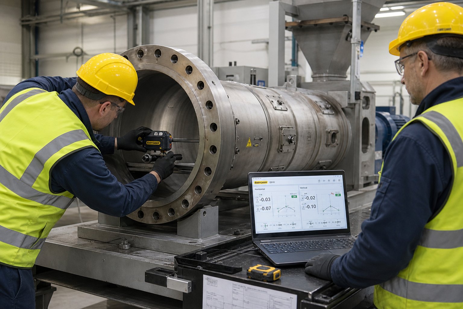
- Laser equipment setup and reference line establishment: A high-precision laser transmitter is mounted at the gearbox drive quill or at one end of the barrel bore, projecting a reference beam along the intended centerline. As Rotatek describes, this step creates a virtual datum line by referencing baseline bore centers, allowing the laser tracker to map the exact 3D position of all bores relative to this reference with sub-millimeter accuracy.
- Bore measurement at multiple barrel stations: Sensor targets or spherically mounted retroreflectors (SMRs) are positioned at multiple stations along the barrel bore length. At each station, the technician takes radial measurements from the bore interior surface, and the laser system records the vertical and horizontal offset of each point from the reference centerline. More stations mean higher resolution — especially important on long barrels where deviations can change direction along the length.
- Data collection and software analysis: Measurement data feeds into alignment software that calculates angular and offset deviations at each station, generates deviation plots, and identifies exactly where and how much the bore deviates from the ideal coaxial relationship with the gearbox output shaft. Real-time data analysis enables the technician to see the full picture before making any physical changes — preventing trial-and-error adjustments that can introduce new problems.
- Physical adjustment of barrel supports and gearbox mounting: Based on the deviation data, the technician makes calculated corrections. This may involve shimming barrel supports, adjusting support heights, repositioning the gearbox on its mounting base, or correcting base-frame irregularities. Each adjustment targets a specific measured deviation rather than relying on feel or visual assessment. If the gearbox position is moved to correct its relationship with the barrel, a follow-up motor-to-gearbox coupling alignment is performed as a mandatory secondary step.
- Verification measurements to confirm corrections: A complete re-measurement pass is performed after all adjustments are finalized. This verification confirms that the corrections achieved the target tolerances and that no new deviations were introduced during the adjustment process. The before-and-after data set is the proof that the work succeeded — without it, you're relying on faith rather than measurement.
- Final reporting and recommendations: The technician compiles all data into a formal alignment report and reviews the findings with your maintenance team on-site. This debrief covers what was found, what was corrected, any remaining conditions that fall outside ideal tolerances, and recommendations for follow-up actions or monitoring intervals.
The entire sequence is methodical and data-driven. A professional extruder alignment visit expectations should center on transparency — you should be able to watch the measurements, see the deviation plots in real time, and understand the rationale behind every physical adjustment before it's made.
Deliverables and Documentation You Should Receive
The alignment report is not a nice-to-have — it's the primary deliverable that separates a professional service from a best-guess adjustment. Extruder alignment service report deliverables should include, at minimum:
- Before-and-after measurement data: Raw numerical readings at each measurement station, showing the barrel bore position relative to the gearbox centerline reference before any corrections and after all corrections were completed
- Deviation plots: Graphical representations — typically horizontal and vertical deviation charts plotted along the barrel length — that make it visually clear where the bore was out of tolerance and how far corrections brought it back
- Correction actions taken: A detailed record of what was physically adjusted — which supports were shimmed and by how much, whether the gearbox was repositioned, and what secondary alignments (motor-to-gearbox coupling) were performed as a result
- Remaining tolerance status: An honest assessment of the final alignment condition, including any residual deviations that fall within acceptable tolerances but should be monitored, and any conditions that could not be fully corrected during this visit (such as foundation issues requiring structural work)
- Recommendations for future monitoring intervals: A suggested schedule for the next alignment check based on the machine's operating conditions, the severity of the deviations found, and the rate of drift inferred from comparison with any prior alignment data
Thorough documentation is a key differentiator between professional alignment suppliers and less rigorous operators. A provider who delivers a one-page summary stating "alignment corrected — within tolerance" without supporting measurement data has given you nothing you can verify, trend over time, or use to hold them accountable if problems recur. Require comprehensive reporting in your service agreement before the work begins — not as an afterthought when the invoice arrives.
This documentation also serves a forward-looking purpose. Each alignment report becomes a data point in your extruder's maintenance history. Over successive service visits, you'll build a trend line that reveals how quickly alignment drifts under your specific operating conditions — information that lets you optimize the interval between preventive alignment checks and justify the investment with hard data rather than assumptions. That question of investment justification — proving the financial return of professional alignment services — is precisely where many maintenance managers find themselves needing the strongest possible business case.
The ROI of Professional Barrel Alignment Services
Hard data beats assumptions — especially when you're standing in front of a plant manager defending a line item on next quarter's maintenance budget. Most maintenance managers intuitively understand that misalignment is bad, but intuition doesn't approve purchase orders. What does? A clear financial case showing that the cost of extruder barrel misalignment dwarfs the cost of preventing it. Yet surprisingly few resources spell out that case in concrete terms, leaving procurement teams to argue from gut feeling rather than numbers.
Let's fix that.
Cost of Misalignment in Barrel and Screw Wear
The financial consequences of operating a misaligned extruder accumulate across four major cost categories — each one substantial on its own, and devastating in combination.
Accelerated barrel and screw replacement costs hit the budget hardest. A properly aligned barrel-and-screw set in a typical plastics extrusion application might last 5 to 8 years depending on materials processed. Misalignment can cut that life in half or worse by forcing the screw into one-sided contact with the barrel bore. You're not just buying replacements more often — you're paying for emergency procurement, expedited shipping, and the production lost during unplanned changeouts. Davis-Standard notes that misalignment causes premature wear, bent and broken screws, and unstable barrels — each of which triggers a costly repair cycle that proper alignment would have prevented.
Increased energy consumption is a persistent drain that rarely gets attributed to alignment. A screw dragging against the barrel wall encounters higher frictional resistance, and the drive motor compensates by drawing more current. On a large extruder running 24/7, even a 5-10% increase in motor amperage translates into thousands of dollars in excess electricity annually — money that quietly disappears into the utility bill without anyone connecting it to a mechanical root cause.
Elevated scrap rates compound the loss. Misalignment-driven melt pressure instability, surging, and poor homogeneity produce off-spec product that either gets scrapped or downgraded. If your scrap rate climbs from 2% to 4% because of alignment-related quality issues, you've doubled your material waste on every production run.
Unplanned downtime from premature component failures is often the most expensive category of all. A thrust bearing that fails catastrophically because it's been absorbing abnormal radial loads doesn't just cost the price of the bearing — it costs the value of every hour of production lost while the gearbox is torn apart for repair. Industry reliability experts consistently emphasize that unplanned maintenance is the most expensive and dangerous way to operate, because the machine dictates the schedule instead of the maintenance team.
Every facility's numbers are different, so calculate your own: multiply your barrel and screw replacement cost by how frequently you're replacing them, add the annual energy premium from elevated motor loads, factor in your scrap cost per percentage point, and estimate the hourly production value lost during unplanned shutdowns. The total almost always justifies professional alignment several times over.
Professional Alignment vs In-House Attempts
Some plants try to avoid the service cost by performing alignment checks internally. The intention is sound — but the execution almost always falls short, and the resulting false confidence can be more expensive than doing nothing at all.
Why do in-house attempts typically fail? Three reasons stand out. First, specialized laser bore alignment equipment costs tens of thousands of dollars — an investment that's difficult to justify for a tool you might use once or twice a year. Without it, teams default to levels, straightedges, or dial indicators that simply cannot measure bore-to-shaft concentricity with the precision required. Second, interpreting barrel bore deviation data requires specific training that general maintenance technicians don't possess. Knowing that the bore is 0.008 inches offset at station three means nothing without understanding whether to adjust the support at station two or reposition the gearbox — and making the wrong call can create new deviations that compound the original problem. Third, accountability evaporates when the same team that performed the alignment is also responsible for evaluating its success. Professional providers stake their reputation on documented results; internal teams rarely produce the same level of rigorous before-and-after measurement records.
The ROI of extruder alignment services becomes clearest when you tally up the hidden costs that deferred or amateur alignment generates over time:
- Repeated barrel and screw replacements: Installing new components into a barrel that's still misaligned starts the wear clock over at an accelerated rate, creating a cycle of premature replacements that never addresses the root cause
- Chronic quality issues: Persistent surging, gauge variation, and melt inconsistency that get managed through process workarounds — slower line speeds, tighter operator monitoring, increased QC inspection — rather than eliminated at the source
- Excess energy spend: Ongoing elevated motor loads that become the "new normal" because no one connects the amperage creep to a mechanical alignment condition
- Reactive maintenance cycles: A pattern where the team responds to symptoms — replacing bearings, swapping screws, adjusting barrel heaters — without diagnosing the underlying alignment problem that's driving all of them simultaneously
Each of these hidden costs compounds over months and years. A single professional alignment service, by contrast, addresses the root cause in a day and produces documented results you can verify and trend over time.
Building the Business Case for Preventive Alignment
The strongest business case for extruder barrel alignment reframes it from a repair expense to a preventive maintenance investment — the same category as oil analysis, vibration monitoring, or thermographic inspection. The logic is straightforward: spend a known, modest amount on scheduled alignment verification to avoid an unknown, much larger amount in unplanned repairs, lost production, and wasted material.
Here's a framework for building that case for extruder barrel alignment within your organization:
Quantify your current replacement costs. Pull purchase records for barrel and screw replacements over the past three to five years. Calculate the average replacement interval and compare it against the manufacturer's expected service life. If you're replacing components 30-50% sooner than expected, misalignment is a prime suspect — and the gap between actual and expected life represents your addressable savings.
Document energy baselines. Record motor amperage at rated screw speed on a freshly aligned machine, then track it over time. Progressive amperage creep provides both a diagnostic indicator and a dollar figure you can attach to the alignment business case.
Calculate scrap cost sensitivity. Even a half-percentage-point reduction in scrap rate yields measurable savings on high-volume lines. Tie this to alignment by correlating scrap trends with alignment service dates — if scrap drops after alignment and climbs between services, the relationship becomes self-evident.
Establish recommended alignment intervals. Extruder alignment preventive maintenance savings grow when you shift from reactive to scheduled verification. As a starting framework, consider these interval guidelines based on operating conditions:
- Standard processing (unfilled polymers, moderate temperatures): Alignment verification every 18 to 24 months
- Abrasive or corrosive processing (glass-filled, mineral-filled, or fluoropolymers): Every 12 to 18 months, as accelerated wear amplifies the consequences of even minor misalignment
- High-precision applications (medical tubing, optical film, tight-tolerance profiles): Every 12 months or after any barrel or screw changeout, because these applications are least tolerant of the melt inconsistency that misalignment causes
- Large extruders on flexible foundations (6-inch and above): Every 12 months regardless of application, because foundation drift is a persistent factor that increases with machine size
Present the case to management as a comparison: the annual cost of scheduled alignment verification (typically one to two service visits per machine) versus the documented annual cost of the replacement, energy, scrap, and downtime consequences that misalignment produces. When the numbers are laid out side by side, the decision becomes obvious — and the maintenance team shifts from defending the expense to demonstrating the savings.
Of course, the most compelling business case in the world loses credibility if you can't verify that the alignment service actually achieved its targets. Knowing the tolerance specifications your extruder demands — and understanding how to read the measurement data in an alignment report — gives you the tools to hold any provider accountable for measurable results.
Alignment Tolerances and Quality Verification Standards
Holding a provider accountable requires more than good intentions — it requires a yardstick. And in extruder barrel alignment, that yardstick is defined by tolerance specifications: quantitative limits that separate "aligned" from "not aligned" in terms your procurement team, your maintenance engineers, and your alignment supplier all agree on before the work begins. Yet extruder barrel alignment tolerance specifications are among the least-discussed topics in the extrusion maintenance world. OEM manuals rarely spell them out in plain language. Service providers quote results in technical shorthand that few buyers know how to interpret. The result is an accountability gap where plants pay for alignment services but lack the knowledge to verify whether the reported measurements actually represent acceptable performance.
Closing that gap puts the purchasing power back in your hands.
Industry Tolerance Standards for Barrel Bore Alignment
Barrel bore alignment quality is measured using a concept called Total Indicator Reading, or TIR. Imagine a dial indicator or laser sensor positioned inside the barrel bore at a given station along its length. As the sensor sweeps the full circumference of the bore at that point, the difference between the highest and lowest readings is the TIR — a single number, expressed in thousandths of an inch (mils), that captures how far the bore center at that station deviates from the reference centerline established by the gearbox drive quill.
A perfect TIR reading of zero would mean the bore center sits exactly on the reference axis. In the real world, zero isn't achievable or even necessary. What matters is that the TIR at every measurement station falls within the acceptable range for your barrel diameter, barrel length, and application requirements.
General tolerance principles for barrel bore alignment TIR standards follow a logical pattern:
- Smaller barrels (under 3.5 inches / 90 mm): These machines have shorter spans and stiffer barrel assemblies, so they tend to hold factory alignment well. Typical acceptable TIR values range from 0.002 to 0.004 inches at any measurement station along the bore length. As Davis-Standard notes, alignment verification on extruders this size is often considered redundant unless the L/D ratio is exceptionally long.
- Mid-range barrels (3.5 to 6 inches): Foundation flexibility and barrel support degradation become more significant at these sizes. Target TIR values of 0.003 to 0.005 inches are common, with tighter limits applied at the feed throat and discharge ends where screw-to-barrel clearance is most critical for process stability.
- Large barrels (6 inches and above): Longer spans, heavier thermal loads, and more flexible base frames make these the most alignment-sensitive machines. TIR targets of 0.004 to 0.006 inches are typical, but even these values represent tight control given the barrel lengths involved — often exceeding 15 feet.
Angular deviation is the other key metric. While TIR captures how far the bore center is offset at a single station, angular deviation measures how rapidly that offset changes per unit of barrel length — expressed in mils per inch or mils per foot. A barrel that's uniformly offset by 0.004 inches along its entire length presents a different (and less damaging) condition than a barrel that swings from 0.001 inches offset at the feed end to 0.008 inches at the discharge end. The second scenario concentrates deflection forces at the transition point, accelerating localized wear far more aggressively than a uniform offset of the same magnitude.
Most professional alignment providers target angular deviations no greater than 0.0005 to 0.001 inches per inch of barrel length. Values exceeding this range indicate a barrel support problem, a foundation issue, or a barrel bore that has permanently deformed — each requiring a different corrective approach.
One critical nuance: these tolerance ranges are guidelines, not universal standards published in a single ASTM or ISO document. Extruder barrel alignment tolerances are largely governed by OEM specifications, which vary between manufacturers, and by application-specific requirements driven by the precision demands of the end product. High-precision film lines and medical tubing extrusion demand tighter tolerances — often half the values listed above — because even minor melt flow inconsistency shows up as visible defects in the finished product. General-purpose profile extrusion or pipe production can operate successfully with slightly wider tolerances because the end products are more forgiving of small melt variations.
When engaging a service provider, ask explicitly which tolerance standard they'll be working to — their own internal standard, the OEM's published specification, or a mutually agreed target based on your application. Getting that agreement documented before the service visit prevents disputes when the final report arrives.
How to Read and Verify an Alignment Service Report
You've received a multi-page alignment report full of numbers, charts, and technical terminology. How do you know whether it actually confirms that your extruder is properly aligned? Learning how to read an extruder alignment report isn't as daunting as it first appears — it comes down to understanding four elements.
Deviation plots are the most informative section of any report. These are graphical charts — typically one for the horizontal plane and one for the vertical plane — that plot bore center position along the Y-axis against barrel length (measurement station locations) along the X-axis. A perfectly aligned bore would produce a flat line at zero. Real-world results show a line that wanders above and below zero, with each peak and valley representing the offset at that station. What you're looking for is whether all the plotted points fall within the tolerance band — usually shown as shaded regions or dashed lines on either side of zero. Points inside the band mean that station passed. Points outside mean deviations persist.
Compare the "before" and "after" deviation plots side by side. The before plot shows the alignment condition as found — this is the data that documents the problem. The after plot shows the condition following corrections. You should see the after plot significantly flattened compared to the before plot, with all stations ideally falling within the tolerance band. If the after plot still shows stations outside tolerance, the report should explain why — a foundation condition that requires structural work, a barrel bore that has permanently deformed beyond what support adjustments can correct, or a segment joint (in twin-screw machines) that needs disassembly and remachining.
Numerical measurement data backs up the graphical plots. Each station should have recorded values for horizontal offset, vertical offset, and the combined TIR or radial deviation. Spot-check these numbers against the plotted points to confirm internal consistency. If the plot shows a station inside tolerance but the raw data shows a TIR of 0.008 inches when the agreed tolerance is 0.005, that discrepancy deserves a question.
Correction actions should be documented in detail. A quality report tells you not just what was measured but what was physically changed: which barrel supports were shimmed and by how much, whether the gearbox was repositioned, and what secondary alignments were performed. This record matters for future reference — the next time alignment is checked, the technician can see what was done previously and evaluate whether corrections have held or drifted.
Remaining issues and recommendations are where honest providers distinguish themselves from ones just trying to close the job. Every alignment visit doesn't end with a perfect result. Perhaps one barrel support pedestal is corroded beyond adjustment and needs replacement before the barrel can be fully corrected. Maybe the foundation has settled unevenly and requires grouting before alignment improvements will hold long-term. A trustworthy report flags these conditions transparently, gives you a recommended timeline for addressing them, and suggests when the next alignment verification should be scheduled.
Alignment is verified by measurement data, not by visual inspection. Any supplier unable to provide quantitative before-and-after measurement records with deviation plots and documented correction actions should be viewed with skepticism — regardless of how confident their technician appears on-site.
A practical verification step you can apply immediately: request that the alignment provider walk your maintenance team through the report on-site before they leave. Ask them to point to the before-and-after deviation plots, identify any stations that remain outside tolerance, and explain the physical corrections that produced the measured improvements. A provider who can do this clearly and confidently has done the work properly. One who rushes through the report or deflects questions may be hiding incomplete results behind technical jargon.
Remember, too, that tolerance specifications are not one-size-fits-all. If your line produces medical-grade tubing where wall thickness variation is measured in tenths of a mil, the alignment tolerances that matter to you are substantially tighter than those acceptable for a commodity pipe operation. Make sure your service agreement specifies the tolerance standard appropriate for your application — and that the final report demonstrates compliance against that specific standard, not a looser generic benchmark.
Equipped with this knowledge, you can read an alignment report critically, verify that corrections met your required specifications, and identify any remaining conditions that need follow-up. That verification capability transforms alignment from a trust-based transaction into a measurable, accountable service — and it sets the stage for integrating alignment into a broader preventive maintenance strategy where every service builds on documented data from the one before it.
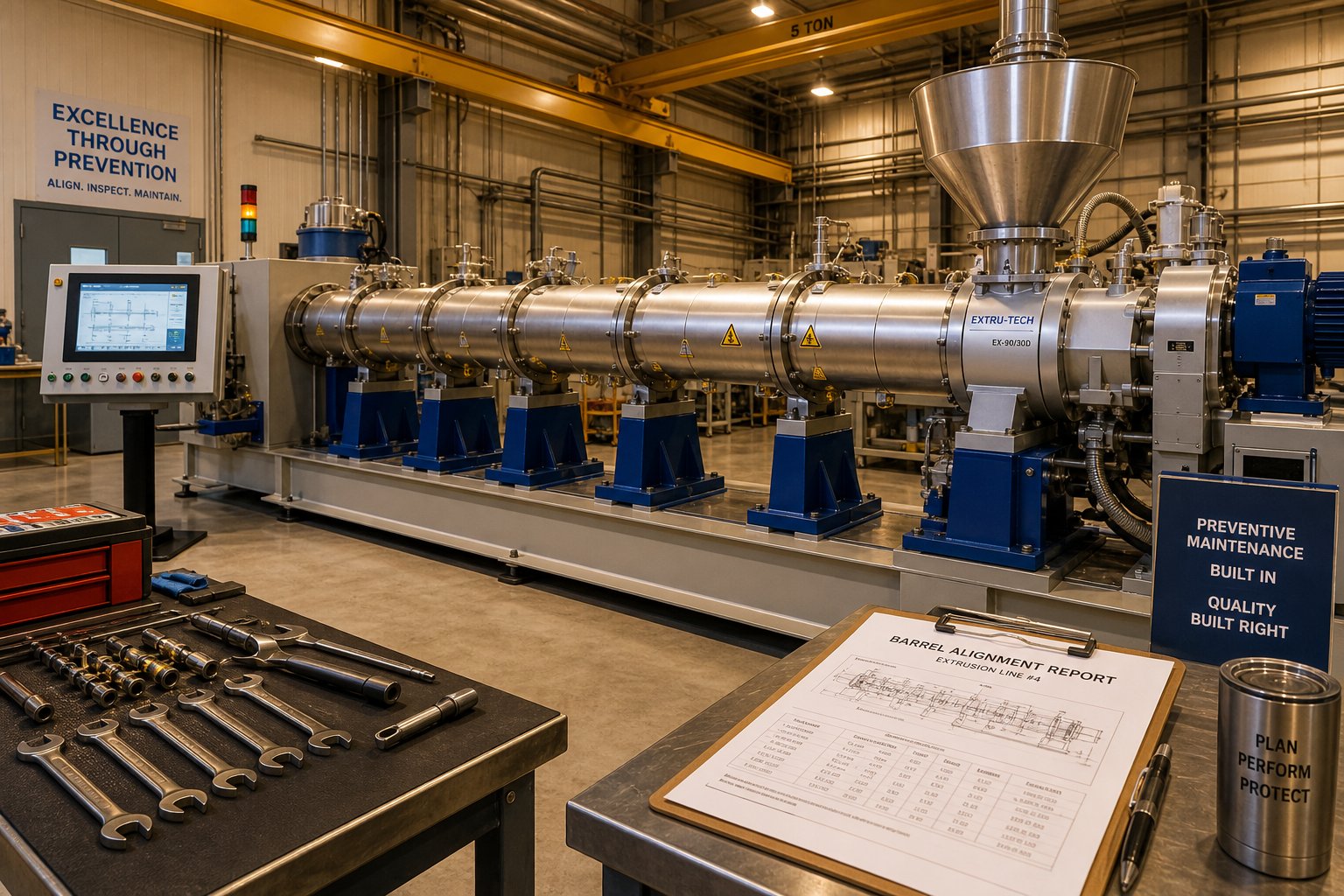
Building a Long-Term Alignment and Maintenance Partnership
Verified alignment data on file, tolerances confirmed, deviation plots trending in the right direction — that's a strong position. But here's the honest reality: alignment correction in isolation is a temporary fix if the broader maintenance ecosystem around your extruder isn't equally disciplined. A barrel that's been laser-aligned to 0.003 inches TIR today can drift back toward trouble within months if worn barrel supports go unreplaced, if a screw with compromised flight tips gets reinstalled, or if gearbox bearing degradation introduces new radial loads that shift the geometry all over again.
The most reliable extrusion operations don't treat alignment as a standalone event. They embed it within a preventive extruder alignment maintenance program that connects every critical maintenance activity — alignment, wear monitoring, component inspection, and rebuild or replacement decisions — into a unified strategy where each service informs the next.
Alignment as Part of a Comprehensive Maintenance Program
Imagine aligning your barrel bore perfectly, reinstalling the screw, and returning to production — only to find that melt quality degrades within weeks. What happened? The screw you reinstalled had flight tip wear that opened the screw-to-barrel clearance beyond the threshold where alignment corrections actually matter. Or the barrel bore itself had developed localized erosion in the transition zone that no amount of support shimming can fix. These are not hypothetical scenarios — they're among the most common reasons alignment services appear to "fail" when the alignment itself was technically flawless.
The lesson is structural: barrel alignment connects mechanically and diagnostically to a network of related maintenance activities, and addressing one without inspecting the others produces incomplete outcomes. Here's how those connections work in practice:
Barrel bore inspection via boroscoping should accompany every alignment service, or at minimum every other service visit. A boroscope examination reveals internal bore conditions — scoring, erosion, bimetallic liner delamination, and corrosion patterns — that alignment measurements alone cannot detect. A bore that measures perfectly straight can still have localized wall thinning that changes screw clearance and undermines melt conveyance. As Plastics Technology emphasizes, barrel I.D. surface condition is a direct factor in wear progression, and documenting that condition during alignment visits creates a comprehensive picture no single measurement type provides alone.
Screw flight and root diameter measurement quantifies how much wear the screw has accumulated since its last installation or rebuild. Flight outside diameter determines the functional clearance between screw and barrel — the very gap that alignment is designed to keep uniform. If flight tips have worn 0.010 inches beyond the design clearance, even a perfectly aligned barrel cannot restore the shear rate and heat transfer characteristics the process requires. Measuring both the screw and the barrel bore during the same service window lets your maintenance team make a go/no-go decision on screw serviceability before reinstallation, rather than discovering the problem through poor product quality weeks later.
Wear analysis to determine rebuild or replacement needs closes the loop between diagnosis and action. When alignment data reveals that the barrel drifted 0.012 inches off-axis over the past 18 months, and boroscope inspection shows corresponding one-sided bore erosion, the maintenance decision tree becomes clear: correct the alignment, and either reline the barrel or replace it depending on remaining wall thickness. Similarly, screw wear patterns confirmed by dimensional measurement determine whether the screw needs hardfacing restoration, alloy spray welding to rebuild flight tips, or full replacement with a design optimized for the current material and throughput requirements. That recommendation from industry maintenance experts — to use wear measurements as the basis for deciding where premium metallurgy or component replacement is needed — applies equally to plastics extrusion and food processing extrusion platforms.
Gearbox inspection rounds out the system-level view. Misalignment imposes abnormal radial and thrust loads on gearbox bearings and output shaft seals. Even after the barrel is realigned, bearings that absorbed months of excessive loading may have reduced remaining life. A vibration analysis or bearing condition assessment during the alignment visit identifies gearbox components that are approaching failure — preventing the unplanned downtime that a catastrophic bearing seizure would cause weeks after the alignment crew has left.
The thread connecting all of these activities is data continuity. Each inspection generates measurements that become reference points for the next service cycle. Barrel bore diameter readings from today's boroscope inspection become the comparison baseline for next year's check. Screw flight measurements taken during this alignment visit reveal the wear rate that determines when the next rebuild should be scheduled. Alignment deviation trends across multiple service visits expose whether foundation drift is accelerating, whether a specific barrel support is consistently problematic, or whether a particular heating zone creates recurring thermal distortion. Without this longitudinal data, every service visit starts from scratch — and every maintenance decision relies on guesswork rather than evidence.
Choosing a Service Partner for the Long Term
This comprehensive approach to extruder alignment and maintenance partnership demands a supplier relationship that goes beyond transactional service calls. You're not just buying a measurement — you're investing in a long term extruder barrel maintenance supplier who understands your equipment history, recognizes your evolving wear patterns, and can act on inspection findings without requiring you to coordinate three separate vendors for alignment, bore inspection, and component restoration.
The evaluation criteria discussed throughout this article converge into a final selection framework. When choosing a service partner for the long term, weigh each provider against these integrated capabilities:
- Laser alignment capability: Verified bore alignment equipment with current calibration records, technicians trained on your extruder type, and the ability to perform bore, coupling, and foundation alignment as an integrated service — not isolated checks billed separately
- Bore inspection services: Boroscoping, bore diameter measurement, and surface condition assessment to evaluate barrel wear in conjunction with alignment data, providing a complete diagnostic picture during a single service visit
- Screw and barrel rebuild or replacement capacity: The in-house ability to restore worn components — through bimetallic relining, hardfacing, or alloy spray welding for flight tip rebuilding — or to supply new barrels and screws when wear exceeds rebuildable limits
- Custom design engineering: Capability to optimize screw geometry for your specific material, throughput, and quality requirements — especially important when alignment corrections reveal that the original screw design was contributing to uneven wear patterns or processing limitations
- Geographic responsiveness: Service coverage that supports both scheduled preventive visits and urgent response when unplanned events require rapid mobilization — without excessive travel surcharges that inflate the per-visit cost
- Documentation quality: Comprehensive reporting with before-and-after measurement data, deviation plots, correction records, and trending capability across multiple service visits — the foundation of data-driven maintenance decision-making
Few providers check every box on this list. OEM service departments excel at machine-specific alignment knowledge but may lack the screw and barrel manufacturing flexibility to offer custom rebuild solutions. Dedicated alignment companies bring measurement precision but often can't act on the wear conditions their data uncovers. The providers that deliver the most value are those who combine comprehensive extruder screw and barrel services with alignment expertise — or who have established partnerships that let them coordinate the full scope without burdening your procurement team with multi-vendor logistics.
Suppliers like NANHAIYA illustrate this integrated model. Their service platform combines custom screw design, alloy spray welding for wear restoration, and full barrel and screw service support — capabilities that directly address the wear damage alignment problems cause. When your alignment report reveals one-sided barrel erosion and screw flight degradation, a partner with this scope of services can move from diagnosis to component restoration without handing you off to a separate vendor for each step. That continuity ensures the rebuilt screw dimensions reflect the corrected alignment geometry, the barrel bore condition matches the screw clearances, and one provider owns accountability for the complete outcome.
This principle — that the best alignment outcomes come from suppliers who understand the complete barrel-and-screw system, not just the alignment measurement itself — should guide your selection process regardless of which specific provider you ultimately engage. A technician who knows how screw design affects wear patterns, how barrel metallurgy influences bore degradation, and how thermal expansion interacts with support system design will deliver more actionable alignment data than one who treats the bore as an abstract geometric exercise disconnected from the components operating inside it.
Frame the decision as a long-term partnership rather than a one-time transaction. The first alignment visit establishes a baseline. The second visit reveals drift rates. The third visit confirms whether corrective actions held and identifies emerging issues before they escalate. Over time, your service partner accumulates institutional knowledge about your specific machines, your operating conditions, and your facility's maintenance patterns — knowledge that improves the precision and relevance of their recommendations with every visit. That compounding expertise is the real return on a partnership investment, and it's something you cannot replicate by rebidding the work to the lowest-cost provider every cycle.
Extruder barrel alignment is not a one-and-done repair. It's a recurring discipline embedded within a broader system of preventive maintenance activities — bore inspection, screw measurement, wear analysis, component restoration, and gearbox monitoring — that collectively protect the most expensive and performance-critical components in your extrusion line. The suppliers who earn your long-term business are those who understand that system completely, who document their work rigorously, and who treat every service visit as a chapter in your equipment's ongoing story rather than an isolated transaction. Choose partners accordingly, and the costly downtime that brought you to this article becomes the exception rather than the expectation.
Frequently Asked Questions About Extruder Barrel Alignment Services
1. How often should extruder barrel alignment be checked?
Alignment verification frequency depends on your operating conditions. For standard unfilled polymer processing, every 18 to 24 months is a reasonable interval. Abrasive or glass-filled material applications warrant checks every 12 to 18 months because accelerated wear magnifies the impact of even slight misalignment. High-precision lines producing medical tubing or optical film should be verified annually or after every barrel or screw changeout. Large extruders (6 inches and above) sitting on flexible foundations benefit from annual checks regardless of the material processed, since foundation drift is a persistent concern that worsens with machine size.
2. What is the difference between bore alignment and coupling alignment on an extruder?
Bore alignment verifies that the barrel bore centerline is straight and concentric with the gearbox output shaft along the entire barrel length. It confirms that the internal tunnel the screw travels through points in exactly the right direction relative to the drive quill. Coupling alignment, on the other hand, focuses on the mechanical connection points — the gearbox-to-barrel flange joint and the motor-to-gearbox coupling — ensuring that two joined rotating components share the same rotational axis. A comprehensive alignment service addresses both as an integrated system, because correcting bore position without verifying coupling geometry, or vice versa, can leave residual deviations that continue to cause wear and vibration.
3. How much does extruder barrel misalignment cost a plant?
The true cost spans four major categories that compound over time. Accelerated barrel and screw wear shortens replacement intervals — potentially cutting component life by 50% or more — driving up capital expenditure on premature replacements. Elevated motor amperage from a screw dragging against the barrel wall can add thousands of dollars in annual energy costs on a 24/7 production line. Scrap rates climb as misalignment causes melt pressure instability, surging, and poor homogeneity, doubling material waste in some cases. Finally, unplanned downtime from catastrophic bearing or screw failures represents lost production revenue that often dwarfs the cost of the failed component itself. Calculating facility-specific numbers across these categories almost always reveals that preventive alignment pays for itself multiple times over.
4. Can extruder barrel alignment be done in-house instead of hiring a professional service?
While the intention is understandable, in-house alignment attempts typically fall short for three key reasons. First, professional laser bore alignment systems cost tens of thousands of dollars, making them hard to justify for equipment used once or twice a year. Without them, teams default to levels, straightedges, or dial indicators that lack the precision needed for bore-to-shaft concentricity measurement. Second, interpreting bore deviation data and determining which supports to shim or whether to reposition the gearbox requires specialized training most general maintenance technicians do not have — incorrect adjustments can create new deviations that worsen the original problem. Third, internal teams rarely produce the rigorous before-and-after measurement documentation that professional providers deliver, eliminating the accountability and trending data that make alignment a measurable, repeatable discipline.
5. What should I look for in an extruder barrel alignment service report?
A quality alignment report should contain five key elements: before-and-after measurement data at each barrel station showing bore position relative to the gearbox centerline; deviation plots graphing horizontal and vertical offset along the barrel length with tolerance bands clearly marked; a detailed record of correction actions including which supports were shimmed, gearbox repositioning details, and any secondary motor-to-gearbox coupling alignment performed; an honest assessment of remaining tolerance status including any residual deviations or conditions that could not be fully corrected; and recommendations for future monitoring intervals based on operating severity and observed drift rates. Suppliers like NANHAIYA (nhyscrews.com/services), who combine alignment expertise with screw and barrel rebuild capabilities, can further enhance report value by correlating alignment findings with wear analysis and component restoration recommendations in a single service framework.
Written by
Nanhaiya Technical Team
Zhoushan Nanhaiya Plastic Machinery Co., Ltd.
The Nanhaiya technical team supports screw and barrel manufacturing projects through application review, technical communication, custom manufacturing coordination, and production and quality control.
Discuss Your Application
Related Articles
More insights on screw barrel technology and plastics processing.

What Nobody Tells You About Screw Barrel For Plastic Machine Design
Oct 10, 2026
Learn how screw barrel for plastic machine design affects melt quality, throughput, and wear life. Covers geometry, resin matching, troubleshooting, and sourcing.
Read Article
Single Screw Extruder for Sheet: Stop Guessing, Start Specifying
Oct 9, 2026
Learn how to specify a single screw extruder for sheet production. Covers screw geometry, resin-specific processing, troubleshooting, and maintenance best practices.
Read Article
PE Pipe Extruder Machine: What Datasheets Won't Tell You
Oct 9, 2026
Learn how a PE pipe extruder machine works, key specs explained, material grade selection, maintenance tips, and buyer guidance beyond the datasheet.
Read ArticleLooking for something else?
Search by material, symptom or product and jump straight to the relevant page.
These are navigation suggestions based on keyword matching — not a quotation, not a delivery commitment, and not a substitute for engineering review. Final specification is confirmed by our engineers against your drawings and processed material.
Need help with screw barrel selection?
Share your machine model, processed material and application. Our team can help with pricing and technical support.