

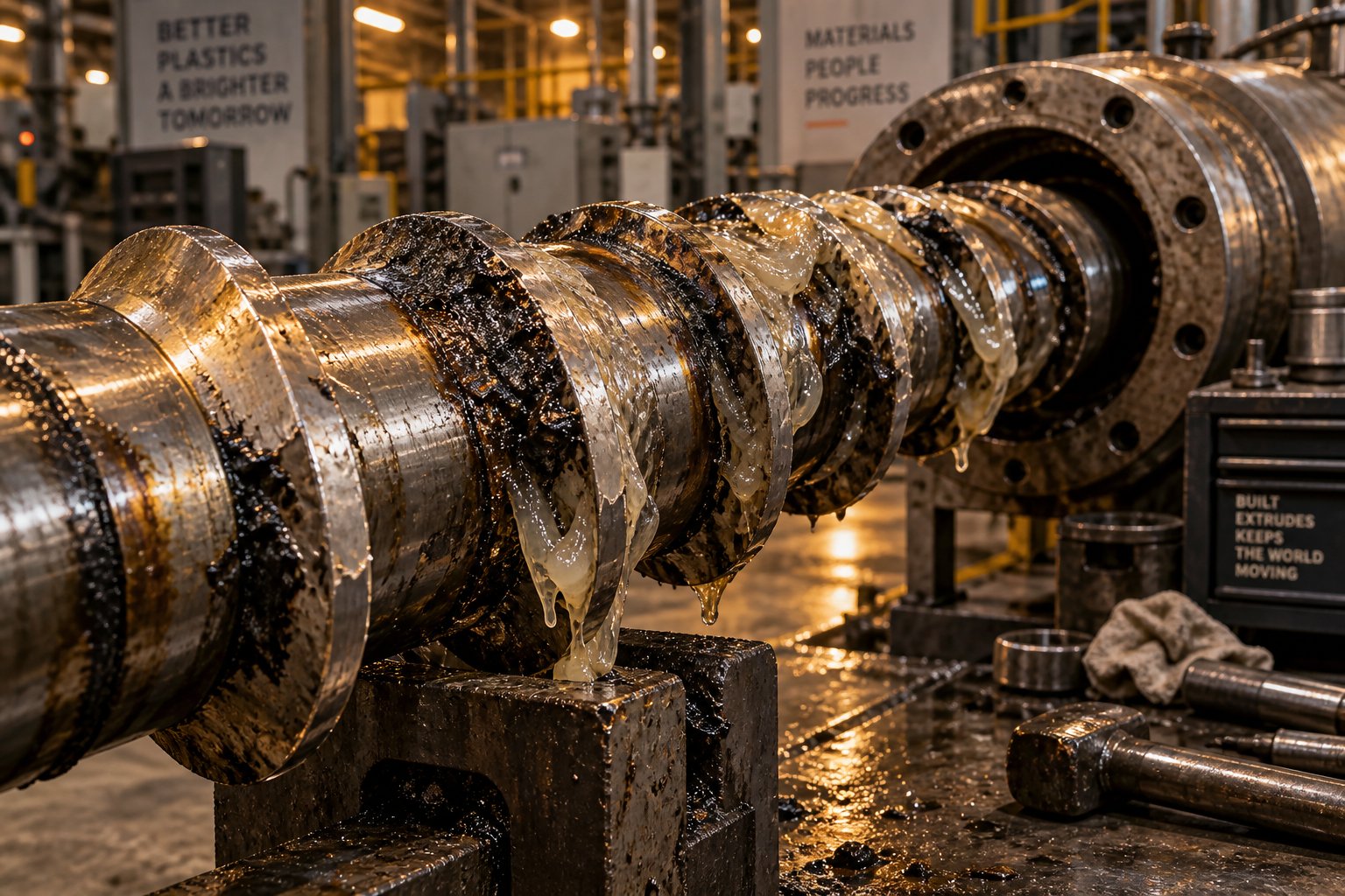
警告信号:背压正在损害您的输出
你的挤出机出了问题。可能是出料量突然增加,或者3D打印机的步进电机咔哒作响,把耗材磨成粉末。打印出来的零件壁厚不均匀,或者打印件上出现莫名其妙的缝隙,缝隙后面还跟着一团团过度挤出的材料。你已经调整过温度,更换过耗材卷轴,拧紧过所有能拧的螺丝——但问题依然存在。
大多数操作人员和业余爱好者都忽略了一点:这些症状往往源于同一个根本原因。挤出机背压问题在工业生产车间和桌面3D打印机上的表现形式不同,但其基本物理原理却是一样的。熔体路径上的阻力上升、下降或波动超出系统承受范围,导致打印质量下降。关键在于判断背压是否真的是问题的根源,还是你完全找错了方向。
使用下面的清单快速确定哪些症状与您的情况相符。
工业挤出机的常见症状
在单螺杆和双螺杆挤出生产线上,背压问题通常首先通过仪表显示,其次才是肉眼可见的缺陷。压力表读数出现尖峰——尤其是在更换筛网后缓慢上升并随后急剧下降——是下游阻力超出正常运行范围的最明显指标之一。压力趋势分析可以揭示压力变化模式是缓慢上升、周期性锯齿波还是随机尖峰,每种模式都指向不同的潜在问题。
注意生产线上的这些危险信号:
- 运行过程中压力表读数稳步上升,屏幕变化后则急剧下降。
- 电机电流激增与扬程压力升高相关——驱动器需要更努力地推动熔体通过不断增大的阻力。
- 模具出口处熔体断裂或出现鲨鱼皮状纹理,表明高背压导致剪切应力过大。
- 产品长度方向上壁厚或厚度不一致或规格变化——即使是±5%的微小压力波动,也会导致片材和薄膜产品出现±3-5%的厚度变化。
- 模具处产量激增,熔体流动呈现明显的脉动状,而非平稳流动。
- 高吞吐量运行期间出现意外的电机停转或驱动故障
3D打印挤出机常见症状
Desktop and professional 3D printing systems lack the pressure transducers found on industrial lines, so you are reading symptoms through sound, filament condition, and print quality instead. When back pressure exceeds what the extruder drive can overcome, the results are unmistakable — if you know what to look for.
Imagine this: your extruder motor is turning but filament is not feeding into the 3D printer. The drive gear spins, but instead of pushing material through the nozzle, it grinds a flat spot into the filament. You hear a rhythmic clicking from the stepper motor as it skips steps under load. The print shows thin, sparse layers where the nozzle starved for material, followed by thick blobs where built-up printer pressure finally forced a slug of molten plastic through.
Check for these symptoms on your 3D printer:
- Filament grinding or stripping at the drive gear — visible as shavings or a notched groove in the filament
- Clicking or skipping stepper motors, especially during fast moves or dense infill patterns
- Under-extrusion patterns on prints: gaps between lines, thin walls, or incomplete layers
- Nozzle oozing followed by dry spots — a cycle that suggests pressure is building and releasing unevenly
- Being completely unable to feed filament into the extruder despite the motor running normally
- Print quality that degrades gradually over a long print, suggesting progressive restriction buildup
Why Back Pressure Gets Misdiagnosed
Back pressure rarely gets blamed first — and that is the core of the problem. Industrial operators typically reach for temperature adjustments, suspecting a cold zone or degraded heater band. Hobbyists swap nozzles, change filament brands, or increase motor current. These fixes occasionally work, but only because they indirectly reduce resistance or increase the force available to overcome it. The actual root cause — a restriction in the flow path that is generating excessive back pressure — remains unaddressed and eventually returns.
Several factors make this misdiagnosis so common. Back pressure is invisible: you cannot see it building inside a barrel or hotend the way you can see a jammed feed throat. Its symptoms overlap heavily with temperature problems, feedstock quality issues, and mechanical wear. A partially clogged nozzle and an under-heated melt zone can both produce under-extrusion. A worn screw flight and a slipping extruder gear can both reduce output. Without a systematic approach — checking the flow path for restrictions before adjusting unrelated parameters — operators end up cycling through fixes that never address the real issue.
The distinction matters because the corrective actions are completely different. Raising temperature to compensate for a clogged screen pack risks polymer degradation. Increasing stepper motor current to push through a partially blocked nozzle risks damaging the drive system. The chapters ahead break down exactly how back pressure works, what causes it to go wrong in both industrial and 3D printing environments, and how to isolate it from the look-alike problems that send troubleshooting efforts in the wrong direction.
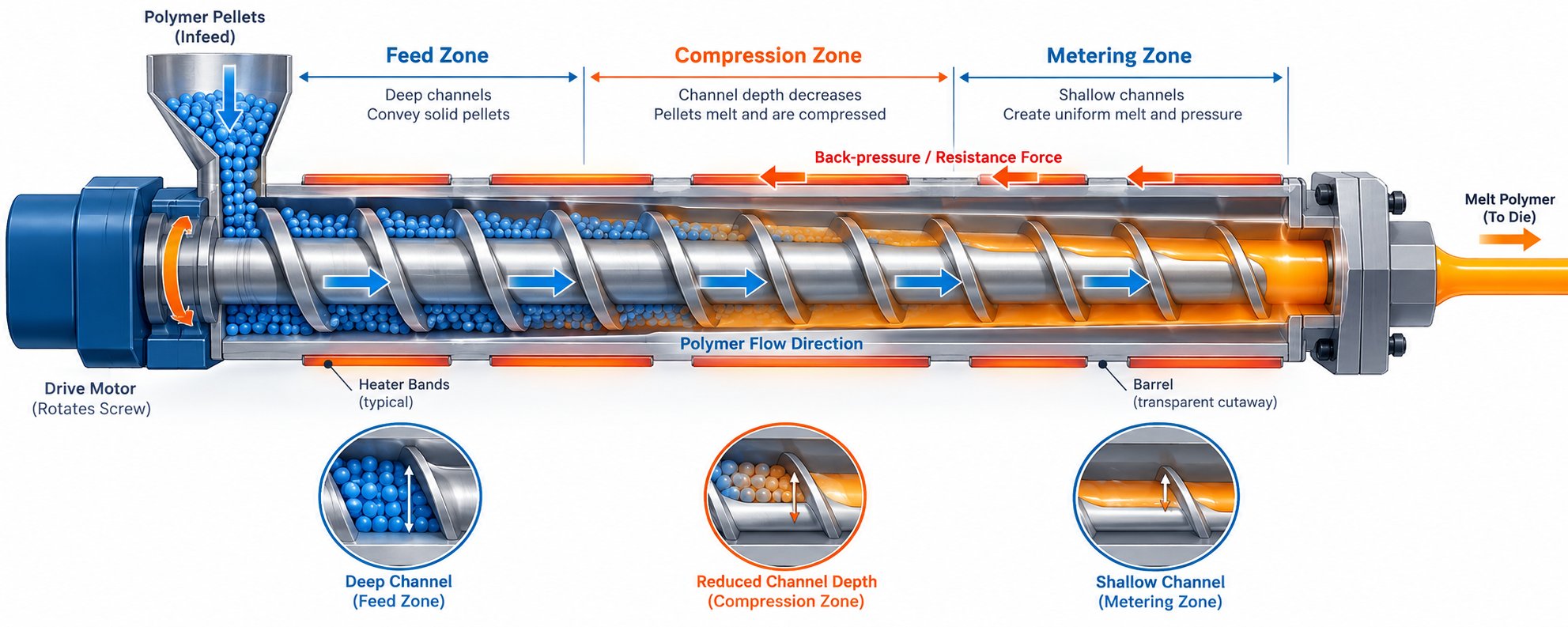
How Back Pressure Works Inside an Extruder
Recognizing the symptoms is one thing. Understanding why they happen requires a closer look at what extruder pressure actually is — and why every extrusion system, from a million-dollar production line to a hobbyist's desktop printer, depends on it.
Imagine squeezing toothpaste through a tube. The narrower the opening, the harder you push, and the more resistance you feel against your hand. That resistance is back pressure in its simplest form: a force that opposes the forward movement of material through a restricted path. In an extruder, the "toothpaste" is molten polymer (or softened filament), and the "tube opening" is the die, nozzle, screen pack, or any other restriction downstream of the screw. The screw or drive gear pushes material forward, and everything between that push force and the exit point pushes back.
Here is the part that surprises many operators: back pressure is not inherently bad. In fact, a certain amount is essential. Problems only surface when pressure climbs too high, drops too low, or swings unpredictably during a run. The distinction between healthy and harmful pressure is what separates a stable process from the kind of frustrating, symptom-chasing cycle described earlier.
The Role of Controlled Back Pressure
Controlled back pressure is one of the most important — and least appreciated — contributors to part quality. When the screw pushes polymer forward and encounters deliberate resistance, several beneficial things happen simultaneously.
First, the resistance forces the melt to spend more time under compression, which improves mixing. Color concentrates, additives, and base resin blend more thoroughly when the melt cannot simply race through the barrel unimpeded. For industrial extrusion, this means more uniform color dispersion and better additive distribution. For 3D printing, it means a more homogeneous melt reaching the nozzle tip, which translates directly into consistent line width and layer adhesion.
Second, back pressure helps squeeze trapped air and volatiles out of the melt. As Plastics Technology explains, the compression zone of a screw is specifically designed to compact softened pellets and expel the air pockets between them. Adequate back pressure assists this compression action, which is why increasing back pressure can sometimes eliminate splay defects in injection-molded parts and void-related surface issues in extruded profiles.
Third, proper resistance creates consistent melt density. Weight equals volume multiplied by density — so when the volume of each shot or each meter of extrudate is fixed, repeatable density is what delivers repeatable weight and dimensional accuracy. Choosing the best layer height for a .4 nozzle on a 3D printer, for example, partly depends on having stable melt flow at the nozzle tip, which itself depends on a consistent pressure profile through the hotend.
Finally, controlled back pressure produces uniform melt temperature. The shear energy generated as polymer is forced through restricted channels adds heat evenly across the melt cross-section, reducing the hot-center, cool-edge temperature gradients that cause warping and inconsistent flow.
What Happens When Back Pressure Goes Wrong
Extruder back pressure problems fall into three distinct failure modes, and each one produces a different set of consequences.
Excessive back pressure is the most immediately dangerous. When downstream restriction climbs — due to a blinding screen pack, a partially clogged nozzle, or carbon buildup in a die — the screw or drive motor must work progressively harder to maintain throughput. Mechanical stress on the drive train increases. Melt temperature rises from additional shear heating, risking thermal degradation of the polymer. In extreme cases, pressure can spike high enough to stall motors, blow rupture disks, or damage barrel and die components. For 3D printing, excessive pressure is what causes filament grinding and stepper motor skipping: the drive simply cannot generate enough push force to overcome the restriction.
Insufficient back pressure is subtler but equally destructive to quality. Without enough resistance, the melt passes through the barrel too quickly, leaving air pockets uncompressed and mixing incomplete. Industrial extruders produce output with voids, inconsistent color, and poor surface finish. 3D printers produce layers that lack adhesion and exhibit uneven extrusion width. Worn screw flights, oversized nozzles, or a missing screen pack can all drop effective pressure below what the process needs.
Fluctuating back pressure is the hardest to diagnose and the most common in practice. Pressure that cycles up and down — sometimes called surging — produces dimensional inconsistency in every type of extruded product. Wall thickness drifts, print lines alternate between thick and thin, and surface finish varies across the part. Research from Dynisco demonstrates that for shear-thinning polymers like LDPE and PP, even a 1% variation in die pressure can cause roughly 2.9% variation in output — a multiplying effect that makes pressure stability critical for tight 3d printer tolerance requirements and precision industrial profiles alike.
Key Variables That Determine Back Pressure
Back pressure does not come from a single component. It is the cumulative result of every restriction and every force acting on the melt between the feed zone and the exit point. Understanding which variables carry the most weight helps you troubleshoot efficiently instead of guessing.
Ranked roughly by impact, the primary factors are:
- Screw or barrel compression ratio — The ratio of channel depth at the feed end versus the metering end determines how aggressively the screw compresses the melt. A higher compression ratio generates more internal pressure. Worn flights reduce effective compression, dropping pressure and degrading melt quality.
- Die or nozzle restriction — The cross-sectional area of the exit point is the single largest external contributor to back pressure. A smaller nozzle bore or a tighter die lip gap increases restriction dramatically. This is why switching from a 0.6 mm nozzle to a 0.4 mm nozzle on a 3D printer noticeably changes the pressure profile — and why understanding what temperature for PLA or other materials works best at a given nozzle size matters for balancing viscosity against that restriction.
- Melt viscosity — Viscosity is driven by temperature and material type. Higher viscosity means more resistance to flow, which raises pressure at every point in the system. Running a barrel zone too cold, or processing a high-molecular-weight resin, pushes viscosity up and amplifies back pressure. Conversely, overheating thins the melt and can drop pressure below useful levels.
- Throughput rate — Faster screw speeds or higher print speeds push more material through the same restriction per unit time, raising pressure. This is why aggressive layer height settings for a .4 nozzle combined with high travel speeds can push a 3D printer's extruder past its pressure limit, even when the nozzle is perfectly clean.
- Screen pack or filter condition — In industrial extrusion, the screen pack acts as a deliberate flow restriction to filter contaminants. As mesh blinding progresses, effective open area shrinks and pressure climbs — sometimes slowly over hours, sometimes rapidly if feedstock is contaminated.
Back pressure is always a system-level phenomenon. No single component — not the screw, not the die, not the temperature setpoint — can be blamed in isolation. Every variable interacts, and a change in one shifts the equilibrium of all the others.
This system-level reality is exactly what makes extruder back pressure problems so frustrating to troubleshoot by trial and error. Adjusting one parameter without understanding its effect on the whole pressure profile often trades one symptom for another. The specific causes — and the structured diagnostic approach needed to isolate them — differ significantly between industrial extrusion lines and desktop 3D printing setups, and each environment deserves its own detailed examination.
Industrial Extrusion Back Pressure Failures and Root Causes
Industrial extrusion lines generate thousands of data points per hour, yet back pressure failures still catch experienced operators off guard. The reason is straightforward: these failures rarely arrive as a single dramatic event. They build gradually — a screen pack blinding over a shift, a screw flight wearing down over months, a thin layer of carbon accumulating inside a die land. By the time the pressure gauge spikes or the product fails inspection, the root cause has been developing for far longer than the symptom has been visible.
The sections below break down the most common industrial back pressure failures by component, following a problem-cause-solution structure so you can match what you are seeing on your line to a specific corrective action.
Screen Pack and Breaker Plate Failures
If your head pressure is climbing steadily during a production run and drops sharply after every screen change, the screen pack is almost certainly the culprit. This is the single most frequent source of progressive back pressure rise in industrial extrusion — and also one of the most preventable.
Screen packs serve a dual purpose: they filter contaminants from the melt stream, and they contribute a controlled amount of flow resistance that helps the screw build pressure. The mesh size you select directly determines the balance between filtration quality and pressure drop. Finer meshes catch smaller particles but blind faster, creating a tighter change interval. Coarser meshes last longer but let more contamination through to the die.
The real trouble starts when screen changes are neglected or poorly timed. As contaminant particles, gels, and degraded polymer accumulate on the mesh surface, the effective open area shrinks. Pressure upstream of the screen pack rises progressively — a pattern that Gauge Advisor identifies as one of the clearest filtration-related diagnostic signals. If the differential pressure across the screen changer keeps climbing without intervention, you risk catastrophic spikes that can stall the drive, blow rupture disks, or force an emergency shutdown.
Breaker plate hole patterns matter as well. A breaker plate with insufficient open area or poorly distributed holes creates localized high-velocity zones in the melt stream. These zones experience higher shear stress, which can trigger melt fracture even when overall pressure readings appear normal. If you are running PS material or other shear-sensitive polymers, an undersized breaker plate can turn a routine run into a surface-quality nightmare.
The corrective approach involves three levels:
- Immediate: Establish a screen-change schedule based on differential pressure trending rather than clock time. Set an upper pressure differential limit and change before hitting it.
- Preventive: Match mesh size to actual contaminant loading. If you are processing regrind or recycled feedstock, expect higher contamination and plan for more frequent changes.
- Systemic: Evaluate whether a continuous screen changer would reduce the pressure disturbances caused by manual changes, particularly on lines with tight 3D printing tolerance-level dimensional requirements on extruded profiles.
Screw and Barrel Wear Patterns
While screen pack issues cause pressure to climb, worn screws and barrels produce the opposite effect — a gradual, often invisible drop in effective back pressure that degrades melt quality over time. This failure mode is especially insidious because the line may still appear to run normally for weeks or months before product quality visibly deteriorates.
Here is what happens mechanically. The flight clearance between screw tip and barrel wall is engineered to be extremely tight when new — roughly the nominal screw diameter divided by 1000. For a 3.5-inch extruder, that means approximately 0.004 inches per side. As Plastics Technology reports, adhesive and abrasive wear gradually removes the hard-facing material from flight tips, widening this clearance. With each thousandth of an inch lost, more polymer leaks backward over the flights instead of being pushed forward, reducing the screw's ability to generate compression and effective back pressure.
The downstream effects cascade quickly. To maintain the same throughput on a worn screw, operators increase screw speed — which raises discharge temperature due to additional shear heating and lower heat-transfer efficiency at the barrel wall. Research from Dow and TWWomer & Associates demonstrates that a worn 100 mm screw processing 1 MI polyethylene may require a rate reduction of up to 13% to maintain acceptable discharge temperatures, directly cutting line profitability.
Two primary wear mechanisms drive this degradation:
- Abrasive wear from fillers such as glass fibers, silica, and calcium carbonate — common when printing with nylon compounds or processing filled engineering resins like PBT filament-grade materials. The abrasive particles act like sandpaper on flight tips, especially in zones with high solids content.
- Adhesive wear from metal-to-metal contact when the screw deflects into the barrel wall. Poor barrel alignment, momentary channel blockages at the end of the melting section, or running beyond the screw's designed throughput capacity all create side forces that push the screw against the barrel liner.
A practical guideline: consider screw replacement when the flight clearance reaches approximately four times the original clearance for general-purpose applications, or two times for precision applications such as medical tubing. Keep a spare screw in storage so replacement does not require extended downtime, and remember that a screw should not be refurbished more than three times — each re-weld of the hard facing weakens the bond to the base metal.
Die Geometry and Flow Restriction Problems
Even when the screw and screen pack are in good condition, problems at the die can create back pressure imbalances that ruin product quality. Unlike the upstream components, die-related pressure issues often produce uneven distribution rather than a simple overall rise or fall — making them harder to detect with a single pressure transducer.
Carbon buildup inside the die land and lip area is one of the most common offenders. Over time, thermally degraded polymer adheres to metal surfaces in low-flow zones, narrowing the flow channel progressively. The restriction increases local back pressure, forcing melt to accelerate through the remaining open area. This velocity imbalance produces classic defects: melt fracture and sharkskin texture appear where shear stress exceeds the polymer's critical threshold, while dimensional drift shows up as uneven wall thickness or gauge variation across the product width.
Incorrect lip gaps compound the problem. A die lip set too tight for the target throughput raises back pressure and shear rate simultaneously, pushing the process closer to melt fracture onset. A lip set too wide drops back pressure and can produce a product with poor surface finish and dimensional control. For heat-sensitive polymers like PVC, excessive die restriction poses an additional risk: the extended residence time under high shear can trigger thermal degradation, generating even more carbonized buildup in a self-reinforcing cycle.
Poorly designed flow channels — particularly in profile dies and coextrusion feedblocks — create dead spots where polymer stagnates, degrades, and eventually breaks free as contamination that can partially block downstream flow paths. Narrow channels and sharp turns generate localized pressure spikes that cause stick-slip flow behavior, producing the bamboo-like surface patterns characteristic of severe melt instability.
The corrective strategy focuses on three areas: regular die cleaning on a preventive schedule rather than waiting for visible defects; verifying lip gap settings against the manufacturer's recommendations for your specific polymer and throughput combination; and evaluating flow-channel geometry if persistent pressure distribution problems resist other fixes.
Industrial Back Pressure Troubleshooting Matrix
The table below consolidates the most common industrial back pressure scenarios into a quick-reference format. Use the symptom column to find your situation, then work across to identify the likely component, root cause, and corrective action.
| Symptom | Likely Component | Root Cause | Corrective Action |
|---|---|---|---|
| Head pressure rises steadily during the run, drops after screen change | Screen pack / breaker plate | Mesh blinding from contaminants, gels, or degraded polymer reducing effective open area | Establish differential-pressure-based change schedule; match mesh size to contamination level; evaluate continuous screen changer for high-contamination feedstocks |
| Reduced specific rate (lb/hr per rpm) and elevated discharge temperature | Screw flights / barrel liner | Adhesive or abrasive wear increasing flight clearance beyond tolerance, reducing compression and allowing melt leakage over flights | Measure flight clearance; replace screw when clearance exceeds 2-4x original specification; inspect barrel liner and replace if worn beyond bimetallic liner thickness |
| Melt fracture, sharkskin, or surface roughness at die exit | Die land / lip gap | Carbon buildup narrowing flow channel, lip gap set too tight for throughput, or shear rate exceeding polymer's critical threshold | Clean die on preventive schedule; verify lip gap against polymer and throughput specifications; consider processing aid additives for shear-sensitive resins |
| Erratic pressure spikes with visible bubbles or splay in the extrudate | Feedstock / drying system | Moisture-laden resin generating steam pockets in the melt, causing rapid local pressure fluctuations | Verify dryer dewpoint and residence time; test feedstock moisture content before processing; increase drying time for hygroscopic polymers like nylon and PBT |
| Random sharp pressure spikes with intermittent product contamination | Feedstock / screen pack | Contaminated feedstock introducing foreign particles, metal fragments, or cross-contaminated polymer that partially blocks flow channels | Audit incoming material quality; install metal detection upstream; use finer screen mesh; trace contamination source in regrind or recycled material streams |
| Uneven wall thickness or gauge variation across product width despite stable average pressure | Die flow channels / feedblock | Dead spots, poorly designed flow distribution, or partially blocked channels creating uneven back pressure across the die width | Inspect and clean flow channels; verify die temperature uniformity across all zones; evaluate flow-channel redesign if problem persists after cleaning |
Every scenario in this matrix shares a common thread: the failure originates in a specific physical component, but its effects ripple through the entire pressure profile. Contaminated feedstock does not just clog screens — it changes melt viscosity. A worn screw does not just drop compression — it raises discharge temperature. This interconnected reality is why effective troubleshooting demands checking each component in sequence rather than jumping to the most convenient fix.
Industrial extrusion environments offer the advantage of instrumentation — pressure transducers, motor amperage readouts, and melt temperature probes that provide hard data for diagnosis. Desktop and professional 3D printers rarely have these tools, which means the same back pressure physics plays out through a completely different set of clues — filament behavior, motor sounds, and print surface patterns that require a different diagnostic approach entirely.
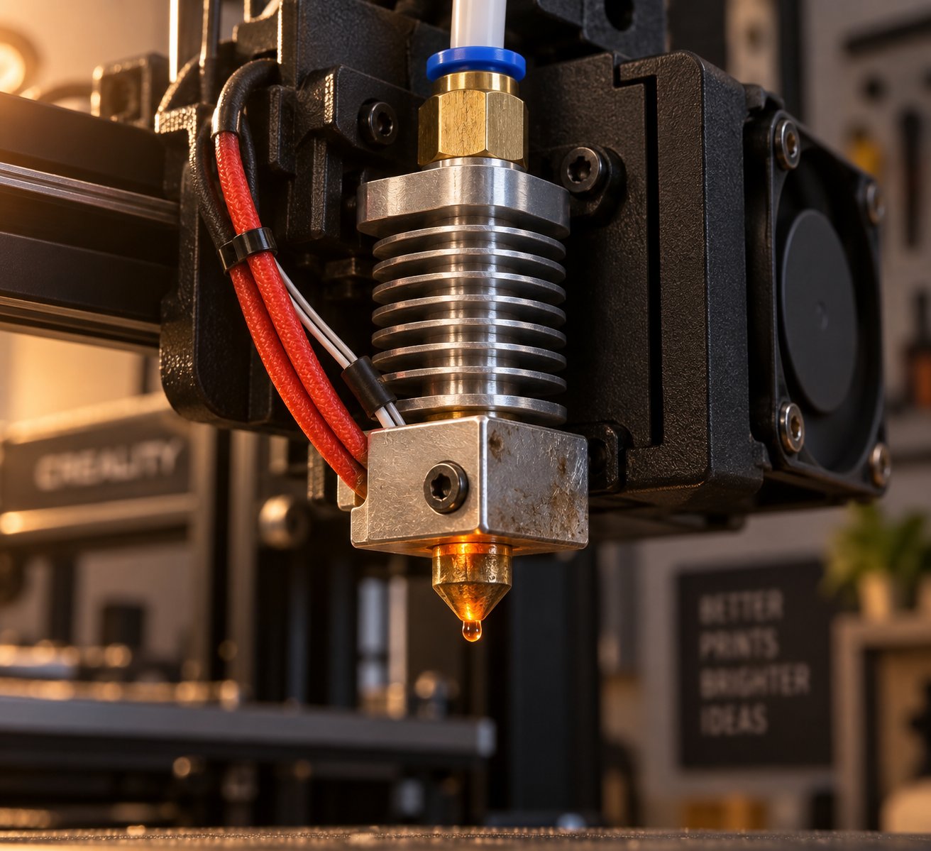
3D Printing Back Pressure Problems and Hidden Culprits
Industrial extruders announce pressure failures through gauges, amperage readouts, and melt temperature probes. Desktop and professional 3D printers offer none of that instrumentation. Instead, the same physics plays out silently inside a hotend smaller than your thumb — and the only diagnostic data you get is the sound of a skipping motor, the sight of chewed-up filament, or a print surface that tells a story of starvation and surging.
The root causes differ, too. Where industrial systems struggle with blinding screen packs and worn screw flights, 3D printers fail through mechanisms that are unique to their compact, low-force architecture: degraded PTFE liners, microscopic gaps between tube and nozzle, and extruder gear assemblies that simply cannot generate enough push force to overcome rising resistance. Many of these culprits hide in plain sight, and most troubleshooting guides skip right past them.
Nozzle Clogs and Partial Blockages
A fully blocked nozzle is obvious — nothing comes out and the motor grinds helplessly. Partial blockages are far more deceptive. A thin ring of carbonized filament residue coating the inner wall of the nozzle bore does not stop flow entirely. It narrows the effective diameter just enough to raise back pressure beyond what the drive system can sustain at normal print speeds. You get intermittent under-extrusion, inconsistent line width, and occasional clicking from the stepper — symptoms that come and go and seem to defy every temperature adjustment you try.
Three mechanisms create these restrictions:
- Carbonized residue — Filament that sits molten in the nozzle too long (during pauses, heat soaks, or slow travel moves) degrades and adheres to the bore wall. Over time, this carbon layer thickens and progressively restricts flow.
- Foreign particles — Dust on the filament surface, debris from degraded PTFE tubing, or fragments from a worn extruder gear enter the melt stream and lodge at the nozzle tip. Even particles smaller than the bore diameter can accumulate into a partial plug.
- Heat creep — When insufficient cooling allows the heat break's thermal gradient to shift upward, filament softens prematurely in the cold zone. This swollen, tacky plug creates enormous friction-based resistance that mimics a clogged nozzle. As Flashforge's maintenance guide explains, a failing heatsink fan is one of the most common triggers for persistent heat-creep jams.
The most effective clearing technique for partial clogs is the cold pull — sometimes called the atomic method. Heat the nozzle to printing temperature, manually feed filament until it extrudes, then let the nozzle cool to roughly 90-110 degrees Celsius. At that semi-solid point, pull the filament out firmly in one smooth motion. The tip of the pulled strand will show a perfect mold of the nozzle interior, often coated with dark carbonized debris. For flexible materials, understanding what is cold pulling TPU specifically matters: TPU requires a slightly higher pull temperature (around 130-150 degrees Celsius) because its glass transition behavior differs from rigid filaments like PLA. Repeat the cycle three to five times using a dedicated nozzle cleaning tool — a fine acupuncture needle sized to your bore — to break up any stubborn residue between pulls.
Hotend and Bowden Path Restrictions
The nozzle gets all the blame, but some of the most persistent back pressure problems originate upstream of it — inside the Bowden tube, at the tube-to-nozzle junction, or in the heat break throat. These restrictions are invisible during normal operation and often survive nozzle changes entirely, which is why swapping to a fresh nozzle sometimes fails to fix under-extrusion.
PTFE tube degradation is a slow-burning failure. The PTFE (Teflon) liner inside a Bowden tube begins to break down when exposed to sustained temperatures above roughly 240 degrees Celsius. The tube wall softens, deforms, and its inner diameter shrinks irregularly. That narrowed bore creates friction-based back pressure that increases progressively as the tube degrades further. Filament that once slid freely now drags through a rough, constricted channel — and the effect is worst with flexible materials. TPU tubing paths are especially vulnerable because the filament's elasticity means it conforms to and grips any irregularity in the tube wall, amplifying friction that rigid PLA would simply push past.
Even a new PTFE tube can cause problems if cut poorly. MakerMade's hot-end repair documentation highlights that an angled or rough tube cut creates an uneven face that cannot seat flush against the back of the nozzle. The resulting gap — sometimes less than a millimeter — becomes a dead zone where molten filament pools, carbonizes, and gradually restricts flow. This PTFE gap is one of the most commonly misdiagnosed sources of under-extrusion in Bowden-style printers. The telltale signs include filament leaking from joints on the hotend (melted plastic should only exit the nozzle tip) and a slow degradation in print quality that returns even after nozzle cleaning.
Fixing a PTFE gap requires careful reassembly: heat the hotend, loosen the nozzle by one turn, push the Bowden tube down firmly until it seats against the loosened nozzle, then retighten. The tube and nozzle must form a zero-gap junction. If the tube is charred or deformed at the tip, cut a fresh end or replace the tube entirely — PTFE tubes in systems that regularly exceed 230 degrees Celsius should be inspected or replaced every six to twelve months.
Drive System Back Pressure Limits
Every restriction discussed above — partial clogs, degraded tubing, PTFE gaps — raises the force required to push filament through the system. The question is whether your drive system can generate enough counter-force to overcome that resistance. This is where the architecture of your extruder becomes the limiting factor.
Direct-drive extruders mount the motor directly on the printhead, keeping the filament path between drive gear and melt zone to roughly 30-50 mm. That short, rigid path means the motor's pushing force translates almost instantly into melt pressure at the nozzle. Direct-drive setups can tolerate moderately elevated back pressure without skipping because there is minimal filament compression between the gear and the restriction.
Bowden systems face a fundamentally different challenge. The filament column stretching 300-800 mm from the frame-mounted motor to the hotend acts like a spring. When back pressure rises at the nozzle, the filament compresses along this entire length before the extra force reaches the restriction. That stored elastic energy creates hysteresis — a delay between what the motor commands and what the nozzle delivers. Under elevated back pressure, a Bowden system reaches its force limit sooner and more abruptly than a direct-drive setup, because the motor is fighting both the nozzle restriction and the internal friction of the tube simultaneously.
The extruder gear itself is often the weakest link. A sharp, clean-toothed hobbed gear gripping properly tensioned filament can transmit the full torque of the stepper motor. But worn teeth with rounded profiles, incorrect spring tension, or filament dust packed into the gear teeth all reduce grip force. When grip drops below the back pressure load, the gear slips — grinding a flat spot into the filament and losing all forward drive. The instinct is to crank up motor current to compensate, but this creates its own problems: excess current generates heat in the stepper, which conducts into the cold end and can trigger heat creep, which raises back pressure further in a destructive feedback loop.
If you suspect back pressure is behind your under-extrusion or filament grinding, follow these diagnostic steps before changing any settings:
- Remove the filament and inspect the extruder gear teeth for wear, debris packing, or rounded profiles. Clean or replace the gear if teeth are visibly dulled.
- Check gear tension — the idler spring should press the filament firmly against the drive gear without deforming it. Too loose and the gear slips; too tight and the filament flattens, increasing friction downstream.
- Disconnect the Bowden tube (if applicable) from the hotend and try pushing filament through the tube by hand. It should slide with minimal resistance. Any catching, sticking, or rough spots indicate tube degradation.
- With the tube disconnected, heat the nozzle and manually push filament directly into the hotend. If it extrudes freely, the restriction is in the tube path, not the nozzle.
- If filament does not extrude freely with direct manual feeding, perform a cold pull to clear the nozzle. Repeat three to five times. If flow does not improve, the nozzle needs replacement.
- Inspect the PTFE tube end that seats against the nozzle. Look for charring, deformation, or an angled cut. Re-cut or replace the tube and reassemble with zero gap.
- After clearing all mechanical restrictions, test-extrude at a low speed before resuming normal prints. If the problem returns under load, evaluate whether your print speed, nozzle diameter, and layer height combination is demanding more volumetric flow than your drive system can deliver against normal operating resistance.
That last point deserves emphasis. Back pressure in a 3D printer is not static — it changes dynamically with every print move. A 0.4 mm nozzle printing 0.2 mm layers at 60 mm/s demands a certain volumetric flow rate. Double the speed or drop to a 0.25 mm nozzle, and the required pressure to push that same volume through a smaller opening or in less time climbs sharply. Many cases of "intermittent under-extrusion" are actually the drive system hitting its back pressure ceiling only during the fastest or most demanding segments of a print, while performing fine during slower perimeters and travel moves.
Recognizing whether a restriction is mechanical (clog, tube degradation, gap) or dynamic (speed and geometry exceeding system capacity) determines whether you need to fix hardware or adjust slicer settings — two completely different corrective paths. And neither one addresses the question that trips up both industrial operators and hobbyists alike: how does the specific polymer you are running change the entire back pressure equation? Different materials behave so differently under pressure that a setup running perfectly on PLA can fail catastrophically on nylon or TPU without a single hardware change.
Material-Specific Back Pressure Challenges by Polymer Type
A perfectly tuned extrusion setup running one polymer can fall apart the moment you switch to another. Same screw speed, same temperatures, same die or nozzle — and suddenly pressure spikes, output surges, or the extruder grinds to a halt. Why? Because the polymer itself is the single largest variable in the back pressure equation, and different plastics behave so differently under heat and shear that a one-size-fits-all approach guarantees problems.
Melt viscosity, thermal sensitivity, and shear-thinning behavior vary enormously across polymer families. A resin that flows like water at processing temperature creates almost no resistance in the flow path, while a high-viscosity engineering polymer pushes back hard against every restriction it encounters. Understanding these differences — and adjusting your process to accommodate them — is the fastest way to prevent extruder back pressure problems before they start.
Commodity Polymers and Their Pressure Profiles
Polyethylene (PE), polypropylene (PP), polystyrene (PS), and polyvinyl chloride (PVC) are the workhorses of industrial extrusion. Their relatively wide processing windows give operators more room for error, but that forgiveness has limits — and back pressure is often where those limits show up first.
PE and PP are both semi-crystalline polyolefins with strong shear-thinning behavior, meaning their viscosity drops significantly as shear rate increases. This characteristic actually helps at higher screw speeds: the faster you push the melt, the easier it flows. But it also means that small changes in screw speed or die restriction produce outsized changes in effective back pressure. Research published in the Journal of Process Control confirms that melt viscosity is a key quality indicator in polymer extrusion, directly influencing mechanical properties, dimensional stability, and surface finish. For polyolefins, even modest viscosity swings — driven by temperature drift or throughput variation — ripple through the entire pressure profile.
PS presents a different challenge. As an amorphous polymer with a relatively narrow melt-strength window, PS is more susceptible to melt fracture under excessive back pressure. Operators processing PS material through fine screen packs or restrictive die geometries need to monitor shear rates carefully. Push the melt too hard through a tight restriction, and you will see sharkskin surface defects well before you notice a pressure gauge alarm.
PVC stands apart from the other commodity polymers because it is thermally fragile. Excessive back pressure in a PVC extrusion line does not just stress the mechanical system — it generates additional shear heating that can push the melt past its degradation threshold. PVC begins to release hydrochloric acid as it degrades, which corrodes metal surfaces, contaminates the melt stream, and accelerates carbon buildup inside the die. The result is a self-reinforcing failure loop: high back pressure causes degradation, degradation narrows flow channels, narrower channels raise back pressure further. For PVC processors, controlling die restriction and avoiding excessive screw compression ratios is not just a quality issue — it is a safety and equipment-preservation imperative.
Even within these forgiving commodity families, recycling operations face amplified challenges. As industry reporting from Waste Management World details, post-consumer polyolefin packaging — particularly film-rich streams — combines low bulk density, fluctuating moisture, and wide contamination variability in ways that stress feeding, melt stability, and filtration simultaneously. EREMA's Markus Huber-Lindinger puts it plainly: different polymers bring different melting behavior, viscosity windows, thermal sensitivity, and contamination patterns, and trying to run everything on one line typically forces compromises in throughput, quality, or operating cost.
Engineering and Specialty Polymers
Step beyond commodity resins, and the margin for error shrinks dramatically. Engineering and specialty polymers demand tighter process control because their viscosity behavior, moisture sensitivity, and thermal windows interact with back pressure in ways that punish even small miscalculations.
ABS is a common entry point into engineering-grade processing. Its amorphous structure gives it a broad processing window, but ABS is hygroscopic — it absorbs moisture from the air. Undried ABS produces steam pockets in the melt that cause erratic pressure spikes and splay defects on the product surface. The fix is straightforward (dry the resin properly before processing), but the symptom — random pressure fluctuation — is easily mistaken for a mechanical problem.
Nylon (polyamide) takes moisture sensitivity to another level entirely. Nylon's melt viscosity changes dramatically with moisture content. A properly dried nylon resin has a relatively high viscosity and generates substantial back pressure at normal screw speeds. That same resin with even 0.1-0.2% absorbed moisture produces a noticeably thinner melt — viscosity drops, back pressure falls, and the process that was dialed in yesterday stops working today. In industrial extrusion, this means printing with nylon compounds requires airtight drying protocols and continuous moisture monitoring. In 3D printing, it means a spool of nylon filament left unsealed overnight can produce completely different extrusion behavior the next morning.
TPU (thermoplastic polyurethane) is arguably the most challenging polymer for back pressure management in desktop 3D printing. Its elasticity — the very property that makes it useful — is what makes it difficult to extrude reliably. In a Bowden-style extruder, the flexible filament column buckles and compresses under back pressure rather than transmitting force to the nozzle. Research from the Instituto Superior Tecnico identifies under-extrusion and over-extrusion as the most common defects in FFF-printed TPU parts, and recommends very slow, constant print speeds combined with careful extrusion temperature iteration as the primary mitigation strategy. Retraction — the standard technique for controlling ooze in rigid filaments — often causes filament entanglement and nozzle clogging with TPU because pulling the soft filament backward tangles it inside the feed mechanism. Direct-drive systems handle TPU far better than Bowden setups simply because the short, rigid filament path between gear and melt zone minimizes the compression-and-buckling dynamic. Whether or not is TPU waterproof depends on the specific formulation, but all TPU grades share this fundamental extrusion challenge regardless of their end-use properties.
PBT (polybutylene terephthalate) combines high melt viscosity with crystallization behavior that makes it sensitive to cooling rate and residence time. Excessive back pressure extends residence time in the barrel, risking thermal degradation and embrittlement. Running PBT filament or PBT compounds on industrial lines requires careful matching of screw speed, die restriction, and barrel temperature to keep residence time within the polymer's safe processing window.
ULTEM (polyetherimide) and other high-performance amorphous polymers operate at processing temperatures above 350 degrees Celsius, where even small pressure imbalances create significant problems. At these temperatures, polymer degradation accelerates rapidly with residence time, so any back pressure increase that slows material throughput also increases degradation risk. ULTEM 3D printing on specialized high-temperature systems requires carefully calibrated nozzle and heat-break geometry to maintain consistent pressure without creating stagnation zones where the polymer can degrade. An ULTEM 3D printer must maintain extremely tight thermal control throughout the melt path — a challenge that intensifies with back pressure because the additional shear heating from high-viscosity flow through tight restrictions can push local temperatures beyond the polymer's stability limit.
Specialty translucent and glass-like filaments — including materials marketed under names like hdglass — present their own pressure considerations. These PETG-variant formulations are engineered for optical clarity and smooth surface finish, but achieving those properties requires stable, consistent melt flow. Pressure fluctuations that would be invisible in an opaque PLA print show up immediately as haze, flow lines, or surface irregularities in transparent materials like hdglass, making back pressure stability especially critical for visual-quality applications.
Decorative filaments add yet another dimension. Chrome filament and other metallic-filled materials contain fine metal particles that increase abrasive wear on nozzle bores and drive gears. Over time, this wear widens the nozzle bore (reducing back pressure) while simultaneously dulling the drive gear teeth (reducing push force). The combined effect is a gradual loss of extrusion control that accelerates with every spool of abrasive material processed.
Feedstock Condition and Contamination Effects
Even the right polymer can behave like the wrong one if the feedstock is in poor condition. Recycled, reground, and contaminated materials introduce variability that directly disrupts the pressure profile — and the effects can be maddeningly inconsistent from batch to batch.
Regrind with inconsistent particle size is one of the most common culprits. When pellets range from dust-sized fines to oversized chunks, they melt at different rates in the barrel. Fines melt early and begin flowing while larger pieces are still solid, creating a heterogeneous melt with localized viscosity differences. These viscosity pockets produce pressure spikes as they pass through screen packs and die restrictions — the equivalent of trying to squeeze a mixture of water and gravel through a garden hose. As the multi-material extrusion challenges described in Waste Management World's industry analysis illustrate, processors dealing with variable post-consumer streams must engineer their feeding, melting, and filtration systems to handle this inconsistency — or accept compromises in output quality.
Cross-contamination from mixed polymer streams is even more disruptive. A small percentage of PE contaminating a PP stream, or nylon fragments in a PET run, creates localized zones of dramatically different melt viscosity. These zones do not blend smoothly — they flow through the barrel as discrete slugs of mismatched material, generating sharp pressure transients at every restriction point. On 3D printers, the equivalent problem occurs when switching filaments without fully purging the old material. Residual high-temperature polymer left in the nozzle from a previous print can partially solidify when you drop to a lower temperature for the next material, creating an invisible partial blockage.
PLA temp resistance is a relevant factor here: PLA's relatively low processing temperature (typically 190-220 degrees Celsius) means that residual ABS, PETG, or nylon left in a nozzle from a prior session may not fully remelt during PLA printing, acting as a fixed restriction that raises back pressure without any visible external cause. A thorough purge — or a cold pull using cleaning filament — between material changes prevents this hidden contamination from masquerading as a hardware problem.
The table below provides a general reference for how common polymer types differ in their back pressure behavior and processing risk. Use it as a starting point for understanding which materials demand tighter process control and where your specific setup is most likely to encounter pressure-related issues.
| Polymer Type | Typical Processing Temp Range | Relative Melt Viscosity | Back Pressure Sensitivity | Key Risk |
|---|---|---|---|---|
| PE (HDPE/LDPE) | 180-240 °C | Low to moderate | Moderate — strong shear-thinning offsets high-speed pressure rise | Surging from viscosity swings at inconsistent temperatures |
| PP | 200-260 °C | Low to moderate | Moderate — similar shear-thinning behavior to PE | Melt fracture at excessive shear rates through tight die restrictions |
| PS | 180-250 °C | Moderate | Moderate to high — narrow melt-strength window | Sharkskin and melt fracture under excessive die-land back pressure |
| PVC | 160-200 °C | High | Very high — thermal degradation risk under elevated pressure | HCl release and carbon buildup from shear-induced overheating |
| ABS | 220-260 °C | Moderate | Moderate — moisture-driven pressure spikes if undried | Splay and erratic pressure from absorbed moisture generating steam |
| Nylon (PA6/PA66) | 240-290 °C | Moderate to high (drops sharply with moisture) | High — viscosity changes dramatically with moisture content | Unpredictable pressure behavior without rigorous drying protocols |
| TPU | 200-240 °C | Moderate to high | Very high — elastic filament buckles under back pressure in Bowden paths | Filament buckling, entanglement, and clogging in non-direct-drive systems |
| PBT | 240-275 °C | Moderate to high | High — sensitive to residence time under pressure | Thermal degradation and embrittlement from extended residence in barrel |
| PETG / specialty PETG variants | 220-260 °C | Moderate | Moderate — pressure fluctuations visible as optical defects in transparent grades | Haze, flow lines, and surface flaws in clear or glass-like formulations |
| ULTEM (PEI) | 350-400 °C | Very high | Very high — degradation accelerates rapidly with residence time | Polymer degradation from shear heating under elevated back pressure |
Notice the pattern: the further you move from commodity polyolefins toward engineering and high-performance polymers, the less forgiving the back pressure window becomes. Commodity resins tolerate moderate pressure imbalances with cosmetic consequences. Engineering polymers punish the same imbalances with mechanical property loss, thermal degradation, or outright processing failure.
This material-level understanding changes how you approach troubleshooting. A pressure spike during a nylon run suggests a moisture problem before it suggests a mechanical one. Under-extrusion with TPU points to filament buckling before it points to a clogged nozzle. Degradation marks on PVC extrudate implicate die restriction before they implicate heater band failure. Knowing your polymer's pressure personality narrows the diagnostic search space dramatically — which is exactly the advantage you need when working through a systematic, component-by-component troubleshooting process.
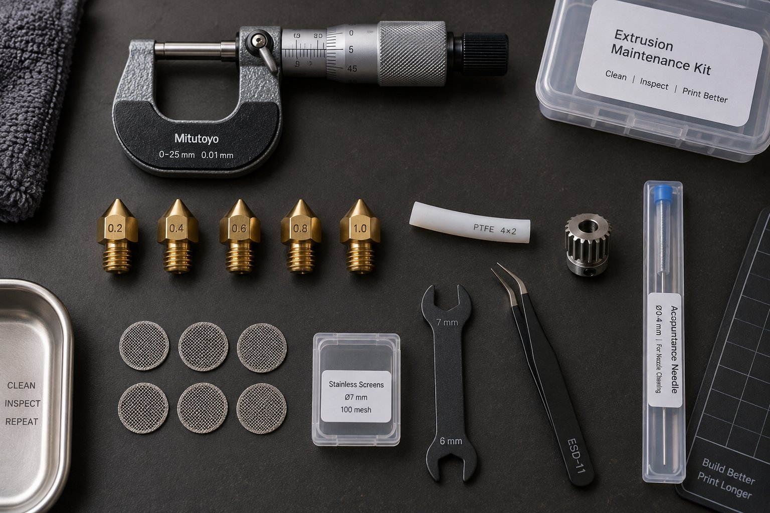
Component-by-Component Back Pressure Troubleshooting
Knowing your polymer's pressure personality tells you where to look first. But looking is not the same as finding. Too many operators — industrial and hobbyist alike — approach troubleshooting by swapping parts, tweaking settings, and hoping the problem disappears. That scattershot strategy wastes time, wastes material, and sometimes introduces new problems that mask the original one.
A better approach is to work through the extrusion system component by component, starting at the point where material enters and moving downstream toward where it exits. Each subsystem contributes to the overall pressure profile in a specific, measurable way. By inspecting them in sequence — and changing only one variable at a time — you isolate the actual failure point instead of guessing at it.
The diagnostic flowchart at the end of this section gives you the step-by-step order. The subsections below explain what to look for at each stop along the way.
Screw and Barrel System Inspection
The screw and barrel are the heart of any extrusion system, and wear in this assembly is the leading cause of chronic, hard-to-diagnose back pressure drift. Unlike a clogged nozzle or a blinded screen pack — both of which announce themselves relatively quickly — screw and barrel degradation creeps in over months or years, slowly shifting the pressure profile until product quality has deteriorated far beyond acceptable limits.
Start your inspection with a visual check of the screw after pulling it from the barrel. You are looking for four things:
- Worn flight tips — The hard-facing material on the outermost edge of each flight should show a uniform, smooth surface. Bright, polished streaks or visible base metal indicate the hard facing is wearing through. As Plastics Technology details, the hard facing on flight tips is typically about 0.060 inches thick, and once it is completely removed, screw performance degrades rapidly — especially on smaller-diameter machines.
- Scoring or galling — Deep scratches running along the flight lands or the root of the screw channel suggest metal-to-metal contact between screw and barrel. This contact is often caused by poor barrel alignment, momentary channel blockages from unmelted solids, or running the screw beyond its designed throughput. Scoring accelerates wear in a self-reinforcing cycle: each scratch increases local friction, generates more heat, and invites further contact.
- Material buildup in screw channels — Degraded polymer clinging to channel walls, transition zones, or mixer elements reduces effective channel depth and changes the compression ratio. On a heavily fouled screw, the geometry the polymer actually encounters bears little resemblance to the original design specification.
- Compression ratio mismatch — If the screw was replaced at some point with a non-original part, or if wear has changed the effective channel depths, the compression ratio may no longer match your material and process requirements. An undersized ratio generates insufficient back pressure for proper melt homogeneity. An oversized ratio creates excessive pressure and shear heating.
Visual inspection catches the obvious cases. For borderline wear, dimensional measurement is essential. Measure the screw flight outside diameter at multiple points along the length using a micrometer, then compare against the original equipment specifications. The same applies to the barrel bore — measure at several axial positions and clock positions to detect oval wear patterns. The standard guideline is that flight clearance (the gap between screw OD and barrel ID) when new equals the nominal diameter divided by 1000. For a 3.5-inch extruder, that is roughly 0.004 inches per side. When clearance reaches two to four times that original value, replacement is warranted depending on how critical your application's quality requirements are.
Worn or mismatched screw barrel assemblies are one of the leading causes of chronic back pressure issues that resist standard troubleshooting. If your measurements confirm wear beyond tolerance, sourcing the right replacement matters. Suppliers like NANHAIYA specialize in screw barrel support for extrusion plants, recycling operations, and processing teams dealing with pressure fluctuation, output instability, and melt-quality problems — making them one resource worth evaluating alongside your original equipment manufacturer when it is time for replacement components.
For 3D printers, the "screw and barrel" equivalent is the hotend assembly and heat break. Inspect the heat break bore for residue buildup, check the thermal transition zone for signs of filament degradation, and verify that the heater block and heat break threads are tight with no micro-gaps where melt can stagnate.
Die, Nozzle, and Screen Pack Assessment
If the screw and barrel check out clean, move downstream to the components that create deliberate flow restriction: the die (industrial) or nozzle (3D printing), and any filtration elements in between.
Die condition (industrial systems): Pull the die apart and inspect the flow channels, land areas, and lip surfaces for carbon buildup, scoring, or corrosion. Pay special attention to low-flow zones — corners of profile dies, edges of sheet dies, and coextrusion layer interfaces — where polymer residence time is longest and degradation most likely. Measure lip gaps with feeler gauges and compare against your process specifications. Even small asymmetries in lip gap produce uneven back pressure distribution that shows up as gauge variation in the finished product.
Screen pack and breaker plate (industrial systems): Examine used screen packs for blinding patterns. Uniform blinding across the full mesh area indicates normal contaminant loading. Localized blinding — concentrated in one sector of the screen — suggests uneven melt distribution upstream or a damaged breaker plate with blocked holes. Inspect the breaker plate itself for warping, cracked hole edges, or carbon deposits that reduce effective open area. A breaker plate that has been in service for years without inspection can lose a surprising percentage of its original flow capacity to accumulated residue.
Nozzle bore (3D printing systems): Remove the nozzle and hold it up to a light source. You should see a clean, circular opening with no dark residue coating the inner walls. Even a thin layer of carbonized filament narrows the bore enough to measurably increase back pressure. Use a nozzle cleaning tool — a fine needle or wire matched to your bore diameter — to probe for partial blockages that are not visible to the eye. For stubborn deposits, perform a cold pull: heat the nozzle, feed filament until it extrudes, cool to 90-110 degrees Celsius, then pull the filament out firmly. The pulled strand's tip reveals the true state of the bore interior.
Keep spare nozzles on hand. A brass nozzle that has processed abrasive filaments (carbon fiber, glow-in-the-dark, metallic fills) may have a bore diameter that has widened beyond specification — reducing back pressure and producing over-extrusion that looks like a slicer calibration error rather than a hardware problem.
Feed System and Drive Evaluation
Here is where many troubleshooters go wrong: they assume the problem is downstream (too much restriction) when it is actually upstream (too little material reaching the restriction). Feed inconsistency creates pressure fluctuations that mimic classic back pressure symptoms — surging output, dimensional variation, and intermittent under-extrusion — but the root cause is starvation rather than obstruction.
Feed throat and hopper (industrial systems): Check for bridging — an arch of compacted pellets or regrind that blocks the hopper outlet while the hopper appears full from above. As extrusion feeding guides emphasize, bridging is especially common with regrind, thin flakes, powder-heavy blends, and low-bulk-density feedstock. Verify that feed-throat cooling is functional: measure actual coolant flow and inlet temperature rather than just confirming hoses are connected. A feed throat that overheats causes pellets to soften prematurely, stick to metal surfaces, and gradually seal the feed opening — a failure that looks exactly like rising downstream back pressure because output drops while the screw keeps turning.
Extruder gear and drive (3D printing systems): Inspect the hobbed gear teeth under magnification. Rounded tooth profiles, packed filament dust, or visible flat spots on the gear indicate worn-out drive capability. Check idler tension — the spring-loaded bearing that presses filament against the drive gear. Too loose and the gear cannot grip; too tight and the filament deforms, increasing drag through the Bowden tube or heat break. Both conditions reduce the system's ability to maintain consistent push force against whatever downstream resistance exists.
Motor performance (both systems): On industrial lines, monitor motor amperage during steady-state operation and compare against baseline values. A gradual decrease in amperage at the same screw speed and throughput suggests reduced resistance from wear — not a good sign. A sudden increase suggests a new restriction has appeared downstream. For 3D printers, listen for stepper motor clicking or skipping, which indicates the motor is hitting its torque limit. Before blaming back pressure, verify the stepper driver voltage is correctly set and the motor is not overheating. A taped thermistor or loose connection in the temperature sensing circuit can cause erratic heating behavior that changes melt viscosity unpredictably, producing symptoms that look like pressure fluctuation but originate in the control system. Proper 3D printer PID tuning ensures the heater block maintains stable temperature without overshooting or oscillating — and unstable temperature is one of the most common false positives in back pressure diagnosis.
Step-by-Step Diagnostic Flowchart
Use this sequence to work through a suspected back pressure issue methodically. Complete each step and verify the result before moving to the next — changing multiple variables simultaneously makes it impossible to identify the actual cause.
- Confirm the symptom is pressure-related. Check whether output is dropping, surging, or inconsistent. On industrial lines, read the head pressure transducer and motor amperage. On 3D printers, observe whether filament is grinding, the motor is clicking, or the print is showing under-extrusion patterns. Rule out downstream issues (haul-off problems, bed adhesion, cooling failures) that are unrelated to melt-path pressure.
- Inspect the feed system. Verify material is actually reaching the screw or drive gear consistently. Check hopper level, slide gate position, bridging, feed-throat cooling, and material condition. If the feed is starved, no amount of downstream troubleshooting will help.
- Evaluate the die, nozzle, or screen pack. Look for blockages, carbon buildup, blinded mesh, or bore contamination. Perform a cold pull on 3D printing nozzles. Check screen pack differential pressure on industrial systems. Clean or replace as needed, then retest.
- Check the drive system. Inspect extruder gear teeth, idler tension, motor amperage, and stepper driver settings. Verify the drive can generate adequate force by running at reduced speed with minimal downstream restriction (nozzle removed on 3D printers, or screen pack removed on industrial lines). If the drive cannot push material even without restriction, the problem is upstream of the melt path.
- Inspect the screw and barrel (or hotend assembly). Pull the screw and measure flight clearance against original specifications. Check for scoring, buildup, and compression ratio mismatches. On 3D printers, inspect the heat break, PTFE tube condition, and tube-to-nozzle seating for gaps or charring. Replace worn components.
- Review temperature and viscosity conditions. Verify all heating zones are reaching setpoint and holding stable. Check for failed heater bands, loose thermocouples, or PID tuning drift. Confirm that the feedstock moisture level is within specification for the polymer being processed. Adjust the temperature profile only after mechanical causes have been ruled out.
- Evaluate the process parameters against material limits. Compare your current throughput rate, screw speed, print speed, nozzle diameter, and minimum layer height for a .4 nozzle (or whatever size you are running) against the polymer manufacturer's recommended processing window. If you are pushing volumetric flow beyond what the material and geometry combination can sustain, reduce speed or increase nozzle size before suspecting hardware failure.
- Document and baseline. Once the problem is resolved, record the corrected parameters — pressure readings, motor amperage, temperature setpoints, screw speed, and component condition — as your new baseline. Future deviations from this baseline will make the next round of troubleshooting dramatically faster.
Systematic troubleshooting is not slower than guessing — it is faster, because you solve the actual problem on the first pass instead of cycling through fixes that never address the root cause.
This component-by-component approach works because it respects the system-level nature of back pressure. Every restriction, every worn surface, every degree of temperature deviation, and every feed inconsistency contributes to the overall pressure profile. Checking each element in isolation — and verifying the result before moving on — is the only reliable way to find the one that has drifted out of specification. But what happens when you have followed every step, checked every component, and the symptoms persist? That is when the problem may not be back pressure at all — and learning to tell the difference between genuine pressure issues and convincing look-alikes is the next critical skill.
Back Pressure vs. Other Extrusion Problems That Look Similar
You have checked every component in the melt path, cleaned the nozzle, inspected the screw, and verified the screen pack — yet the symptoms persist. Before tearing the system apart a second time, consider the possibility that what looks like a back pressure problem is actually something else entirely. Temperature control failures, mechanical drive issues, and feedstock irregularities can all produce symptoms that are nearly identical to genuine pressure-related defects. Telling them apart requires targeted diagnostic tests, not more guesswork.
Back Pressure vs. Temperature Control Issues
Temperature and pressure are deeply intertwined in any extrusion system. A 10-degree Celsius drop in barrel temperature can raise melt viscosity by 15-30% for common polyolefins, according to SPE rheology data. That viscosity spike increases flow resistance at every restriction point — mimicking the exact signature of a clogging screen pack or a narrowing nozzle bore. On 3D printers, a failing heater cartridge or a loose thermistor connection creates temperature swings that produce the same under-extrusion and filament grinding you would expect from a partial blockage.
The differentiating test is straightforward: monitor pressure behavior while adjusting temperature independently. On an industrial line, raise barrel temperature by 5-10 degrees Celsius in the metering zone and watch the pressure transducer. If head pressure drops proportionally, the original "pressure problem" was actually a viscosity problem driven by insufficient heat. If pressure remains elevated regardless of temperature changes, the restriction is physical — a clogged screen, carbon buildup, or worn component — not thermal. On 3D printers without pressure sensors, the equivalent test is to increase nozzle temperature by 10-15 degrees and observe whether extrusion consistency improves. If it does, poor PID tuning or a degraded heater band is the likely culprit, not a mechanical blockage.
Back Pressure vs. Mechanical Drive Problems
Reduced extrusion force looks exactly like increased flow resistance from the output side — less material exits the die or nozzle either way. But the root cause is on opposite ends of the system. On industrial extruders, worn gearbox bearings, slipping drive belts, and degraded motor windings all reduce the torque available to turn the screw. Output drops, and the instinct is to blame downstream restriction. The diagnostic test: disconnect or remove the downstream restriction (pull the screen pack, open the die) and run the screw at normal speed. If output is still low, the problem is in the drive train, not the flow path.
On 3D printers, mechanical issues beyond the extruder can also masquerade as pressure-related defects. A binding 3D printing z axis — caused by a bent 3D printer lead screw, debris in the linear bearings, or incorrect lead screw pitch settings in firmware — creates layer-height inconsistencies that look remarkably like under-extrusion. When the z axis struggles to move the bed or gantry to the correct height, layers get compressed or stretched, producing uneven line spacing that mimics what you would see from fluctuating nozzle pressure. Before blaming the extruder, run a 3D print z axis calibration test: command the axis to move a known distance and measure the actual travel with calipers. If the measured distance does not match the commanded distance, the "extrusion" problem is actually a motion problem.
Failing stepper motors present a similar trap. A motor losing steps due to overheating, insufficient driver current, or electrical noise creates intermittent under-extrusion that comes and goes unpredictably. Swap the extruder motor with another axis motor temporarily — if the skipping follows the motor rather than staying on the extruder axis, you have found your culprit.
Back Pressure vs. Feedstock Problems
Feed-side irregularities create pressure signatures that are easy to confuse with downstream restrictions. On industrial lines, bridging in the feed throat — where pellets compact into an arch that blocks the hopper outlet — starves the screw of material. Head pressure drops because there is simply nothing to push, but the gauge reading looks identical to a worn screw that has lost compression. Screw surging from inconsistent feed produces regular pressure oscillations at 1-5 minute intervals, a pattern that overlaps with both screen pack blinding cycles and barrel temperature drift.
Inconsistent filament diameter in 3D printing creates similar confusion. A section of filament that is 1.65 mm instead of the nominal 1.75 mm reduces the volume of material the drive gear pushes per rotation. The print shows under-extrusion — identical in appearance to what a partial nozzle clog produces. Moisture-laden feedstock introduces yet another mimic: steam pockets in the melt cause erratic pressure spikes and audible popping at the nozzle, symptoms that operators frequently attribute to mechanical back pressure issues rather than to water content in the resin.
The differential diagnosis matrix below maps the most common overlapping symptoms to their potential causes across all four categories. Use it to narrow your investigation before committing to a specific fix.
| Observed Symptom | Could Be Back Pressure If... | Could Be Temperature If... | Could Be Drive/Mechanical If... | Could Be Feedstock If... |
|---|---|---|---|---|
| Gradual decrease in output over a production run or long print | Screen pack blinding or progressive nozzle restriction shows rising differential pressure over time | Heater band degradation causes a slow temperature drift downward, thickening the melt progressively | Motor overheating reduces torque gradually; gearbox bearing wear worsens under sustained load | Hopper level drops below the feed throat without being noticed; moisture absorption increases over the run |
| Intermittent under-extrusion with normal periods between episodes | Partial nozzle clog or contamination that shifts position, intermittently blocking and clearing the bore | PID controller oscillation causes temperature to cycle above and below the stable melt window | Stepper motor skipping from electrical noise or intermittent driver faults; z axis binding on specific layers | Filament diameter variation along the spool; tangled or high-friction sections on the spool causing periodic feed hesitation |
| Visible bubbles, splay, or popping sounds at the nozzle or die | Degraded polymer outgassing from excessive residence time under high back pressure | Localized overheating in one barrel zone causing polymer degradation and volatile release | Not typically caused by drive or mechanical issues | Moisture in pellets or filament converting to steam in the melt zone — the most common cause of this specific symptom |
| Surging or pulsating output with a regular cycle | Screen pack approaching saturation on a repeating change schedule; cyclic restriction from die contamination buildup and shedding | Heater band cycling on and off creates periodic viscosity changes at the cycling frequency | Worn gearbox producing torque variation at a frequency matching gear tooth engagement; belt slippage | Feed hopper bridging and collapsing in a repeating cycle; inconsistent bulk density in regrind blends entering the feed throat in waves |
The single most important takeaway from this matrix: no symptom points to only one cause. Every observable defect has at least three plausible explanations, and jumping to the first one that seems reasonable is how operators end up replacing components that were never broken. Cross-referencing symptoms against multiple potential categories — and using the targeted isolation tests described above — is the fastest path to an accurate diagnosis. And once you do identify the true root cause, the next decision is equally important: can you fix it yourself, or does this one require professional help?
When to Call a Professional and When to Fix It Yourself
Accurate diagnosis is only half the battle. The other half is knowing whether the fix is something you can handle with the tools on your bench — or whether attempting it risks making the problem worse. Not every back pressure issue demands a service call, but not every one is a weekend project, either. Drawing the line honestly saves both money and frustration.
Problems You Can Solve Yourself
A surprising number of extruder back pressure problems fall squarely within reach of operators and hobbyists who have basic hand tools and a willingness to follow a methodical process. These are the fixes that require common equipment, carry low risk of collateral damage, and deliver immediate, verifiable results.
- Nozzle cleaning and replacement — Cold pulls, acupuncture needle clearing, and full nozzle swaps require nothing more than a wrench, a heat source, and a few minutes. Keep spare nozzles on hand, especially if you run abrasive filaments that widen the bore over time. A fresh nozzle with a precise 0.4 mm bore restores the designed back pressure profile and directly affects achievable 3d print tolerance.
- Screen pack changes (industrial) — Replacing blinded screens is a routine operator task. It requires safe lockout procedures and proper mesh selection, but no specialized instrumentation. If you are tracking differential pressure, you already have the data needed to time these changes correctly.
- Bowden tube replacement — A degraded PTFE tube is a low-cost, high-impact fix. Cut the new tube square, seat it flush against the nozzle with zero gap, and verify smooth filament travel by hand-feeding before reassembly. This single repair resolves a large percentage of friction-based pressure issues in Bowden-style printers.
- Extruder gear tension adjustment — Adjusting the idler spring and cleaning packed filament dust from the gear teeth takes minutes. If teeth are visibly rounded, a replacement hobbed gear is inexpensive and easy to install.
- Temperature profile optimization — Adjusting barrel zone temperatures or nozzle temperature to better match your polymer's viscosity window is a zero-cost change. Verify PID tuning stability, and ensure thermocouples or thermistors are secure and reading accurately before concluding that temperature adjustments alone solved the problem.
- Feed system clearing — Breaking a hopper bridge, cleaning the feed throat, or removing tangled filament from a spool holder requires no special skills. These quick checks should always happen before deeper mechanical investigation.
Problems That Require Professional Support
Some failures involve components that demand precision measurement tools, specialized materials knowledge, or expertise that goes beyond what most operators possess. Attempting these repairs without the right equipment risks damaging expensive components or — worse — introducing subtle errors that create new problems months later.
- Screw and barrel dimensional inspection — Measuring flight clearance, barrel bore ovality, and compression ratio changes requires micrometers, bore gauges, and knowledge of original equipment specifications. A measurement error of even a few thousandths of an inch can lead to an incorrect pass/fail decision on a component worth thousands of dollars.
- Die reconditioning or redesign — Polishing die lands, correcting lip gap asymmetry, and modifying flow channels demand toolroom-level machining capability. Improper die work creates uneven back pressure distribution that produces dimensional drift — the opposite of the tight tolerances for 3D printing or precision profile extrusion that you are trying to achieve.
- Control system calibration — When pressure transducers, thermocouples, or motor drives produce readings that do not match physical reality, the entire troubleshooting process breaks down. Calibrating instrumentation requires reference standards and procedures that most plant floors and home workshops simply do not have.
- Persistent pressure fluctuation that resists standard troubleshooting — If you have worked through every component in the diagnostic flowchart and the pressure instability remains, the root cause may involve screw design mismatch, barrel liner delamination, or subtle flow-channel geometry problems that only experienced extrusion engineers can identify. Continuing to run a line with undiagnosed fluctuations risks producing off-spec product and accelerating wear on components that are still serviceable.
Cost-Benefit Analysis of Repair vs. Replacement
Identifying the failed component is one decision. Deciding whether to repair or replace it is another — and the wrong choice can cost far more than the part itself.
A common rule of thumb in maintenance management is the 50% rule: if the repair costs more than 50% of full replacement, replacement is typically the better investment. Some operations use a 65% threshold. But raw cost comparison misses critical context. You also need to weigh how much tolerance for 3D printing quality or industrial dimensional accuracy the repaired component will still deliver, how long the repair will last before the same failure recurs, and what cascading damage might result from running a partially compromised part.
Consider these factors before committing:
- Remaining useful life — A screw with wear concentrated near the metering section may be refurbishable once or twice by re-welding hard facing, but each rebuild degrades the bond to the base metal. Industry guidance suggests no more than three refurbishments before full replacement.
- Downtime cost — On an industrial line producing continuously, every hour of unplanned downtime has a dollar value. If a repair takes two shifts but a replacement screw can be sourced overnight, the faster option may justify the higher part cost. For 3D printers, downtime costs are typically measured in project delays rather than production losses, but the principle is the same.
- Part availability — Waiting weeks for a custom replacement screw while running a worn one at reduced throughput compounds losses daily. Maintaining a spare-parts inventory for critical wear items — spare nozzles, screen packs, drive gears, and at least one backup screw — eliminates this bottleneck entirely.
- Cascading damage risk — A worn screw that has lost compression does not just hurt melt quality. The higher screw speeds required to compensate generate additional shear heat, stress the gearbox, and accelerate barrel wear. Running a compromised component to avoid replacement cost often results in multiple components needing replacement simultaneously — a far more expensive outcome than addressing the original failure promptly.
The cheapest repair is the one you never need. Investing in prevention — scheduled inspections, baseline documentation, and spare parts — almost always costs less than emergency intervention after a failure has cascaded through the system.
This principle — that prevention outperforms reaction — applies whether you are managing a multi-million-dollar extrusion line or maintaining a desktop printer that needs to hit a max layer height for a .4 nozzle consistently across a 20-hour print. The final piece of the puzzle is building the maintenance habits and support infrastructure that keep back pressure problems from developing in the first place.
Preventing Back Pressure Problems Before They Start
Every troubleshooting session documented in this article shares a common origin: something drifted out of specification long before anyone noticed. A screen pack blinded over a shift. A screw flight wore down across thousands of hours. A PTFE tube degraded one print at a time. By the time the symptom appeared — surging output, filament grinding, dimensional drift — the root cause had been developing quietly for days, weeks, or months.
That gap between cause and symptom is where prevention lives. Disciplined maintenance, systematic monitoring, and reliable supply relationships do not eliminate every possible failure. They eliminate the preventable ones — which, in practice, account for the vast majority of extruder back pressure problems that shut down production lines and ruin prints.
Preventive Maintenance Schedules for Extrusion Equipment
Maintenance only works when it follows a rhythm. Ad hoc checks after something breaks are not maintenance — they are damage assessment. The goal is to catch drift early, while the correction is still a planned task rather than an emergency teardown.
Industrial extrusion lines and 3D printers operate at vastly different scales, but both benefit from the same tiered inspection structure. The extrusion line maintenance framework from Jinxin Extruder breaks this into daily, weekly, and monthly rhythms — a structure that adapts well to any scale of operation.
| Frequency | Industrial Extrusion Checks | 3D Printing Checks |
|---|---|---|
| Every run / every print | Record melt pressure at a fixed screw speed; listen for motor or gearbox noise; verify feed-throat cooling flow and zone temperatures against setpoints | Visually inspect the nozzle tip for residue before starting; confirm the Bowden tube is seated properly; check extruder gear tension and filament path for obstructions |
| Weekly (or every 50-100 print hours) | Inspect heater band terminals; check gearbox oil level and color; spot-check die bolt torque and seal surfaces; clean water filters and spray nozzles; review purge history | Perform a cold pull to clear nozzle residue; inspect the PTFE tube end for charring or deformation; clean drive gear teeth of packed filament dust; verify 3d printer bed temperature accuracy with an external thermometer |
| Monthly (or every 200-500 print hours) | Measure screw flight clearance at feed, transition, and metering sections; record gearbox oil temperature under stable load; test motor insulation resistance; back up PLC/HMI parameters | Replace the PTFE tube if running above 230 degrees Celsius regularly; swap in a fresh nozzle and measure the old one for bore wear; check heat break threads for micro-gaps; calibrate extruder steps per millimeter |
| Quarterly / seasonal | Full screw pull and dimensional inspection; die disassembly and flow channel cleaning; cooling system water quality testing; VFD and cabinet filter deep cleaning | Full hotend disassembly, inspection, and rebuild; evaluate drive gear replacement; review and update slicer profiles against measured hardware condition; check 3d printing bed temperature uniformity across the build surface |
A few practical notes make these schedules actually stick. Keep daily checks under 15 minutes — the Jinxin maintenance guide recommends recording only abnormal items so the form stays short enough that operators actually complete it every shift. Schedule weekly and monthly tasks during planned downtime — die changes, material changes, or production gaps — rather than creating separate maintenance windows that compete with output targets. And treat trend data as the real payoff: a single melt pressure reading tells you the current state, but three months of readings tell you the direction of wear. That direction is what converts reactive firefighting into planned replacement.
Process Monitoring and Early Warning Systems
Imagine catching a developing pressure problem two weeks before it causes a defect. Not by luck — by watching the data that your equipment is already generating.
Industrial extrusion lines produce continuous streams of measurable data: barrel zone temperatures, melt pressure at the adapter, motor amperage, screw speed, and die pressure. As MachineCDN's predictive maintenance analysis explains, the physics of extrusion are generous with early warnings — screw wear changes the relationship between screw speed and output rate, heater degradation shifts the melt temperature profile, and die pressure creep signals screen pack loading or land buildup. Every one of these failure precursors is measurable. The question is whether anyone is watching.
Effective monitoring focuses on deviation from baseline rather than absolute values. Set tiered alert thresholds based on your documented baselines:
- Advisory level — Melt pressure drifts 5-10% from baseline at the same screw speed and material. Heater duty cycle shifts noticeably in one zone while others remain stable. Motor amperage creeps upward without a throughput increase. These are early signals that something is changing — investigate during the next planned stop.
- Warning level — Pressure deviation exceeds 10-15%. Output at rated RPM drops below 90% of baseline. Discharge temperature rises more than 8-10 degrees above historical average. Schedule corrective action within the current production week.
- Critical level — Pressure spikes or drops exceed 20% of baseline. Motor amperage hits drive fault thresholds. Product quality falls outside specification. Stop and diagnose before running further.
For plants running legacy equipment without built-in connectivity, modern IIoT platforms can tap into existing PLC data — reading barrel thermocouples, pressure transducers, and motor parameters that are already being measured but not recorded historically. The MachineCDN analysis reports that predictive maintenance on extrusion lines typically delivers a 35-50% reduction in unplanned downtime within the first six months, driven not by complex AI but by simply capturing and trending data that was previously displayed on a local HMI and then forgotten.
3D printers lack industrial-grade instrumentation, but firmware-level monitoring fills some of the gap. Klipper and RepRapFirmware both support pressure advance algorithms that compensate for filament compression in the melt path — and the calibration values these algorithms produce serve as indirect indicators of system resistance. A pressure advance value that needs to increase over time suggests growing restriction in the hotend or nozzle. Some advanced setups incorporate load cells or filament force sensors on the extruder drive that directly measure the push force required to feed material, providing a rough analog to the melt pressure transducers on industrial systems.
Whether you are trending z glass-smooth surface quality on a desktop printer or monitoring wall thickness on a pipe extrusion line, the principle is identical: measure, baseline, and watch for deviation. The earlier you catch drift, the smaller and cheaper the correction.
Building a Reliable Extrusion Support Network
Even the best monitoring system cannot help if you do not have the parts, expertise, and supplier relationships in place to act on what the data tells you. The most resilient extrusion operations — industrial and hobbyist — share three infrastructure habits that turn early warnings into fast fixes.
Maintain a spare parts inventory for critical wear items. Screen packs, nozzles, PTFE tubes, drive gears, heater bands, thermocouples, and at least one backup screw or screw-and-barrel set should be on the shelf before you need them. Spare parts management best practices recommend classifying components by criticality — items whose failure stops production immediately (screws, heater bands, pressure transducers) get stocked at higher quantities with shorter reorder triggers than items with longer lead times or lower failure frequency. For 3D printers, this translates to keeping a few spare nozzles, a length of fresh PTFE tube, and a replacement hotend assembly in your parts drawer. The cost is minimal; the time saved during a failure is substantial.
Establish relationships with component suppliers before an emergency forces you to find one. Sourcing a custom screw barrel assembly under time pressure means paying rush charges, accepting whatever is in stock, and hoping the specifications match your equipment. Building a relationship with a specialized supplier ahead of time — communicating your equipment specifications, material requirements, and typical wear patterns — means replacement components can be manufactured to your exact needs and held ready for scheduled changeouts. For example, NANHAIYA supports extrusion plants, recycling operations, and plastic processing teams with screw barrel components and technical guidance for preventing and resolving pressure fluctuation, output instability, and melt-quality issues. Having a supplier like this in your network — alongside your original equipment manufacturer and local machining resources — means you are never starting from zero when a wear measurement triggers a replacement decision.
Document baseline operating parameters and make them accessible. Every time you commission a new screw, install a fresh die, or dial in a new material on your 3D printer, record the key parameters: melt pressure at a given screw speed, motor amperage under steady load, temperature setpoints and actual readings, throughput rate, and product quality metrics. Store these records where operators and maintenance staff can find them — not in a personal notebook that goes home at the end of a shift. When the next deviation appears, comparing current readings against the documented baseline turns a mystery into a diagnosis in minutes instead of hours.
Preventing back pressure failures costs a fraction of the emergency downtime, scrap material, and cascading equipment damage that results from running until something breaks.
That principle applies at every scale. An industrial plant running ten extrusion lines can lose thousands of dollars per hour of unplanned downtime — the financial analysis from MachineCDN puts reactive maintenance costs for a single catastrophic screw seizure at $20,000 to over $116,000 when factoring in lost production, emergency labor, material waste, and potential downstream damage. A hobbyist who loses a 20-hour print to a nozzle clog that a weekly cold pull would have prevented pays in time and frustration rather than dollars, but the waste is just as real.
The entire arc of this article — from recognizing symptoms, through understanding the physics, diagnosing by component, differentiating from look-alikes, and knowing when to call for help — leads to this final point: the best troubleshooting session is the one that never needs to happen. Build the maintenance habits, invest in the monitoring, stock the critical spares, and cultivate the supplier relationships that keep your extrusion system running inside its designed pressure window. The problems you prevent will always outnumber the ones you solve.
Frequently Asked Questions About Extruder Back Pressure Problems
1. What are the most common signs of back pressure problems in a 3D printer?
The telltale signs include filament grinding at the drive gear, a clicking or skipping stepper motor, and inconsistent extrusion lines on your print. You may notice alternating patterns of under-extrusion gaps followed by blobs where built-up pressure forces excess material through the nozzle. If your extruder motor is turning but filament is not feeding, back pressure from a partial nozzle clog, degraded PTFE tube, or a gap between the tube and nozzle throat is a likely culprit. Running a cold pull and inspecting the Bowden path are the fastest first steps toward confirming the diagnosis.
2. How do I tell the difference between a back pressure issue and a temperature problem in my extruder?
Temperature and back pressure produce overlapping symptoms because melt viscosity ties the two together. The key diagnostic test is to adjust temperature independently while watching for changes in output behavior. On an industrial line, raise barrel temperature by 5-10 degrees Celsius in the metering zone and monitor head pressure. If pressure drops proportionally, the issue is viscosity driven by insufficient heat, not a physical restriction. On a 3D printer, increase nozzle temperature by 10-15 degrees. If extrusion smooths out, suspect PID tuning drift or a failing heater cartridge rather than a mechanical blockage.
3. Why does my extruder keep clogging even after I replace the nozzle?
Persistent clogs after a nozzle swap usually point to a problem upstream of the nozzle itself. The most common hidden cause is a gap between the PTFE tube and the back of the nozzle inside the hotend. Even a sub-millimeter gap creates a dead zone where molten filament pools, carbonizes, and gradually restricts flow. PTFE tube degradation at sustained temperatures above 240 degrees Celsius also narrows the tube bore and increases friction-based back pressure. Reassemble the hotend so the tube seats flush against the nozzle with zero gap, replace any charred or deformed tubing, and purge thoroughly between material changes to prevent residual high-temperature polymer from acting as a fixed restriction.
4. Can back pressure damage my extruder or 3D printer permanently?
Yes, sustained or extreme back pressure can cause lasting damage. In industrial extruders, excessive pressure stresses the drive train, accelerates screw and barrel wear, and can blow rupture disks or damage die components. On 3D printers, running a motor at elevated current to force filament past a restriction generates heat that can trigger heat creep, warp PTFE liners, and strip drive gear teeth. The cascading effect is the real danger: a worn screw forces higher speeds, which raises discharge temperature, which accelerates barrel wear. Addressing back pressure problems early prevents minor issues from escalating into multi-component failures that are far more expensive to repair.
5. How often should I perform maintenance to prevent extruder back pressure problems?
Maintenance frequency depends on your system scale and the materials you process. For 3D printers, perform a cold pull before every major print, inspect the PTFE tube and drive gear weekly or every 50-100 print hours, and do a full hotend disassembly quarterly. Industrial lines benefit from daily melt-pressure and motor-amperage logging, weekly heater and gearbox checks, monthly screw flight clearance measurements, and quarterly full screw pulls with die cleaning. Abrasive or moisture-sensitive materials like glass-filled nylon or TPU demand more frequent checks. Documenting baseline parameters during each maintenance session makes future deviations easy to spot before they cause product failures.
Written by
Nanhaiya Technical Team
Zhoushan Nanhaiya Plastic Machinery Co., Ltd.
The Nanhaiya technical team supports screw and barrel manufacturing projects through application review, technical communication, custom manufacturing coordination, and production and quality control.
Discuss Your Application
Related Articles
More insights on screw barrel technology and plastics processing.

What Nobody Tells You About Screw Barrel For Plastic Machine Design
Oct 10, 2026
Learn how screw barrel for plastic machine design affects melt quality, throughput, and wear life. Covers geometry, resin matching, troubleshooting, and sourcing.
Read Article
Single Screw Extruder for Sheet: Stop Guessing, Start Specifying
Oct 9, 2026
Learn how to specify a single screw extruder for sheet production. Covers screw geometry, resin-specific processing, troubleshooting, and maintenance best practices.
Read Article
PE Pipe Extruder Machine: What Datasheets Won't Tell You
Oct 9, 2026
Learn how a PE pipe extruder machine works, key specs explained, material grade selection, maintenance tips, and buyer guidance beyond the datasheet.
Read ArticleLooking for something else?
Search by material, symptom or product and jump straight to the relevant page.
These are navigation suggestions based on keyword matching — not a quotation, not a delivery commitment, and not a substitute for engineering review. Final specification is confirmed by our engineers against your drawings and processed material.
Need help with screw barrel selection?
Share your machine model, processed material and application. Our team can help with pricing and technical support.