

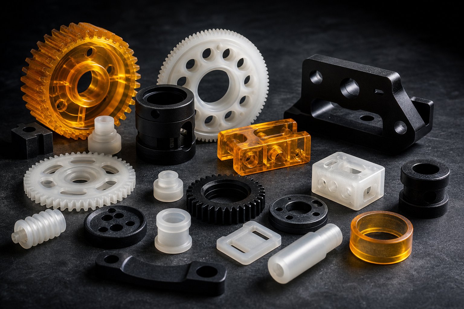
What Engineering Plastics Are and Why They Matter
Imagine you need a part that withstands engine heat, resists aggressive chemicals, and carries a structural load — but metal is too heavy and too expensive for high-volume production. That is exactly where engineering plastics come in. These advanced polymeric materials occupy a critical performance zone between everyday commodity polymers and metals, delivering mechanical strength, thermal endurance, and chemical resistance that general-purpose plastics simply cannot match.
Engineering plastics are a class of high-performance polymeric materials — including polyamides, polycarbonates, acetals, and polyesters — that exhibit continuous use temperatures above 100 °C, tensile strengths typically exceeding 40 MPa, and enhanced dimensional stability, making them suitable for structural and technically demanding applications across automotive, aerospace, medical, and electronics industries.
Defining Engineering Plastics and Their Core Characteristics
What separates an engineering plastic from a commodity one? The answer lies in measurable performance thresholds rather than marketing labels. Commodity polymers like polyethylene (PE), polypropylene (PP), and polystyrene (PS) generally top out at continuous service temperatures of 80-100 °C and tensile strengths in the 20-40 MPa range. Engineering-grade materials push well beyond those limits.
Several core characteristics define this category of engineered materials:
- Continuous use temperature above 100 °C — with high-performance grades capable of exceeding 250 °C.
- Tensile strength typically above 40 MPa — enabling load-bearing and structural roles.
- Enhanced dimensional stability — meaning parts retain their manufactured dimensions under thermal and mechanical stress.
- Superior chemical and abrasion resistance — allowing deployment in harsh operating environments.
At the molecular level, these advantages stem from differences in crystallinity, higher glass transition temperatures, and stronger intermolecular bonding compared to commodity resins. The result is a family of polymers durable enough to replace metal or ceramic parts in automotive, manufacturing, electronic, and transportation applications — often at a fraction of the weight.
Why Engineering Plastics Matter in Modern Manufacturing
Several powerful industry trends are driving demand for these materials. Lightweighting initiatives in automotive and aerospace push designers to swap aluminum, steel, and zinc die-castings for high-strength polymers that can be 40-60% lighter. Miniaturization in electronics demands materials that combine tight dimensional tolerances with electrical insulation and reflow-soldering resistance. And tightening regulatory requirements — from FDA food-contact compliance to UL 94 flammability ratings — mean that only materials with verified, repeatable performance data qualify for critical applications.
The engineering plastics market continues to expand as these converging forces create new use cases across medical devices, industrial automation, electric vehicles, and consumer electronics. Manufacturers who understand what are engineered materials — and more importantly, how to select the right engineering plastic for a specific application — gain a tangible competitive edge in cost, weight, and part longevity.
This article is built around a decision-first framework. Rather than simply listing polymer names and properties, you will find structured comparisons, tiered classifications, a step-by-step material selection process, and practical guidance on processing methods — everything needed to confidently choose, compare, and manufacture with the right material. The journey starts with understanding exactly how these advanced polymers differ from the commodity plastics they are often confused with.
Engineering Plastics vs. Commodity Plastics: What Sets Them Apart
Choosing polypropylene when polyamide is required leads to cracked parts and warranty claims. Choosing polycarbonate when polystyrene would do the job leads to inflated unit costs. The gray zone between these two families of plastic materials is where costly specification errors happen most often — and where a clear, quantitative understanding pays for itself.
Vague statements like "better performance" do not help you make that call. Specific numbers do. So let's draw a hard line between different types of plastic materials and show exactly where commodity polymers reach their ceiling and engineering grade materials take over.
Performance Thresholds That Separate the Two Categories
Commodity plastics — polyethylene (PE), polypropylene (PP), polystyrene (PS), and polyvinyl chloride (PVC) — are the workhorses of packaging, piping, and consumer goods. They account for roughly 80% of all plastic produced globally. They process easily, rarely require drying, and cost between $1.00 and $1.80 per kilogram on current spot markets. The trade-off? Their heat deflection temperatures generally fall between 50 °C and 90 °C, and tensile strengths range from just 10 to 40 MPa.
Engineering plastics — PA66, PC, POM, PBT, and ABS among them — operate above those thresholds. Heat deflection temperatures span 100 °C to 200 °C or higher, while tensile strengths for unfilled grades typically land between 50 and 100 MPa. Glass-reinforced versions push even further; a 30% glass-filled PA66 can exceed 150-180 MPa, entering territory that competes with die-cast metals.
But what drives this performance gap at a molecular level? Three factors stand out:
- Crystallinity and molecular order. Semi-crystalline engineering polymers like PA66 and POM feature highly organized molecular chain structures with strong hydrogen bonding or tight chain packing. This ordered arrangement resists deformation at elevated temperatures far more effectively than the loosely packed amorphous structures common in PS or the relatively simple chain architecture of PE.
- Higher glass transition temperatures. The glass transition temperature (Tg) marks the point where a polymer shifts from rigid to rubbery behavior. Commodity plastics tend to have lower Tg values, which is why a polypropylene container softens noticeably in a hot dishwasher. Polycarbonate, by contrast, has a Tg around 147 °C — keeping it dimensionally stable well above boiling water temperatures.
- Stronger intermolecular forces. Engineering polymers incorporate functional groups — amide linkages in nylon, carbonate groups in PC, ester bonds in PBT — that create stronger intermolecular attractions than the simple hydrocarbon chains found in PE or PP. These forces translate directly into higher tensile strength, better creep resistance, and improved dimensional stability under load.
In practical terms, this molecular difference means a common plastic material like polypropylene will creep and deform under sustained load above 80 °C, while a PA66 part in the same position holds its shape at 120-150 °C. That distinction is not a marginal improvement — it is a categorical difference in what the part can do.
Side-by-Side Comparison of Properties and Cost
The table below puts the two categories head to head across the properties that matter most in material selection. Use it as a first-pass filter when evaluating various plastic materials for a new application.
| Property | PE | PP | PS | PVC | PA66 | PC | POM | PBT |
|---|---|---|---|---|---|---|---|---|
| Category | Commodity | Commodity | Commodity | Commodity | Engineering | Engineering | Engineering | Engineering |
| Continuous Use Temp (°C) | 60-80 | 80-100 | 50-70 | 50-70 | 120-150 | 115-130 | 100-120 | 120-140 |
| Tensile Strength (MPa) | 15-30 | 25-40 | 30-50 | 40-55 | 80-90 | 60-70 | 60-75 | 50-60 |
| Impact Resistance | Good | Moderate | Poor | Moderate | Good | Excellent | Moderate | Moderate |
| Chemical Resistance | Good | Good | Poor | Good | Moderate | Moderate | Good | Good |
| Moisture Absorption | Low | Low | Low | Low | High | Low | Low | Low |
| Relative Cost | $ | $ | $ | $ | $$-$$$ | $$-$$$ | $$ | $$ |
Values represent typical ranges for unfilled grades based on widely established material science principles. Reinforced and filled variants will shift these figures — sometimes dramatically.
A few patterns in this table deserve attention. Notice that PE and PP offer strong chemical resistance at rock-bottom prices — which is precisely why they dominate packaging and piping. Polycarbonate delivers exceptional impact performance but only moderate chemical resistance, a trade-off that catches designers off guard when parts contact solvents or aggressive cleaners. And PA66, for all its mechanical strength, absorbs considerably more moisture than any other material on the list — a characteristic that affects dimensional stability in ways the datasheet alone does not reveal.
When does a commodity plastic actually suffice? Not every application needs engineering grade materials. If your part operates below 80 °C, carries no structural load, faces no chemical exposure beyond water, and has a short service life — think consumer packaging, indoor decorative covers, or disposable housings — a commodity polymer is the right answer. Specifying PA66 or PC for a room-temperature, non-structural bracket is engineering overkill that adds cost without adding value. As one real-world analysis showed, switching from polycarbonate to ABS on an indoor electronics housing that never exceeded 40 °C saved over $400,000 in material costs across a 250,000-unit production run — with zero increase in field failures.
The critical discipline is matching the material to the actual operating environment, not to a worst-case assumption that may never materialize. Cost-per-kilogram is not cost-per-part: an engineering plastic part that consolidates three commodity plastic components into one, or that lasts five times longer in service, can easily be the cheaper solution over its full lifecycle.
These quantitative boundaries provide a starting framework, but within the engineering plastics category itself, performance varies enormously. A standard PA6 and a high-performance PEEK share the "engineering plastic" label while operating in completely different thermal and cost universes — a distinction that demands its own classification system.

A Tiered Classification of Engineering Plastic Families
Lumping PA6 and PEEK into the same bucket because they both qualify as engineering polymers is like grouping a family sedan and a Formula 1 car because they both have engines. The performance gap, the cost gap, and the application logic differ so fundamentally that a single category label obscures more than it reveals. A two-tier framework solves that problem — giving you an immediate mental model for navigating the full landscape of engineered thermoplastics.
Tier 1 — Standard Engineering Plastics
These are the workhorses. Tier 1 materials handle the vast majority of engineering thermoplastic consumption by volume and deliver the best cost-to-performance ratio for structural, mechanical, and electrical applications. Think of them as the default starting point in any material selection exercise:
- Polyamide 6 (PA6) — excellent wear resistance and toughness; widely used in gears, bushings, and structural housings.
- Polyamide 66 (PA66) — higher strength and heat resistance than PA6; the go-to for under-hood automotive components like intake manifolds and radiator end tanks.
- Polycarbonate (PC) — outstanding impact resistance and optical clarity; standard choice for protective enclosures, machine guards, and headlamp lenses.
- Polyoxymethylene (POM/Acetal) — low friction, low moisture absorption, and exceptional dimensional stability; ideal for precision gears, cam followers, and sliding mechanisms.
- Polybutylene Terephthalate (PBT) — strong electrical insulation with low moisture uptake; dominates electrical connector and sensor housing applications.
- Polyethylene Terephthalate (PET) — good chemical resistance and stiffness; commonly used in structural and electrical parts where humidity cycling is a concern.
- ABS — the cost-accessible entry point with good impact resistance and easy processing; suitable for automotive interiors, electronic housings, and prototypes.
For most mechanical and structural applications operating below 150 °C, a Tier 1 material — often with glass-fiber reinforcement — provides everything the application demands. The engineering discipline lies in picking the right one within this tier, not in reflexively jumping to more expensive options.
Tier 2 — High-Performance Engineering Plastics
When Tier 1 materials hit their ceiling — whether that ceiling is thermal, chemical, or regulatory — Tier 2 technical polymers take over. These engineered polymers represent a genuine step-change in capability, with several grades sustaining continuous use above 200 °C and resisting chemicals that would dissolve or degrade standard grades. The trade-off is cost: Tier 2 materials range from roughly four to twenty times the price of their Tier 1 counterparts.
- Polyphenylene Sulfide (PPS) — excellent chemical resistance and dimensional stability; thrives in chemical pump components, automotive under-hood parts, and fluid handling systems where aggressive fluid contact drives the material decision.
- Polyetherimide (PEI/Ultem) — combines high tensile strength (~100-110 MPa) with inherent flame retardancy (UL 94 V-0) and strong electrical insulation; a compelling candidate for aerospace interior components and medical device housings.
- Polyether Ether Ketone (PEEK) — the benchmark for extreme environments, retaining mechanical integrity at continuous temperatures above 250 °C while resisting virtually all industrial solvents and fuels. Medical-grade PEEK is biocompatible and radiolucent, making it the standard where polymer implants are used.
- Polyamide-Imide (PAI) — delivers the highest combination of strength and temperature resistance among injection-moldable engineering polymers, with HDT values exceeding 270 °C. Used for bearing cages, seals, and electrical insulators under extreme mechanical and thermal loads.
- Liquid Crystal Polymers (LCP) — exceptional flow characteristics enable ultra-thin wall molding below 1 mm; the material of choice for miniaturized RF connectors, micro-electronic components, and precision electrical parts requiring reflow soldering resistance.
You will notice a pattern: Tier 2 materials earn their place not through general superiority, but by solving specific problems that Tier 1 grades cannot. PEEK is never the default choice at $50-100+/kg — it earns its specification only when thermal, chemical, or biocompatibility requirements rule out everything else.
Tier 1 vs. Tier 2 at a Glance
The table below distills the essential differences between these two tiers across the three dimensions that matter most during initial material screening.
| Material | Tier | Typical Continuous Use Temp (°C) | Relative Cost | Primary Advantage |
|---|---|---|---|---|
| PA6 | 1 | 80-120 | $-$$ | Wear resistance and toughness at accessible cost |
| PA66 | 1 | 120-150 | $$ | Structural strength with good thermal capability |
| PC | 1 | 115-130 | $$-$$$ | Exceptional impact resistance and transparency |
| POM | 1 | 100-120 | $$ | Dimensional stability and low friction |
| PBT | 1 | 120-140 | $$ | Electrical insulation with low moisture uptake |
| PET | 1 | 100-130 | $$ | Chemical resistance and stiffness |
| ABS | 1 | 80-100 | $ | Cost-effective impact performance and processability |
| PPS | 2 | 200-220 | $$$-$$$$ | Chemical inertness and high-temp dimensional stability |
| PEI (Ultem) | 2 | 170-200 | $$$$ | Flame retardancy with high strength |
| PEEK | 2 | 240-260 | $$$$$ | Ultimate thermal and chemical performance |
| PAI | 2 | 250-270 | $$$$$ | Extreme mechanical strength at extreme temperatures |
| LCP | 2 | 230-240 | $$$-$$$$ | Ultra-thin-wall molding and miniaturization |
Temperature values represent typical ranges for unfilled grades. Glass-fiber and mineral-filled variants can extend thermal ceilings and significantly alter mechanical behavior.
This tiered framework serves as a navigational shortcut. When a design engineer identifies the operating temperature, chemical environment, and budget constraints, the tier assignment immediately narrows the candidate list from a dozen-plus options down to a focused shortlist. The real selection work — comparing specific properties across candidates within a tier — requires the kind of detailed, quantitative data that separates confident material decisions from expensive guesswork.
Key Mechanical and Thermal Properties of Engineering Plastic Materials Compared
Tier assignments tell you where a material sits in the price-performance landscape. But when you are choosing between PA66 and POM for a specific gear assembly, or deciding whether PPS justifies its cost premium over PBT in a connector housing, you need numbers — not categories. This is where most material selection guides fall short. They offer qualitative descriptions ("good heat resistance," "moderate chemical resistance") that sound helpful but leave you guessing when two candidates both earn the same vague label.
The tables and hierarchy below eliminate that guesswork. They consolidate the critical performance dimensions of every major engineering plastic material into a single reference, organized so you can filter candidates by the constraints that matter most in your application.
Comprehensive Material Properties Table
This table covers both standard and special engineering plastics across five selection-critical dimensions. Use it as a side-by-side filter: start with your hardest constraint — usually temperature or chemical environment — and eliminate materials that fall short before evaluating the rest.
| Material | Heat Deflection Temp Range (°C) | Tensile Strength Range (MPa) | Chemical Resistance | Moisture Absorption | Relative Cost |
|---|---|---|---|---|---|
| ABS | 85-105 | 40-55 | Fair | Low | $ |
| PA6 | 65-80 (dry); 160-200 (30% GF) | 70-85 (dry) | Fair | High | $$ |
| PA66 | 75-105 (dry); 240-260 (30% GF) | 80-90 (dry) | Fair | High | $$ |
| PC | 130-140 | 60-70 | Fair | Low | $$-$$$ |
| POM (Acetal) | 105-120 | 60-75 | Good | Low | $$ |
| PBT | 50-65 (unfilled); 200-220 (30% GF) | 50-60 | Good | Low | $$ |
| PET | 70-80 (unfilled); 220-240 (30% GF) | 55-80 | Good | Low | $$ |
| PPO/PPE | 100-150 (blend-dependent) | 55-65 | Good | Low | $$-$$$ |
| PPS | 135 (unfilled); 260+ (40% GF) | 75-90 | Excellent | Low | $$$-$$$$ |
| PEI (Ultem) | 195-210 | 100-115 | Good | Low | $$$$ |
| PEEK | 155-170 (unfilled); 290-320 (30% GF) | 100-115 | Excellent | Low | $$$$$ |
HDT values shown at 1.8 MPa load per ISO 75 methodology. Tensile strength values represent unfilled grades unless noted. Glass-fiber (GF) reinforced variants are included for materials where reinforcement dramatically shifts the HDT, as these filled grades are commonly specified in practice.
A few patterns jump out immediately. Notice how glass-fiber reinforcement transforms the thermal performance of PA66 and PBT — pushing heat deflection temperatures from modest ranges into territory that competes with unfilled high-performance grades at a fraction of the cost. Industry experience confirms that glass-filled PA66 at roughly one-tenth the price of PEEK handles many moderate-temperature structural applications that designers initially assume require premium materials.
You will also spot that moisture absorption cleanly divides the table into two camps. Polyamides (PA6 and PA66) absorb significantly more water than every other engineering thermoplastic listed. This is not a minor footnote — it directly affects dimensional stability, dielectric performance, and mechanical properties in humid environments. Every other material on the list rates low for moisture absorption, which simplifies the selection picture considerably when moisture exposure is a concern.
Chemical resistance tells another useful story. PPS and PEEK stand apart with "Excellent" ratings, handling acids, bases, solvents, and fuels that degrade most Tier 1 materials. PC and ABS, despite their mechanical strengths, rate only "Fair" — a critical detail when parts contact cleaning agents, hydraulic fluids, or industrial solvents.
Reading the Table — Temperature Performance Hierarchy
Temperature is the single most effective first filter in material selection. If your part operates continuously at 180 °C, you have already eliminated eight of the eleven materials above before considering anything else. That one constraint instantly narrows your candidates from an overwhelming list to a focused shortlist of two or three.
Here is how the major types of hard plastic stack up by continuous use temperature band:
- Up to 80-100 °C: ABS — adequate for indoor electronics enclosures and non-structural housings where thermal loads stay modest.
- Up to 120 °C: PA6, PBT, PET — suitable for moderately warm environments like underbody automotive components, electrical connectors, and appliance internals.
- Up to 150 °C: PA66, PC, POM, PPO/PPE — the sweet spot for under-hood automotive parts, industrial power tool housings, and mechanical components subject to friction-generated heat.
- Up to 200 °C: PPS, PEI — required where sustained high heat combines with chemical exposure or flammability mandates, such as chemical processing equipment, aerospace interior panels, and sterilizable medical devices.
- 250 °C and above: PEEK, PAI, LCP — reserved for the most extreme thermal environments including jet engine components, downhole oil-and-gas tools, and high-temperature semiconductor handling equipment.
Imagine you are specifying a housing for an industrial motor controller. Ambient temperature inside the enclosure peaks at 130 °C during sustained operation. That single data point eliminates ABS, PA6, PBT, and PET from consideration. Your practical candidates are PA66, PC, POM, or PPO — and from there, secondary factors like chemical exposure, impact requirements, and cost narrow the field to one or two finalists.
One important caveat before you commit to this hierarchy as a rigid rule: fiber reinforcement and mineral fillers can meaningfully shift these temperature ceilings. A 30% glass-filled PBT, for instance, can achieve heat deflection temperatures above 200 °C — a range that unfilled PBT cannot approach. Similarly, carbon-fiber-reinforced PEEK pushes usable temperatures beyond 300 °C in structural applications. These filled and reinforced variants effectively expand the selection space, sometimes allowing a lower-tier base resin to meet requirements that would otherwise demand a jump to an expensive Tier 2 material.
That interaction between base resin properties and reinforcement additives is precisely what makes the next stage of material selection — understanding how fillers, fibers, and modifiers reshape performance — so critical to getting the specification right without overspending.
Industry Applications Mapped to Specific Engineering Plastics
Knowing that PA66 handles 150 °C and POM offers low friction is useful in a datasheet review — but it does not tell you which material belongs inside a radiator end tank versus a conveyor slide plate. Real-world material selection happens at the intersection of polymer properties and application-specific demands: temperature profiles, chemical exposures, regulatory requirements, and mechanical load patterns that vary dramatically from one industry to the next.
This section bridges that gap. Instead of generic "automotive" or "medical" labels, you will find specific engineered plastic products mapped to the exact use cases where they deliver proven performance — along with the compliance considerations that often override pure engineering logic.
Automotive and Aerospace Applications
Few industries push engineering plastic products harder than automotive and aerospace. Parts face sustained heat, vibration, chemical splash, and relentless cost pressure — all simultaneously. Here is how the major materials map to specific roles:
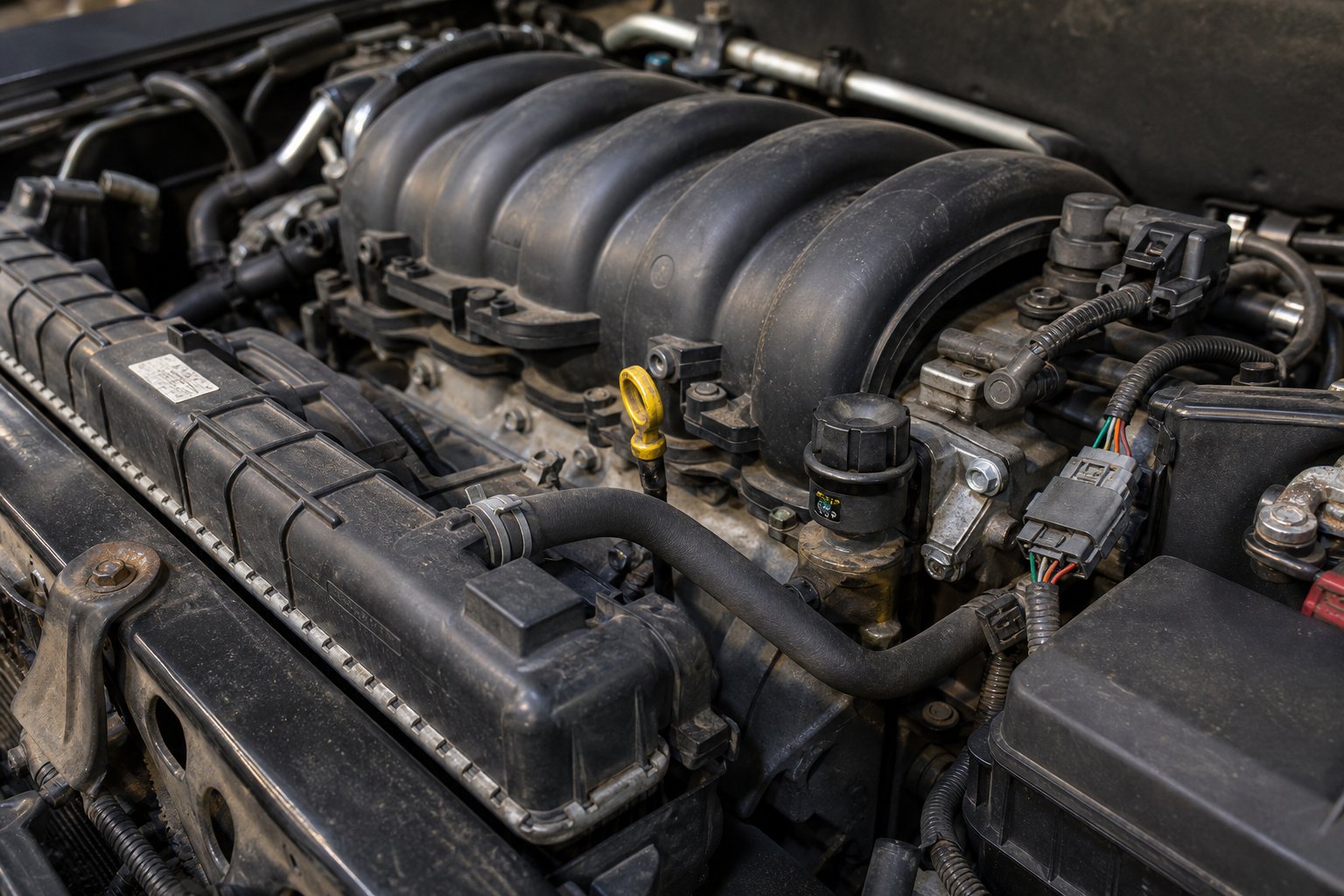
- PA66 — under-hood workhorses like intake manifolds, radiator end tanks, engine covers, and structural brackets. Glass-filled grades (typically 30% GF) dominate here, delivering tensile strengths of 150-180 MPa with heat deflection temperatures above 200 °C.
- POM — fuel system components, gear mechanisms, window regulator assemblies, and any application where low friction and tight dimensional tolerances matter more than raw strength.
- PBT — electrical connectors, sensor housings, and relay bodies where low moisture absorption ensures consistent geometry through humidity and temperature cycling.
- PC — headlamp lenses, panoramic sunroof panels, and instrument cluster covers that require optical clarity combined with impact resistance.
- PEEK — aerospace bearing cages, bushings, seal rings, and structural fasteners in jet engines and flight control systems where continuous temperatures exceed 200 °C and chemical inertness is non-negotiable.
The metal-to-plastic conversion trend is a major driver behind this material mapping. Replacing aluminum, steel, brass, or zinc die-castings with engineered plastic alternatives often cuts component weight by 40-60% — a figure validated in production case studies where glass-filled PA66 brackets replaced CNC-machined aluminum equivalents with a 35% mass reduction. Beyond weight savings, these conversions eliminate corrosion entirely, remove secondary operations like anodizing or plating, and enable design consolidation. Imagine a single injection-molded housing that integrates mounting bosses, snap fits, wire routing channels, and structural ribs — replacing an assembly of three stamped metal parts plus hardware. That is not just lightweighting; it is a fundamental redesign of how engineered plastic systems deliver function.
Medical, Electronics, and Industrial Applications
Outside the automotive world, engineered plastic components serve equally demanding — and often more tightly regulated — roles.
Medical devices require materials that withstand repeated sterilization cycles without degrading. PEI (Ultem) and PEEK are the standard choices for sterilizable surgical instrument handles, reusable trays, and orthopedic implant components. PC finds its place in device housings and diagnostic equipment enclosures where impact resistance and transparency support both durability and visual inspection needs. Medical-grade PEEK, specifically, is biocompatible and radiolucent — meaning it does not interfere with X-ray or MRI imaging — making it the polymer standard for implant applications.
Electronics demand a different set of priorities: miniaturization, electrical insulation, and compatibility with surface-mount technology (SMT) soldering processes. PBT and LCP dominate miniaturized connector bodies and precision switch housings. LCP's exceptional flow characteristics enable wall thicknesses below 1 mm, which is critical as electronic assemblies shrink. PPS earns its specification in SMT-compatible components because it resists reflow soldering temperatures (typically 260 °C peak) without warping or outgassing — a requirement that eliminates most Tier 1 materials from consideration.
Industrial applications lean toward wear resistance and chemical durability. POM serves as the default material for conveyor chain links, guide rails, and slide plates where low friction keeps systems running without lubrication. PA — particularly glass-filled grades — handles wear pads, rollers, cable guide wheels, and structural brackets in material handling equipment. PPS steps in for chemical pump components, valve bodies, and fluid handling manifolds exposed to aggressive solvents or hot cleaning solutions.
Regulatory and Compliance Considerations
Here is a reality that often surprises first-time specifiers: the best-performing engineered plastic in the world is useless if it lacks the right certification for your application. Regulatory compliance frequently eliminates candidates before mechanical or thermal properties even enter the discussion. And compliance is grade-specific, not polymer-family-wide — a commercial-grade PEEK and a medical-grade PEEK carry entirely different documentation packages, testing histories, and price points.
The key certifications and standards you will encounter include:
- UL 94 Flammability Ratings — V-0 (self-extinguishing within 10 seconds, no flaming drips) is required for most electrical enclosures and connector bodies. Flame-retardant grades of PBT, PA66, PPS, and PC are commonly available in V-0 configurations. V-1 and V-2 allow progressively more dripping. HB (horizontal burn) is the baseline rating — insufficient for most regulated electrical applications.
- FDA 21 CFR Food Contact Compliance — mandatory for any component contacting food or beverages during processing, packaging, or dispensing. Compliant grades exist for PEEK, select POM and PA formulations, PEI, and high-purity PPS. Compliance documentation comes at the specific material grade level through the resin supplier.
- ISO 10993 Biocompatibility — required for medical devices based on contact type and duration. Testing under ISO 10993 includes cytotoxicity, sensitization, and depending on implant duration, systemic toxicity and hemocompatibility. PEEK and PEI are the most commonly certified engineering polymers for extended body-contact and implant applications.
- RoHS and REACH Compliance — essential for electronics and automotive components destined for EU markets. Materials must be verified free from restricted substances including lead, cadmium, mercury, and certain halogenated flame retardants. Certification documentation is provided at the material grade level by the supplier.
- Automotive OEM Material Approval — goes beyond generic standards. Validated grades undergo 1,000+ hour heat aging, vibration endurance, moisture cycling, and chemical resistance testing against fuels and lubricants before earning a position on OEM-specific approved material lists.
Missing any of these certifications at the specification stage creates delays, redesigns, and requalification costs that dwarf any material price difference. The smartest approach? Confirm regulatory requirements at Step 1 of your selection process — before investing time evaluating mechanical and thermal properties of candidates that may not qualify.
With application requirements and compliance constraints clearly mapped, the next challenge shifts from what material to use to how to choose it systematically — a decision process that benefits enormously from a structured, step-by-step framework rather than intuition alone.
How to Choose the Right Engineering Plastic
You have the property data. You know which tier each material falls into. You understand the regulatory landscape. Yet faced with a real part specification — say, a pump housing exposed to hot glycol at 110 °C under cyclic loading — many engineers still default to gut instinct or past habit. That approach works until it doesn't, and when it fails, the cost shows up as cracked parts, swollen bearings, or a six-month requalification cycle.
A structured decision framework eliminates that guesswork. The process below walks through six filters in priority order, progressively narrowing the field from dozens of engineered polymer compounds down to a shortlist of one or two viable candidates.
A Step-by-Step Material Selection Framework
Each step eliminates materials that cannot meet a specific requirement. Work through them sequentially — the order matters because the first filters remove the most candidates with the least effort.
- Define the continuous operating temperature. This is the single most powerful filter. A 160 °C requirement instantly eliminates ABS, PA6, POM, PBT, and PC from consideration, leaving only PA66 (borderline), PPS, PEI, and PEEK. Do not confuse peak exposure with continuous service — a brief thermal spike to 150 °C is very different from sustained operation at that temperature for thousands of hours.
- Identify the chemical exposure environment. Map every fluid, gas, and cleaning agent the part will contact. Fuels, hydraulic fluids, solvents, and acidic condensates each attack different polymers. PPS and PEEK handle aggressive chemical environments; PC cracks in contact with certain solvents; PA degrades in strong acids. A single incompatible chemical can eliminate an otherwise perfect candidate.
- Determine the mechanical load type. Static loads, dynamic/cyclic loading, sudden impact, and sustained creep stress each favor different engineered polymer formulations. Glass-filled PA66 excels under static structural loads. POM handles repetitive sliding and wear. PC absorbs sudden impacts. PEEK resists long-term creep at elevated temperatures. Matching load type to material behavior prevents the slow-motion failures that short-term tensile tests cannot predict.
- Check regulatory requirements. Confirm FDA, UL 94, RoHS/REACH, ISO 10993, or OEM-specific mandates before investing time in detailed property comparisons. A material that lacks the required certification is not a viable candidate — regardless of how well its mechanical properties fit.
- Evaluate moisture exposure. This step is critical for polyamides. If the part operates in humid or wet conditions and dimensional stability is important, PA6 and PA66 require careful evaluation. PA66 absorbs 1.0-2.5% moisture, causing measurable swelling that can push precision features out of tolerance. POM, PBT, PPS, and PEEK all absorb far less moisture and maintain tighter dimensional consistency in variable-humidity environments.
- Assess cost constraints and production volume. Material cost per kilogram is not part cost. A $6/kg resin injection-molded at high volume produces dramatically different economics than the same resin CNC-machined in batches of fifty. Factor in tooling amortization, scrap rates, secondary operations, and expected service life. A more expensive material that lasts five times longer or consolidates multiple cheaper components into one often delivers the lowest total cost of ownership.
By the time you reach Step 6, you will typically have two or three candidates remaining. At that point, prototype testing under realistic service conditions — not just datasheet comparison — makes the final call.
Reinforced and Filled Variants — Expanding the Selection Space
Here is where the decision gets interesting. The six-step framework above evaluates base resins, but in practice, many applications specify filled or reinforced grades that substantially alter the performance envelope. Think of performance modifiers for engineering plastics — glass fibers, carbon fibers, mineral fillers — as a way to stretch a Tier 1 material into territory that would otherwise require a jump to a more expensive Tier 2 resin.
Glass-fiber-filled (GF) nylon is the most widely used engineered composite in structural applications. Adding 30% glass fiber to PA66 roughly doubles tensile strength and can push heat deflection temperature above 240 °C — competitive with unfilled PPS at roughly one-tenth the material cost. Carbon-fiber-reinforced PEEK pushes stiffness toward aluminum territory while reducing thermal expansion to near-metallic levels. Mineral-filled PBT improves dimensional stability and reduces warpage in thin-wall electrical connectors.
But these gains are not free. Reinforcement fibers reduce impact resistance, make the material more brittle, and significantly increase abrasiveness during processing — accelerating wear on molds, screws, and barrels.
The table below illustrates how 30% glass-fiber reinforcement shifts the key properties of three commonly specified base resins:
| Material | Tensile Strength (MPa) | Heat Deflection Temp (°C, 1.8 MPa) | Impact Resistance |
|---|---|---|---|
| PA66 (unfilled) | 80-90 | 75-105 | Good |
| PA66 + 30% GF | 170-190 | 240-260 | Moderate (reduced) |
| PBT (unfilled) | 50-60 | 50-65 | Moderate |
| PBT + 30% GF | 120-140 | 200-220 | Low-Moderate (reduced) |
| PEEK (unfilled) | 100-115 | 155-170 | Good |
| PEEK + 30% GF | 155-165 | 290-320 | Moderate (reduced) |
Values represent typical ranges from established material science data. Comparative testing of reinforced PA66 shows that glass fiber roughly doubles tensile strength while reducing elongation at break from ~60% to ~3%, confirming the stiffness-for-ductility trade-off inherent in all fiber-reinforced grades.
The takeaway? Specialist engineering plastics are not always necessary. A glass-filled Tier 1 resin can deliver thermal and mechanical performance that overlaps with unfilled Tier 2 materials — at a dramatically lower price point. The selection framework's job is to identify when that overlap exists and when genuine high-performance base resins are the only viable path.
Cost-vs-Performance Decision Logic
Every material specification is ultimately a cost decision. The question is never "what is the best material?" — it is "what is the least expensive material that meets every functional requirement with an acceptable safety margin?" Here is a practical tiered logic for making that call:
- Commodity plastics suffice when the part is non-structural, operates below 80 °C, faces no chemical exposure, and has a short or disposable service life. Indoor decorative covers, packaging inserts, and cable management clips fall into this zone. Specifying an engineering grade here wastes money.
- Standard (Tier 1) engineering plastics are justified when the part carries moderate mechanical loads, operates between 100 and 150 °C, requires dimensional stability, or must meet UL 94 or FDA requirements. This tier — PA66, PC, POM, PBT — covers the majority of structural, mechanical, and electrical applications in automotive, industrial, and consumer electronics. Glass-filled variants extend the envelope further, making Tier 1 the sweet spot for cost-to-performance optimization.
- High-performance (Tier 2) plastics are necessary when continuous temperatures exceed 150 °C, the chemical environment degrades Tier 1 options, biocompatibility or aerospace-grade certifications are mandated, or long-term creep resistance at elevated temperatures is non-negotiable. These are materials of last resort in a cost sense — you specify PPS, PEI, or PEEK because nothing cheaper survives the service environment, not because they offer a comfortable safety margin over a less expensive alternative.
The costliest material selection error is not choosing the wrong plastic — it is choosing an unnecessarily expensive one. A PA66 with 30% glass fill at $5-8/kg solves the same problem as unfilled PEEK at $50-100/kg in more applications than most engineers expect.
Selecting the right engineered composite or base resin is only half the equation. The material's promised properties only materialize if the processing method — injection molding, extrusion, machining, or additive manufacturing — is properly matched to the polymer's unique thermal, rheological, and mechanical demands. A mismatched process does not just reduce quality; it can degrade the material itself before the part ever reaches service.
Processing Methods and Manufacturing Considerations for Engineering Plastic Manufacturing
A perfectly selected resin becomes a perfectly ruined part if the manufacturing process cannot handle its demands. Polycarbonate that yellows during extrusion, nylon connectors that crumble from hydrolysis in the barrel, glass-filled PBT that chews through a screw in weeks — these failures have nothing to do with the material choice and everything to do with how the material was processed. Plastics engineering at this level requires matching every polymer to a manufacturing method that respects its unique thermal window, moisture sensitivity, and rheological behavior.
This is the gap most material guides ignore entirely. They stop at "what to use" and never address "how to make it." The reality of engineering plastic manufacturing is that each polymer brings processing constraints that commodity resins simply do not.
Processing Compatibility by Manufacturing Method
Not every polymer works with every process. Some materials extrude beautifully but machine poorly. Others injection-mold with precision but cannot be 3D printed. The table below maps each major material to its viable processing methods and flags the special requirements that trip up manufacturers transitioning from commodity work.
| Material | Injection Molding | Extrusion | CNC Machining | 3D Printing (FDM/SLS) | Key Processing Notes |
|---|---|---|---|---|---|
| ABS | Excellent | Excellent | Good | Excellent (FDM) | Dry to <0.08%; melt temp 220-260 °C; most forgiving of the group |
| PA6 | Excellent | Good | Good | Good (SLS/FDM) | Mandatory pre-drying to <0.2%; melt temp 230-260 °C; mold temp 60-90 °C; hygroscopic — reabsorbs moisture rapidly after drying |
| PA66 | Excellent | Good | Good | Limited | Mandatory pre-drying to <0.2%; melt temp 260-290 °C; mold temp 70-100 °C; narrow window between melting and degradation |
| PC | Excellent | Good | Excellent | Good (FDM) | Mandatory pre-drying to <0.02%; melt temp 280-310 °C; mold temp 80-120 °C; very sensitive to moisture — hydrolysis degrades molecular weight invisibly |
| POM | Excellent | Good | Excellent | Limited | Melt temp 190-210 °C; mold temp 60-100 °C; annealing recommended for dimensionally critical parts; formaldehyde off-gassing requires ventilation |
| PBT | Excellent | Good | Good | Limited | Pre-drying recommended to <0.04%; melt temp 230-260 °C; fast crystallization — short cycle times; sensitive to hydrolysis during processing |
| PET | Good | Excellent | Fair | Limited | Mandatory pre-drying to <0.005%; melt temp 260-280 °C; extremely moisture-sensitive during processing; vented extruder recommended |
| PPS | Good | Fair | Good | SLS available | Melt temp 290-320 °C; high mold temp 130-150 °C; minimal moisture absorption; corrosive off-gassing — requires corrosion-resistant tooling |
| PEI (Ultem) | Good | Fair | Excellent | Good (FDM/SLS) | Pre-drying to <0.02%; melt temp 340-400 °C; high mold temp 140-175 °C; requires high-capacity heating equipment |
| PEEK | Fair | Fair | Excellent | Good (FDM/SLS) | Pre-drying to <0.02%; melt temp 370-400 °C; mold temp 160-200 °C; annealing critical for crystallinity and dimensional stability; requires specialized high-temp tooling |
Melt temperature ranges represent general processing guidelines from established plastics engineering principles. Specific grades and filled variants may require adjustments — always confirm with the resin supplier's datasheet.
A few patterns deserve attention. Notice how mandatory pre-drying appears for nearly every material except POM and PPS. Hygroscopic resins like PA and PC are not simply "better when dried" — they undergo hydrolysis at melt temperature, breaking polymer chains and permanently reducing mechanical strength. The damage is chemical, irreversible, and often invisible in the finished part. This is why production of engineering polymers demands dehumidified drying systems — not just hot-air hoppers — with strict moisture verification before processing begins.
Also notice how CNC machining from engineering plastic sheet or rod stock rates "Good" to "Excellent" across most materials. Machining from extruded stock shapes — sheets, rods, tubes, and plates — is the default path for prototypes, low-volume production, and applications where mold tooling cannot be justified. POM and PEEK machine particularly well, producing tight tolerances and excellent surface finishes. PEI, despite its high processing temperatures in melt form, is also an outstanding machining candidate. For production runs where engineering plastic sheet stock serves as the starting point, the quality of that extruded stock directly depends on how well the extrusion process itself was controlled — a point that leads directly into the next critical topic.
Extrusion Considerations for Engineering Plastics
Extrusion is how those stock shapes — rods, tubes, profiles, and sheets — get produced in the first place. It is also the process where the gap between commodity and engineering polymers creates the most manufacturing problems, because extrusion demands sustained thermal stability, consistent melt homogeneity, and steady output pressure over hours or days of continuous operation.
Here is what changes when you move from extruding polyethylene to extruding PA66 or PC:
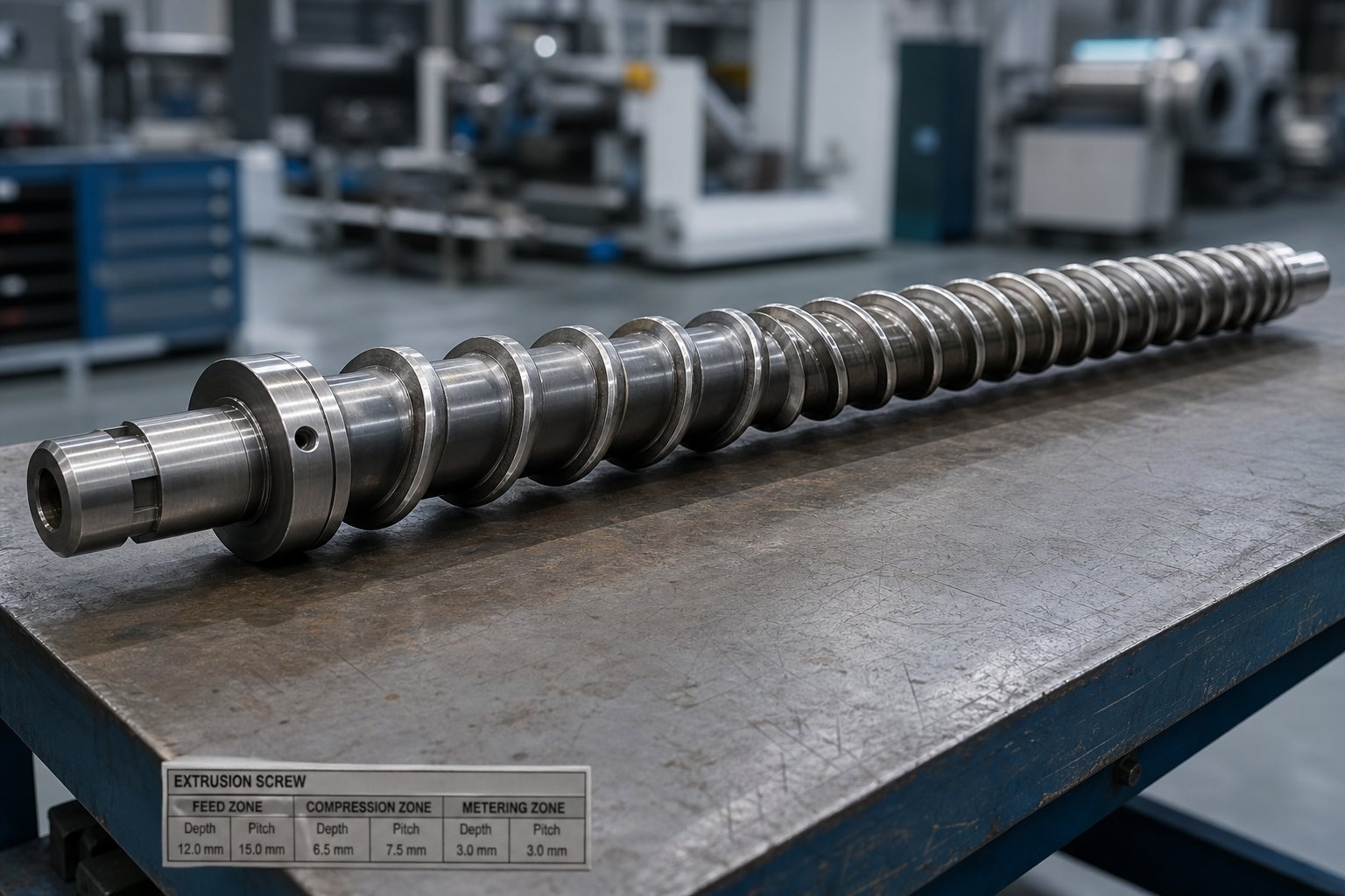
- Screw design must match the polymer's melt behavior. Engineering resins process at higher temperatures with narrower windows between complete melting and thermal degradation. A compression ratio optimized for commodity polymers — typically 3.5:1 to 4:1 — often generates excessive shear heat when applied to higher-viscosity engineering grades. The result is barrel temperature overrides, discoloration, and degraded output. Engineering polymers typically require moderate compression ratios carefully matched to their specific melt rheology.
- L/D ratios need to be longer. Engineering resins' high melt temperatures and the frequent need for vented screw designs push optimal L/D ratios toward 28:1 to 32:1 — significantly longer than the 24:1 typical for commodity polyolefin extrusion. Shorter screws copied from a commodity line leave insufficient residence time for complete melting and no room for a vent zone to remove residual moisture.
- Thermal management is less forgiving. Where PE and PP tolerate broad temperature profiles, polycarbonate and nylon sit on a knife's edge. PC processes at 280-310 °C with a narrow margin before yellowing and degradation set in. Barrel zone temperatures must be precisely controlled, and the screw's shear contribution to melt temperature — which is geometry-dependent — must be accounted for in the thermal design.
Glass-filled and mineral-filled compounds add another layer of complexity. High-performance engineering plastic granules containing 30-40% glass fiber are among the most abrasive materials a screw and barrel will ever encounter. The fillers do not melt — they remain as hard, rigid particles grinding against metal surfaces throughout the entire barrel length. As industry research on thermoplastic composite extrusion confirms, glass-fiber and mica fillers cause aggressive abrasive wear in the feed section and transition zone, where unmelted pellets with filler particles concentrated near their surfaces scrape directly against unprotected screw root metal. A standard nitrided screw processing glass-filled nylon wears out far faster than its expected service life would suggest on unfilled resin.
Beyond wear, filled compounds also alter the screw's volumetric compression behavior. Because fillers increase the resin's specific gravity without contributing meltable volume — a 40% talc-filled polypropylene is 35% denser than the neat resin, yet 40% of its volume is non-compressible filler — a screw designed for unfilled material generates excessive pressure differentials in the transition zone when processing filled grades. The symptoms are predictable: temperature overrides in middle barrel zones, inconsistent output, and accelerated wear patterns concentrated on the push side of the flight.
Why does this matter so much? Because a generic screw geometry designed for commodity polymers often produces three simultaneous problems when used with engineering resins: poor melt homogeneity from inadequate mixing, thermal degradation from mismatched compression, and premature equipment failure from abrasive wear. Each problem feeds the others — uneven melting raises local shear, higher shear accelerates wear, and worn flights reduce pumping consistency.
The solution is application-specific screw engineering — matching geometry, compression ratio, flight depth, mixing sections, and metallurgy to the actual polymer being processed. For manufacturers who need tailored screw geometry, optimized compression ratios, and wear-resistant material selection specifically engineered for demanding polymers and filled compounds, NANHAIYA offers a custom screw design service that addresses exactly these plastic engineering challenges. Rather than forcing a universal screw geometry onto materials that punish generic specifications, custom-designed screws match the specific melt behavior, filler content, and output requirements of each application — reducing barrel overrides, extending service life, and delivering the consistent melt quality that engineering resins demand.
Getting the processing equipment right is essential — but even a perfectly configured manufacturing line cannot compensate for material selection errors. And the most common selection mistakes are not the obvious ones; they are subtle misunderstandings about how these polymers actually behave outside the controlled conditions of a datasheet test.
Common Selection Mistakes and Material Failure Modes in Technical Plastics
A cracked polycarbonate housing. A nylon gear that swells out of tolerance three months after installation. A PET connector that crumbles during reflow soldering. These failures rarely stem from choosing the wrong polymer family — they stem from misunderstanding how the right polymer behaves under real-world conditions that datasheets only partially represent. The gap between laboratory test values and field performance is where the most expensive engineering mistakes hide.
Every experienced plastic engineer has a story about a part that passed every prototype test, then failed in service. The root cause almost always traces back to one of a handful of predictable — and preventable — selection pitfalls.
Common Material Selection Mistakes
These are not obscure edge cases. They are the pitfalls that account for the majority of field failures in technical plastics applications, and each one reflects a gap between how materials are tested and how they actually perform:
- Selecting PA (nylon) for dimensionally critical parts without accounting for moisture absorption. PA6 can absorb up to 9.5% moisture by weight at saturation, and even at a standard 50% relative humidity, it reaches 2.5-3.0% equilibrium moisture content. That moisture causes linear expansion of approximately 0.15-0.20% per 1% absorbed in the flow direction — and up to 0.40-0.50% in the transverse direction. For a 200 mm part, that translates to measurable, functional dimensional change that can push press-fit joints, snap features, and bearing bores out of tolerance.
- Specifying materials based on dry-as-molded datasheet values. Nylon datasheets report tensile strength of 80-90 MPa. That number is accurate — for a specimen tested within hours of molding, at less than 0.2% moisture content. At 50% relative humidity equilibrium, tensile strength drops roughly 28%, and flexural modulus falls by approximately 40%. Designing to dry-as-molded values builds in a safety margin that does not actually exist in service.
- Ignoring notch sensitivity in PC and POM. Polycarbonate delivers exceptional impact resistance on smooth specimens, but sharp internal corners, gate vestiges, or machining marks act as stress concentrators that dramatically reduce impact performance. POM behaves similarly — its otherwise good toughness plummets when parts feature tight radii or weld lines under load. Generous fillet radii and gate placement away from high-stress zones are not optional refinements; they are structural necessities.
- Overlooking creep behavior under sustained loads. Short-term tensile test data tells you how a material performs under a load applied for seconds. Many structural applications — clips, springs, press-fit housings — apply load for years. Creep rupture occurs under constant load over time, and polymers that look strong in a tensile test can deform progressively and fail under sustained stress that is well below their rated tensile strength. Isochronous stress-strain curves, not short-term tensile values, are the correct design data for sustained-load applications.
- Failing to account for UV degradation in outdoor applications. PA and ABS are particularly vulnerable. Without UV stabilizers, nylon exposed to direct sunlight loses surface integrity within months — chalking, cracking, and losing tensile strength progressively. ABS yellows and embrittles. Specifying outdoor-use parts without confirming UV-stabilized or carbon-black-filled grades is a predictable path to warranty claims.
Notice a pattern? Every one of these mistakes involves a gap between controlled test conditions and actual service environments. The datasheet is not wrong — it simply describes one narrow set of conditions that may bear little resemblance to where the part actually lives.
Degradation Mechanisms and How to Prevent Them
Beyond selection pitfalls, engineering polymers face specific degradation mechanisms that destroy performance even when the initial material choice was correct. Understanding these mechanisms — and their prevention — is as important as choosing the right resin in the first place.
- Hydrolysis in PET and PBT. These polyester-based polymers undergo chemical chain scission when exposed to moisture at processing temperatures. The damage happens inside the barrel, before the part is even formed. A PET resin processed at 0.02% moisture content performs as expected; the same resin processed at 0.05% suffers irreversible molecular weight loss, producing brittle parts with dramatically reduced impact strength. Prevention: dehumidifying drying to below 0.005% moisture content immediately before processing, with sealed feed systems to prevent reabsorption.
- Thermal degradation from exceeding processing windows. Engineering with polymers that have narrow processing windows — PC, PA66, PEEK — demands precise temperature control. PC yellows and loses impact strength when barrel temperatures exceed 310 °C or when residence time is too long. PA66 sits just 15-20 °C between complete melting and the onset of oxidative degradation. Prevention: verify actual melt temperature with a probe (not barrel setpoints alone), minimize residence time, and purge thoroughly during shutdowns.
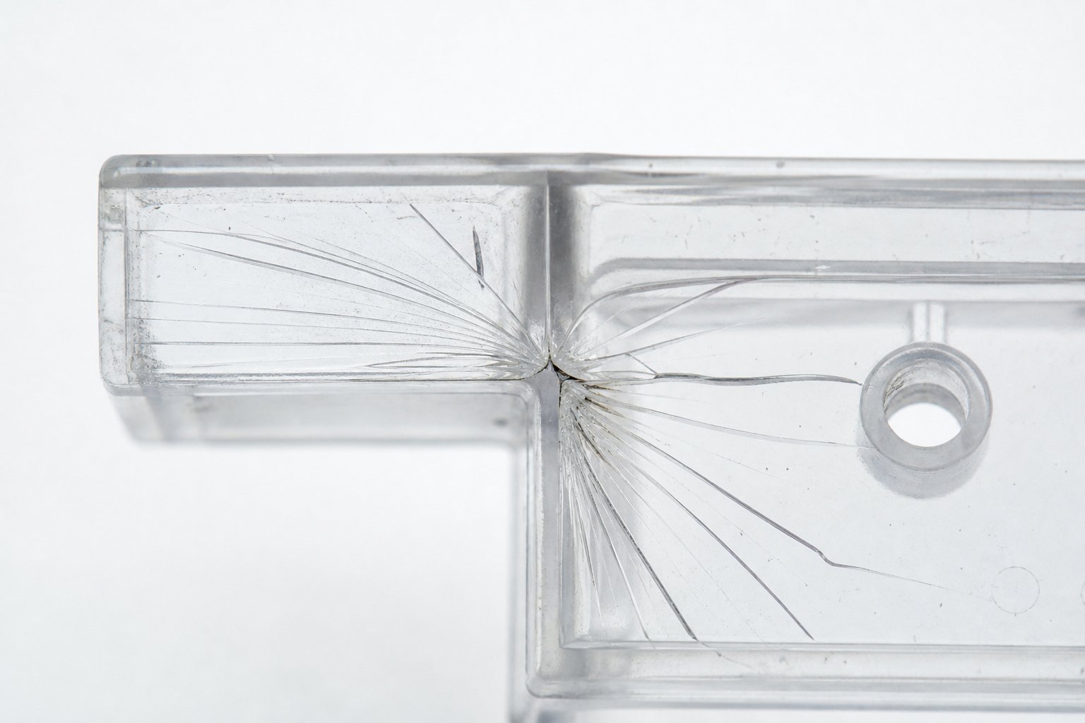
- Environmental stress cracking (ESC) in polycarbonate. PC is famously tough — until it contacts certain chemicals under stress. Common culprits include isopropanol, acetone, toluene, and even some commercial cleaning agents. The mechanism is insidious: chemicals weaken the polymer structure while stress is applied, leading to crack formation at stress levels far below the material's rated strength. Parts can appear perfect for months, then crack suddenly when a maintenance technician wipes them down with the wrong cleaner. Prevention: verify chemical compatibility for every substance the part will contact — including cleaning agents — and specify stress-crack-resistant PC grades or alternative materials (PBT, PPS) for chemically exposed applications.
- Creep deformation under sustained load at elevated temperatures. All thermoplastics creep. The question is how much and how fast. A PA66 bracket supporting a 5 kg static load at room temperature may hold indefinitely. The same bracket at 100 °C under the same load creeps progressively, sagging over weeks or months until it fails or pushes mating components out of alignment. Prevention: design to creep data (isochronous stress-strain curves) rather than short-term strength values, apply appropriate safety factors, and consider glass-fiber reinforcement to reduce creep rates dramatically.
The common thread across all four mechanisms? They are invisible during initial testing. A part that passes quality inspection on day one can fail catastrophically in month six because degradation is progressive and often undetectable without destructive testing. Engineering with polymers at a professional level means designing against the failure mode, not just to the performance target.
Moisture Conditioning — The Nylon Challenge
Polyamide hygroscopicity deserves its own discussion because no other engineering thermoplastic behavior causes as much confusion — or as many field failures — as moisture absorption in nylon. If you specify PA6 or PA66 for any application where dimensions, stiffness, or strength matter, this section determines whether your parts succeed or fail.
Datasheet values for nylons represent dry-as-molded conditions — typically below 0.2% moisture content. In real-world service, nylon parts equilibrate to their environment and can absorb 2-3% moisture at 50% relative humidity, fundamentally altering mechanical properties, dimensional stability, and wear behavior compared to published specifications.
Here is what that moisture actually does. Water molecules penetrate the amorphous regions of the polymer and act as a plasticizer, forcing crystalline structures apart. The result is a softer, tougher, but weaker and less stiff material. At 50% relative humidity equilibrium, tensile modulus drops approximately 35%, flexural modulus drops roughly 40%, and elongation at break can increase by 250% or more. Impact resistance, interestingly, improves — Izod impact values can double from dry-as-molded to conditioned state. The material becomes more forgiving of sudden loads while losing its ability to maintain shape under sustained ones.
Dimensionally, the swelling is anisotropic — meaning it is greater perpendicular to the mold flow direction than parallel to it. At room temperature and 50% relative humidity, equilibrium moisture content for nylon tends to remain around 2%, which corresponds to a size increase of roughly 0.5-0.6%. That might sound small, but on a 150 mm precision housing with tight bearing tolerances, 0.6% growth represents nearly a full millimeter — enough to jam a sliding mechanism or loosen an interference fit.
How should you design around this? Three practical strategies:
- Design to conditioned-state properties, not dry-as-molded values. If your part will spend its service life in ambient conditions, the conditioned data represents reality. Use dry-as-molded data only for parts that operate in sealed, desiccated environments.
- Consider alternative materials for dimensionally critical applications. POM absorbs roughly 0.2% moisture under the same conditions that cause PA6 to absorb 2.5-3.0%. PBT and PET offer similar dimensional stability advantages. If a tight-tolerance part cannot accommodate nylon's swelling, switching to acetal or polyester is often smarter than fighting physics with tighter initial tolerances.
- Specify conditioning requirements for assembly-critical parts. If a nylon part must be at a specific moisture content for assembly — to hit a target dimension for a press-fit or snap-fit feature — define the conditioning protocol: temperature, humidity, duration, and acceptable moisture range. Leaving conditioning to chance invites part-to-part variation that no amount of mold precision can overcome.
One final detail that catches manufacturers off guard: once dried for processing, nylon reabsorbs moisture at approximately 0.1% per hour at 23 °C and 50% relative humidity. That means dried material left in an open hopper for four hours has already reabsorbed enough moisture to risk hydrolysis during processing. Sealed feed systems and strict time limits between drying and molding are not best practices — they are mandatory for consistent part quality.
Understanding these failure modes and selection pitfalls transforms material selection from a datasheet exercise into a true engineering discipline. The question that remains is how to synthesize all of this knowledge — properties, applications, processing constraints, and failure prevention — into a coherent strategy that carries through from specification to finished part.
Turning Material Selection into Manufacturing Success
Selecting a polymer from a datasheet is one decision. Turning that polymer into a part that performs reliably for years in the field is an entirely different challenge — and the distance between those two milestones is where costly failures concentrate. Every chapter of this guide has reinforced a single truth: engineered plastics only deliver their promised performance when material knowledge, application awareness, and processing execution work together as a system, not as isolated steps.
Key Takeaways for Selecting and Processing Engineering Plastics
If you take nothing else from this guide, anchor your next material decision on these three principles:
Start with the operating environment — temperature, chemical exposure, moisture, UV, and regulatory mandates — rather than defaulting to a familiar material. Design to real-world conditioned properties, not dry-as-molded datasheet values. And match your processing equipment and parameters to your chosen material, because generic screw geometries and loose thermal controls destroy performance before a part ever reaches service.
The tiered classification introduced earlier gives you a fast mental framework for every new project. Tier 1 materials — PA66, PC, POM, PBT, and ABS — handle the vast majority of structural and electrical applications below 150 degrees C at the best cost-to-performance ratio. Glass-fiber reinforcement stretches their envelope even further, often overlapping with the thermal and mechanical territory of unfilled Tier 2 resins. Only when continuous temperatures exceed 150 degrees C, aggressive chemicals rule out standard grades, or biocompatibility and aerospace-grade certifications are mandated does the jump to Tier 2 materials — PPS, PEI, PEEK, PAI, LCP — become justified.
That logic keeps you from two equally expensive errors: under-specifying a material that fails in the field, and over-specifying one that inflates unit costs without adding functional value. Both mistakes trace back to the same root cause — skipping a disciplined, step-by-step evaluation in favor of intuition or habit.
The six-step selection framework (temperature, chemical environment, load type, regulatory requirements, moisture exposure, cost) works because it eliminates candidates systematically. By the time you reach the final step, your shortlist is small enough that prototype testing under realistic service conditions — not more spreadsheet analysis — makes the final call. And understanding common failure modes like nylon moisture absorption, polycarbonate stress cracking, and creep under sustained load ensures your specification accounts for how the material actually behaves, not just how it tests.
Partnering for Success with Demanding Materials
Here is the reality that separates successful programs from expensive lessons: selecting the right engineering plastic is only half the equation. Processing it correctly determines whether the material delivers its promised performance or falls short. A perfectly specified glass-filled PA66 processed through a screw designed for polyethylene produces parts with poor melt homogeneity, inconsistent mechanical properties, and accelerated equipment wear. The material did not fail — the manufacturing setup failed the material.
This is especially true in extrusion, where sustained operation amplifies every mismatch between screw geometry and polymer behavior. Engineering plastics demand compression ratios, flight depths, mixing sections, and metallurgical specifications that differ fundamentally from commodity resin configurations. Filled and reinforced compounds raise the stakes further, introducing abrasive wear patterns and non-compressible filler volumes that generic screws simply cannot accommodate without performance penalties.
For manufacturers who have identified their material but need processing optimization to match, NANHAIYA offers a custom screw design service built specifically around the demands of specialized polymers and filled engineering plastic compounds. Rather than adapting production around a one-size-fits-all screw, custom-engineered screw geometry addresses the specific melt behavior, filler content, and output consistency requirements of each application.
Consider custom screw design whenever your production involves:
- Processing glass-filled or mineral-filled compounds — where standard screws wear prematurely and mismatched compression ratios generate barrel temperature overrides, inconsistent output, and degraded part quality.
- Switching between multiple engineering plastic grades — where a single general-purpose screw cannot deliver optimal melt homogeneity across resins with different viscosities, melting behaviors, and thermal sensitivities.
- Optimizing output consistency for high-tolerance extrusion applications — where dimensional precision in extruded profiles, sheets, or stock shapes depends on steady melt pressure, uniform temperature distribution, and stable pumping that only a properly matched screw geometry can sustain over long production runs.
The knowledge in this guide gives you the foundation to choose confidently among engineered plastics. The right engineering plastics supplier and processing partner ensures that confidence carries through to every finished part. Material selection and manufacturing execution are not sequential tasks — they are two halves of a single discipline, and treating them as such is how you turn polymer science into reliable, cost-effective products.
Frequently Asked Questions About Engineering Plastics
1. What is the difference between engineering plastics and commodity plastics?
Engineering plastics differ from commodity plastics in three measurable ways: they sustain continuous use temperatures above 100 degrees C (versus 80-100 degrees C for commodity grades), deliver tensile strengths typically exceeding 40 MPa (compared to 20-40 MPa), and offer enhanced dimensional stability under thermal and mechanical stress. At the molecular level, these advantages come from higher crystallinity, elevated glass transition temperatures, and stronger intermolecular forces such as hydrogen bonding in polyamides or carbonate groups in PC. Commodity plastics like PE, PP, and PS work well for non-structural, low-temperature applications such as packaging and piping, while engineering plastics handle structural loads, harsh chemicals, and elevated temperatures in automotive, aerospace, medical, and electronics applications.
2. What are the most common types of engineering plastics and their uses?
Engineering plastics are organized into two performance tiers. Tier 1 standard grades include PA66 (under-hood automotive parts like intake manifolds), PC (headlamp lenses and impact-resistant enclosures), POM (precision gears and fuel system components), PBT (electrical connectors and sensor housings), and ABS (electronic housings and automotive interiors). Tier 2 high-performance grades include PPS (chemical pump components operating above 200 degrees C), PEI/Ultem (aerospace interiors and sterilizable medical devices), PEEK (jet engine components and biocompatible implants rated above 250 degrees C), and LCP (ultra-thin-wall miniaturized electronic connectors). The tier selection depends primarily on operating temperature, chemical exposure, and regulatory certification requirements.
3. How do you choose the right engineering plastic for a specific application?
A systematic six-step framework works best. First, define the continuous operating temperature to eliminate materials below your thermal threshold. Second, map all chemical exposures including fuels, solvents, and cleaning agents. Third, determine whether loads are static, dynamic, impact, or sustained creep. Fourth, verify regulatory mandates such as UL 94, FDA, or ISO 10993 certifications. Fifth, evaluate moisture exposure — critical for polyamides which absorb 2-3% moisture at ambient humidity, causing dimensional changes. Sixth, assess cost constraints relative to production volume and service life. This sequential approach narrows dozens of candidates to two or three finalists, at which point prototype testing under realistic conditions makes the final decision.
4. Why does nylon absorb moisture and how does it affect part performance?
Nylon (polyamide) absorbs moisture because water molecules penetrate its amorphous regions and act as a plasticizer, forcing polymer chains apart. PA6 absorbs up to 9.5% at saturation and approximately 2.5-3.0% at standard 50% relative humidity. This causes tensile strength to drop roughly 28%, flexural modulus to fall about 40%, and linear dimensional growth of 0.5-0.6% — enough to push precision features out of tolerance. Designers should specify conditioned-state properties rather than dry-as-molded datasheet values, consider alternative low-moisture-absorption materials like POM (0.2% absorption) or PBT for dimensionally critical parts, and define moisture conditioning protocols for assembly-critical components. Manufacturers must also use sealed feed systems during processing since dried nylon reabsorbs moisture at approximately 0.1% per hour in ambient conditions.
5. What special processing requirements do engineering plastics have compared to commodity resins?
Engineering plastics demand significantly tighter process control than commodity polymers. Most require mandatory pre-drying to prevent hydrolysis — PC to below 0.02% moisture, PET to below 0.005%, and PA to below 0.2%. Melt temperatures are higher (260-400 degrees C versus 180-230 degrees C for commodity resins) with narrower windows before degradation occurs. Screw design must accommodate higher melt viscosities, with longer L/D ratios of 28:1 to 32:1 and compression ratios matched to each polymer's specific melt rheology. Glass-filled and mineral-filled grades add abrasive wear that destroys standard nitrided screws prematurely and require wear-resistant metallurgy. For manufacturers facing these challenges, specialized services like NANHAIYA's custom screw design (https://www.nhyscrew.com/services/custom-screw-design) engineer application-specific screw geometry, compression ratios, and material selection to match each polymer's unique processing demands.
Written by
Nanhaiya Technical Team
Zhoushan Nanhaiya Plastic Machinery Co., Ltd.
The Nanhaiya technical team supports screw and barrel manufacturing projects through application review, technical communication, custom manufacturing coordination, and production and quality control.
Discuss Your Application
Related Articles
More insights on screw barrel technology and plastics processing.

What Nobody Tells You About Screw Barrel For Plastic Machine Design
Oct 10, 2026
Learn how screw barrel for plastic machine design affects melt quality, throughput, and wear life. Covers geometry, resin matching, troubleshooting, and sourcing.
Read Article
Single Screw Extruder for Sheet: Stop Guessing, Start Specifying
Oct 9, 2026
Learn how to specify a single screw extruder for sheet production. Covers screw geometry, resin-specific processing, troubleshooting, and maintenance best practices.
Read Article
PE Pipe Extruder Machine: What Datasheets Won't Tell You
Oct 9, 2026
Learn how a PE pipe extruder machine works, key specs explained, material grade selection, maintenance tips, and buyer guidance beyond the datasheet.
Read ArticleLooking for something else?
Search by material, symptom or product and jump straight to the relevant page.
These are navigation suggestions based on keyword matching — not a quotation, not a delivery commitment, and not a substitute for engineering review. Final specification is confirmed by our engineers against your drawings and processed material.
Need help with screw barrel selection?
Share your machine model, processed material and application. Our team can help with pricing and technical support.